
H-6517 - Heating Uline - Free user manual and instructions
Find the device manual for free H-6517 Uline in PDF.

User questions about H-6517 Uline
0 question about this device. Answer the ones you know or ask your own.
Ask a new question about this device
Download the instructions for your Heating in PDF format for free! Find your manual H-6517 - Uline and take your electronic device back in hand. On this page are published all the documents necessary for the use of your device. H-6517 by Uline.
USER MANUAL H-6517 Uline
ULINE H-6517, H-6518 ELECTRIC UNIT HEATERS
1-800-295-5510 uline.com
TOOLS NEEDED
Phillips
Screwdriver
Needle Nose Pliers
Pliers
Electric Drill and 1/4" Bit
Adjustable Wrench
natural_image
Line drawing of a multi-tiered industrial machine or storage unit (no text or symbols)HARDWARE NEEDED
- Enough 10 gauge (or thicker) insulated copper conductor wire (with ground) to run power from the breaker/fuse to the heater

NOTE: Only use copper wire rated at least 167°F. Do not use aluminum wire.
- Proper size fuses and circuit breakers in accordance with the National Electrical Code. See Heat Output Adjustments, page 5.
• 3/8 x 2" Wood Screw Lag Bolt x 2 - 3/8" Washer x 2
• Wire connectors sized to application

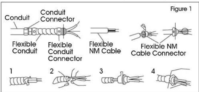
NOTE: Conduit may be required. (See Figure 1) Check local electrical codes. If wiring is run in conduit, ensure there is enough flexible conduit to allow heater to be turned, if necessary.
text_image
Conduit Conduit Connector Flexible Conduit Flexible Conduit Connector Flexible NM Cable Flexible NM Cable Connector Figure 1 1 2 3 4SPECIFICATIONS
| HEATER RATING AND VOLTAGE | BTU PER HR. | PHASE | CONTACTOR BUILT-IN | MOUNTING HEIGHT | MIN. DISTANCE FROM HORIZONTAL AIR THROW | MOUNTING HOLE TO WALL | ||||
| VERTICAL INSTALLATION | HORIZONTAL INSTALLATION | |||||||||
| MIN. MAX. MIN. | MAX. | |||||||||
| H-6517 | * 5000 W @ 240 V4165 W @ 240 V3332 W @ 240 V2500 W @ 240 V | 17,06514,21511,3658,533 | 1 | No | 6' | 11' | 6' | 8' | 18' | **13" |
| * 3750 W @ 208 V3123 W @ 208 V2500 W @ 208 V1874 W @ 208 V | 12,79910,6598,5336,396 | 1 | No | 6' | 11' | 6' | 8' | 18' | **13" | |
| H-6518 | * 7500 W @ 240 V6250 W @ 240 V5000 W @ 240 V3750 W @ 240 V | 25,59821,33117,06512,799 | 1 | Yes | 6' | 11' | 6' | 8' | 18' | **13" |
| * 5625 W @ 208 V4685 W @ 208 V3750 W @ 208 V2812 W @ 208 V | 19,19815,99012,7999,598 | 1 | Yes | 6' | 11' | 6' | 8' | 18' | **13" | |
*Heater is shipped from factory wired for these wattages. Heater can be field adjusted to the other wattages. (See Heat Output Adjustments, page 5)
**48" when heater air flow is between 45° downward and vertical.
WARNING
When using electric appliances, basic precautions should always be followed to reduce the risk of fire, electric shock and injury to persons, including the following:
- Read all instructions before installing or using this heater.
- This heater is hot when in use. To avoid burns, do not let bare skin touch hot surfaces. Keep combustible materials, such as furniture, pillows, bedding, papers, clothes, curtains, etc., at least 3' from the front of the heater.
- Extreme caution is necessary when any heater is used by or near children and whenever the heater is left operating and unattended.
- Do not operate any heater after it malfunctions. Disconnect power at service panel and have heater inspected by a qualified electrician before using.
- Do not use outdoors.
- To disconnect heater, turn controls to "off" and turn off power to heater circuit at main disconnect panel.
- Do not insert or allow foreign objects to enter any ventilation or exhaust opening, as this may cause an electric shock, fire or damage to the heater.
-
To prevent a possible fire, do not block air intake or exhaust in any manner.
-
A heater has hot and arcing or sparking parts inside. Do not use it in areas where gasoline, paint or flammable liquids are used or stored.
- Use this heater only as described in these instructions. Any other use not recommended by the manufacturer may cause fire, electric shock or injury to persons.
- This heater is provided with a red alarm light that will illuminate only if the heater has turned off as a result of overheating. If the light is on, immediately turn the heater off and inspect for any objects on or adjacent to the heater that may have blocked the airflow or otherwise caused high temperatures to have occurred. DO NOT OPERATE THE HEATER WITH THE ALARM LIGHT ILLUMINATED.
- This heater is intended for comfort heating applications and not intended for use in special environments. Do not use in damp or wet locations, such as marine or greenhouse or in areas where corrosive or chemical agents are present.
- When installing, see Installation on page 4 for additional warnings and precautions.
- For safe and efficient operation, and to extend the life of the heater, keep heater clean. See Cleaning the Heater, page 7.
SAFETY

WARNING! To prevent a possible fire, injury to persons or damage to the heater, adhere to the following safety precautions:
- Disconnect all power coming to heater at main service panel before wiring or servicing.
- All wiring procedures and connections must be in accordance with the national and local codes having jurisdiction and the heater must be grounded.
- Verify the power supply voltage coming to heater matches the ratings as shown on the heater nameplate.

CAUTION! Energizing heater at a voltage greater than the voltage printed on the nameplate will damage the heater, void the warranty and could cause a fire.

CAUTION! High temperature. Risk of fire. Keep electrical cords, drapery, furnishings and other combustibles at least 3' from front of heater. Do not install heater behind doors, below towel racks or in an area where it is subject to being blocked by furniture, curtains or storage materials. Hot air from the heater may damage certain fabrics and plastics.
- To reduce the risk of fire, do not store or use gasoline or other flammable vapors and liquids in the vicinity of the heater.
- When heater is to be wall- or ceiling-mounted, the anchoring hardware must be strong enough to support the total weight of the heater, plus the weight of the mounting hardware. Failure to properly mount the heater to the building structure could allow the heater to fall.
- The following minimum clearances must be maintained:
- For vertical airflow, bottom of heater to floor: 6' minimum, 11' maximum
- For horizontal airflow, bottom of heater to floor: 6' minimum, 8' maximum
- Sides of heater to adjacent wall: airflow from horizontal to 45° downward: 13"; airflow from 45° downward to straight down: 48"
- Discharge to any object: 36" minimum
- Do not use heater to dry paint or plaster. Sawdust and drywall sanding dust will permanently damage the heater and must be kept out of the heater.
INSTALLATION
PREPARATION
- Remove the heater from the box and inspect it for any damage. If it appears to be damaged, call Uline Customer Service at 1-800-295-5510.
- The heater should be installed out of traffic areas and at least 6' off the floor. (See Figure 2)

text_image
Front View 12½" 14" 13" 6½" 12¾" Mounting Location 1¾" 1/2", 3/4" (2) Side View Figure 2 Minimum Distance to Wall 13" Figure 2- The direction of air flow should not be restricted (i.e., by columns or machinery). The air should flow perpendicular to exposed walls, rather than blowing directly at them.
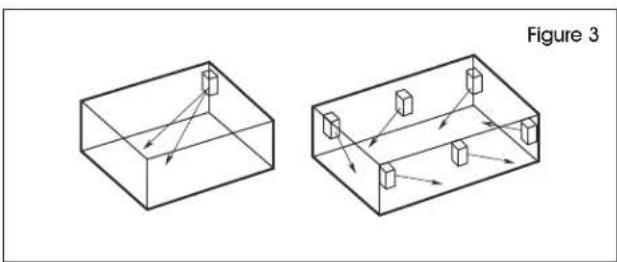
- When more than one heater is used in an area, the heaters should be arranged so the air discharge of each heater supports the air flow of the others to provide best circulation of warm air. (See Figure 3)
natural_image
Two isometric diagrams showing 3D rectangular blocks with internal arrows, labeled Figure 3 (no text or symbols on the blocks themselves)MOUNTING
- Remove the mounting bracket from the heating unit by loosening the bracket screws with a wrench and slipping the handle off over the screw heads.
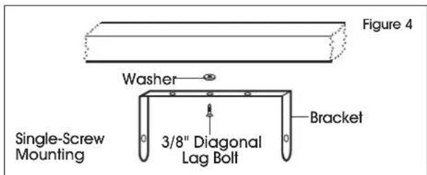
- Locate a stud in the ceiling and attach the mounting bracket to the ceiling joist. (See Figure 4)
text_image
Figure 4 Washer Single-Screw Mounting 3/8" Diagonal Lag Bolt Bracket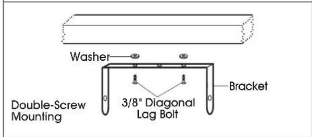
text_image
Washer Double-Screw Mounting 3/8" Diagonal Lag Bolt Bracket- Place a washer on the screw between the bracket and the ceiling to act as a spacer and screw them into the stud. Tighten the screws enough to securely hold the heating unit with the air flow pointed in the proper direction.
- Lift the heater up and into the mounting bracket. Align the screws on each side of the heater with the keyhole slots in the mounting brackets. If the heater is to be tilted, it must be positioned in the lower keyhole slots. (See Figure 5)
- Tighten the bracket screws so the unit is securely suspended at the desired position.
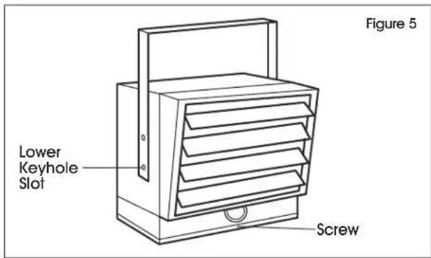
text_image
Figure 5 Lower Keyhole Slot ScrewINSTALLATION CONTINUED
WIRING
- To connect the power to the heater, remove the screw from the front of the unit. This allows the hinged bottom to open, providing access to the electrical wiring and connectors. (See Figure 5)
- Attach the cable connectors to the unit and slide the 10 gauge or thicker wire through the cable connector. (See Figure 1)
- Pull enough wire through the connector to work with when making the connections.

NOTE: Wiring compartment volume: 370 in ^4 .
- Connect the wire to the power terminal block located in the base of the heater. (See Figure 6)
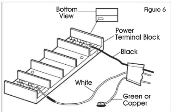
text_image
Bottom View Figure 6 Power Terminal Block Black White Green or Copper
NOTE: Unit is 240/208 volts. When wiring a two conductor cable with ground, the white wire must be marked black by adding a piece of black electrical tape to the wire near the point of connection.

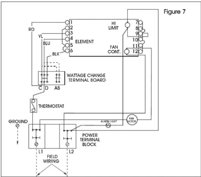
NOTE: To decrease the heat output of the heating unit, see Adjusting Heat Output below and Figure 7.

WARNING! To prevent possible electric shock, disconnect power to the heater at the main service box before attempting to adjust the heat output of this unit.
ADJUSTING HEAT OUTPUT
Heat output can be increased or decreased by switching wires at the wattage change terminal board. The H-6517 is factory wired to deliver a heat output of 17,065 BTU per hour. The H-6518 is factory wired to deliver a heat output of 25,598 BTU per hour. For less heat output, refer to the Heat Output Adjustments table and change the wires at the wattage change terminal board. (See Figure 7)
HEAT OUTPUT ADJUSTMENTS FOR H-6517
| BTU/HR VOLTS WATTS | MAX FUSE SIZE | HEATER AMPS | MOVE JUMPERS FROM C-D TO A-B | ||
| 17,065 | 240 | 5000 | 30 | 20.9 | None |
| 14,215 | 240 | 4165 | 25 | 17.4 | Blue |
| 11,365 | 240 | 3332 | 20 | 13.9 | Blue and Yellow |
| 8,533 | 240 | 2500 | 15 | 10.4 | Blue, Yellow and Red |
| 12,799 | 208 | 3750 | 25 | 18.0 | None |
| 10,659 | 208 | 3123 | 20 | 15.0 | Blue |
| 8,533 | 208 | 2500 | 15 | 12.0 | Blue and Yellow |
| 6,396 | 208 | 1874 | 15 | 9.0 | Blue, Yellow and Red |
HEAT OUTPUT ADJUSTMENTS FOR H-6518
| BTU/HR VOLTS WATTS | MAX FUSE SIZE | HEATER AMPS | MOVE JUMPERS FROM C-D TO A-B | ||
| 25,598 | 240 | 7,500 | 45 | 31.3 | None |
| 21,331 | 240 | 6,250 | 35 | 26.1 | Blue |
| 17,065 | 240 | 5,000 | 30 | 20.9 | Blue and Yellow |
| 12,799 | 240 | 3,750 | 20 | 15.7 | Blue, Yellow and Red |
| 19,198 | 208 | 5,625 | 40 | 27.1 | None |
| 15,990 | 208 | 4,685 | 30 | 22.3 | Blue |
| 12,799 | 208 | 3,750 | 25 | 18.1 | Blue and Yellow |
| 9,598 | 208 | 2,812 | 20 | 13.6 | Blue, Yellow and Red |
flowchart
graph TD
    A["Ground"] --> B["L1"]
    B --> C["FIELD WIRING"]
    C --> D["POWER TERMINAL BLOCK"]
    D --> E["THERMOSTAT"]
    E --> F["WATTAGE CHANGE TERMINAL BOARD"]
    F --> G["ELEMENT"]
    G --> H["HI LIMIT"]
    H --> I["FAN CONT."]
    I --> J["FAN MOTOR"]
    J --> K["ALARM LIGHT"]
    K --> L["Ground"]
    style A fill:#f9f,stroke:#333
    style B fill:#ccf,stroke:#333
    style C fill:#cfc,stroke:#333
    style D fill:#fcc,stroke:#333
    style E fill:#cff,stroke:#333
    style F fill:#ffc,stroke:#333
    style G fill:#cfc,stroke:#333
    style H fill:#fcc,stroke:#333
    style I fill:#ffc,stroke:#333
    style J fill:#cfc,stroke:#333
    style K fill:#fcc,stroke:#333
    style L fill:#cfc,stroke:#333
OPERATION
- Heater must be properly installed before operation.
- After heater is completely assembled, rotate thermostat knob counterclockwise until control stops. This is the minimum heat setting.
- Turn power supply to heater "ON" at main switch panel.
- Heater should not operate. If it operates, disconnect power and recheck wiring.
- Rotate thermostat clockwise until it stops (maximum heat setting).
- Heater should turn on after a brief delay (see Automatic Fan Delay, below). If heater and fan do not come on, disconnect power and check wiring.

NOTE: The first time you operate the unit, it may smoke slightly. This is due to the residual cleaning agents used to clean the element when the heater is manufactured. This is normal and does not indicate a problem with the unit. Smoking will stop once heater operates for a few minutes.
- Allow heater to continue to operate until room reaches desired temperature. Then, slowly rotate thermostat knob counterclockwise until thermostat turns off. Heater will cycle on and off to maintain room temperature.

NOTE: The fan delay will keep the fan running until the elements cool.
- It may be necessary to adjust thermostat until exact comfort level is attained. Rotation in the clockwise direction will increase the amount of time the heater will produce heat. Rotation in the counterclockwise direction will reduce the amount of time the heater is on.
Automatic Fan Delay: When the thermostat calls for heat, fan action is delayed momentarily until the heating elements warm. This prevents the circulation of cold air. When the heater raises the temperature of the room to the set temperature, the heating element is turned off but the fan will continue to run until the heating element cools down. This prevents exposing the unit to residual heat, providing a higher comfort level and prolonged element life.
Automatic Thermal Limit: The heater will automatically shut off in the event of overheating. The heater will turn on when the operating temperature returns to normal. Should the unit overheat and activate the thermal limit, the cause of the overheating should be determined before further operation.

WARNING! Do not tamper with or bypass any safety limits inside heater.

CAUTION! Do not continue to attempt to use the heater if the thermal limit repeatedly operates. Doing so could permanently damage the heater or create a fire or safety hazard.

NOTE: If the unit is installed in an area where the temperature is below 50^ F, the fan may cycle on and off until the temperature in the room rises above 50^ F. This is normal and does not indicate a problem with the unit. As soon as the heater warms the air in the room above 50^ F, the fan will operate continually until the thermostat has reached the desired temperature.
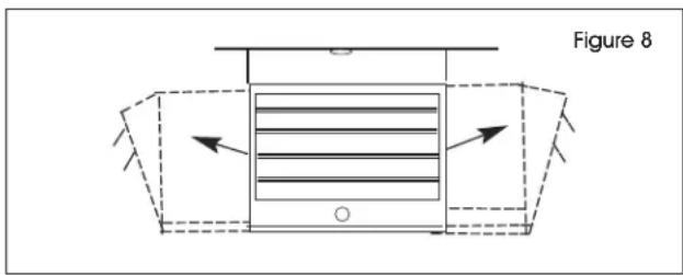
ADJUSTING AIR FLOW DIRECTION
- Turning the unit: If the unit has been installed with a single lag bolt, simply turn the entire unit as needed to adjust air flow. (See Figure 8)
text_image
Figure 8- Tilting the unit: Loosen the bracket screws in the lower keyhole slot, tilt the heater to the desired position and re-tighten the bracket screws.

NOTE: To tilt the heater, it must be mounted in bottom key hole slots of mounting bracket to maintain adequate clearance and prevent possible overheating.
- Adjust the louvers to the desired position.

NOTE: The louvers are designed so they cannot be completely closed. Do not attempt to prevent this feature. Damage to the unit can result.

WARNING! All servicing beyond simple cleaning that requires disassembly should be performed by qualified service personnel.

WARNING! To reduce risk of fire and electric shock or injury, disconnect all power at main service panel and check that the element is cool before servicing or performing maintenance.
OPERATION CONTINUED
CLEANING THE HEATER
It is important to keep the heater clean. The heater will give years of service and comfort with only minimum care. To assure efficient operation, follow the simple instructions below:

WARNING! All servicing beyond simple cleaning that requires disassembly should be performed by qualified service personnel.

WARNING! To reduce risk of fire and electric shock or injury, disconnect all power coming to heater at main service panel and check that the element is cool before servicing or performing maintenance.
- After the heater has cooled, a vacuum cleaner with brush attachment may be used to remove dust and lint from exterior surfaces of the heater including the grille openings.
- With a damp cloth, wipe dust and lint from grille and exterior surfaces.
- Return power to heater and check to ensure it is operating properly.
MAINTENANCE CLEANING
At least annually, the heater should be cleaned and serviced by a qualified service person to assure safe and efficient operation.
After completing the cleaning and servicing, the heater should be checked for proper operation.
ULINE H-6517, H-6518 CALENTADORES ELÉCTRICOS
800-295-5510 uline.mx
natural_image
Line drawing of a multi-tiered industrial machine or storage unit (no text or symbols)
Llave Ajustable
TORNILLERÍA NECESARIA
natural_image
Line drawing of a multi-tiered industrial machine or storage unit (no text or symbols)
Clé ajustable
MATÉRIEL REQUIS
natural_image
Two isometric diagrams showing 3D rectangular blocks with internal arrows, labeled Figure 3 (no text or symbols on the blocks themselves)MONTAGE
natural_image
Diagram of a device with horizontal lines inside a container, enclosed in a dashed rectangular frame (no text or symbols)Figure 8


