
H-6513 - Heating Uline - Free user manual and instructions
Find the device manual for free H-6513 Uline in PDF.

User questions about H-6513 Uline
0 question about this device. Answer the ones you know or ask your own.
Ask a new question about this device
Download the instructions for your Heating in PDF format for free! Find your manual H-6513 - Uline and take your electronic device back in hand. On this page are published all the documents necessary for the use of your device. H-6513 by Uline.
USER MANUAL H-6513 Uline
ULINE H-6513, H-6514 MULTI-FUEL HEATER
1-800-295-5510 uline.com
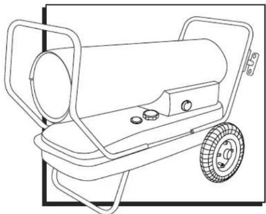
natural_image
Line drawing of a portable water heater with wheels and control panel (no text or symbols)SAFETY

DANGER! Read and understand all of these instructions before assembling, starting or servicing the heater. Comply with the instructions and warnings provided with this heater. Failure to comply can result in fire or explosion that can cause property loss, bodily injury or loss of life. Only persons who can follow and understand these instructions should operate or service this heater. For additional information, contact Uline Customer Service at 1-800-295-5510.

DANGER! Not for use in residential living areas or in enclosed spaces without adequate ventilation. For outdoor use. Indoor use permitted only for the temporary heating of adequately ventilated buildings or structures under construction, alteration or repair. This is an unvented portable heater that uses air (oxygen) from within the area in which it is used. Failure to provide adequate combustion and ventilation air will result in asphyxiation, carbon monoxide poisoning, bodily injury or death. See Ventilation on page 5.

WARNING! Fire, burn, inhalation and explosion hazard. Keep combustibles such as building materials, paper or cardboard a safe distance away from the heater. Never use the heater in spaces which contain products such as gasoline, solvents, paint thinners, dust particles, volatile or airborne combustibles or any unknown chemicals. Bulk fuel storage should be a minimum of 25' from heater.
WARNING! Do not start the heater when excess oil has accumulated.
WARNING! Do not start the heater when the chamber is hot.
WARNING! California residents: This product contains chemicals, including lead, known to the state of California to cause birth defects or other reproductive harm. Wash hands after handling.
Massachusetts residents: Massachusetts state law prohibits the use of this heater in any building that is used in whole or in part for human habitation. Use of this heating device in Massachusetts requires local fire department permit (M.G.L.C. 148, Section 10A).
New York City residents: The New York City Fire Code prohibits the storage, handling and use of kerosene fueled heaters for space heating. Any person violating that provision may be punished by a fine up to \$10,000 and a term of imprisonment of up to 6 months.
The installation of this heater shall comply with the regulations of the authorities having jurisdiction.
SAFETY CONTINUED
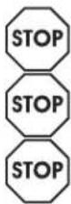
STOP
WARNING! Risk of indoor air pollution!
The products described in these instructions are kerosene direct-fired, forced air heaters. Kerosene forced air heaters are primarily intended for use for temporary heating of buildings under construction, alteration or repair. Direct-fired means that all of the combustion products of the heater enter the heated space. This appliance is rated at 98% combustion efficiency, but does produce small amounts of carbon monoxide.

DANGER! Carbon monoxide poison may lead to death.
- Carbon monoxide is toxic. Humans can tolerate only small amounts of carbon monoxide, so precautions should be taken to provide proper ventilation. Failure to provide proper ventilation in accordance with these instructions can result in death.
• People with breathing problems should consult a physician before using this heater. - Early signs of carbon monoxide poisoning resemble the flu. Symptoms of improper ventilation/carbon monoxide poisoning are headache, dizziness, nausea, dry mouth, sore throat and burning of nose and eyes.
- If you experience any of these symptoms, get fresh air at once. Have your heater serviced and check for proper ventilation. Some people are affected by carbon monoxide more than others. These include pregnant women, those with heart or lung problems, anemia or those under the influence of alcohol or at high altitudes.
- For outdoor use. Indoor use permitted only for the temporary heating of adequately ventilated buildings or structures under construction, alteration or repair. Provide at least a three square feet opening of outside air for every 100,000 BTU/HR heater rating. Refer to Ventilation on page 5 for more information.
STOP
WARNING! Risk of electrical shock.
- Use only the electrical power (voltage and frequency) specified on the model plate of the heater.
- Use only a properly grounded three prong outlet and extension cord.
- Always use 14 AWG or better extension cord. Always unplug the heater when not in use.
- Always install the heater so that it is not directly exposed to water spray, rain, dripping water or wind.
STOP
WARNING! Risk of burns, fire and explosion.
- Never use fuels such as gasoline, benzine, paint thinners or other oil compounds in this heater.
- Never refill the heater's fuel tank while the heater is operating or still hot. This heater is extremely hot while in operation.
- Never block air inlet (rear) or air outlet (front). Never use duct work in front or rear of heater. Never move or handle heater while still hot.
- Never transport heater with fuel in tank. Never use with an external fuel tank.

CAUTION! Hot while in operation. Do not touch. Keep children, animals, clothing and combustibles away from heater.
- Keep all combustible materials away from this heater.
| MINIMUM CLEARANCE FROM COMBUSTIBLES | ||
| SIDES TOP FRONT | ||
| 4' 4' 8' | ||
• Always locate heater on a stable and level surface.
- If your heater is equipped with a thermostat, once it is plugged in, it can start at anytime in accordance with the thermostat setting.
SPECIFICATIONS
| MODEL NO. H-6513 H-6514 | ||
| BTU/HR | 135,000 190,000 | |
| FUEL CONSUMPTION (GAL/HR) | 1.00 1.42 | |
| FUEL TANK CAPACITY (GAL) | 10.0 13.0 | |
| PUMP PRESSURE (PSI) | 5.5 8.5 | |
| VOLTS (AC/Hz) | 120 VAC/60 Hz 120 VAC/60 Hz | |
| AMPS | 2.3 A 2.7 A | |
| PHASE | Single Single | |
FEATURES
text_image
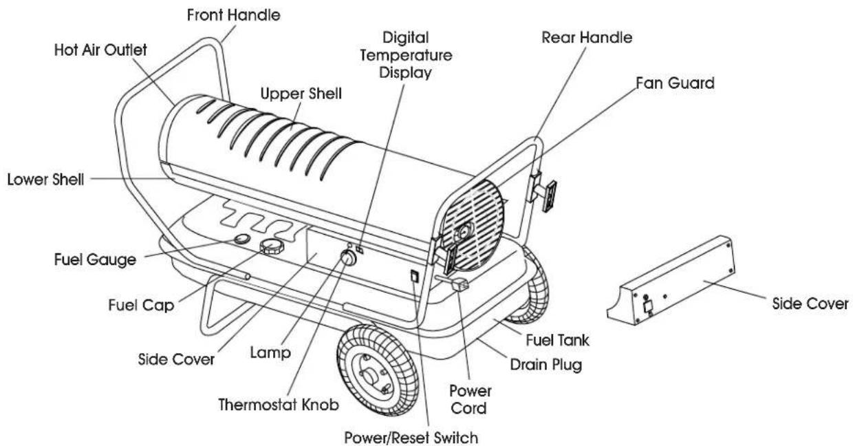
Front Handle Hot Air Outlet Upper Shell Digital Temperature Display Rear Handle Fan Guard Lower Shell Fuel Gauge Fuel Cap Side Cover Lamp Thermostat Knob Power/Reset Switch Fuel Tank Drain Plug Power Cord Side CoverPARTS
text_image
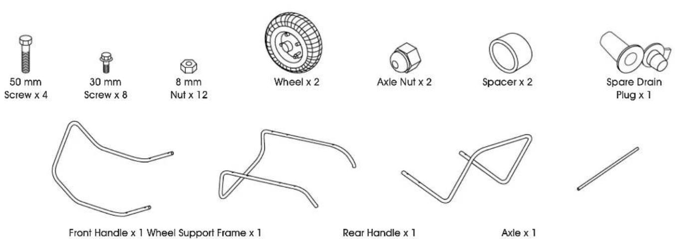
50 mm Screw x 4 30 mm Screw x 8 8 mm Nut x 12 Wheel x 2 Axle Nut x 2 Spacer x 2 Spare Drain Plug x 1 Front Handle x 1 Wheel Support Frame x 1 Rear Handle x 1 Axle x 1ASSEMBLY
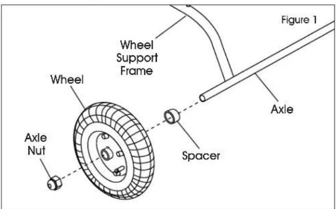
- Insert axle through holes in wheel support frame.
- Slide spacer onto axle.
- Slide wheel onto axle and hold in place with axle nuts. (See Figure 1)
text_image
Wheel Wheel Support Frame Figure 1 Axle Spacer Axle Nut
NOTE: Do not tighten nuts fully. You will need to remove the wheels in a later step.
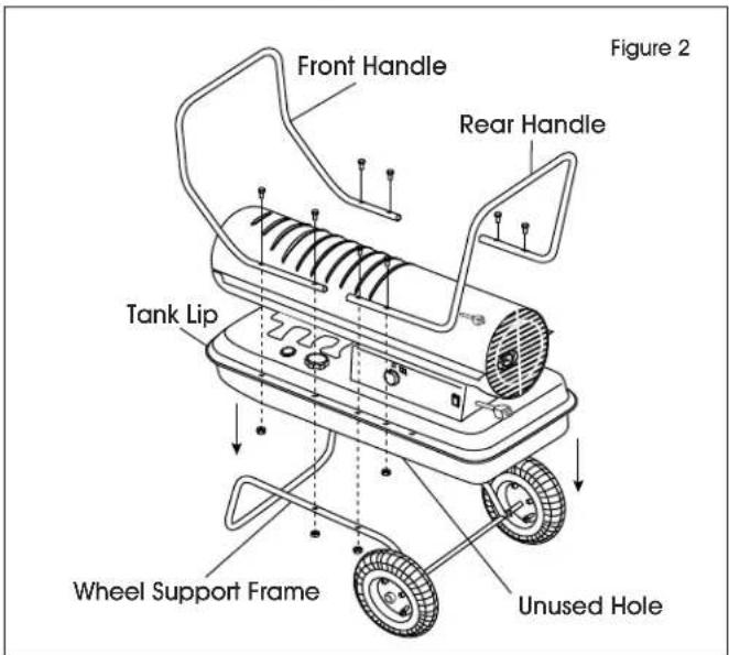
- Place heater on wheel support frame and line up holes on the fuel tank lip.
- Attach front handle with two 50 mm screws and two nuts through the second hole from the front on both sides of the tank lip and wheel support frame and tighten firmly.
-
Insert two 30 mm screws through the first hole from the front in the tank lip and tighten firmly. Ensure all four screws are secure.
-
Attach rear handle with two 50 mm screws and two nuts through the third hole from the rear of the heater on either side. (See Figure 2)
text_image
Front Handle Rear Handle Tank Lip Wheel Support Frame Unused Hole Figure 2
NOTE: You will secure the rear handle in step 10.
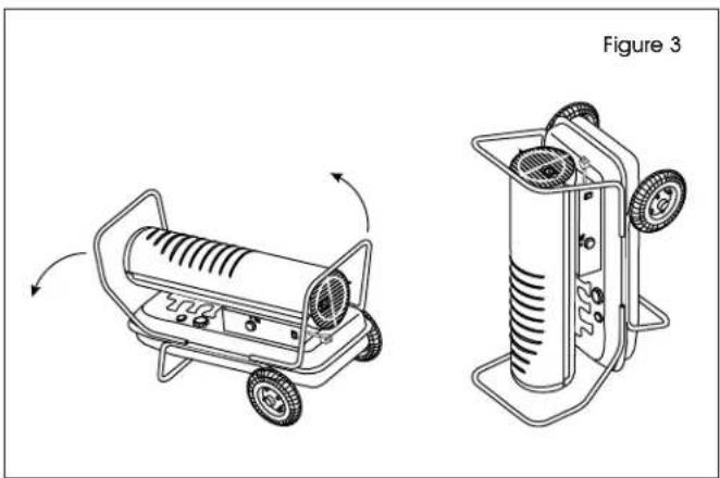
- Check that the tank does not contain fuel. If the tank is empty, gently tilt the heater so it is resting on the front handle. (See Figure 3)

NOTE: Do not tilt heater if tank contains fuel.
natural_image
Technical line drawing of a portable heater and its side-mounted device (no text or symbols)- Remove the wheels to secure the second set of screws through the rear handle.
- Secure the rear handle with two 30 mm screws and two nuts and tighten firmly.
- Replace wheels and tighten with the wheel nuts.
- Tilt heater back down onto wheels and check all screws and nuts to ensure they are secure.
OPERATION
FUELING THE HEATER
KEROSENE (1-K)
For optimal performance of this heater, it is strongly suggested that 1-K kerosene be used. 1-K kerosene has been refined to virtually eliminate contaminants, such as sulfur, which can cause a rotten egg odor during the operation of the heater. Using diesel fuel can cause excess soot production. Do not use bio-diesel, as this fuel will damage heater's seals and filter.
• CSA certified for use with 1-K kerosene, no. 1 and no. 2 diesel, JP8/Jet A Fuel, no. 1 and no. 2 fuel oil.
Do not use any fuel that is not approved above.

DANGER! Never refuel this heater while it is hot or operating. Fire or explosion could result.

CAUTION! Never fill the fuel tank indoors. Always fill the tank outdoors. Ensure the heater is on level ground.

WARNING! Do not use gasoline or crankcase drainings.
- Never use fuel such as benzene, alcohol, white gas, camp stove fuel, paint thinners or other oil compounds in this heater. These are volatile fuels that can cause a fire or explosion.
- Never store kerosene in living space.
- Kerosene should be stored in a well-ventilated area outside the living area.
- Never store kerosene in direct sunlight or near a source of heat.
- Never use kerosene that has been stored from one season to the next. Kerosene deteriorates over time. Old kerosene will not burn properly in this heater.

NOTE: Kerosene should only be stored in a blue container that is clearly marked "Kerosene". Never store kerosene in a red container. Red is associated with gasoline.
VENTILATION
- Risk of indoor air pollution and carbon monoxide poisoning. Use heater only in well ventilated areas.
• Refer to Safety section on pages 1 and 2 for information about carbon monoxide poisoning.

DANGER! Carbon monoxide poisoning may lead to death.
- Always provide a fresh air opening in the heated space of at least three square feet for each 100,00 BTU/HR of heater output. Provide a larger opening if more heaters are being used.
| MINIMUM VENTILATION OPENING NEEDED | |
| H-6513 H-6514 | |
| 4.1 ft. ^2 | 5.7 ft. ^2 |
IGNITING THE HEATER
- Fill the tank with kerosene or other approved fuel until needle on fuel gauge points to "F."
- Replace fuel cap and tighten firmly.
- Connect the heater to a three prong power source. A three-prong, properly grounded extension cord that is at least 6 feet long and is a minimum of 14 AWG rating must be used.
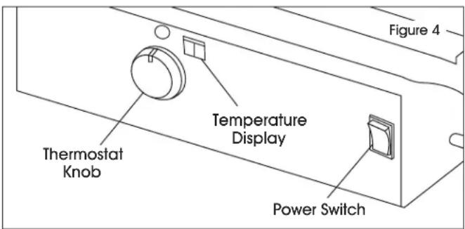
- Turn thermostat control knob to desired temperature setting. The thermostat set range is from 40^ F to 110^ F.
- Move power switch to "on" position. The power indicator light and room temperature display will illuminate and heater will ignite. (See Figure 4)

NOTE: If the heater does not ignite, the thermostat may be set too low. Turn the control knob to a higher setting until the heater ignites. If the heater does not ignite, turn off and check steps 1-3 above. Then, turn on.
text_image
Figure 4 Temperature Display Thermostat Knob Power Switch
NOTE: If the heater still does not ignite, refer to Troubleshooting on page 9.
The room temperature display will indicate the following:
- When the temperature is less than 0^ F, the display says LO.
- When the temperature is more than 99°F, the display says HI.
- Between 0°F and 99°F the display shows actual temperature.
STOPPING/RESTARTING HEATER
To stop the heater, move the power switch to the "off" position and unplug the power cord.
To restart the heater, wait 10 seconds and follow ignition steps.
MAINTENANCE
LONG-TERM STORAGE
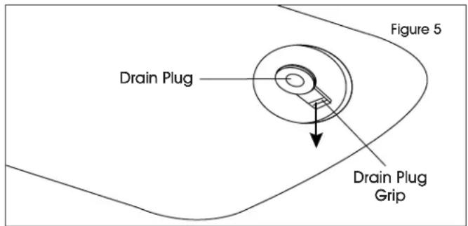
- Drain fuel through the drain plug in the bottom of the fuel tank.
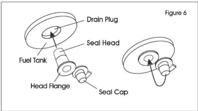
- To remove the drain plug, pull the plug grip downward and remove the seal head from the drain hole in the tank. (See Figures 5 and 6)
text_image
Drain Plug Drain Plug Grip Figure 5- Using a small amount of kerosene, rinse and swirl the kerosene inside of the fuel tank and empty the tank fully.
- To replace the drain plug, push the drain head fully into the drain hole and secure by pushing the seal cap fully into the head hole. (See Figure 6)
text_image
Drain Plug Seal Head Fuel Tank Head Flange Seal Cap Figure 6
IMPORTANT! Never store leftover kerosene between seasons, as using old fuel can damage heater.
SERVICE

WARNING! Never service heater while it is plugged in or hot.
Do not tamper with the unit. Have a competent serviceman make any necessary adjustment or repairs.
Use only original equipment manufacturer parts. The use of alternate or third party components can cause unsafe operating conditions and will void your warranty.

NOTE: To order parts, call Uline Customer Service at 1-800-295-5510.
Follow a maintenance schedule as follows:
FUEL/FUEL TANK
Flush tank every 200 hours of operation as needed.

NOTE: Follow the long term storage instructions to flush the tank.
Do not flush with water; use fresh 1-K kerosene only.
AIR FILTERS
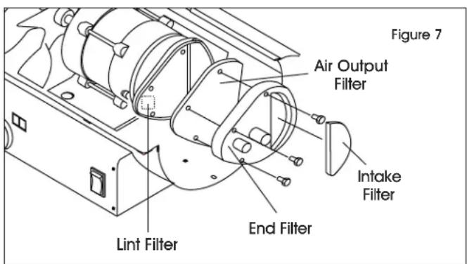
The air intake filter should be replaced or washed with soap and water and dried thoroughly every 500 hours of operation, or less depending on conditions. (See Figure 7)
The output and lint filters should be replaced every 500 hours of operation, or less depending on conditions. (See Figure 7)

NOTE: Use of diesel fuel may require additional maintenance.
text_image
Figure 7 Air Output Filter Intake Filter End Filter Lint FilterFAN BLADES
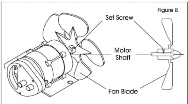
Blades should be cleaned at least once per heating season, depending on conditions. Remove all accumulated dust and dirt with a damp cloth, taking care not to bend any of the fan blades. Ensure the blades are dry before restarting the heater. (See Figure 8)
text_image
Set Screw Motor Shaft Fan Blade Figure 8MAINTENANCE CONTINUED
FUEL FILTER
The fuel filter should be cleaned at least twice per heating season. Clean the filter by rinsing it in clean 1-K Kerosene. Contaminated fuel could make cleaning the fuel filter necessary immediately.

NOTE: To remove, turn filter 90° counterclockwise. (See Figure 9)
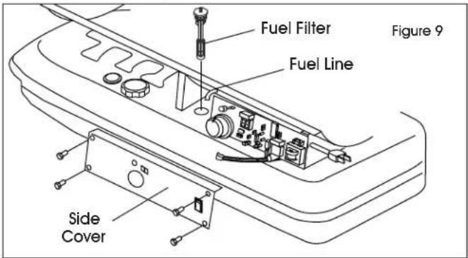
text_image
Fuel Filter Fuel Line Figure 9 Side CoverSPARK PLUG
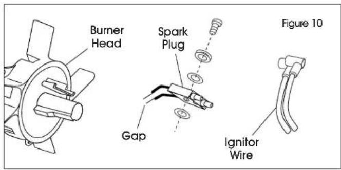
Clean and re-gap every 600 hours of operation, or replace as needed. After removing the spark plug, clean the terminals with a wire brush. Re-gap the terminals to 0.140". (See Figure 10)
text_image
Burner Head Spark Plug Gap Ignitor Wire Figure 10PHOTOCELL
The photocell should be cleaned using a cotton swab dipped in alcohol or water at least once per heating season, or more depending on conditions. (See Figure 11)
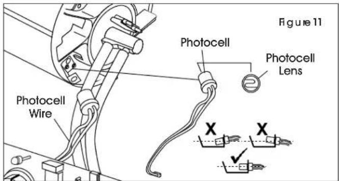
text_image
Figure 11 Photocell Photocell Lens Photocell Wire X XPUMP PRESSURE
- While heater is operating, turn adjusting screw clockwise to increase or counterclockwise to decrease pressure. (See Figure 12)
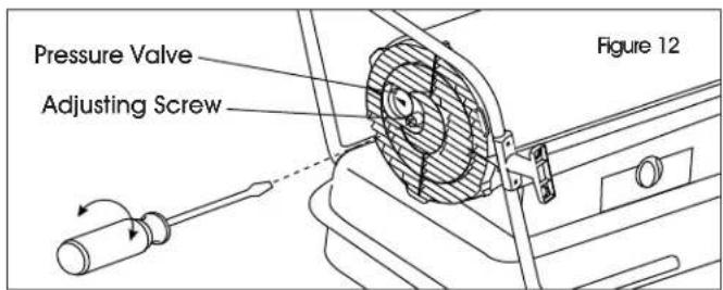
text_image
Pressure Valve Adjusting Screw Figure 12- Correct pump pressure is as follows:
| MODEL NUMBER PUMP PRESSURE | |
| H-6513 5.5 psi | |
| H-6514 8.5 psi | |
NOZZLES
Nozzles should be cleaned or replaced at least once per heating season. Contaminated fuel could make this necessary immediately.
- To clean dirt from nozzle, blow compressed air through nozzle front. (See Figure 13)

NOTE: It may be necessary to soak the nozzle in 1-K kerosene to loosen any dirt particles.
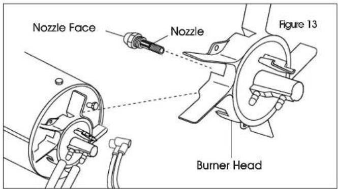
text_image
Nozzle Face Nozzle Figure 13 Burner HeadWIRING DIAGRAM
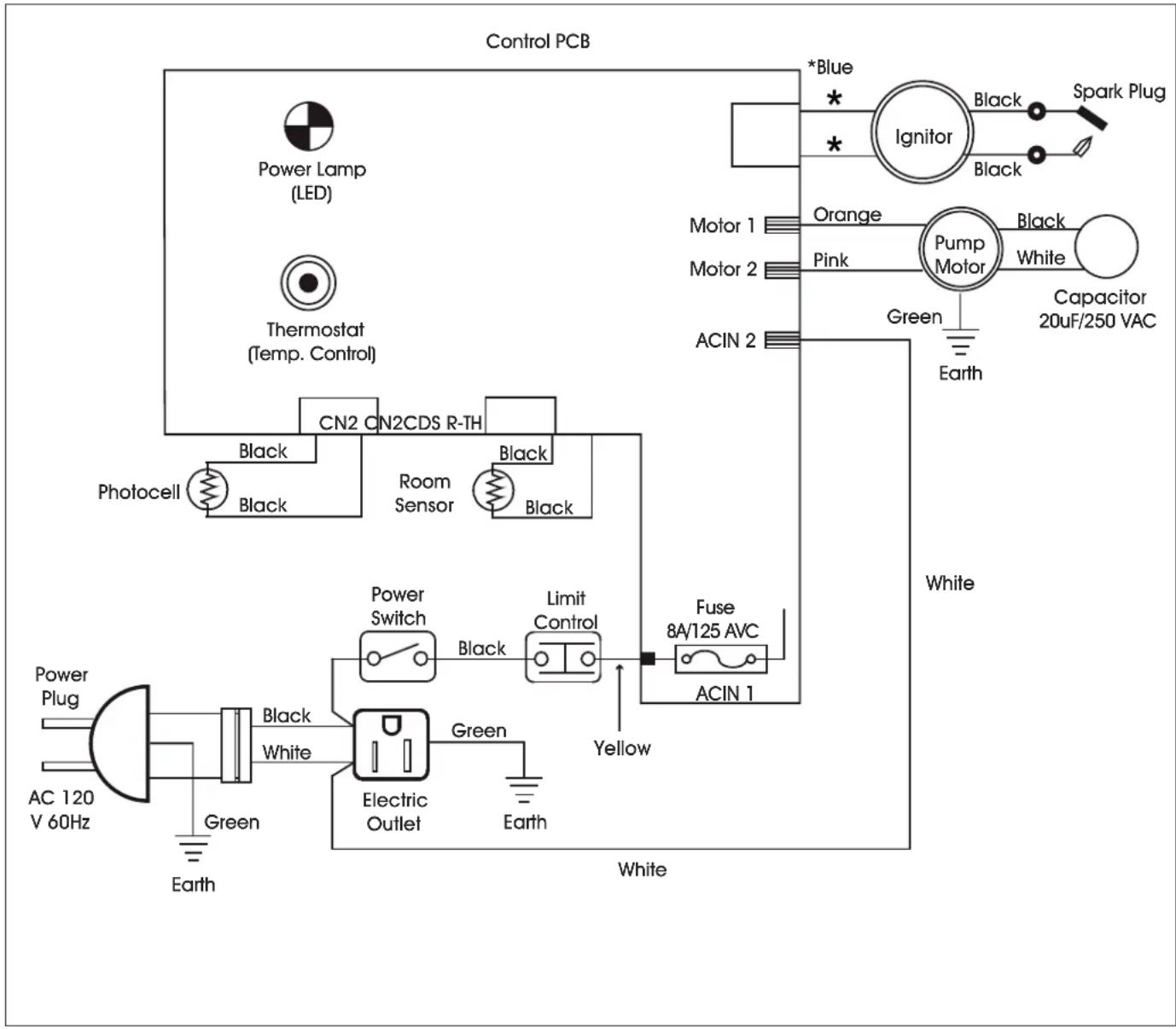
flowchart
graph TD
    A["Control PCB"] --> B["Power Lamp (LED)"]
    A --> C["Thermostat (Temp. Control)"]
    A --> D["Photocell"]
    D --> E["Black"]
    D --> F["Black"]
    D --> G["Room Sensor"]
    D --> H["Black"]
    D --> I["CN2 CN2CDS R-TH"]
    I --> J["Power Switch"]
    J --> K["Black"]
    J --> L["Limit Control"]
    L --> M["Fuse 8A/125 AVC"]
    M --> N["ACIN 1"]
    N --> O["White"]
    I --> P["Green"]
    P --> Q["Electric Outlet"]
    Q --> R["White"]
    I --> S["Black"]
    S --> T["Power Plug"]
    T --> U["AC 120 V 60Hz"]
    U --> V["Green"]
    V --> W["Earth"]
    I --> X["Black"]
    X --> Y["White"]
    I --> Z["Blue"]
    Z --> AA["Ignitor"]
    AA --> AB["Spark Plug"]
    AA --> AC["Orange"]
    AA --> AD["Pump Motor"]
    AD --> AE["Black"]
    AD --> AF["White"]
    AD --> AG["Capacitor 20uF/250 VAC"]
    AD --> AH["Green"]
    AH --> AI["Earth"]
    I --> AJ["Yellow"]
TROUBLESHOOTING
LOCATING SERIAL NUMBER
The serial number can be found on a white label on the right side cover of heater. It will begin with two digits, the letter "H" followed by six digits. For example: 13H123456. Have serial number ready before calling Uline Customer Service at 1-800-295-5510.
| OPERATING ISSUE CAUSE RECOMMENDATIONS | ||
| Heater ignites, but main PCB shuts off after a short period of time. Lamp flickers and LED display shows "E1." | Incorrect pump pressure.Dirty input, output or lint filter.Dirty fuel filter.Nozzle is dirty.Photocell lens is dirty.Photocell not installed properly.Photocell is defective.Improper electrical connection between main PCB and photocell. | Adjust pump pressure.Clean or replace air or lint filter.Clean or replace fuel filter.Clean or replace nozzle.Clean or replace photocell.Adjust photocell position.Replace photocell.Check wiring connections. (See wiring diagram on page 8) |
| Heater will not operate or motor runs for a short time. Lamp flickers and LED display shows "E1." | No kerosene in the fuel tank.Incorrect pump pressure.Corroded spark plug or incorrect plug gap.Dirty fuel filter.Dirty nozzle.Moisture in fuel tank.Improper electrical connection between transformer and circuit board.Ignitor wire not connected to spark plug.Defective ignitor. | Fill tank with fresh kerosene.Adjust pump pressure.Clean or replace spark plug. Adjust plug gap as necessary.Clean or replace fuel filter.Clean or replace nozzle.Rinse fuel tank with clean, fresh kerosene.Inspect all electrical connections. (See wiring diagram on page 8)Re-attach ignitor wire to spark plug.Replace ignitor. |
| Fan does not operate when heater is plugged in and power switch is in the on position. The lamp is flickering and/or LED display shows "E1" or "E2." | Thermostat is set too low.Broken electrical connection between main PCB and motor. | Rotate thermostat to a higher setting.Inspect all electrical connections. (See wiring diagram on page 8) |
| Lamp is flickering and LED display shows "E3." | Thermostat switch has failed. Replace thermostat switch. (See wiring diagram on page 8) | |
| Poor combustion and/or excess soot production. | Dirty input, output or lint filter.Dirty fuel filter.Poor quality of fuel.PSI is too high or too low. | Clean or replace air or lint filter.Clean or replace fuel filter.Flush fuel tank and refuel heater.Use proper pressure. |
| Heater does not turn on and the lamp is not lit. | Temperature limit sensor has overheated.No electrical power.Fuse is blown.Improper electrical connection between temperature limit sensor and circuit board. | Push power switch to off and allow heater to cool for 10 minutes. Restart heater.Check power cords for proper connection and test the power supply.Check and replace the fuse.Inspect all electrical connections. (See wiring diagram on page 8) |
ULINE H-6513, H-6514 CALENTADOR MULTICOMBUSTIBLE
800-295-5510 uline.mx
natural_image
Line drawing of a portable water heater with wheels and control panel (no text or symbols)SEGURIDAD

natural_image
Technical line drawing of a portable heater and its side-mounted device (Diagram 3), showing mechanical components and rotation arrows (no text or symbols)natural_image
Line drawing of a portable water heater with wheels and control panel (no text or symbols)SÉCURITÉ


