
H-11009 - Heating Uline - Free user manual and instructions
Find the device manual for free H-11009 Uline in PDF.

User questions about H-11009 Uline
0 question about this device. Answer the ones you know or ask your own.
Ask a new question about this device
Download the instructions for your Heating in PDF format for free! Find your manual H-11009 - Uline and take your electronic device back in hand. On this page are published all the documents necessary for the use of your device. H-11009 by Uline.
USER MANUAL H-11009 Uline
ULINE H-110 09 BATTERY-OPERATED FORCED AIR HEATER
TOOL NEEDED
Phillips
Screwdriver
1-800-295-5510 uline.com
natural_image
Technical line drawing of a cylindrical device with internal components and mounting holes (no text or symbols)PARTS

natural_image
Technical line drawing of a heater assembly with labeled components (no text or symbols beyond label)Heater x 1
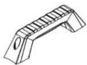
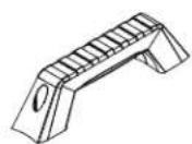
Carry Handle x 1
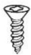
15 mm Screw x 2
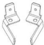
Dewalt ^® Terminals x 1 (Pre-installed)
Milwaukee ^® Terminals x
SAFETY

DANGER! General Hazard Warning – Read and understand all the instructions in this manual before assembling, starting or servicing the heater. Be sure to comply with the instructions and warnings provided with this heater. Failure to comply with the precautions and instructions provided with this heater can result in death, serious bodily injury, property loss or damage from the hazards of fire, soot production, explosions, burns, asphyxiation or carbon monoxide poisoning. Only people who can follow and understand these instructions should operate or service this heater.

DANGER! Not for use in residential living areas or in enclosed spaces without adequate ventilation. This heater is not for use where exposed to the weather. Indoor use permitted only for the temporary heating of adequately ventilated buildings or structures under construction, alteration or repair. This is an unvented portable heater that uses air (Oxygen) from within the area in which it is used. Failure to provide adequate combustion and ventilation air will result in asphyxiation, carbon monoxide poisoning, bodily injury or death. Refer to "Ventilation" on Page 4.

WARNING! Heater is intended for use without ducts. Do not connect to ducts. Do not tamper with the unit. Have a competent serviceman make any adjustment or repair. Do not operate the unit near combustible surfaces or materials. Allow the unit to cool before shutting down. Remove battery if the heater is not in use.

WARNING! Never leave heater unattended while burning or while connected to a power source.

WARNING! FIRE, BURN, INHALATION AND EXPLOSION HAZARD. Keep combustibles such as building materials, paper or cardboard a safe distance away from the heater as recommended by these instructions. Never use the heater in spaces that contain products such as gasoline, solvents, paint thinners, dust particles, volatile or airborne combustibles or any unknown chemicals. Bulk fuel storage should be a minimum of 25' from heater.
SAFETY CONTINUED

WARNING! Do not operate this heater until reading and thoroughly understanding these instructions. Only people who can read and understand these instructions should use or service this heater.

WARNING! Do not start the heater when excess oil has accumulated.

WARNING! Do not start the heater when the chamber is hot.

CALIFORNIA WARNING: Risk of cancer and reproductive harm from exposure to lead and lead compounds. See www.P65Warnings.ca.gov.
- Massachusetts residents: Massachusetts state law prohibits the use of this heater in any building that is used in whole or in part for human habitation. Use of this heating device in Massachusetts requires local fire department permit (M.G.L.C. 148, Section 10A).
- New York City residents: The New York City Fire Code prohibits the storage, handling and use of kerosene fueled heaters for space heating. Any person violating that provision may be punished by a fine up to \$10,000 and a term of imprisonment of up to six months.
• Installation of the equipment should be in accordance with the regulation of authorities having jurisdiction and CSA standard b139.

WARNING! Risk of indoor air pollution. The products described in these instructions are kerosene direct-fired, forced air heaters. Kerosene forced air heaters are primarily intended for use for temporary heating of buildings under construction, alteration or repair. Direct-fired means that all the combustion products of the heater enter the heated space. This appliance is rated at 98% combustion efficiency but does produce small amounts of carbon monoxide.

DANGER! Carbon monoxide poisoning may lead to death.

DANGER! Carbon monoxide is toxic. Humans can tolerate only small amounts of carbon monoxide and so precautions should be taken to provide proper ventilation. Failure to provide proper ventilation in accordance with the instructions in this manual can result in death. People with breathing problems should consult a physician before using this heater. Early signs of carbon monoxide poisoning resemble the flu. Symptoms of improper ventilation/carbon monoxide poisoning are headache, dizziness, nausea, dry mouth, sore throat and burning of nose and eyes. If experiencing any of these symptoms, get fresh air at once. Have heater serviced and check for proper ventilation. Some people are more affected by carbon monoxide than others. These include pregnant women, those with heart or lung problems, anemia or those under the influence of alcohol or at high altitudes.

NOTE: Not for use where exposed to the weather. Indoor use permitted only for the temporary heating of adequately ventilated buildings or structures under construction, alteration or repair. Provide at least a 3 sq. ft. opening of outside air for every 100,000 Btu/Hr (29 kW) heater rating. Refer to "Ventilation" on page 4 for further instructions.

WARNING! Risk of electric shock.
- Always use only the electrical power (voltage and frequency) specified on the model plate of the heater.
- Always use only three-prong, grounded outlet and extension cord.
- Always use only 14 AWG or better extension cord.
• Always unplug the heater when not in use. - Always install the heater so that it is not directly exposed to water spray, rain, dripping water or wind.
- Never use fuels such as gasoline, benzine, paint thinners or other oil compounds in this heater.
- Never refill the heater's fuel tank while the heater is operating or still hot. This heater is extremely hot while in operation. Never block air inlet (rear) or air outlet (front).
- Never use duct work in front or rear of heater.
- Never move or handle heater while still hot.
SAFETY CONTINUED
- Never transport heater with fuel in tank.
- Never use with an external fuel tank.

WARNING! Risk of burns, fire and explosion. Keep all combustible materials away from heater.
| MINIMUM CLEARANCE FROM COMBUSTIBLES | |
| Top 4 ft. | |
| Sides 4 ft. | |
| Front 8 ft. | |
• Always locate heater on a stable and level surface.
- If heater is equipped with a thermostat, once it is plugged in, it can start at any time in accordance with the thermostat setting.
- Do not add fuel when the heater is running.

WARNING! Hot while in operation. Do not touch. Keep children, animals, clothing and combustibles away from heater.
SPECIFICATIONS
| RATING: BTU/HR | 80,000/23.4 |
| FUEL CONSUMPTION: GALLONS PER HOUR/LITERS PER HOUR | 0.63/2.38 |
| FUEL TANK CAPACITY: GALLONS/LITERS | 5/19 |
| PUMP PRESSURE: PSI/BAR | 120/8.27 |
| VOLTS: AC/HZ | 120/60 |
| AMPS | 5 |
| HEATING AREA: FT2 | 2,000 |
| MAXIMUM OPERATING HOURS | 8 |
| BATTERY VOLTAGE | 18VDC Nominal |
| BATTERY AMPS. | 5 |
text_image
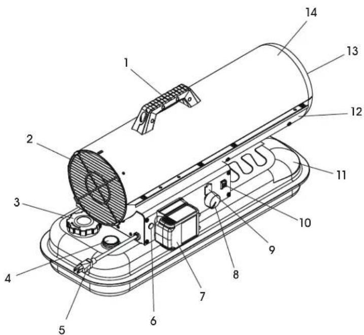
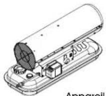
Technical diagram of a device with numbered components for identificationFEATURES
| # DESCRIPTION |
| 1 Handle |
| 2 Fan Guard |
| 3 Fuel Cap |
| 4 Fuel Gauge |
| 5 Power Cord |
| 6 Lamp |
| 7 Battery (Not Included) |
| 8 Thermostat Knob |
| 9 Digital Readout |
| 10 Power/Reset Switch |
| 11 Fuel Tank |
| 12 Lower Shell |
| 13 Hot Air Outlet |
| 14 Upper Shell |
OPERATION
FUELING THE HEATER
Kerosene: For optimal performance of this heater, it is strongly suggested that K-1 kerosene be used, especially in temperatures lower than 26^ F. K-1 kerosene has been refined to virtually eliminate contaminants, such as sulfur, which can cause a rotten egg odor during the operation of the heater. Using diesel fuel can cause excess soot production.

WARNING! Do not use Bio-Diesel as this fuel will damage heater's seals and filter. CSA certified for use with only No. 1 K kerosene fuel. Factory Tested: Kerosene, Diesel #1 and #2, Fuel oil #1 and #2, JP8 (Jet A fuel).

DANGER! Never refuel this heater while it is hot or operating. Fire or explosion could result.

CAUTION! Never fill the fuel tank indoors. Always fill the tank outdoors. Be sure that the heater is on level ground when fueling, and never overfill the tank.

WARNING! Do not use gasoline or crankcase drainings.
- Do not use any fuel that is not approved above.
- Never use fuel such as benzene, alcohol, white gas, camp stove fuel, paint thinners or other oil compounds in this heater. These are volatile fuels that can cause a fire or explosion.
- Never store kerosene in a living space. Kerosene should be stored in a well-ventilated area outside the living area.
- Never store kerosene in direct sunlight or near a source of heat.
- Never use kerosene that has been stored from one season to the next. Kerosene deteriorates over time. Old kerosene will not burn properly in this heater.

NOTE: Kerosene should only be stored in a blue container that is clearly marked "Kerosene". Never store kerosene in a red container. Red is associated with gasoline.

DANGER! Carbon monoxide poisoning may lead to death.
VENTILATION
- Risk of indoor air pollution and carbon monoxide poisoning. Use heater only in well-ventilated areas.
- Refer to "Safety" on page 1 for information about carbon monoxide poisoning.
- Always provide a fresh air opening in the heated space of at least 3 sq. ft. for each 100,000 Btu/Hr. (29 kW) of heater output. Provide a larger opening if more heaters are being used.

NOTE: Minimum ventilation opening needed is 2.4 ft ^4
PRE-LIGHTING INSTRUCTIONS
CHARGE THE BATTERY
Ensure battery is fully charged for best run time. Follow battery manufacturer's instructions for use, charging and storing. Heater does not charge the battery.
OVER DISCHARGE PROTECTION
Heater has a built-in battery protection circuit that will shut the heater off to protect the battery from over-discharging.

CAUTION! Use only Master ^10 approved batteries.
STARTING THE HEATER (IGNITION)
- Fill the tank with kerosene or other approved fuel until needle on fuel gauge points to "F".
- Replace fuel cap and tighten firmly.
- Connect the heater to power source, either approved battery or a three prong (grounded) power source. Use a three prong (grounded) extension cord that is at least 6' long and is a minimum of 14 AWG rating.
- Turn thermostat control knob to desired temperature setting.
- Move the power switch to the "On" position. The power indicator light will illuminate, and heater will ignite.
OPERATION CONTINUED

NOTE: On first ignition or after refueling, unit may make a grinding sound just before ignition. This is the fuel pump removing the air from the fuel line. Heater will start up within seconds. If it does not start, repeat start-up procedures with fuel gauge reading at least 1/2 tank.

NOTE: Smoking may occur on first ignition.

NOTE: The electrical components of these heaters are protected by a fuse mounted in the PC board. If the heater fails to ignite, check this fuse first and replace if necessary. Check the power source to ensure the proper voltage is being provided to the heater.

NOTE: If the heater does not ignite, move switch to "Off" position, check steps 1-3 on page 4 and then move switch to "On" position.
STOPPING THE HEATER (COOL DOWN)
Turn the power switch to the "Off" position. Combustion will stop and the Cooling Cycle will begin and last approximately five minutes. When the Cooling Cycle is complete, the fan will stop running and it will be safe to unplug the heater or disconnect the battery.

NOTE: Unplugging the heater or disconnecting the battery before the Cooling Cycle has been completed may cause overheating or possible damage to the heater and heat plate.
RESTARTING THE HEATER
- Wait 10 seconds after Cooling Cycle has been completed.
- Follow all ignition procedures.
LONG-TERM STORAGE
Use an approved siphon to drain fuel through the fuel cap opening.

IMPORTANT! Never store leftover kerosene or diesel between seasons. Using old fuel can damage heater. Do not disconnect heater from power source before cooling cycle has been completed.

NOTE: If the heater does not ignite, the thermostat may be set too low. Turn the control knob to a higher setting until the heater ignites. If the heater does not ignite, move switch to "Off" position, check steps 1-5 on page 4 and then move switch to "On" position.

DANGER! Risk of fire. Never transport heater with battery attached. Remove battery from heater when not in use.
BATTERY

WARNING! Battery requirements: The batteries (Lithium-ion battery packs) used with this heater must be certified products that comply with local safety regulations.

WARNING! Charger requirements: Use only the charger specified by the battery manufacturer for charging. Charging with another battery pack may cause a fire hazard.

WARNING! Do not ignite or overheat the battery or equipment. It may cause an explosion if it catches fire or is higher than the battery's required limit temperature.

WARNING! It is strictly prohibited to use damaged or illegally modified batteries for this machine as a power source, which may cause fire, explosion, personal injury, property damage and other hazards.

NOTE: This product will not charge the battery. Remove the battery after using the product. If not using for a long time, charge the battery regularly to avoid affecting the battery life.

NOTE: If the existing battery cannot be installed with the device, check local after-sales solution.
| BATTERY RUN TIME ESTIMATED | ||||||
| Battery Voltage 18/20 Volts | ||||||
| Battery Pack Amp Hour 4 5 6 8 9 | 12 | |||||
| Estimated Run Time (Hour)* | 1.7 | 2.1 | 2.6 | 3.4 | 3.9 | 5.1 |
*Note: Actual run time may vary due to battery condition and ambient temperature.
OPERATION CONTINUED

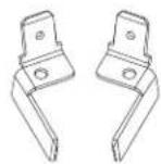
NOTE: If intending to use a Milwaukee Tool® battery, user will need to replace battery connection terminals.
- Ensure heater is not plugged into a power source.
- Locate terminals within the battery connection port. (See Figure 1)
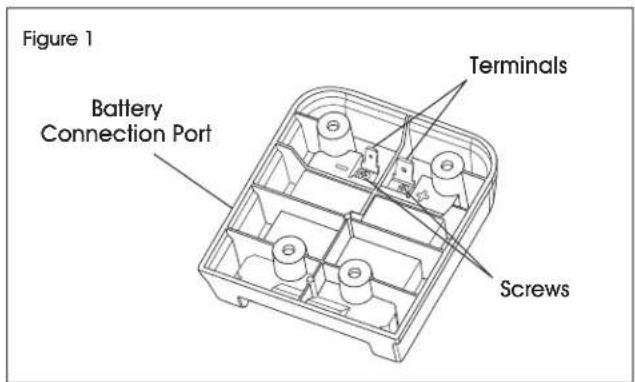
text_image
Figure 1 Battery Connection Port Terminals Screws- Using a Phillips screwdriver, remove screws holding in current terminals by turning the screws counterclockwise. (See Figure 1)
- Replace terminals with terminals provided in the bag. (See Figure 2)
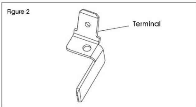
text_image
Figure 2 Terminal- Be sure to tighten screws to ensure a good connection.
BATTERY COMPATIBILITY REFERENCE CHART
| ADAPTER PART # ASM-00040 ASM-00040 ASM-00038 ASM-00039 ASM-00071 | |||||
| Manufacturer Dewalt | * | Milwaukee Tool* | Black + Decker* | Makita* | MasterCraft* |
| Model | 20V Max. and Flexvolt, 18V | M18 20V Max. | 18V 20V Max. | ||
| Technical Spec. (AH) | 4-12 | 4-12 | 4-12 | 4-12 | 4-12 |
| Battery Watt/Hour | 80-240 | 72-216 | 80-240 | 72-216 | 80-240 |
| Battery Models | DCB080DCB200DCB201DCB203BTDCB203GDCB204,DCB204BTDCB205DCB8205GDCB206DCB207DCB208DCB210DCB230DCB240DCB404DCB406DCB609DCB612 | 48-11-181548-11-182048-11-182848-11-183548-11-184048-11-184548-11-185048-11-186048-11-186548-11-189048-11-1812 | LBXR36LBX1540LBXR2036LBX2040LBX2540 | BL1815NBL1820BBL1830BL1830BBL1840BBL1850BBL1860B | 054-3124-0054-7553-4054-7557-6 |
| Battery Certification | UL | UL | UL | UL | UL |
| Battery Charger Models | DCB1106DCB1112 | 48-59-181148-59-181048-59-1802 | BDCA202 | DC18RDC18RA DC18SD | 054-3126-6 |
| Battery Charger Certification | UL | UL | UL | UL | UL |
MAINTENANCE

CAUTION! Do not tamper with the unit. Have a service person make any necessary adjustments or repairs.

NOTE: Use only original equipment parts.
SUGGESTED MAINTENANCE SCHEDULE
FUEL/FUEL TANK
Flush tank every 200 hours of operation or as needed. Do not flush with water; use only fresh K-1 kerosene.

NOTE: Use of diesel fuel may require additional maintenance.
FAN BLADES
Blades should be cleaned at least once per heating season, depending on conditions. Remove all accumulated dust and dirt with a damp cloth, making sure not to bend any of the fan blades. Ensure the blades are dry before restarting the heater.
FUEL FILTER
The fuel filter should be cleaned at least twice per heating season. Clean the filter by rinsing it in clean K-1 Kerosene. Contaminated fuel could make cleaning the fuel filter necessary immediately.

NOTE: To remove the filter from KFA, turn filter 90° counterclockwise. (See Figure 3)
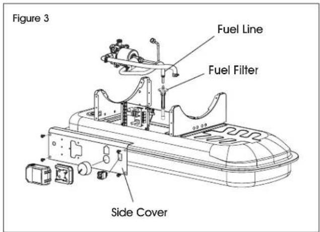
text_image
Figure 3 Fuel Line Fuel Filter Side CoverTHERMISTOR PLACEMENT
Ensure the thermistor wire is in the proper place. The wire should be lying on the bottom shell inside the heater with the plastic end placed under the motor support/motor and away from fan blade.
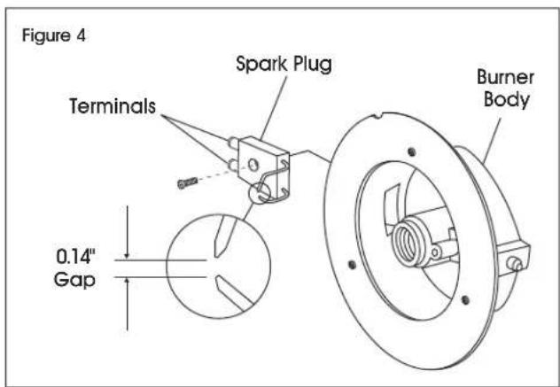
SPARK PLUG
Clean and re-gap every 600 hours of operation or replace as needed. After removing the spark plug, clean the terminals with a wire brush. Re-gap the terminals to 0.14". (See Figure 4)
text_image
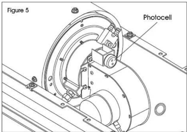
Figure 4 Terminals Spark Plug Burner Body 0.14" GapPHOTOCELL
The photocell should be cleaned using a cotton swab dipped in alcohol or water. Clean at least once per heating season or more depending on conditions. (See Figure 5)
text_image
Figure 5 PhotocellMAINTENANCE CONTINUED
PUMP PRESSURE
While heater is operating, turn adjusting screw clockwise to increase, counterclockwise to decrease pressure. Correct pump pressure is as follows:
| PUMP PRESSURE | |
| Pump Pressure 120 psi (8.27 Bar) | |
| Tolerance +/- 10% | |
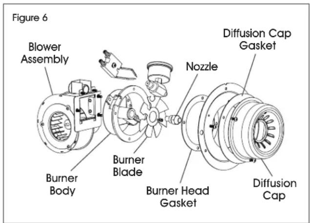
NOZZLE
Nozzle should be cleaned or replaced at least once per heating season. Contaminated fuel could make this necessary immediately. To clean dirt from nozzle, blow compressed air through nozzle front. It may be necessary to soak the nozzle in K-1 kerosene to loosen any dirt particles. (See Figure 6)
text_image
Figure 6 Blower Assembly Burner Body Burner Blade Burner Head Gasket Nozzle Diffusion Cap Gasket Diffusion CapTROUBLESHOOTING
| OPERATING ISSUE CAUSES RECOMMENDATIONS | ||
| Heater Ignites, but main PCB shuts off after a short period of time. Lamp flickers and LED display shows "EI". | Incorrect pump pressure.Dirty fuel filter.Nozzle is dirty.Photocell lens is dirty.Photocell not installed properly.Photocell is defective.Improper electrical connection between main PCB and photocell.Improper location of thermistor sensor.Improper electrical connection within the temperature limit switch. | Adjust pump pressure.Clean or replace fuel filter.Clean or replace nozzle.Clean or replace photocell.Adjust photocell position.Replace photocell.Check wiring connections.Check thermistor placement.Replace temperature limit switch. |
TROUBLESHOOTING CONTINUED
| OPERATING ISSUE CAUSES RECOMMENDATIONS | ||
| Heater will not operate, or motor runs for a short time. Lamp flickers, and LED display shows "E1". | No kerosene in the fuel tank.Incorrect pump pressure.Corroded spark plug or incorrect plug gap.Dirty fuel filter.Dirty nozzle.Moisture in fuel tank.Improper electrical connection between transformer and circuit board.Ignitor wire not connected to spark plug.Defective ignitor. | Fill tank with fresh kerosene.Adjust pump pressure.Clean or replace spark plug.Clean or replace fuel filter.Clean or replace nozzle.Rinse fuel tank with clean, fresh kerosene.Inspect all electrical connections.Re-attach ignitor wire to spark plug.Replace ignitor. |
| Fan does not operate when heater is plugged in, and power switch is in the "ON" position. The lamp is flickering, or LED display shows "E1" or "E2". | Thermostat is set too low.Broken electrical connection between main PCB and motor.Not enough amps available to power heater. | Rotate thermostat to a higher setting.Inspect all electrical connections.Use a new extension cord, or try another electrical socket. |
| Lamp is flickering, and LED display shows "E3". | Thermostat switch has failed. Replace thermostat switch. | |
| Poor combustion and/or excess soot production. | Dirty fuel filter.Poor quality of fuel.PSI is too high or too low.Dirty nozzle. | Clean or replace fuel filter.Flush fuel tank and refuel heater.Use proper pressure.Clean or replace nozzle. |
| Heater does not turn on, and the lamp is not lit. | Temperature limit sensor has overheated.No electrical power.Fuse is blown.Improper electrical connection between temperature limit sensor and circuit board. | Push power switch to "Off" and allow heater to cool for 10 minutes. Restart heater.Check power cords for proper connection, and test the power supply. Ensure battery is fully charged.Check or replace the fuse.Inspect all electrical connections |
ULINE H-110 09
natural_image
Technical line drawing of a cylindrical device with internal components and mounting holes (no text or symbols)PARTES
natural_image
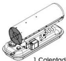
Technical line drawing of a device with a cylindrical component and internal components (no text or symbols)1 Calentador
1 Asa para Transportar

2 Tornillos 15 mm
1 Terminal Dewalt ^® (Preinstalado)
1 Terminal Milwaukee®
SEGURIDAD

| ESPACIO MÍNIMO DE LOS COMBUSTIBLES | |
| Superior 1.20 | m (4 pies) |
| Lateral 1.20 | m (4 pies) |
| Frontal 2.40 | m (8 pies) |
text_image
Technical diagram of a portable electronic device with numbered components for identificationCARACTERÍSTICAS
natural_image
Technical line drawing of a cylindrical device with internal components and mounting base (no text or symbols)PIÈCES
natural_image
Technical line drawing of a device with a cylindrical housing and internal components (no text or symbols)Appareil de chauffage x 1
text_image
Technical diagram of a device with numbered components for identificationCARACTÉRISTIQUES


