H-10295 - Wardrobe Uline - Free user manual and instructions
Find the device manual for free H-10295 Uline in PDF.

User questions about H-10295 Uline
0 question about this device. Answer the ones you know or ask your own.
Ask a new question about this device
Download the instructions for your Wardrobe in PDF format for free! Find your manual H-10295 - Uline and take your electronic device back in hand. On this page are published all the documents necessary for the use of your device. H-10295 by Uline.
USER MANUAL H-10295 Uline
TOOLS NEEDED
Phillips
Screwdriver
Rubber Mallet
Drill
(Optional)
5/16" Drill Bit
(Optional)

Two Person Assembly
Recommended
natural_image
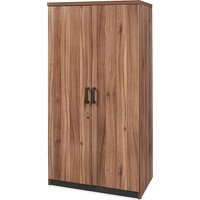
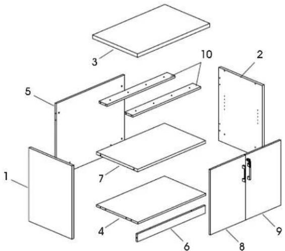
Line drawing of a cabinet with two doors and a handle (no text or symbols)STORAGE CABINET PARTS
text_image
Exploded view diagram of a multi-panel electronic device with numbered components for identification| # DESCRIPTION QTY | |
| 1 Left Side Panel 1 | |
| 2 Right Side Panel 1 | |
| 3 Top Panel 1 | |
| 4 Bottom Panel 1 | |
| 5 Back Panel 1 | |
| 6 Skirt Panel 1 | |
| 7 Shelf 1 | |
| 8 Left Door | 1 |
| 9 Right Door | 1 |
| 10 Support Beam | 2 |
A

Adjustable Glide x 4
B
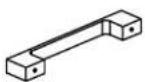
Metal Handle x 2
M4 x 22 mm Bolt x 4
C
M6 x 30 mm Bolt x 8
D
Cam Lock Pin x 17
F

L-Bracket x 1

S-Bracket x 1

M3 x 16 mm Screw x 4
Lock x 1

M3.5 x 14 mm Screw x 2
E

Cam Lock x 17
G
Dowel x 12
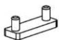
H

Shelf Dowel x 4
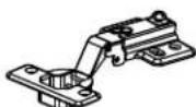
Hinge x 4
|

Cam Lock Cap x 17
K
Door Plug x 1
R
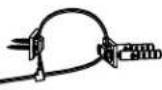
Wall Anchor Kit x 1

M4 x 10 mm Bolt x 8

M4 x 14 mm Screw x 16
ASSEMBLY

For H-10306 and H-10307 storage credenza assembly, refer to instructions included with H-10308 storage credenza top and side frames.

NOTE: Assemble unit on a smooth, non-marring surface to prevent scratching. Check that all parts are included.

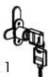
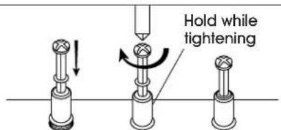
IMPORTANT! Turn cam lock 1/4 to the right to lock.
IMPORTANT! FUNCTION OF CAM LOCK
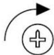
Ensure the arrow is pointing toward edge of panel before inserting into the panel's hole.

IMPORTANT! Cam lock pins must be tightened once inserted into panel. To tighten cam lock pins, grasp lower part of cam lock pin and tighten using a Phillips screwdriver.
text_image
Hold while tighteningTIGHTENING OF CAM LOCK PINS

NOTE: Use Phillips screwdriver to tighten cam locks, cam lock pins and screws.

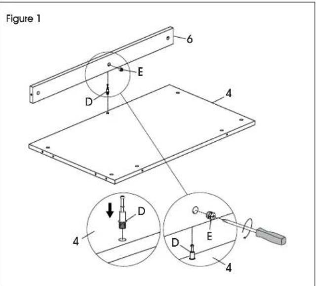
NOTE: Cam lock caps (I) can be applied once cam locks are tightened for a finished look.
- Install one cam lock pin (D) in bottom panel (4). Insert one cam lock (E) into corresponding hole in skirt panel (6). Fit bottom panel and skirt panel together and tighten cam locks. (See Figure 1)
text_image
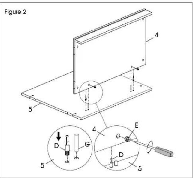
Figure 1 6 E D 4 4 D E D 4- Install two cam lock pins (D) and two dowels (G) in back panel (5). Insert two cam locks (E) into corresponding holes in bottom panel (4). Fit back panel and bottom panel together and tighten cam locks. (See Figure 2)
text_image
Figure 2 4 5 4 E D G D 5ASSEMBLY CONTINUED
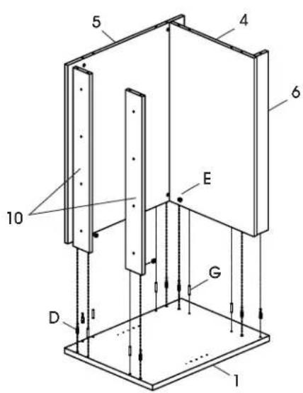
- Install seven cam lock pins (D) and six dowels (G) in left side panel (1). Insert seven cam locks (E) into corresponding holes in back panel (5), bottom panel (4), skirt panel (6) and top support beams (10). Fit left side panel together with back panel, bottom panel, skirt panel and top support beams and tighten cam locks. Repeat for right side panel (2). (See Figure 3)
Figure 3
text_image
5 4 6 E 10 G D 1- Align holes on L-bracket (F) with pre-drilled holes in top panel (3). Insert two M3 x 16 mm screws (F) and attach using a Phillips screwdriver or drill. Align holes on door plug (K) with pre-drilled holes in top panel and gently tap with a rubber mallet to insert. (See Figure 4)
Figure 4
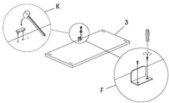
text_image
Technical diagram showing mechanical assembly with labeled parts K, F, and numbered components 3 and 4- Attach top panel (3) to support beams using eight M6 x 30 mm bolts (C). (See Figure 5)
- Mount adjustable glides (A) to bottom of side panels. (See Figure 5)

NOTE: Glides can be adjusted to compensate for uneven floors.
Figure 5
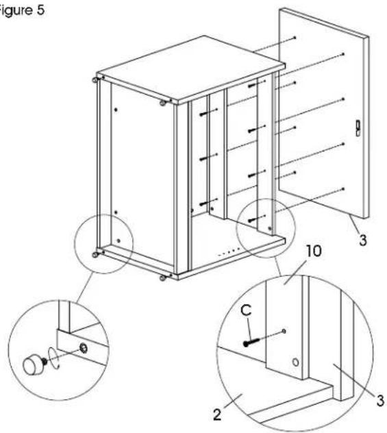
text_image
Figure 5 10 C 2 3 3- Set cabinet upright. Insert four shelf dowels (H) into corresponding holes in side panels (1, 2). Place shelf (7) inside cabinet and ensure shelf supports lower onto shelf dowels. Tighten shelf supports in underside of shelves for a secure fit. (See Figure 6)
Figure 6
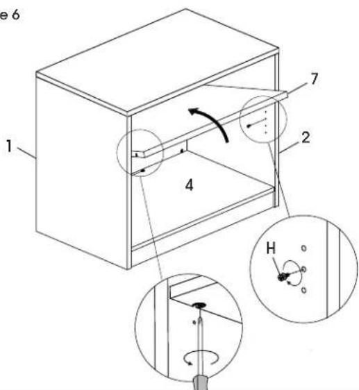
text_image
e 6 1 2 4 7 HASSEMBLY CONTINUED
- Place left door (8) and right door (9) panels on a smooth, non-marring surface to prevent scratching. Align holes in hinge (J) with pre-drilled holes in door panels. Insert two M4 x 10 mm bolts (J) and tighten. Repeat for three remaining hinges. (See Figure 7)
- Attach handles (B) to the outside of the door panels using four M4 x 22 mm bolts (B). (See Figure 7)
- Align holes on S-bracket (F) with pre-drilled holes in top of left door (8). Insert two M3 x 16 mm screws (F) and tighten. (See Figure 7)
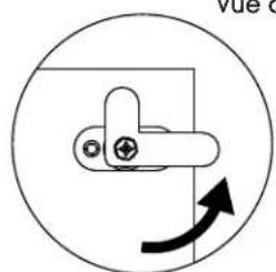
- Align holes on lock (F) with pre-drilled holes in right door. Insert two M3.5 x 14 mm screws (F) and tighten. (See Figures 7-8)

NOTE: Refer to Figure 8 for correct orientation of lock.
Figure 7
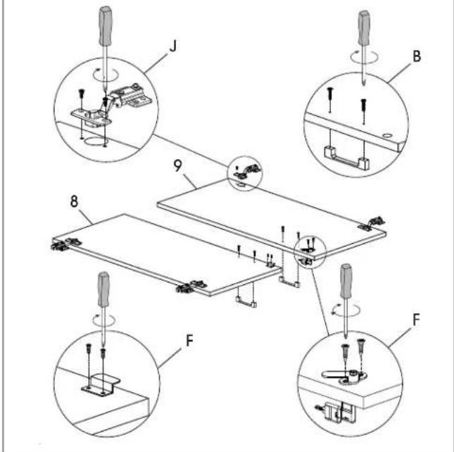
text_image
J B 9 8 F FFigure 8
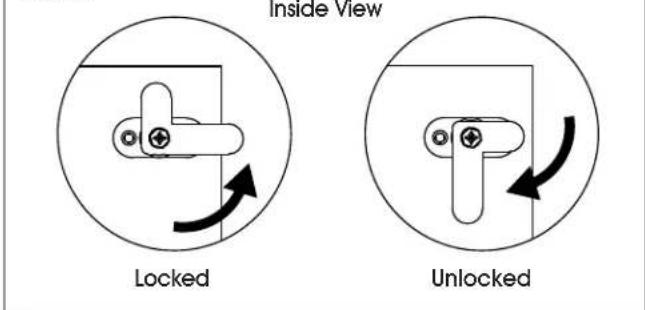
text_image
Inside View Locked Unlocked- Using two people, hold door panel in line with side panel. Attach hinge (J) to inside of side panels using four M4 x 14 mm screws (J). Repeat for three remaining hinges. (See Figure 9)

NOTE: Side panels include pre-drilled holes for alignment. Attach doors using the pre-drilled holes first. Remaining wood screws can be installed without pre-drilling holes in the side panel.
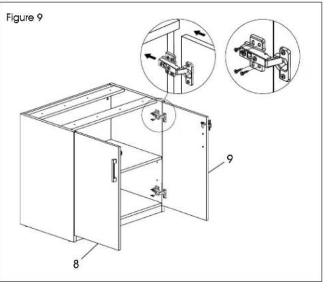
text_image
Figure 9 8 9- Once door panels are attached, hinge may need to be adjusted to align the doors. To adjust the depth of the doors, tighten or loosen the rear screw in the hinge. To adjust the angle of the doors, tighten or loosen the center screw in the hinge. (See Figure 10)
Figure 10
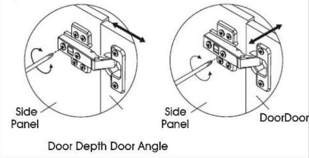
text_image
Side Panel Door Depth Door Angle Side Panel DoorDoorASSEMBLY CONTINUED
- Attach one bracket of wall anchor (R) to back of top of cabinet using two M4 x 20 mm screws. Mark holes on wall where plastic anchors will be located. Drill holes using 5/16" drill bit. Mount remaining bracket of wall anchor to wall with two M4 x 40 mm screws and two plastic anchors. Tighten cable tie to prevent tipping. Repeat for remaining side of storage cabinet. (See Figure 11)
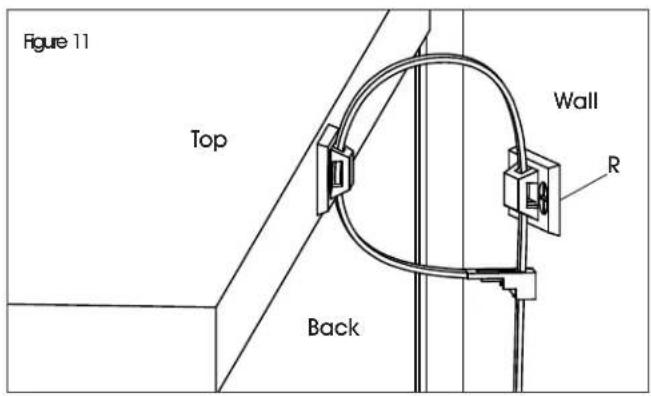
text_image
Figure 11 Top Back Wall R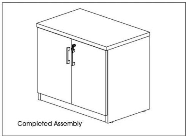
natural_image
Line drawing of a completed cabinet with a handle and top panel, labeled 'Completed Assembly' (no other text or symbols)
natural_image
Line drawing of a cabinet with two doors and a handle (no text or symbols)text_image
Exploded view diagram of a multi-panel electronic device with numbered components for identificationtext_image
5 4 6 E 10 G D 1natural_image
Line drawing of a cabinet with a handle and label 'Ensamble Terminado' (no other text or symbols)
natural_image
Line drawing of a cabinet with two doors and a handle (no text or symbols)OUTILS REQUIS
Tournevis cruciforme
text_image
Exploded view diagram of a modular device with numbered components for identificationtext_image
Figure 1 6 E D 4 4 D E D 4text_image
Figure 2 4 5 4 E D G D 5MONTAGE SUITE
text_image
5 4 6 E 10 G D 1text_image
Technical diagram showing mechanical assembly steps with labeled components and circular insets for inspection or testing.Figure 8
natural_image
Pure mechanical diagram showing a lever mechanism with an arrow indicating rotational motion (no text or symbols)Verrouillé
Vue de l'intérieur
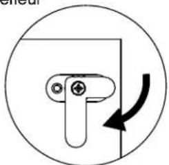
natural_image
Simple line drawing of a mechanical component with an arrow indicating rotation (no text or symbols)Déverrouillé