H-5780 - Electric heating Uline - Free user manual and instructions
Find the device manual for free H-5780 Uline in PDF.

User questions about H-5780 Uline
0 question about this device. Answer the ones you know or ask your own.
Ask a new question about this device
Download the instructions for your Electric heating in PDF format for free! Find your manual H-5780 - Uline and take your electronic device back in hand. On this page are published all the documents necessary for the use of your device. H-5780 by Uline.
USER MANUAL H-5780 Uline
natural_image
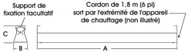
Technical line drawing of a rectangular mechanical component with mounting holes and a cable (no text or symbols)SPECIFICATIONS
text_image
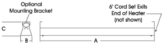
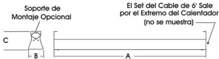
Optional Mounting Bracket C B A 6' Cord Set Exits End of Heater (not shown)
NOTE: For indoor (excluding residences) and outdoor applications.

WARNING! Explosion and fire hazard! Serious injury or death may occur.
| Housing 24 ga. Galvannealed | |
| Finish Brown Powder Coat | |
| Reflectors, End Caps 0.04" Gold Anodized Aluminum | |
| Suspension Adjustable Mounting Bracket or Chain | |
| Voltage 120V | |
| Cord Set Plug | NEMA 5-15P |
| Matching Receptacle | NEMA 5-15R |
- Do not use in locations containing hazardous atmospheres.
- Do not use inside residences.
QUARTZ TUBE INSTALLATION

WARNING! Electrical shock hazard! Serious injury or death may occur.
- Disconnect from electrical supply before installing or servicing this heater.
- Reflector end caps must be installed prior to powering the unit; refer to step 3.

CAUTION! Install heater so quartz tube is horizontal. Failure to do this may cause the heating element within the tube to sag and cause premature burnout.
Each heater is equipped with two high-temperature silicone lead wires and a ground termination. Ensure power source conforms to the heater requirements. Only use quartz tube included with heater.
- Insert quartz tube into L-shaped slots in heater housing.
- On each end of the quartz tube, place one lead wire ring terminal, one lock washer and one hex nut on the threaded stud and tighten securely. (See Figure 1) Lock washers and hex nuts are provided in the hardware package.

NOTE: Use a second wrench to hold the inner hex nut in place while tightening the outer hex nut.

CAUTION! Failure to securely tighten this connection will cause the element to fail prematurely.
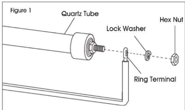
text_image
Figure 1 Quartz Tube Lock Washer Hex Nut Ring Terminal- Attach reflector end caps to both ends of housing using the four screws provided in the hardware package.
HEATER INSTALLATION
Figure 2
text_image
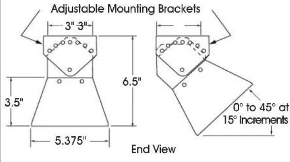
Adjustable Mounting Brackets 3" 3" 6.5" 3.5" 5.375" End View 0° to 45° at 15° IncrementsFigure 3
text_image
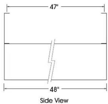
47" 48" Side ViewFigure 4
text_image
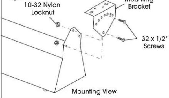
10-32 Nylon Locknut Mounting Bracket 32 x 1/2" Screws Mounting ViewFigure 5
natural_image
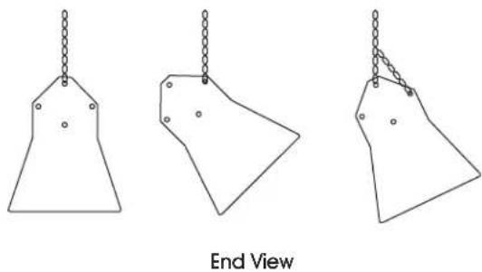
Three hand-painted geometric shapes with chain links, labeled 'End View' below (no text or symbols on shapes)STOP
WARNING! Fire hazard! Serious injury or death may occur.
- Read and follow clearances shown below for all heater installations.
• Do not use inside residences.
MINIMUM INSTALLATION CLEARANCES

NOTE: Heater must be installed as follows:
- 12" minimum from a vertical surface.
- 72" from any combustible material.
• 3" minimum from the ceiling. - 36" minimum from other heaters.

NOTE: For optimum spot heating performance, it is recommended that the distance from the floor should be approximately 7-9 feet.
SUSPENSION ALTERNATIVES
Heater can be mounted with either the adjustable mounting brackets or by chain suspension. Both mounting options are included with the heater in the hardware package.
STANDARD MOUNTING
Two adjustable mounting brackets and fastening hardware are included in hardware package. Using the mounting centers specified in Figures 2-3, mount the adjustable mounting brackets (bends to the inside). Once mounted, assemble the heater to brackets with mounting hardware. (See Figure 4) These brackets enable the heater to be angled in 15° increments up to 45°.
CHAIN SUSPENSION
The heater can also be chain-hung as shown in Figure 5. Cut the 16 ga. chains (two 4-foot chains are provided) to desired length. Attach chains to heater with S-hooks provided and suspend from overhead structure. Crimp S-hooks closed after assembly.

CAUTION! Install heater so quartz tube is horizontal. Failure to do this may cause the heating element within the tube to sag and cause premature burnout.

WARNING! Electrical shock hazard. Serious injury or death may occur.
- Disconnect from electrical supply before installing or servicing this heater.
- Read and follow installation clearance requirements listed above.
WIRING
INTERNAL WIRING DIAGRAM
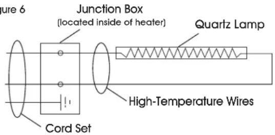
Heater is equipped with two high-temperature silicone lead wires and a ground termination.
Figure 6
text_image
Figure 6 Junction Box (located inside of heater) Quartz Lamp High-Temperature Wires Cord SetSTOP
WARNING! Electrical shock hazard! Serious injury or death may occur.
- Disconnect from electrical supply before installing or servicing this heater.
- Read and follow all safety information at right.
-
Ensure the power source conforms to the specifications on the heater label.
-
Do not depend on a thermostat or other switch as the sole means of disconnecting power when installing or servicing the heater. Always unplug the cord set or open the safety switch and lock it open.
- All wiring must be performed by a licensed electrician.
- The cord sets supplied with these heaters are equipped with provisions for proper grounding. Always mate the cord set plug with the proper grounded receptacle in accordance with the National Electric Code and all local governing codes and ordinances.

CAUTION! Do not use an extension cord to provide power to heater.

WARNING! Never connect the green or green-yellow wire to a live conductor.
MAINTENANCE

CAUTION! Always disconnect heater from power source before performing any maintenance or service.
Periodically clean the reflector with a dampened soft cloth using a mild detergent. Rinse with water and wipe dry with a clean soft cloth.
TROUBLESHOOTING
| OPERATING ISSUE CAUSES RECOMMENDATIONS | ||
| Element does not energize. | Defective element.Improper connection. | Replace element.Check connection to power outlet. |
| Not enough heat. | Heater too small for application.Heater mounted too high or too far. | Add additional heater(s).Decrease mounting height or distance. |
| Too much heat. | Heater too large for application.Heater mounted too low or too close. | Replace with smaller heater.Increase mounting height or distance. |
| Hot spot in tube | Heater is not level.Grease or moisture on tube. | Adjust to a level mount.Clean tube. Replace if problem persists. |
ULINE
1-800-295-5510
uline.com
ESPECIFICACIONES
natural_image
Technical line drawing of a cylindrical mechanical component with mounting holes and a cable (no text or symbols)SPÉCIFICATIONS