
H-11721 - Air Conditioning Uline - Free user manual and instructions
Find the device manual for free H-11721 Uline in PDF.

User questions about H-11721 Uline
0 question about this device. Answer the ones you know or ask your own.
Ask a new question about this device
Download the instructions for your Air Conditioning in PDF format for free! Find your manual H-11721 - Uline and take your electronic device back in hand. On this page are published all the documents necessary for the use of your device. H-11721 by Uline.
USER MANUAL H-11721 Uline
ULINE H-11188, H-11721
ECONOMY EVAPORATIVE COOLER
1-800-295-5510
uline.com
natural_image
Line drawing of a portable air conditioner unit with ventilation grilles and wheels (no text or symbols)TOOL NEEDED
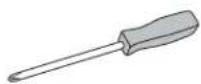
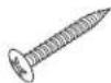
Phillips Screwdriver
PARTS
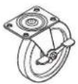


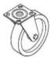
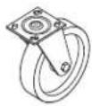
Hose Adapter x 1 Screw x 16Swivel Caster x 2Locking Caster x 2
SAFETY
- Read and follow all instructions, cautions and warnings. Failure to do so could result in personal injury, death or property damage.
- Unit must be in "OFF" position and unplugged from power receptacle before performing any maintenance or service or before removing access panels.
- Ensure electrical power source conforms to local codes and evaporative cooler requirements.
- Do not touch electrically live components.
- Ensure all power cords do not touch sharp edges, hot surfaces or chemicals. Immediately replace damaged parts.
• Never leave unit unattended.
- Continuous fill should not be used indoors or unattended.
• After unpacking, carefully inspect for any damage that may have occurred during transit.
- Inspect for loose, missing or damaged parts.
- Wheels and hardware are located in a compartment on the bottom side of cooler.
- Contact Uline Customer Service at 1-800-295-5510 to request replacement parts if any parts are missing.
SETUP
CASTER INSTALLATION
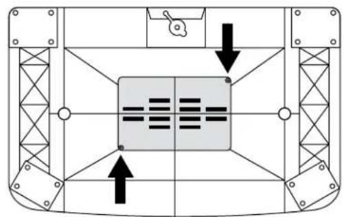
- Lay unit upside down. Remove screws and panel on bottom of unit using Phillips screwdriver. (See Figure 1)
Figure 1
natural_image
Top-down schematic of a mechanical or structural component with internal grid and directional arrows (no text or symbols)- Remove all parts (casters, hose adapter, hardware) from compartment. Replace compartment cover when finished.
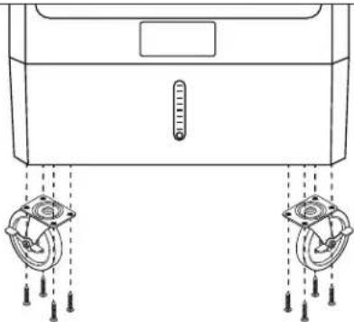
- Install casters using Phillips screwdriver and four screws per caster. (See Figure 2)

NOTE: Ensure locking casters are installed at front of unit.
natural_image
Line drawing of a washing machine with two wheels and a thermometer, no text or symbols presentFigure 2
FILLING THE TANK

NOTE: Unit must be in an upright and level position before filling.
HOSE FILL

NOTE: Do not use hose adapter indoors.
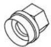
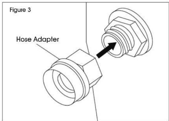
- Connect hose adapter to plastic grommet on bottom left side of unit. Rotate hose adapter clockwise to secure. (See Figure 3)
text_image
Figure 3 Hose Adapter- Connect a standard garden hose to hose adapter.
- Turn water on low to fill tank. Once tank is 1/4 full, the float will stop the flow of water.
MANUAL FILL
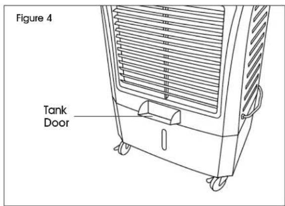
- Press in on center of tank door to open. (See Figure 4)
text_image
Figure 4 Tank Door- Fill tank with up to 10 gallons of water. Repeat step 1 to close door.
OPERATION
STARTING PUMP AND FAN

NOTE: Ensure tank is full before turning on.

NOTE: Ensure caster brakes are engaged.
- Turn pump switch to "ON" position. Water will begin to flow down to media pads.
- Turn fan switch to desired speed.
MAINTENANCE
CLEANING
The removable panel and pads can be gently sprayed off to remove build-up. A soft bristle brush may also be used.

NOTE: Never spray pads with water while cooler is in operation. This may damage motor and void warranty.

NOTE: Vinegar is recommended for cleaning and can be periodically cycled through during normal use.
BACK PANEL REMOVAL
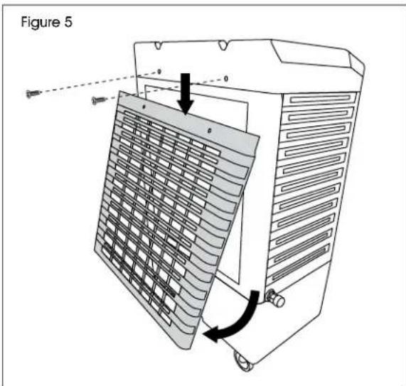
- Disconnect unit from power supply. Remove two Phillips screws from upper back side of cooler. (See Figure 5)
- Pull panel down and pull bottom out to remove. (See Figure 5)
text_image
Figure 5REMOVAL OF RIGID MEDIA
Once back panel is removed, media pads will be accessible.

NOTE: Some pads may be held in place with pins. Remove to free pads.
STORAGE
Ensure pads are dry by running fan without pump for at least 30 minutes.

IMPORTANT! Always drain tanks and wipe dry before storing.
TROUBLESHOOTING
| OPERATING ISSUE RECOMMENDATIONS | |
| Cooler will not turn on. Ensure unit is plugged in and switched on.Receptacle breaker may need to be reset.Reset GFCI plug if applicable.Ensure timer is off.Unit may need on/off switch replacement. | |
| Fan will not operate. Ensure fan is on.Ensure blades are not obstructed.Replace fan motor/switch. | |
| Fan is running slow. Capacitor may need to be replaced. | |
| Cooler does not pump. Ensure pump switch is "ON".Add water if water level is low.Ensure hoses are connected and free of debris.Replace pump.Replace pump switch. | |
| Swing does not work. Ensure swing switch is "ON".Ensure linkage is connected.Replace oscillation switch.Replace oscillation motor. | |
| Water is leaking. Ensure drain plug is securely in place.Ensure cooler is level.Inspect tank for cracks.Check media pads for water running outside of unit.Check hose connections for leaks.Check spreaders for build up. This may cause spillover into airstream. | |
| Water level high or low. Adjust nut on float valve.Replace float valve. |
ULINE H-11188, H-11721
natural_image
Line drawing of a portable air conditioner unit with cooling fins and wheels (no text or symbols)PARTES

natural_image
Diagram of a mechanical device with two circular components and a thermometer, no text or symbols presentDiagrama 2
LLENAR EL TANQUE

natural_image
Line drawing of a portable air conditioner unit with cooling fins and wheels (no text or symbols)PIÈCES


natural_image
Top-down schematic of a mechanical or structural component with internal grid and directional arrows (no text or symbols)natural_image
Line drawing of a device with two circular components and a thermometer, no text or symbols presentFigure 2
REMLISSAGE DU RÉSERVOIR


