
SRI990 - Industrial measuring instrument SCHNEIDER - Free user manual and instructions
Find the device manual for free SRI990 SCHNEIDER in PDF.

| Product Type | Analog positioner for servomotor |
| Brand | Schneider |
| Model | SRI990 |
| Input signal | 4-20 mA |
| Analog output (position feedback) | 4-20 mA, two-wire technology (option Q) |
| Pneumatic supply | Supply air 1.4 to 6 bar, clean, oil-free, dust-free and water-free air |
| Electrical supply (inductive limit switches) | 8 V DC |
| Working range | ±45° around the center position |
| Mounting | On linear (NAMUR, direct) or rotary servomotors |
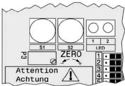
| Adjustments | Zero (P3), stroke (P2), gain (P4), rotation direction (micro-switch 1+2) |
| Limit switches | Two-wire inductive sensors according to DIN 19234 or NAMUR; micro contacts (option V) |
| Micro-switch configuration | 8 micro-switches: rotation direction, input signal, measuring range |
| Position transmitter | Configuration via push buttons S1/S2 for 4 mA and 20 mA |
| Maintenance | Check the cleanliness of the supply air; no parts requiring regular maintenance in the manual |
| Safety | Observe documents EX EVE0001, PSS EVE0105 and MI EVE0105 |
| Related documents | Complete user manual and technical data sheets available online |
Frequently Asked Questions - SRI990 SCHNEIDER
User questions about SRI990 SCHNEIDER
0 question about this device. Answer the ones you know or ask your own.
Ask a new question about this device
Download the instructions for your Industrial measuring instrument in PDF format for free! Find your manual SRI990 - SCHNEIDER and take your electronic device back in hand. On this page are published all the documents necessary for the use of your device. SRI990 by SCHNEIDER.
USER MANUAL SRI990 SCHNEIDER
SRI990 Analog Positioner

natural_image
Blue industrial control box with yellow internal component and two pressure gauges (no visible text or symbols)Quick Guide ..... (English)
These instructions are to be used as a guide for quick start-up. For more detailed information please refer to the standard documents "Master Instructions" and "Product Specification Sheet". These can be found on our Website.
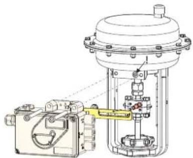
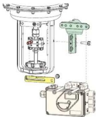
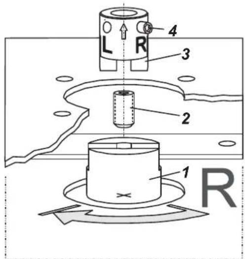
1. Mounting to actuators
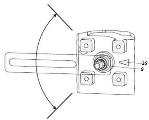
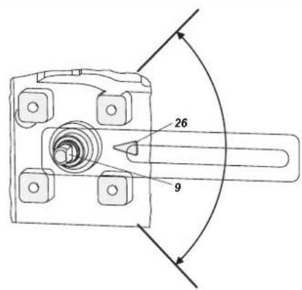
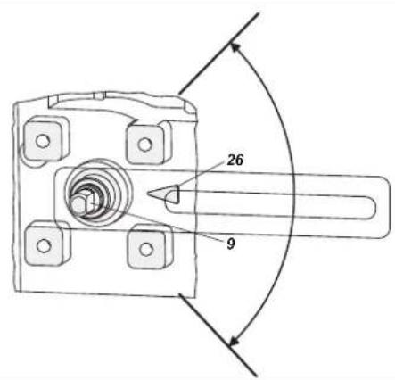
During operation the flat side of the spindle 9 on the back of the positioner must always point towards the arrow 26. The working angle around this position is ± 45°

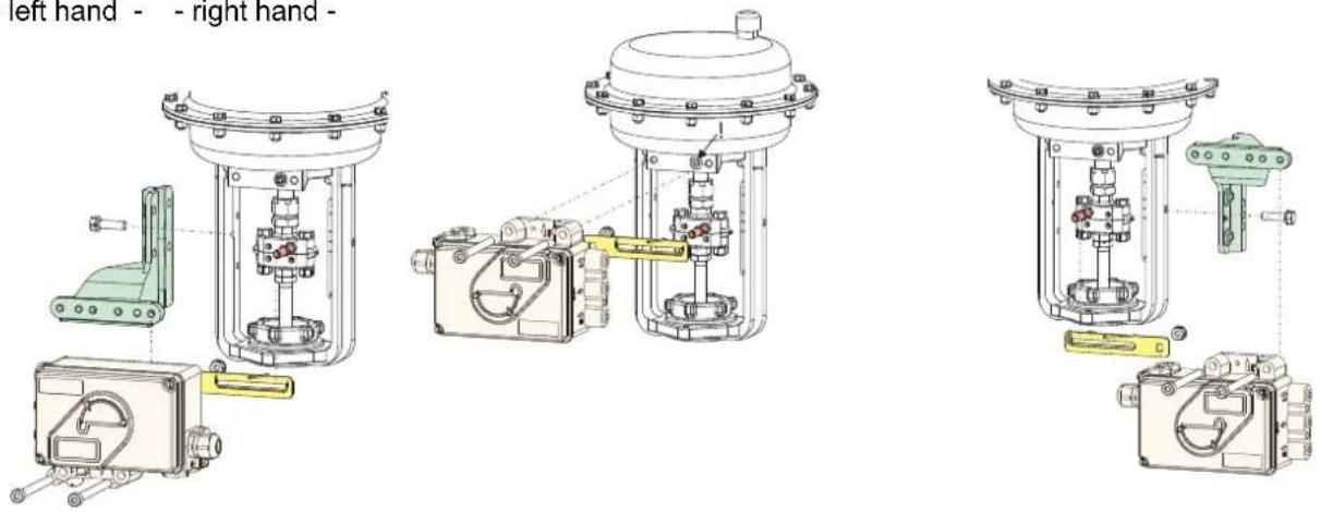
1.1 Mounting to linear actuators
NAMUR mounting Direct mounting NAMUR mounting - left hand - - right hand -
Feedback lever for linear actuators:
The carrier bolt B is in the slot of the feedback lever A and the compensating spring F touches the carrier bolt.
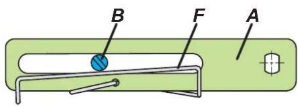
Carrier bolt B:
1 threaded sleeve
2 Stud
3 coupling piece

Life Is ⏻n
Foxboro™
by Schneider Electric
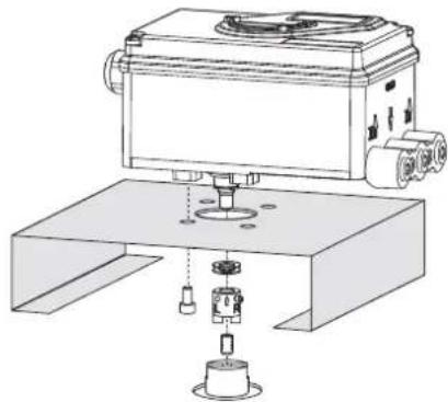
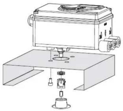
1.2 Mounting to rotary actuators
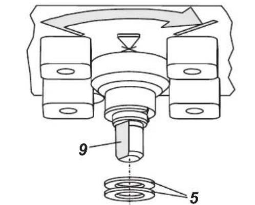
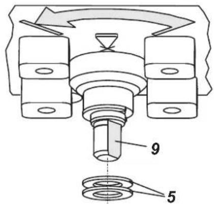
- Do not tighten grub screw 4 against the thread of spindle 9!
- When in use the flat side of the spindle 9 must move (0 ↔ 100%) in front of the arrow 26.
- When the product temperature rises, the drive shaft 1 increases in length. Therefore, the rotary adaptor 3 must be mounted so that approx. 1mm (0.04 in.) of clearance results between the drive shaft 1 and the rotary adaptor 3. This is achieved by placing an appropriate number of washers 5, on the feedback spindle 9, before attaching the rotary adaptor. Two washers should result in a clearance of 1mm
natural_image
Technical line drawing of a mechanical testing setup with a box, base platform, and clamping device (no text or symbols)Actuator, left turning
Actuator, right turning
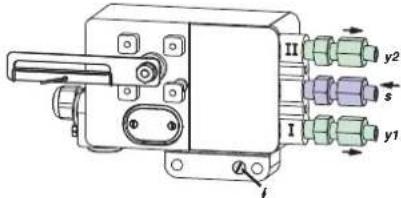
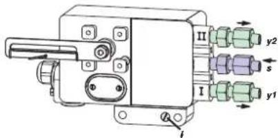
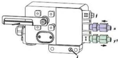
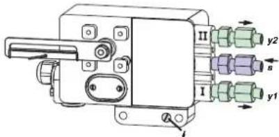
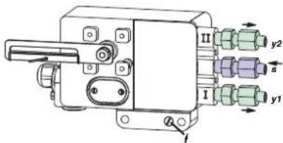
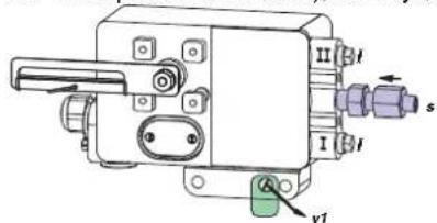
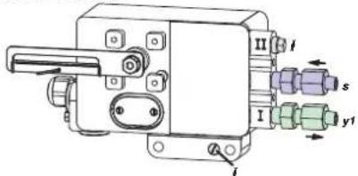
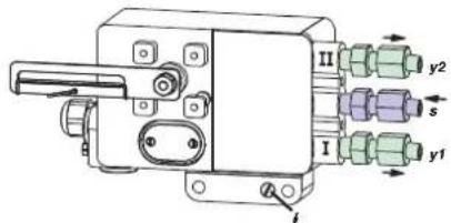
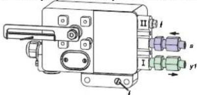
2 Pneumatic connections
Air supply (s): 1,4 to 6 bar (but not more than the max. pressure of actuator), free of oil, dust and water!

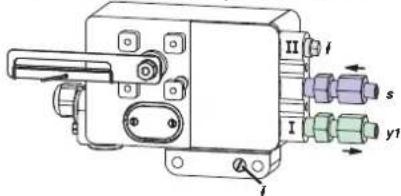
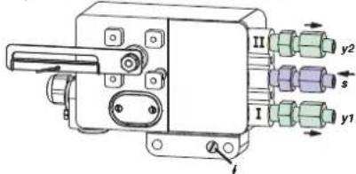
Single acting, direct mounting Single acting Double acting air supply y1, y2 pneumatic outputs (--) closed
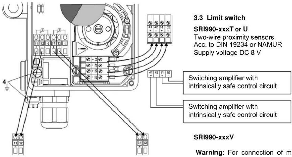
3. Electrical connections
The safety requirements of document EX EVE0001 as well as the requirements of PSS EVE0107 and MI EVE0107 for SRI990 must be observed!
3.1 Setpoint

Input 4 to 20 mA
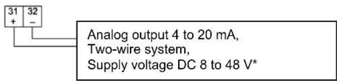
3.2 Position feedback 4-20 mA (SRI990-xxQ)
3.3 Limit switch
SRI990-xxxT or U
Two-wire proximity sensors, Acc. to DIN 19234 or NAMUR Supply voltage DC 8 V
Switching amplifier with intrinsically safe control circuit
Switching amplifier with intrinsically safe control circuit
SRI990-xxxV
Warning: For connection of micro switches please refer to MI (Master Instruction) and respect the safety requirements described in document EX EVE0001.
4 START UP (setting by means of local switches and potentiometers)
4.1 Initial setting
After mounting the positioner on the actuator, air and electrical input connected, proceed as follow.
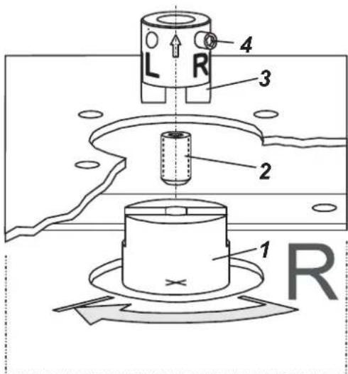
First all switches must be in position I. This is the setting for Input signal "4 to 20 mA" and "Left mounted" (counter clockwise rotation).
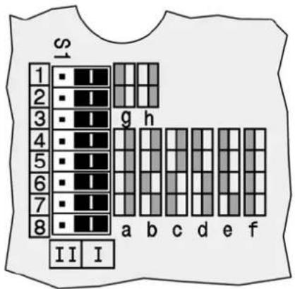
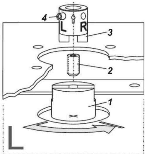
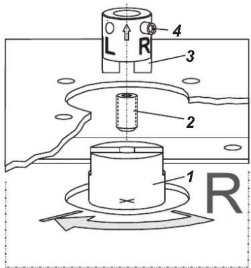
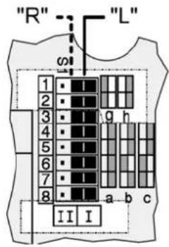
4.2 Configuration direction of rotation of feedback shaft
Defined as direction of rotation of feedback shaft from the start to the end position, looking at the positioner from the
front. Switch 1+2 to "R" if necessary. R= right turn (clockwise) L= left turn (counter cw)
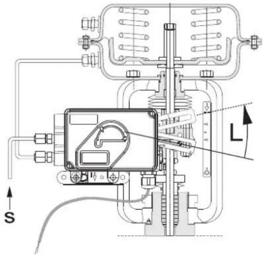
4.3 Setting of zero, span and gain
a) Apply 4 mA to Input.
b) Turn potentiometer P3 for zero point (ZERO) until actuator just begins to move from its end position.
Rotation P3 to the right: zero point is increased
Rotation P3 to the left: zero point is reduced
c) Apply 20 mA to Input
d) Turn potentiometer P2 for span (S) until actuator exactly reaches its end position.
Rotation P2 to the right: span is increased
Rotation P2 to the left: span is reduced
e) The loop amplification of the positioner is set via potentiometer P4. Trim the gain so that the actuator will not swing at constant given input value.
f) Re-check zero and span settings.
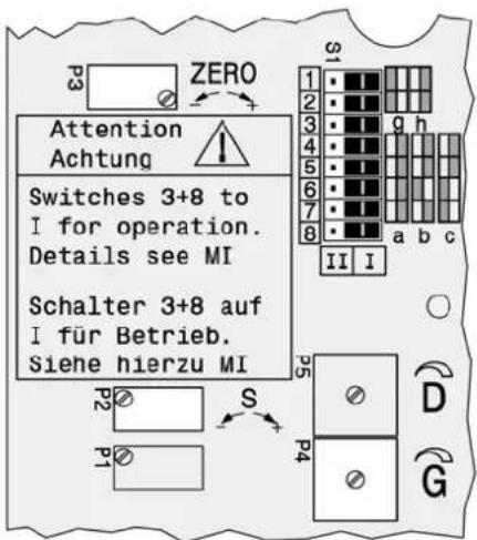
5 Setting and Start Up of position transmitter 4-20mA
The electronic connection of the position transmitter must be assured. Both LED's are then light up.
Adjusting the start of the measuring range (4mA)
a) Move the actuator to the starting position.
b) Press push button S1 „Config Output 4mA“ longer than 2 seconds. During this time LED 1 lights up. After 2 seconds both LED's are light up again, the value for 4mA is stored.
Adjusting the end of the measuring range (20mA)
a) Move the actuator to the end position.
b) Press push button S2 „Config Output 20mA“ longer than 2 seconds. During this time LED 2 lights up. After 2 seconds both LED's are light up again, the value for 20mA is stored.

1.1 Montage an Linearantriebe
natural_image
Technical diagram of a mechanical assembly with no visible text or symbols
natural_image
Technical diagram of a mechanical assembly with internal components and mounting features (no visible text or labels)by Schneider Electric
natural_image
Technical line drawing of a mechanical testing setup with a central device and base platform (no text or symbols)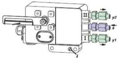
by Schneider Electric
Invensys Systems, Inc.
38 Neponset Street
Foxboro, MA 02035
United States of America
schnider electric.com
Global Customer Support
Toll free: 1-866-746-6477
Global: 1-508-549-2424
Website:
http://support.ips.invensys.com
Copyright 2010-2016 Invensys Systems, Inc. All rights reserved. Invensys, Foxboro, and I/A Series are trademarks of Invensys Limited, its subsidiaries, and affiliates. All other trademarks are the property of their respective owners.
DOKT 536 022 055
FD-QG-PO-004-DE
0316

natural_image
Technical diagram of mechanical assembly with labeled components (no text or symbols present)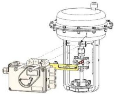
natural_image
Technical line drawing of a mechanical valve assembly with no visible text or symbols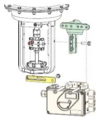
natural_image
Technical diagram of a mechanical device with internal components and mounting features (no visible text or labels)by Schneider Electric
natural_image
Technical line drawing of a mechanical testing setup with a central device and base mount (no text or symbols)
natural_image
Technical line drawing of mechanical components including a bracket, housing, and mounting bracket (no text or labels)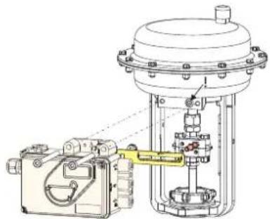
natural_image
Technical line drawing of a mechanical assembly with no visible text or symbols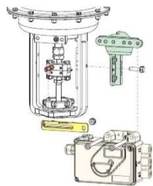
natural_image
Technical diagram of a mechanical assembly with internal components and exploded view (no text or labels)by Schneider Electric
natural_image
Technical line drawing of a mechanical device with base, clamping mechanism, and housing (no text or symbols)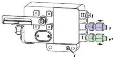

by Schneider Electric
natural_image
Technical line drawing of a mechanical testing setup with a central device and base mount (no text or symbols)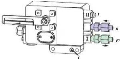

Copyright 2010-2016 Invensys Systems, Inc. All rights reserved.
Invensys, Foxboro, and I/A Series are trademarks of Invensys Limited, its subsidiaries, and affiliates. All other trademarks are the property of their respective owners.
DOKT 536 022 134
FD-QG-PO-004-ES
natural_image
Technical diagram of a mechanical assembly with components like a clamp, housing, and housing unit (no visible text or labels)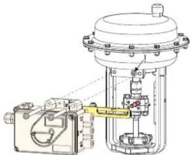
natural_image
Technical line drawing of a mechanical assembly with no visible text or symbols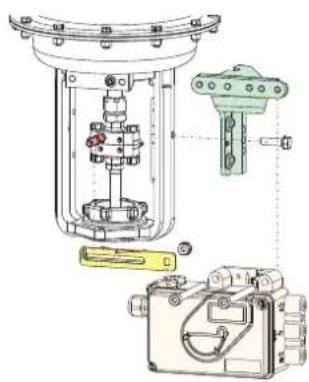
natural_image
Technical diagram of a mechanical assembly with internal components and mounting base (no text or labels)by Schneider Electric
natural_image
Technical line drawing of a mechanical device with mounting base and control panel (no text or symbols)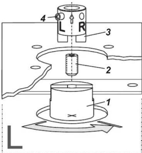
natural_image
Technical diagram of mechanical assembly with exploded view and component layout (no visible text or labels)Прямой монтаж
natural_image
Technical line drawing of a mechanical device with no visible text or symbolsМонтаж по NAMUR
- правосторонний -
natural_image
Technical diagram of a mechanical assembly with no visible text or symbolsnatural_image
Technical line drawing of a mechanical testing setup with a device and base (no text or symbols)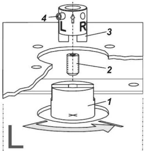
Простое действие
Двойное действие
by Schneider Electric
Invensys Systems, Inc.
38 Neponset Street
Foxboro, MA 02035
United States of America
schneider-electric.com
Global Customer Support
Toll free: 1-866-746-6477
Global: 1-508-549-2424
Website:
http://support.ips.invensys.com
Copyright 2010-2016 Invensys Systems, Inc. All rights reserved.
Invensys, Foxboro, and I/A Series are trademarks of Invensys Limited, its subsidiaries, and affiliates. All other trademarks are the property of their respective owners.
DOKT 536 022 134
FD-QG-PO-004-RU
SRI990 Analogni pozicioner
Ovo uputstvo je namenjeno za brzi start-up pozicionera. Za detaljnije informacije pogledajte standardne dokumenta "Master Instructions" (Glavno, sveobuhvatno uputstvo) i "Product Specification Sheet" (Specifikacija Proizvoda). Ovi dokumenti se mogu pronaći na našim web stranicama.
1. MONTIRANJE NA AKTUATORE

1.1 MONTIRANJE NA LINEARNE AKTUATORE
NAMUR montiranje direktno montiranje - sa leve strane - - sa desne strane -
NAMUR
montiranje
natural_image
Technical diagram of a mechanical assembly with exploded view and component details (no text or labels)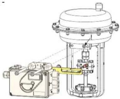
natural_image
Technical line drawing of a mechanical device with no visible text or symbols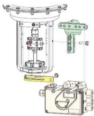
natural_image
Technical diagram of a mechanical assembly with internal components and mounting base (no visible text or labels)Poluga povratne sprege za linearne aktuatore:
by Schneider Electric
1.2 MONTIRANJE NA ROTACIONE AKTUATORE
• Nemojte pritezati bezglavi zavrtanj 4 prema navoju osovine 9!
• Kada se koristi, ravna strana osovine 9 se mora kretati (0 ↔ 100%) naspram strelice 26.
- Kada se povećava temperatura pozicionera, pogonska osovina 1 se izdužuje. Prema tome, rotacioni adapter 3 mora biti montiran tako da ukupni zazor između pogonske osovine 1 i rotacionog adaptera 3 iznosi aproksimativno 1 mm (0,04 in.). To se postiže postavljanjem odgovarajućeg broja podmetača 5, na osovinu povratne sprege 9, pre postavljanja rotacionog adaptera. Dva podmetača će rezultirati zazorom od oko 1 mm.
natural_image
Technical line drawing of a mechanical testing setup with a central device and base platform (no text or symbols)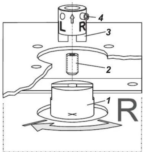
2 PNEUMATSKI PRIKLJUČCI
Napajanje instrumental gasom (s): 1,4 do 6 bar (ali ne više od max. pritiska aktuatora), bez ulja, prašine i vode!
jednostrano dejstvo, montiranje Direktno
jednostrano dejstvo
dvostrano dejstvo
Copyright 2010-2016 Invensys Systems, Inc. All rights reserved. Invensys, Foxboro, and I/A Series are trademarks of Invensys Limited, its subsidiaries, and affiliates. All other trademarks are the property of their respective owners.
DOKT 536 022 134 FD-QG-PO-004-SR
0316

1.1 MONTAŻ NA SIŁOWNIKACH LINIOWYCH
Montaż wg NAMUR
natural_image
Technical diagram of a mechanical assembly with exploded view, showing components like a green bracket, internal housing, and a yellow handle (no text or labels)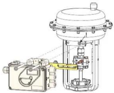
natural_image
Technical line drawing of a mechanical assembly with no visible text or symbols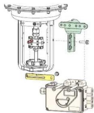
by Schneider Electric
1.2 MONTAŻ NA SIŁOWNIKACH OBROTOWYCH
natural_image
Technical line drawing of a mechanical testing setup with a box, base platform, and clamping device (no text or symbols)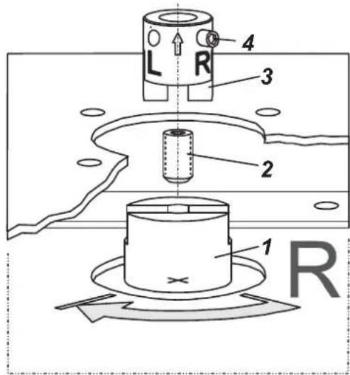
2 PRZYŁĄCZA PNEUMATYCZNE
Montaż bezpośredni

- SRI990 Analog Positioner
- Mounting to actuators
- Mounting to linear actuators
- Feedback lever for linear actuators:
- Carrier bolt B:
- Mounting to rotary actuators
- Pneumatic connections
- Electrical connections
- Limit switch
- SRI990-xxxT or U
- SRI990-xxxV
- START UP (setting by means of local switches and potentiometers)
- Initial setting
- Configuration direction of rotation of feedback shaft
- Setting of zero, span and gain
- Setting and Start Up of position transmitter 4-20mA
- Adjusting the start of the measuring range (4mA)
- Adjusting the end of the measuring range (20mA)
- Montage an Linearantriebe
- SRI990 Analogni pozicioner
- MONTIRANJE NA AKTUATORE
- MONTIRANJE NA LINEARNE AKTUATORE
- Poluga povratne sprege za linearne aktuatore:
- MONTIRANJE NA ROTACIONE AKTUATORE
- PNEUMATSKI PRIKLJUČCI
- MONTAŻ NA SIŁOWNIKACH LINIOWYCH
- MONTAŻ NA SIŁOWNIKACH OBROTOWYCH
- PRZYŁĄCZA PNEUMATYCZNE
Brand : SCHNEIDER
Model : SRI990
Category : Industrial measuring instrument