USER MANUAL RB100 VirtuFit
STEP 2
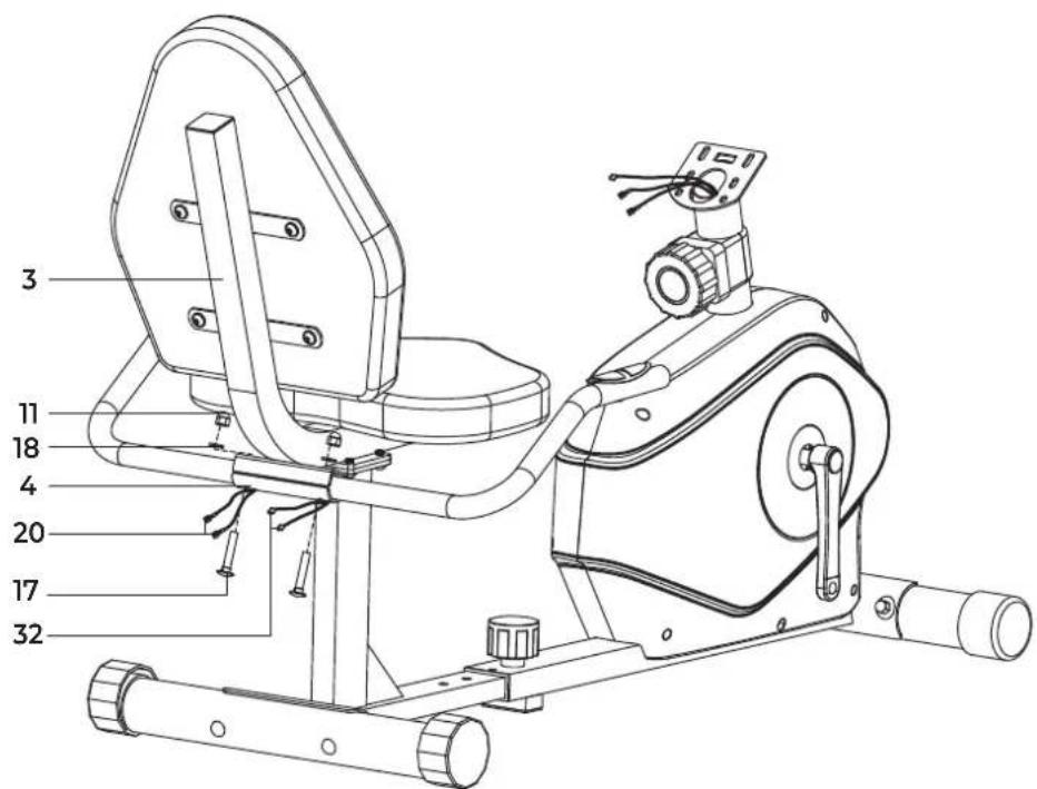
STEP 3
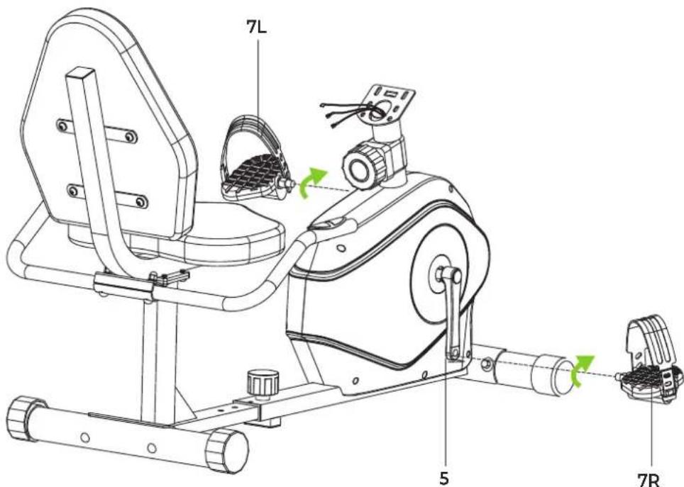
STEP 4
STEP 5
STEP 6
STEP 7
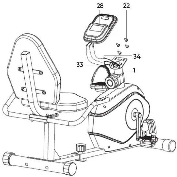
FIG. A

natural_image
Pure graphical interface element with three directional buttons (wheel, bidirectional arrow, gear) and a blank screen area, no text or symbols present.
INDEX
| Safety instructions | 08 |
| Guarantee | 08 | | |
| Assembly instructions 08 | |
| Training with heart rate 08 | |
| Maintenance | 09 | | |
| Cleaning | | 09 | |
| Battery | | 09 | |
| Troubleshooting | | 09 | |
| Console overview | | | 10 |
| Training guidelines | | | 11 |
| Replacement parts | | | 11 |
| Additional information 11 | |
| Declaration of the manufacturer 11 | |
SAFETY INSTRUCTIONS
WARNING!
Consult your doctor before you start exercising. This is particularly important for people with health problems. Please read all instructions before using the equipment. VirtuFit assumes no responsibility for injury or property damage resulting from the use of this equipment. Please read this manual carefully before assembling and/or using the equipment.
- Ensure the equipment is fully assembled and that all nuts and bolts are securely tightened before use.
• Lubricate all moving parts once a year using silicone spray.
- Avoid wearing loose clothing to prevent it from getting caught in moving parts.
- Place and use the equipment on a stable, level surface.
• Always wear clean sport shoes while using the equipment.
- Keep children and pets at a safe distance during use.
- Maintain proper balance at all times while operating this equipment.
- Do not insert fingers or other objects into any moving parts.
- Consult your physician before beginning any exercise program to determine the appropriate frequency, duration, and intensity based on your age and physical condition. Discontinue use immediately if you experience nausea, dizziness, fainting, headache, chest pain, tightness, or any other discomfort.
-
Do not move the equipment by holding it by the seat.
• The equipment is intended for use by one person at a time only.
-
This equipment is designed for home use only and supports a maximum user weight of 120 kg.
- Allow 1–2 meters of clearance behind the equipment to prevent accidents.
- Place the equipment on a clean, flat surface. Do not use it on thick carpets, as this can obstruct proper ventilation. Avoid placing this equipment outdoors or near water.
- Keep the storage area clean, dry, and level to prevent damage to the equipment.
• Use this equipment exclusively for its intended purpose.
- Operate the equipment only in environments with an ambient temperature between 0^ and 40^ . Store the equipment in environments with a temperature between -10^ and 60^ .
GUARANTEE
Warranty claims are excluded if the cause of the defect is the result of:
- Maintenance and repair work not carried out by an official dealer.
- Improper use, negligence and/or poor maintenance.
- Failure to maintain the appliance in accordance with the manufacturer's instructions.
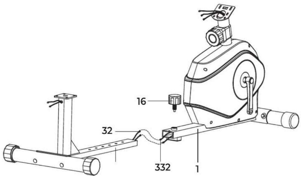
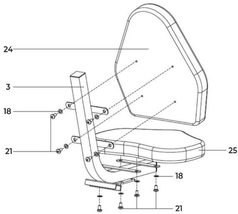
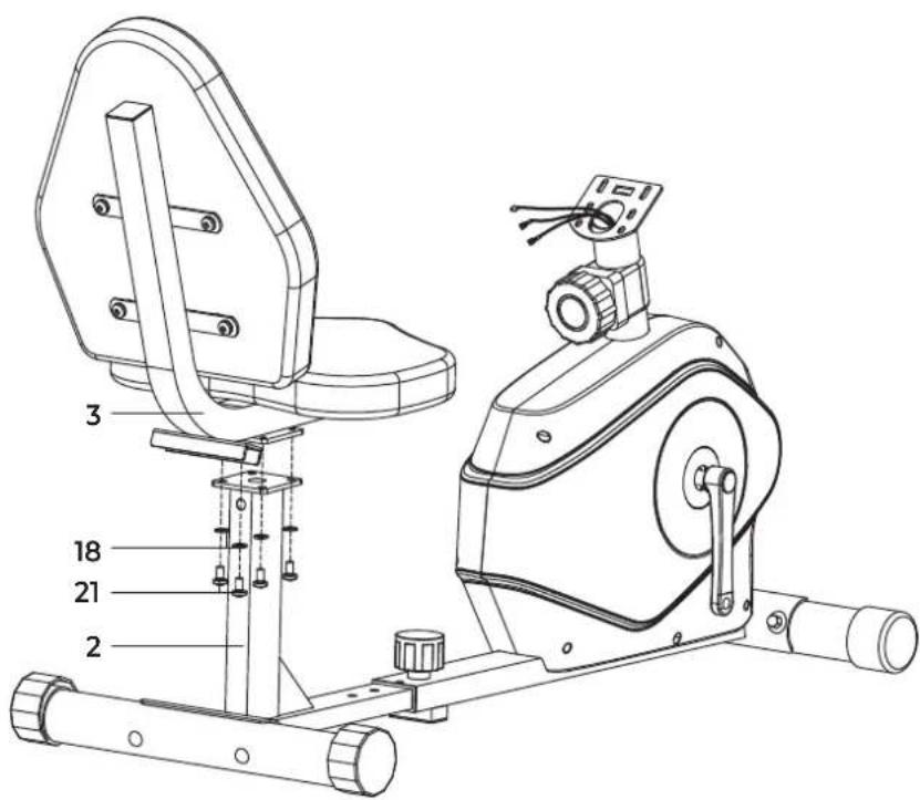
ASSEMBLY INSTRUCTIONS (STEP 1-7)
Missing parts: If any parts are missing from the packaging, carefully check the polystyrene foam and the appliance itself. Some parts (bolts, screws, etc.) are already attached to the unit.
Error message: Make sure that all cables are carefully attached. The brackets of the console are very sensitive and must be kept straight. If the console gives an error message after the equipment has been mounted, the brackets of the console may be bent. Straightening this aluminum part may make the error message disappear.
Hex head bolts: Make sure that the hex head spanner is pushed into the bolt before applying force. This will prevent the head of the socket bolt from turning.
TRAINING WITH HEART RATE
Hand sensors
This VirtuFit fitness equipment is equipped with hand sensors located on the handles for heart rate monitoring. The sensors function only when both are held simultaneously and continuously for an extended period. For accurate readings, your hands should be slightly moist and
apply consistent pressure to the sensors. Excessively dry or sweaty hands may result in inaccurate or irregular measurements.
MAINTENANCE
Safe and effective use of this appliance is only possible when it is correctly installed and properly maintained. It is your responsibility to ensure the appliance is serviced regularly. Any worn or damaged parts must be replaced before resuming use. This equipment is intended for indoor use and storage only. Prolonged exposure to outdoor conditions or fluctuations in temperature and humidity may severely affect the electrical components and moving parts. Always disconnect the power cord before cleaning or performing any maintenance.
Daily maintenance
- Wipe down the unit after each use to remove sweat and moisture.
- Ensure the equipment is free from dust and dirt.
- Avoid using harsh cleaning agents and keep the equipment away from excessive moisture.
Semi-annual maintenance
- Inspect all bolts and nuts connected to moving parts. Tighten them if necessary.
- Check the movement of all mobile parts and components. Apply silicone spray if needed.
General cleaning recommendations
- Clean the unit after each training session.
- Use a dry cloth to clean the control panel.
- Use a soft, clean cloth with mild detergent to remove persistent stains and dirt.
- Store the equipment in a clean, dry environment, away from direct heat and water sources.
CAUTION! Repairs must be performed by a qualified technician, unless otherwise instructed by the supplier or manufacturer.
CLEANING
Regular cleaning significantly extends the lifespan of your equipment. Keep the appliance free from dust by cleaning it frequently.
Preventative maintenance not only prolongs the life of the equipment but also helps avoid potential injuries.
For more detailed information, visit: www.virtufit.nl/service/faq
BATTERY
AAA BATTERIES
The display uses AAA batteries, which are replaceable on the back of the display. The batteries must be inserted correctly.
If the screen is unreadable or only parts of the image work, proceed as follows:
- Remove the batteries and wait 15 seconds.
- Replace the batteries correctly.
- Do not recharge, disassemble, or dispose batteries in a fire.
- Ensure correct polarity (+ and -) when inserting the batteries.
- Always replace all batteries at the same time; do not mix old and new batteries.
- Use alkaline batteries for optimal performance and longer life.
- Replace the batteries when the display dims or becomes unresponsive.
Battery replacement
- If the display shows inaccurate readings, battery replacement is recommended.
- This device requires 2 × AAA batteries.
TROUBLESHOOTING
PROBLEM SOLUTION
| The display does not show any values | Check that all sensor and console cables are securely connected and undamaged. |
| If the problem persists, gently adjust the position of the sensor. |
| Squeaking noise from the exercise bike | Ensure that all bolts and nuts are properly tightened. |
| Lubricate moving parts if necessary. |
| Ticking noise while pedaling | This may be caused by incorrectly mounted pedals. |
| Firmly tighten the pedal(s). |
| If the noise continues, remove and remount the pedals correctly:• The R (right) pedal must be mounted clockwise.• The L (left) pedal must be mounted counter-clockwise. |
| If the problem persists, contact your supplier. |
| Hand sensors are not functioning properly | Wash and dry your hands thoroughly, then try again. |
| Check the handlebar cables for damage and ensure they are properly connected to the connector. |
| If the problem persists, contact your supplier. |
| Console is not responding | Replace batteries. |
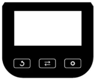
CONSOLE OVERVIEW (FIG. A)
natural_image
Simple black-and-white icon of a device control panel with three buttons (hook, rotate, rotate) and no text or symbols.

MODE
- Press to scroll through and select the desired display functions.
- Press and hold to reset all values to zero.

SET
- Use this button to manually set target values for Time, Distance, Pulse, and Calories
- Only when not in scan mode.

RESET
- Press once to reset the current Time, Distance, and Calories values to zero.
- Press and hold to reset all stored data completely.
Functions
SCAN
- Press the button until "SCAN" appears.
- The console will automatically cycle through the five functions: Time, Speed, Distance, Calories, and Pulse.
• Each value is displayed for 5 seconds before switching to the next.
TIME
- Displays the total exercise time from start to finish.
- Press ← until "TIME" appears, then press 🔍 to input a target time.
- When the countdown reaches zero, the computer will emit a 10-second signal.
SPEED
• Displays your current exercise speed.
DISTANCE
- Displays the total distance covered during the session.
- Press ← until "DIST" appears, then press 🔍 to input a target distance.
- When the countdown reaches zero, the computer will emit a 10-second signal.
CALORIES
• Displays the total calories burned during the session.
- Press until "CAL" appears, then press to input a target calorie amount.
- When the countdown reaches zero, the computer will emit a 10-second signal.
PULSE
- Press until "PULSE" appears.
- To measure your heart rate, place both hands firmly on the hand sensor contact pads.
- After 6–7 seconds, your heart rate (in beats per minute, BPM) will appear on the display.
NOTE! Initial readings may be temporarily elevated due to signal interference. After 2–3 seconds, the measurement should stabilize. This reading is intended for fitness reference only and is not suitable for medical use.
ALARM SOUND
- The computer emits a sound when any of the buttons are pressed.
AUTO ON/OFF & AUTO START/STOP
- If no activity is detected for 4 minutes, the display will shut off automatically to save power.
- The display will automatically turn on when the pedals start moving or when any button is pressed.
Console specifications
| Function | Auto scan Every 5 seconds | |
| Time 00:00 - 99:59 | |
| Speed 0.0 - 999.9 km/h | |
| Distance 0.00 - 999.9 km | |
| Calories 0.0 - 9999 Kcal | |
| Pulse rate 40 - 240 BPM | |
| Battery type | 2 x AAA |
| Operating temperature | 0°C - 40°C |
| Storage temperature | -10°C - 60°C |
Technical data
| Parameter | Value |
| Length | 140 cm |
| Width | 60 cm |
| Height | 83 cm |
| Weight | 25 kg |
| Max. user weight | 120 kg |
TRAINING GUIDELINES
A successful training program includes a warm-up, the actual training and a cool-down. Perform the complete training program at least twice, but preferably three times a week and keep a rest day between training sessions. After a few months, the intensity of the training can be increased, for example to four or five times a week.
The warm-up
The purpose of a warm-up is to prepare the body for training and to reduce the risk of injury. Warm up your body for two to five minutes before starting a cardio or strength training session. Do exercises that increase the heart rate and warm up the working muscles. Examples of this type of activity are running, jogging, jumping jacks, skipping and running in place.
Stretching
Stretching while the muscles are warm is very important after a good warm-up and cool-down. It reduces the risk of injury. Stretching exercises should be held for 15-30 seconds.
Cooling down
The purpose of the cool-down is to return the body to its (near) normal resting position at the end of the workout. A good cool-down slowly reduces your heart rate and promotes recovery.
REPLACEMENT PARTS
To request replacement parts for your VirtuFit equipment, please refer to the information on the front cover of this manual. In order to assist you efficiently, we kindly ask that you provide the following details when contacting our support team:
• The model number and serial number of the product
• The product name
- The part number and a clear description of the required part(s) (as listed in the parts list and shown in the exploded view section of this manual)
Providing accurate information will help us process your request quickly and effectively.
Responsible disposal of packaging
At VirtuFit, we are committed to reducing environmental impact. We kindly ask that you recycle all packaging materials through designated recycling facilities, in line with national waste reduction initiatives.
Product disposal
Your VirtuFit equipment is built to deliver long-term performance and reliability. When the time eventually comes to retire the product, please ensure it is disposed of in accordance with the European WEEE Directive. This means taking the product to an authorized collection point for safe and environmentally responsible recycling.
DECLARATION OF THE MANUFACTURER
VirtuFit hereby declares that this product complies with the following standards and directives:
· EN ISO 20957
• EMC (2014/30/EU)
• RoHS (2011/65/EU + 2015/863)
As a result, the product is CE-certified.
VirtuFit
natural_image
Black rectangular icon with three control buttons: clockwise, bidirectional arrow, and refresh button (no text or symbols)

MODE
Console Specifications
natural_image
Pure electrical control panel icon without any text or symbols
INSTRUCTIONS D'ASSEMBLAGE (FIG. 1-7)
natural_image
Pure electrical circuit lines without any symbols
Boutons de la console

MODE
natural_image
Black rectangular icon with a blank screen and three control buttons (hook, rotate, rotate) on the right side (no text or symbols)
Przyciski konsoli

MODE
natural_image
Simple black-and-white icon of a device control panel with three buttons (hook, bidirectional arrow, stop) and no text or symbols.
Tlačítka konzoly

REŽIM
natural_image
Black rectangular device with three control buttons: clockwise, bidirectional arrow, and stop button (no text or symbols)
natural_image
Pure electrical circuit lines without any symbols
Konzol gombok

MODE
natural_image
Black and white icon of a device control panel with three buttons (hook, rotate, refresh) and a blank screen area (no text or symbols)
natural_image
Pure graphical icon of a device control panel with three buttons (hook, rotate, refresh) and no text or symbols
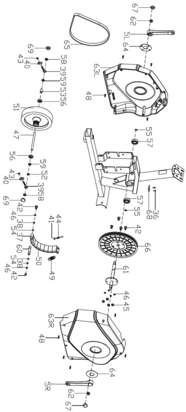
| # SKU DESCRIPTION QTY. |
| 1 VFSP000325 Front main frame 1 | | |
| 2 VFSP000326 Rear main frame 1 | | |
| 3 VFSP000327 Seat frame 1 | | |
| 6 VFSP000328 Rear bottom tube 1 | | |
| 5L | VFSP000193 | Crank (L) | 1 |
| 5R | VFSP000192 | Crank (R) | 1 |
| 7L | VFSP000190 Pedal (L) | 1 |
| 7R | VFSP000191 | Pedal (R) | 1 |
| 8 VFSP000329 Front bottom tube | 1 | |
| 9 VFSP000330 Carriage bolt M8*74 | 4 | |
| 10 | VFSP000331 | Arc washer D8.5*D25*2 | 4 |
| 11 VFSP000332 Acorn nut M8 | 6 | |
| 12 | VFSP000333 Rear end cap | 2 |
| 13 | VFSP000334 Front end cap | 2 |
| 14 | VFSP000335 Square end cap | 1 |
| 15 | VFSP000336 Plastic Bushing | 1 |
| 16 | VFSP000337 Pop-pin knob | 1 |
| 17 | VFSP000338 Carriage bolt M8*45 | 2 |
| 18 | VFSP000208 | Flat washer 08×013×1.5 | 14 |
| 21 | VFSP000200 | Allen bolt M8x16 12 | |
| 22 | VFSP000205 Screw console | 4 |
| 23 | VFSP000339 Square end cap | 2 |
| 24 | VFSP000340 | Backrest | 1 |
| 25 | VFSP000341 | Seat | 1 |
| 26+35+4+20+19 | VFSP000323 | Armrest set | 2 |
| 27 | VFSP000342 Tension controller | 1 |
| 28 | VFSP000189 Console | 1 |
| 29+30+31 | VFSP000181 | Tension controller cover | 1 |
| 32 | VFSP000343 Extension Pulse wire | 2 |
| 33 | VFSP000344 | Extension Pulse wire | 2 |
| 34 | VFSP000345 Sensor wire | 1 |
| 36 | VFSP000217 | Screw ST3*10 | 4 |
| 37 | VFSP000346 Magnetic board | 1 |
| 38 | VFSP000243 | Flat washer 06.2*110*1 | 2 |
| 39 VFSP000347 Adjustable bolt 2 | | | |
| 40 VFSP000348 U-shape washer 2 | | | |
| 41 VFSP000246 Hex bolt M5*60 1 | | | |
| 42 VFSP000247 Hex bolt M6*15 6 | | | |
| 43 | VFSP000244 Hex nut M6*H4 | | 2 |
| 44 VFSP000248 Hex nut M5*H4 | | 2 | |
| 45 | VFSP000220 Nylon nut M6*H6 | | 4 |
| 46 | VFSP000218 | Spring washer D6 | |
| 47 VFSP000349 Flywheel axle | | 1 | |
| 48 | VFSP000350 | Crossing tapping screw ST4.2*18 | |
| 49 VFSP000351 Spring | | 1 | |
| 50 VFSP000222 Magnet | | 8 | |
| 51 | VFSP000324 Flywheel-4kg set | | 1 |
| 52 | VFSP000294 | Spacer 010.5*116*3 | |
| 53 | VFSP000245 | Spacer 010*014*22 | |
| 54 VFSP000226 Snap ring D12 | | 2 | |
| 55 | VFSP000227 Snap ring D17 | | 2 |
| 56 VFSP000228 Bearing 6000Z | | 2 | |
| 57 | VFSP000229 Bearing 6203RZ | | 2 |
| 58 VFSP000230 Hex thin nut M10*1*H5 | | 2 | |
| 59 | VFSP000231 | Thin nut M10*1*5 | |
| 60 VFSP000352 Magnetic board axle | | 1 | |
| 61 | VFSP000353 Middle axle | | 1 |
| 62 VFSP000234 Flange nut M10*1.25*H8.5 | | 2 | |
| 63L | VFSP000354 Chain cover (L) | | 1 |
| 63R | VFSP000355 Chain cover (R) | | 1 |
| 64 | VFSP000356 Crank cover | | 2 |
| 65 | VFSP000357 Belt | | 1 |
| 66 VFSP000239 Belt pulley | | 1 | |
| 67 VFSP000358 Seal | | 2 | |
| 68 VFSP000359 Sensor | | 1 | |
| 69 VFSP000251 Cap S17 | | 2 | |
| 70 | VFSP000360 Hardware kit | | 1 |
virtufit