
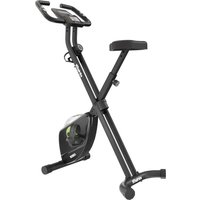
Etappe 2.0i - Indoor bike trainer VirtuFit - Free user manual and instructions
Find the device manual for free Etappe 2.0i VirtuFit in PDF.

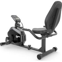
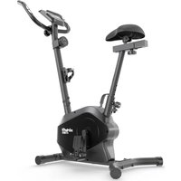
| Product Type | Indoor Exercise Bike |
| Brand | VirtuFit |
| Model | Etappe 2.0i |
| Maximum user weight | 130 kg |
| Power supply | Mains (power cable) |
| Display | LCD screen with time, distance, speed, RPM, calories, pulse, watt, average speed |
| Resistance levels | 24 levels (forward speed 1-3, backward 1-8) |
| Training programs | P1 (climb), P2 (mountain), P3 (highway), P4 (interval), P5 (relaxation), P6 (circuit), U1-U4 (user) |
| Heart rate measurement | Manual sensors on handlebars and wireless receiver (5 kHz) |
| Additional functions | Body fat test (BMI, FAT%, BMR), recovery test (Recovery), HRC program |
| Emergency brake | Yes |
| Transport wheels | Yes (on front stabilizer) |
| Pedals | With safety straps; right pedal (R) screwed clockwise, left (L) counterclockwise |
| Adjustments | Handlebar (height), saddle (height and horizontal position) |
| Adjustable feet | Yes (to compensate for uneven floors) |
| App compatibility | FitShow, Zwift (via QR code) |
| Operating temperature | 10 °C to 35 °C |
| Storage temperature | 5 °C to 45 °C |
| Daily maintenance | Clean sweat after each use; dust regularly |
| Semi-annual maintenance | Check and tighten all bolts and nuts; lubricate brake pad if necessary |
| Warranty | Excludes damage due to improper maintenance, inappropriate use, or unauthorized repairs |
| Error codes | E1 (motor or cable), E2 (manual sensor not held in time) |
| Spare parts | Contact the supplier |
Frequently Asked Questions - Etappe 2.0i VirtuFit
User questions about Etappe 2.0i VirtuFit
0 question about this device. Answer the ones you know or ask your own.
Ask a new question about this device
Download the instructions for your Indoor bike trainer in PDF format for free! Find your manual Etappe 2.0i - VirtuFit and take your electronic device back in hand. On this page are published all the documents necessary for the use of your device. Etappe 2.0i by VirtuFit.
USER MANUAL Etappe 2.0i VirtuFit
natural_image
Technical line drawing of a stationary exercise bike with wheels and support frame (no text or symbols)28 MAIN FRAME
STEP 2
11 14
M10x30 - 2 PCS
107 M8x20
STEP 3
3 M5x35 - 2PCS
STEP 01
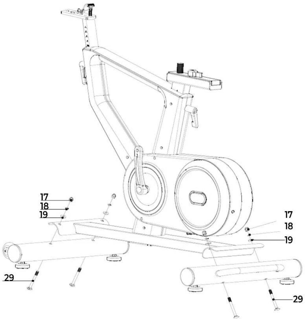
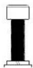
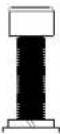
NOTE! Before attaching the front and rear stabiliser, remove the steel tube and fixing parts from the main frame. Make sure the transport wheels of the front stabiliser point forward.
NOTE! First attach the steering post (7) and then the handlebars (10). Make sure the direction of the handlebar (10) is correct.
natural_image
Line drawing of a person bending forward with hands raised (no text or symbols)1
natural_image
Line drawing of a person sitting cross-legged, holding their head in thought (no text or symbols)2
natural_image
Line drawing of a person performing a seated stretch or exercise (no text or symbols)3
natural_image
Line drawing of a person in athletic attire performing a forward bend gesture (no text or symbols)4
natural_image
Line drawing of a person performing a stretching exercise with arms raised (no text or symbols)5
INDEX
| Safety instructions | 11 | ||
| Guarantee | 11 | ||
| Assembly instructions 11 | |||
| Adjusting | 12 | ||
| Moving | 13 | ||
| Training with heart rate 13 | |||
| Training with fitness applications 13 | |||
| Maintenance | 14 | ||
| Troubleshooting | 14 | ||
| Error codes | 15 | ||
| Console | 15 | ||
| Programs | 15 | ||
| Training guidelines | 17 | ||
SAFETY INSTRUCTIONS

WARNING!
Consult your doctor before you start exercising. This is particularly important for people with health problems. Please read all instructions before using the machine. VirtuFit assumes no responsibility for injury or property damage resulting from the use of this equipment. Please read this manual carefully before assembling and/or using the machine.
- Make sure that the machine is properly assembled and that all nuts and bolts are tight before using it.
- Do not wear loose clothing to avoid getting caught in moving parts.
• Install and use the unit on a solid, level surface.
• Always wear clean sports shoes when using the appliance. - Keep children and pets away from the appliance when in use.
- Maintain your balance when using the device.
- Do not place your fingers or other objects in the moving parts.
- Before exercising, consult your physician to determine the appropriate frequency, duration and intensity of exercise for your age and physical condition. Stop exercising immediately if you experience nausea, shortness of breath, fainting, headache, chest pain, tightness or any other discomfort.
• Do not hold the machine by the seat when moving.
• This machine should only be used by one person at a time.
- This machine is designed for domestic use and the maximum user weight is 130 kg.
- Leave 1-2 metres of space behind the machine to avoid accidents.
- Place the machine on a clean, flat surface. Do not place it on a thick carpet, as this may hinder the ventilation of the machine. Do not place the machine outdoors or near water.
- Keep the storage area dry, clean and level to prevent damage. Do not use the device for any purpose other than training.
- Use the device only in an environment where the ambient temperature is between 10^ and 35^ . Store the device only in an environment where the temperature is between 5^ and 45^ .
GUARANTEE
Warranty claims are excluded if the cause of the defect is the result of:
- Maintenance and repair work not carried out by an official dealer. Unless otherwise specified by the supplier or manufacturer.
- Improper use, negligence and/or poor maintenance.
- Failure to maintain the appliance in accordance with the manufacturer's instructions.
ASSEMBLY INSTRUCTIONS (STEP 01-05)
Missing parts: If any parts are missing from the packaging, carefully check the polystyrene foam and the appliance itself. Some parts (bolts, screws, etc.) are already attached to the unit.
Error message: Make sure that all cables are carefully attached. The aluminium feet of the console are very sensitive and must be kept straight. If the console gives an error message after the machine has been mounted, the aluminium feet of the console may be bent. Straightening the aluminium feet may make the error message disappear.
Hex head bolts: Make sure that the hex head spanner is pushed into
the bolt before applying force. This will prevent the head of the socket bolt from turning.
ADJUSTING
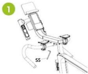
Adjusting the elbow pads (1)
- Unlock the bolts of the elbow pads with the hexagonal key S5.
- Adjust the elbow pads to a comfortable position.
- Retighten the bolts.
natural_image
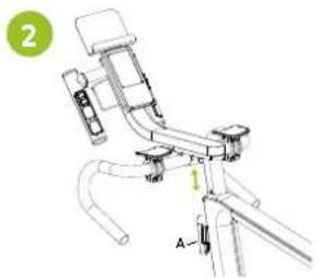
Technical line drawing of a bicycle with labeled component 'S5' and green circle marker (no text or symbols beyond labels)Adjusting the handlebars (2)
Before exercising, adjust the handlebar and saddle position to the height and distance that best suits the user.
Follow the steps below to adjust the handlebars FIG (2):
- Turn the adjustment knob (A) on the front of the main frame counter-clockwise.
- The handlebar is released and can be adjusted to the correct height.
- Tighten the round adjustment knob by turning it clockwise.
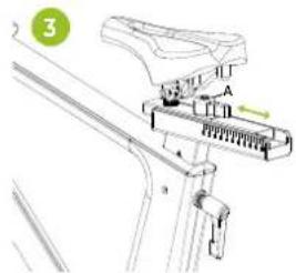
Adjusting the saddle (3-4)
Before riding, adjust the position of the handlebars and saddle to the height and distance that best suits the user.
Follow the steps below to adjust the horizontal position of the saddle (FIG. 3):
- Turn the adjustment knob on the underside of the saddle counter-clockwise (anti-clockwise).
- The saddle comes off and can be adjusted to a horizontal position to adjust the distance between the saddle and the handlebars.
- Tighten the adjustment knob by turning it clockwise
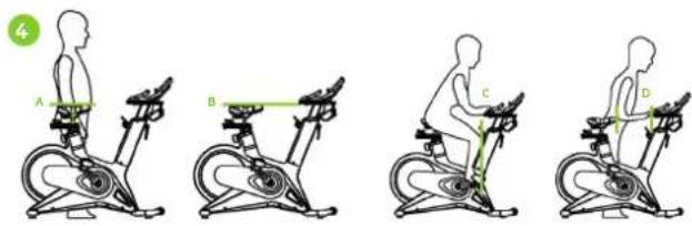
Follow the steps below to adjust the seat height (FIG. 4):
- Stand next to the machine and adjust the seat to hip height (FIG. 4A).
- The height of the saddle and handlebars should be the same (FIG. 4B). If not, adjust the handlebar height to match the saddle height.
- Make sure your knee is just behind your foot when your foot is towards the front of the machine (FIG. 4C).
- Adjust the handlebars so that the distance between the saddle and the handlebars is equal to the length of your forearm (FIG. 4D).
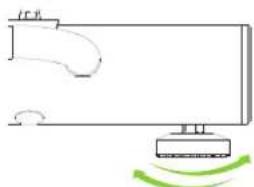
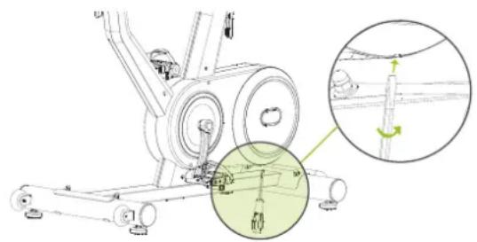
Leveling
Make sure that the bike is always on a stable surface. If in doubt, a rubber mat can be placed underneath the exercise bike to ensure a better grip on the floor. The bike can be adjusted by turning the adjustable feet on either side of the bike (FIG. A). This allows the bike to compensate for unevenness in the floor.
natural_image
Simple line drawing of a mechanical or electrical component with a base and a curved arrow, no text or symbols present.Safety straps
- Get on the bike.
-
Put your foot on the pedal and tighten the belt.
-
Start pedalling.
- After pedalling, remember to press the safety button before unfastening the safety belt.
- You can now get off the bike safely.
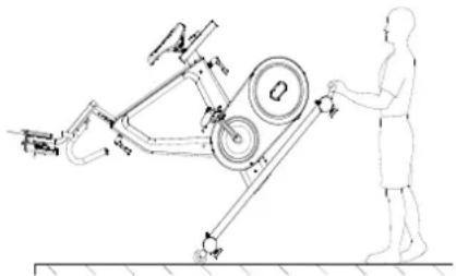
MOVING
CAUTION! Store the unit in a dry place out of reach of children. Make sure the unit is stable and secure to prevent it from falling on children or animals.
Push the handlebar down until the transport wheels of the front stabiliser touch the ground. When the transport wheels touch the ground, the bike can be easily moved to the desired location.
natural_image
Technical line drawing of a mechanical device with labeled components and a human figure interacting (no text or symbols present)TRAINING WITH HEART RATE
Hand sensors
This VirtuFit fitness machine is equipped with hand sensors for measuring heart rate. The hand sensors are attached to the handle and only work if both sensors are held for a longer period of time. For optimal performance, it is important that the hands are slightly moist and exert constant pressure on the sensors. Hands that are too dry or moist may cause abnormal readings.
NOTE! To avoid interference, never use the hand sensors with a wireless heart rate monitor.
Wireless heart rate receiver (5 kHz)
This VirtuFit fitness device is equipped with a wireless heart rate receiver. For the heart rate measurement with a wireless heart rate monitor, you use a heart rate monitor which works on a 5 kHz frequency. With a wireless heart rate monitor, it is important that the electrodes are slightly moist and the heart rate monitor fits well to your body. Refer to your heart rate monitor's user manual for proper instructions. Incorrect use of the heart rate monitor may result in abnormal readings.
NOTE!
- A wireless heart rate monitor is not included as standard. Contact your dealer to purchase a wireless heart rate monitor.
- To avoid interference, never use the wireless heart rate monitor in combination with the hand sensors.
WARNING!
· If you have a pacemaker, we recommend that you consult your physician before using a wireless heart rate monitor
- In rooms with multiple heart rate monitors, it is recommended that you keep enough distance to avoid interference between different devices.
· Always try to keep the wireless heart rate monitor within a range of 1 meter from the console for optimal reception.
· Always wear a wireless heart rate monitor directly on the body, under clothing.
TRAINING WITH FITNESS APPLICATIONS
VirtuFit does not provide service for third party fitness applications such as Kinomap, iConsole, FitShow etc. If you encounter problems with a third party fitness application, please contact the developer of the application in question.
Instruction
- To scan the QR code with an Android or IOS phone or tablet, a QR code scanner is required. The app for scanning QR codes can be downloaded from the App Store or Google Play Store.
- Scan one of the QR codes below to go directly to the App Store or Google Play Store page where the fitness app can be downloaded.
- Scan the QR code on the right to access the fitness app manual. The manual describes step by step how to connect the fitness app to the device, how the fitness app works and what its capabilities are.
Fitshow

APP STORE

GOOGLE PLAY

MANUAL
Zwift

APP STORE

GOOGLE PLAY

MANUAL
MAINTENANCE
Safe and efficient use can only be achieved if the appliance is properly installed and maintained. It is your responsibility to ensure that the appliance is maintained regularly. Parts that have been used and/or damaged must be replaced before the appliance is used again. The appliance should only be used and stored indoors. Long-term exposure to weather and temperature/humidity changes can have a serious impact on the electrical components and moving parts of the unit. Always unplug the power cord from the unit before cleaning or servicing it.
Daily maintenance
- Clean and remove sweat and moisture after each use.
- Check that the unit is free of dust and dirt.
- Do not use aggressive cleaning agents and keep the device away from moisture.
Semi-annual maintenance
- Inspect all bolts and nuts connected to the moving parts of the unit. Tighten bolts and nuts as necessary and appropriate.
We recommend the following:
- Clean the unit after use.
- Use a dry cloth to clean the control panel and the areas around the on/off switch.
- Use a soft, clean cloth and detergent to remove stubborn marks and dirt from the unit.
- Store the unit in a safe, dry place away from heat and water.
CAUTION! Repairs must be carried out by a professional technician, unless otherwise specified by the supplier or manufacturer.
Cleaning
General cleaning of the unit will extend its life. Keep the appliance clean by dusting it regularly. Regular maintenance will prolong the life of your appliance and prevent injuries! For more information, please visit https://www.virtufit.nl/service/faq/
CAUTION! Wear clean shoes to reduce the risk of soiling the machine. At least once a year, remove the cover to remove dust.
Opening the Chain Box
- Have a Phillips screwdriver and a flathead screwdriver ready.
- Locate the hole at the bottom of the chain case.
- Insert the flathead screwdriver into the hole.
- Pull the chain case open slightly while holding the handle of the flathead screwdriver.
- Remove the screws with the Phillips screwdriver.
natural_image
Mechanical assembly diagram showing a stationary bike with pulleys and a rotating shaft, plus an inset close-up of the mechanism (no text or symbols)TROUBLESHOOTING
The display does not show any values: Check that the sensor and console cables are properly attached and undamaged. If this does not solve the problem, contact the supplier.
Device squeaks: Check that all bolts and nuts are tight. If necessary. Check whether the brake pad needs to be lubricated.
Ticking noise when pedalling: This may be caused by one of the pedals. Remove the pedal(s) and mount it (them) correctly on the unit. Tighten the pedal(s) firmly. If this does not solve the problem, contact the supplier.
NOTE! The "R" (right) pedal must be mounted clockwise and the "L" (left) pedal must be mounted counter-clockwise.
Console does not work: If there is no signal when pedalling, check that the cable is correctly connected.
Heart rate display does not function:
- The sensor cables from the heart rate sensor to the display are not properly fitted or have become loose during use.
- The sensors may have become damp, dirty or greasy. Clean them regularly. If there is no signal when you pedalling check that the cable is properly attached.
ERROR CODES
E1:
- Motor does not work (motor problems)
Solution: Check that the motor wiring plug is connected correctly. Reconnect the plug. If this does not solve the problem, contact the supplier. - Broken cable in the machine
Solution: Check that the cables are not damaged or in danger of causing a short circuit. Replace the cable. If this does not solve the problem, contact the supplier. - The console does not give a signal to the motor
Solution: Replace the console. If this does not solve the problem, contact the supplier.
E2 :
• After starting the body fat test, the hand sensor is not held fast enough with the hand.
Solution: Hold the handheld sensor within 3 seconds of starting the test program. If this does not solve the problem, contact the supplier.
- The console does not display the heart rate value
Solution: Check if a heart rate value is displayed in another mode. If this does not solve the problem, contact the supplier.
CONSOLE (FIG. A)

-
-
- Press to select a programme or increase/decrease values.
-
-
Press to go to the main menu. Press and hold to reset all values.
-
Recovery - Heart rate Recovery test.
. ← Confirm the selected value. -
Start or stop training.
-
- FRONT Handlebar left. Increase or decrease front gear.
-
- REAR Handlebar right. Increase or decrease rear gear.
Functions
- RPM Revolutions per minute.
-
SPEED The current speed during exercise is displayed.
-
TIME The time measured from the start of the exercise is displayed. If a training time has been set, the time will be counted down.
- DISTANCE The distance covered during the exercise is displayed. displayed. If a distance is set, the distance will will be counted down.
- AVERAGE SPEED The average speed during the exercise.
- CALORIES The number of calories burned during the exercise is displayed. If a calorie target has been set, the number of calories will be counted down.
-
PULSE When using a chest strap, the heart rate will be displayed during exercise. If a target heart rate is set, an alarm will sound when the target heart rate is reached.
-
WATT Displays the wattage.
- GEAR 24 resistance levels.
- FRONT Front gear 1-3.
- REAR Rear gear 1-8.
PROGRAMS (FIG.B, 1-3)
Manual Program (FIG. B-1)
- Press - + to display the different programs. P1 climb mode, P2 mountain mode, P3 highway mode, P4 interval mode, P5 relaxation mode, P6 circuit mode.
- Press ▶ to start the workout or press ← to enter the set mode.
- In set mode, press to select the set value. The selected value (time, distance, calories, age) will flash (in P1-P5).
- Press - + to increase or decrease the value and press to select the next item.
- Press ▶ to start the workout.
- During the workout, the resistance is automatically adjusted according to the program you set. If you are not happy with this, you can press - +to increase or decrease the value.
- If one of the settings is made, the corresponding value is counted down. If this value is 0, a signal sounds.
- During exercise, press ▶stop or pause the machine.
Body Fat (FIG. B-2)
- Press ← to select the programme. The order of setting is: gender -> height -> weight -> age.
- Press to increase or decrease the value.
• M means male and F means female. - Press 10 seconds to start the test and the display will show BMI, FAT%. CAUTION! Press the heart rate sensor in continuous display before testing.
- The test should be performed when the body is relaxed and the heart rate is calm.
BMI (BODY MASS INDEX)
| GENDER/AGE | THIN | NORMAL | SLIGHTLY FAT | FAT | OBESE |
| MALE < 30 | < 14 | 14 ~ 20 | 20.1 ~ 25 | 25.1 ~ 35 | >35 |
| MALE >30 | < 17 | 17 ~ 23 | 23.1 ~ 28 | 28.1 ~ 38 | >38 |
| FEMALE <30 | < 17 | 17 ~ 24 | 24.1 ~ 30 | 30.1 ~ 40 | >40 |
| FEMALE >30 | < 20 | 20 ~ 27 | 27.1 ~ 33 | 33.1 ~ 43 | >43 |
BODY FAT (%)
| GENDER | LOW | MEDIUM | MEDIUM/ HIGH | HIGH |
| MALE | < 13 | 13 - 25.9 | 26 - 30 | >30 |
| FEMALE | < 23 | 23 - 35.9 | 36 - 40 | >40 |
B.M.R. (BASIC METABOLIC RATE)
The average number of calories burned per day for the basic needs of life.
• Referentie 1300 ± 100 (22 - 40 years).
BODY TYPE (COMPOSITE FIGURE)
| B1 | EXTREMELY THIN | B6 | ABOVE NORMAL |
| B2 | THIN | B7 | OVERWEIGHT |
| B3 | RELATIVELY THIN | B8 | OBESE |
| B4 | BELOW NORMAL | B9 | EXTREMELY OBESE |
| B5 | NORMAL | ||
HRC (FIG. B-3)
- Press ← to select the programme. The order of setting is:
time -> distance -> calories -> target heart rate.
- Press to increase or decrease the value.
- Press to start the workout. The resistance is automatically adjusted to the target heart rate.
- If one of the parameters is set, the corresponding value is counted down. When this value is 0, a beep will sound.
- During the workout, press to stop or pause the unit.
NOTE! For best use of the HRC function, it is recommended that you wear a wireless chest belt during exercise. If the display does not detect the heart rate value, the resistance will not change automatically.
User Program (FIG. B-4)
- Press to select the U1-U4 program.
- Press ▶ to start the workout or to enter the setting
mode. The order of setting is: time -> distance -> calories -> resistance.
- Press to increase or decrease the value or to move to the next point.
- Press to start the workout and during the workout press
- +to increase or decrease the resistance.
- When one of the parameters is set, the corresponding value is counted down. When this value is 0, a beep will sound.
- During the workout, press to stop or pause the workout.
Recovery (FIG. B-5)
- During a workout, press when the heart rate value is displayed and monitor the heart rate.
- TIME displays "0:60" and begins counting down from 60 seconds. The system will begin the test.
- When TIME is at "0:00", F1 - F6 is displayed on the screen. This indicates your heart rate recovery level.
| F1 = 1.0 | OPTIMUM |
| 1.0 < F2 < 2.0 | GOOD |
| 2.0 < F3 < 2.9 | RELATIVELY GOOD |
| 3.0 < F4 < 3.9 | NORMAL |
| 4.0 < F5 < 5.9 | RELATIVELY BAD |
| F6 = 6.0 | BAD |
NOTE! It is recommended that you perform the heart rate test within the aerobic heart rate range during training. This will not affect the test result.
Pulse
SEE ALSO CHAPTER "TRAINING WITH HEART RATE".
| AGE | TRAINING ZONEMIN-MAX (BPM) | AGE | TRAINING ZONEMIN-MAX (BPM) |
| 20 133 - 167 55 122 - 155 | |||
| 25 132 - 166 60 121 - 153 | |||
| 30 130 - 164 65 119 - 151 | |||
| 35 129 - 162 70 118 - 150 | |||
| 40 127 - 161 75 117 - 147 | |||
| 45 125 - 159 80 115 - 146 | |||
| 50 124 - 156 85 114 - 144 |
TRAINING GUIDELINES (FIG. C, 1-5)
A successful training program includes a warm-up, the actual training and a cool-down. Perform the complete training program at least twice, but preferably three times a week and keep a rest day between training sessions. After a few months, the intensity of the training can be increased, for example to four or five times a week.
The warm-up
The purpose of a warm-up is to prepare the body for training and to reduce the risk of injury. Warm up your body for two to five minutes before starting a cardio or strength training session. Do exercises that increase the heart rate and warm up the working muscles. Examples of this type of activity are running, jogging, jumping jacks, skipping and running in place.
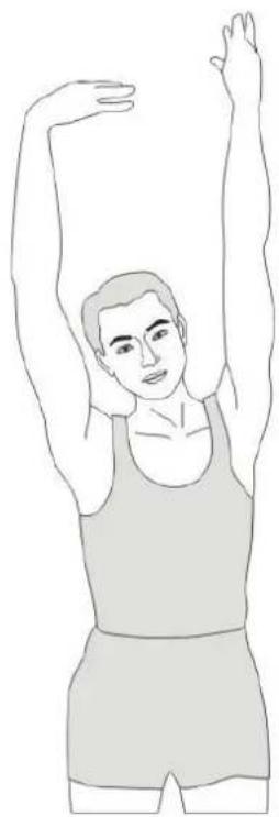
Stretching
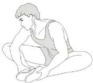
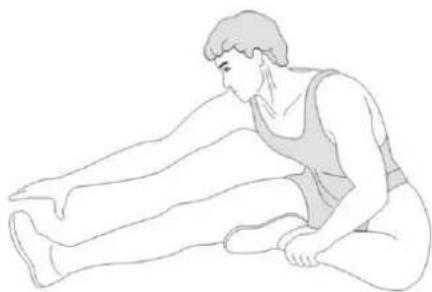
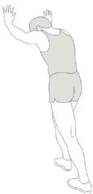
Stretching while the muscles are warm is very important after a good warm-up and cool-down. It reduces the risk of injury. Stretching exercises should be held for 15-30 seconds. Here are some examples of stretching exercises:
• Toe touch (Fig. C-1)
• Inner thight stretch (Fig. C-2)
• Hamstring stretch (Fig. C-3)
• Achilles stretch (Fig. C-4)
• Side stretch (Fig. C-5)
Cooling down
The purpose of the cool-down is to return the body to its (near) normal
resting position at the end of the workout. A good cool-down slowly reduces your heart rate and promotes recovery.
INHOUD
natural_image
Technical line drawing of a mechanical device with labeled component S5 (no text or symbols beyond label)Stuur afstellen (2)
natural_image
Mechanical assembly diagram showing a lever mechanism with labeled component A (no text or symbols present)Zadel afstellen (3-4)
natural_image
Simple line drawing of a monitor with a curved handle and a green circular motion indicator (no text or symbols)Veiligheidsriemen
natural_image
Technical line drawing of a stationary exercise machine with a person standing beside it (no text or symbols present)natural_image
Mechanical assembly diagram showing a rotating device with a highlighted circular component (no text or symbols)PROBLEEMOPLOSSINGEN
PROGRAMMA'S (FIG.B, 1-3)
Handmatig programma (FIG. B-1)
B.M.R. (BASALE METABOLISCHE SNELHEID)
| B1 | EXTREMELY THIN | B6 | ABOVE NORMAL |
| B2 | THIN | B7 | OVERWEIGHT |
| B3 | RELATIVELY THIN | B8 | OBESE |
| B4 | BELOW NORMAL | B9 | EXTREMELY OBESE |
| B5 | NORMAL | ||
HRC (FIG. B-3)
natural_image
Technical line drawing of a mechanical device with labeled component 'S5' and green circle marker (no readable text or symbols beyond label)natural_image
Technical line drawing of a mechanical device with labeled parts (no text or symbols present)natural_image
Simple line drawing of a device with a curved handle and a green motion arrow indicating rotation (no text or symbols)Sicherheitsgurte
natural_image
Technical line drawing of a mechanical device with a human figure observing it (no text or symbols present)natural_image
Mechanical assembly diagram showing a rotating device with a magnified inset view of the shaft (no text or labels)FEHLERSUCHE
PROGRAMME (FIG.B, 1-3)
Manuelles Programm (FIG. B-1)
| B1 | EXTREMELY THIN | B6 | ABOVE NORMAL |
| B2 | THIN | B7 | OVERWEIGHT |
| B3 | RELATIVELY THIN | B8 | OBESE |
| B4 | BELOW NORMAL | B9 | EXTREMELY OBESE |
| B5 | NORMAL |
HRC (FIG. B-3)
natural_image
Technical line drawing of a mechanical device with labeled part S5 (no text or symbols beyond label)natural_image
Technical line drawing of a mechanical device with labeled components (no text or symbols)natural_image
Simple line drawing of a device with a curved handle and a sensor emitting green motion arrows (no text or symbols)natural_image
Technical line drawing of a mechanical exercise setup with a person standing beside it (no text or symbols present)ENTRAÎNEMENT AVEC LA FRÉQUENCE CARDIAQUE
Capteurs de main
natural_image
Mechanical assembly diagram showing a rotating device with a magnified inset highlighting a component detail (no text or symbols present)DÉPANNAGE
PROGRAMMES (FIG.B, 1-3)
Programme manuel (FIG. B-1)
| B1 | EXTREMELY THIN | B6 | ABOVE NORMAL |
| B2 | THIN | B7 | OVERWEIGHT |
| B3 | RELATIVELY THIN | B8 | OBESE |
| B4 | BELOW NORMAL | B9 | EXTREMELY OBESE |
| B5 | NORMAL | ||
HRC (FIG. B-3)
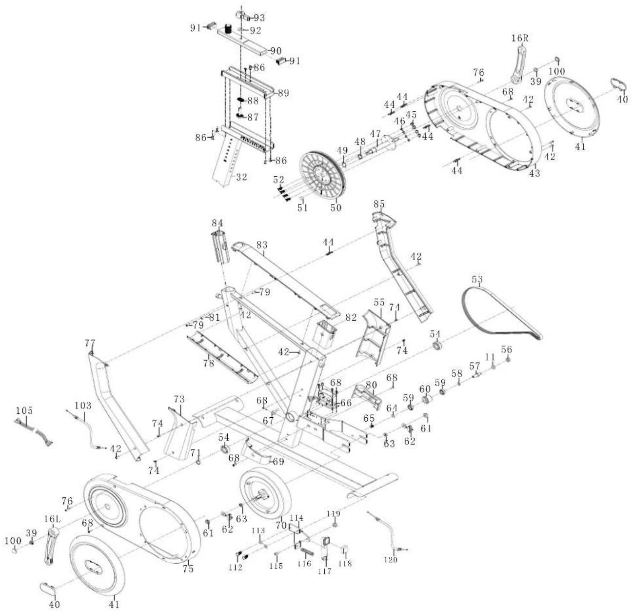
DESCRIPTION QTY.
| 1 | Display | 1 |
| 2 | Right handle top cover | 1 |
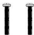
| 3 | Cross pan head screw M5*35 | 2 |
| 4 | Square end cap J50 | 1 |
| 5 | Right handle bottom cover | 1 |
| 6 | Left handle top cover | 1 |
| 7 | Display post | 1 |
| 8 | Left handle bottom cover | 1 |
| 9 | Cross recessed pan head tapping screwsST3*25*Φ5.6 | 6 |
| 10 | Handlebar | 1 |
| 11 | Washer d10*φ20*2.0 | 3 |
| 12 | Spring washer d10 | 2 |
| 13 | L-shaped knob | 2 |
| 14 | Hexagon socket head screw | 2 |
| 15 | Pedal | 1pair |
| 16 | Crank | 1pair |
| 17 | Cap nut | 4 |
| 18 | Washer d8 | 4 |
| 19 | Arc washer d8*Φ20*2*R38 | 4 |
| 20 | Inner hex pan head bolt Φ7.8*30*M6*15*S5 | 2 |
| 21 | Transportation wheel | 2 |
| 22 | Washer d6*Φ12*1.5 | 2 |
| 23 | Inner hex pan head bolt M6*12*S5 | 2 |
| 24 | Round end cap Φ76 | 4 |
| 25 | Front stabilizer | 1 |
| 26 | Nut M8*H5.5*S14 | 4 |
| 27 | Adjustable leveling knob | 4 |
| 28 | Mainframe | 1 |
| 29 | Square neck bolt M8*90*20*H5 | 4 |
| 30 | Rear stabilizer | 1 |
| 31 | No need | - |
| 32 | Saddle post | 1 |
| 33 | End cap D28 | 2 |
| 34 | Saddle | 1 |
| 35 | Handlebar post | 1 |
| 36 | Square end cap 1 | |
| 37 | IPAD holder | 1 |
| 38 | Round end cap | 4 |
DESCRIPTION QTY.
| 39 Flange nut M10*1.25*H7.5*S14 2 | ||
| 40 Decoration cover for plastic plate 2 | ||
| 41 Plastic plate 2 | ||
| 42 Cross pan head screw ST4.2*19*Φ8 7 | ||
| 43 Right chain cover 1 | ||
| 44 Connection bar 5 | ||
| 45 Nylon nut 8 | ||
| 46 Spring washer D6 4 | ||
| 47 Middle shaft | 1 | |
| 48 Middle shaft spacer | 1 | |
| 49 Corrugated washer d20*Φ26*0.3 | 1 | |
| 50 Belt wheel | 1 | |
| 51 Round magnet | 1 | |
| 52 Bolt M6*16*S10 | 4 | |
| 53 Multi-V belt | 1 | |
| 54 Bearing | 2 | |
| 55 Saddle post top right cover | 1 | |
| 56 Nylon nut M10*H9.5*S17 | 1 | |
| 57 Free wheel shaft | 1 | |
| 58 Corrugated washer d12*Φ15.5*0.3 | 1 | |
| 59 Bearing | 2 | |
| 60 Free wheel | 1 | |
| 61 Flange nut M10*1*H8*S15 | 2 | |
| 62 Adjustable chain bolt | 2 | |
| 63 Conical nut M10*1*H5*S17 | 2 | |
| 64 Washer d6*Φ16*1.5 1 | ||
| 65 Bolt M6*10*S10 | 1 | |
| 66 Motor | 1 | |
| 67 Sensor | 1 | |
| 68 Cross pan head screw ST4.2*16*Φ8 9 | ||
| 69 Saddle post bottom left cover | 1 | |
| 70 Flywheel | 1 | |
| 71 Snap ring d20 | 1 | |
| 72 No need | - | |
| 73 Saddle post top left cover | 1 | |
| 74 Cross pan head screw ST4.2*6*φ8 | 4 | |
| 75 Left chain cover | 1 | |
| 76 Cross pan head self-drilling screw ST4.2*25*Φ8 | 2 | |
DESCRIPTION QTY.
| 77 | Left handlebar post cover | 1 |
| 78 | Bottom cover 1 | |
| 79 | Cross pan head screw M5*10*φ10 | 2 |
| 80 | Saddle post bottom right cover | 1 |
| 81 | Limitation shaft | 1 |
| 82 | Bush | 1 |
| 83 | Top cover | 1 |
| 84 | D-shaped bush | 2 |
| 85 | Right handlebar post cover | 1 |
| 86 | Cross countersunk screwsM5*18*φ8 | 6 |
| 87 | Locking block | 1 |
| 88 | Rubber band | 1 |
| 89 | Bottom slider 1 | |
| 90 | Saddle seat | 1 |
| 91 | Square end cap J40 | 2 |
| 92 | Washer d10*φ20*2 | 1 |
| 93 | Locking knob | 1 |
| 94 | No need | - |
| 95 | No need | - |
| 96 | Elbow pads 2 | |
| 97 | Bolt M6*15*S5 | 4 |
| 98 | Support plate | 2 |
| 99 | Lock block for Elbow pads | 2 |
| 100 | Crank cover | 2 |
| 101 | Package tube | 2 |
| 102 | Adaptor | 1 |
| 103 | Resistance wire | 1 |
| 104 | Extension wire 1 | 1 |
| 105 | Extension wire 2 | 1 |
| 106 | Pulse wire 1 | |
| 107 | Hexagon socket countersunk head bolts | 2 |
| 108 | Aluminum bottle holder | 1 |
| 109 | Bolt M6*12*S5 | 1 |
| 110 | Brake handle | 1 |
| 111 | End cap F80*40 | 1 |
| 112 | Bolt M8*20*S13 | 2 |
| 113 | Washer d8*φ16*1.5 | 2 |
| 114 | Brake rod | 1 |
DESCRIPTION QTY.
| 115 Bolt M8*12*S5 1 | |
| 116 Spring 1 | |
| 117 Brake bolt 1 | |
| 118 Brake block 1 | |
| 119 Nylon nut M8*H7.5*S13 1 | |
| 120 Brake cable 1 | |
| A Allen wrench S8 1 | |
| B Multi-function wrench S13-14-15 1 | |
| C Allen wrench S5 1 |
virtufit
- STEP 2
- STEP 3
- STEP 01
- SAFETY INSTRUCTIONS
- WARNING!
- GUARANTEE
- ASSEMBLY INSTRUCTIONS (STEP 01-05)
- ADJUSTING
- Adjusting the elbow pads (1)
- Adjusting the handlebars (2)
- Follow the steps below to adjust the handlebars FIG (2):
- Adjusting the saddle (3-4)
- Follow the steps below to adjust the horizontal position of the saddle (FIG. 3):
- Follow the steps below to adjust the seat height (FIG. 4):
- Leveling
- Safety straps
- MOVING
- TRAINING WITH HEART RATE
- Hand sensors
- Wireless heart rate receiver (5 kHz)
- NOTE!
- TRAINING WITH FITNESS APPLICATIONS
- Instruction
- Fitshow
- MAINTENANCE
- Daily maintenance
- Semi-annual maintenance
- We recommend the following:
- Cleaning
- Opening the Chain Box
- TROUBLESHOOTING
- Heart rate display does not function:
- ERROR CODES
- E1:
- E2 :
- CONSOLE (FIG. A)
- Functions
- PROGRAMS (FIG.B, 1-3)
- Manual Program (FIG. B-1)
- Body Fat (FIG. B-2)
- B.M.R. (BASIC METABOLIC RATE)
- HRC (FIG. B-3)
- User Program (FIG. B-4)
- Recovery (FIG. B-5)
- Pulse
- TRAINING GUIDELINES (FIG. C, 1-5)
- The warm-up
- Stretching
- Cooling down
- INHOUD
- Stuur afstellen (2)
- Zadel afstellen (3-4)
- Veiligheidsriemen
- PROBLEEMOPLOSSINGEN
- PROGRAMMA'S (FIG.B, 1-3)
- Handmatig programma (FIG. B-1)
- B.M.R. (BASALE METABOLISCHE SNELHEID)
- Sicherheitsgurte
- FEHLERSUCHE
- PROGRAMME (FIG.B, 1-3)
- Manuelles Programm (FIG. B-1)
- ENTRAÎNEMENT AVEC LA FRÉQUENCE CARDIAQUE
- Capteurs de main
- DÉPANNAGE
- PROGRAMMES (FIG.B, 1-3)
- Programme manuel (FIG. B-1)
- DESCRIPTION QTY.
- virtufit
Brand : VirtuFit
Model : Etappe 2.0i
Category : Indoor bike trainer