
SC001G - Slicer MAKITA - Free user manual and instructions
Find the device manual for free SC001G MAKITA in PDF.

| Brand | Makita |
| Model | SC001G |
| Product type | Rebar Cutter (rebar cutting machine) |
| Maximum cutting capacity (diameter) | 16 mm |
| Capacity by grade | Grade 40 (490 N/mm²): 16 mm; Grade 60 (620 N/mm²): 16 mm |
| Cutting time | 1.7 seconds |
| Total length | 321 mm |
| Net weight | 6.0 kg - 6.3 kg (depending on battery) |
| Rated voltage | 36 V - 40 V DC max. |
| Compatible battery type | Makita BL4025 / BL4040 (Lithium-ion 36 V) |
| Compatible charger | Makita DC40RA |
| Sound pressure level (LpA) | 81.6 dB(A) |
| Sound power level (L_WA) | 89.6 dB(A) |
| Noise uncertainty | 3 dB(A) |
| Vibrations (rebar cutting) | 9.593 m/s² |
| Vibration uncertainty | 1.5 m/s² |
| Motor rotation | 360 degrees |
| Recommended hydraulic oil type | Hydraulic oil ISO 46 (Makita, Super Hyrando #46, Shell Tellus plus #46) |
| Tool protection | Overload, overheating, deep battery discharge |
| Country of manufacture | Not specified (subject to change) |
| Warranty | Manufacturer's warranty (consult Makita) |
| Included accessories | Hex wrench, instruction manual |
Frequently Asked Questions - SC001G MAKITA
User questions about SC001G MAKITA
0 question about this device. Answer the ones you know or ask your own.
Ask a new question about this device
Download the instructions for your Slicer in PDF format for free! Find your manual SC001G - MAKITA and take your electronic device back in hand. On this page are published all the documents necessary for the use of your device. SC001G by MAKITA.
USER MANUAL SC001G MAKITA
natural_image
Technical line drawing of a handheld power tool with attached circuit board (no text or symbols)
natural_image
Technical line drawing of a mechanical clamp or bracket assembly (no text or symbols)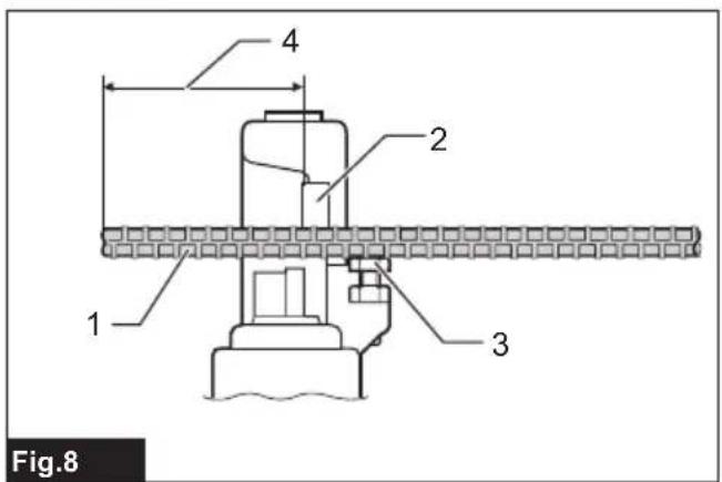

natural_image
Illustration of a hand using a tool to measure a brick wall component (no text or symbols present)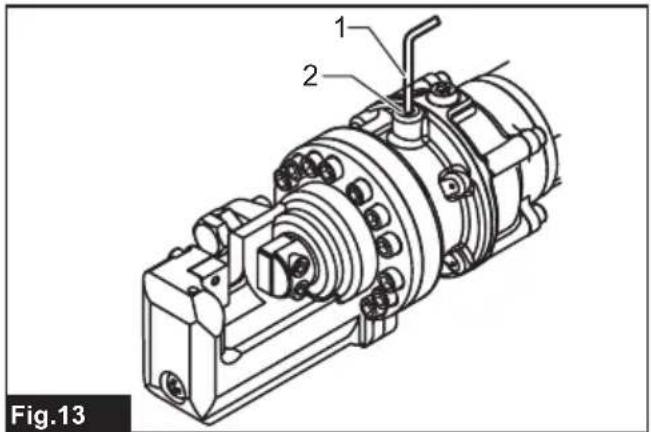
natural_image
Technical line drawing of a mechanical assembly with labeled component 1, no readable text or symbols beyond label and figure marker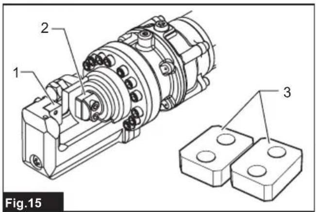
natural_image
Technical line drawing of a mechanical assembly with no visible text or symbolsSPECIFICATIONS
| Model: SC001G | |
| Max. Cutting Capacity (Dia.mm) 16 mm | |
| Grade 40 - Grade 60 16 mm | |
| Grade 40: Tensile Strength 490 N/mm ^2 70,000 PSI 16 mm | |
| Grade 60: Tensile Strength 620 N/mm ^2 90,000 PSI 16 mm | |
| Cutting speed 1.7 seconds | |
| Overall length 321 mm | |
| Rated voltage D.C. 36 V - 40 V max | |
| Net weight 6.0 - 6.3 kg |
- Due to our continuing program of research and development, the specifications herein are subject to change without notice.
• Specifications may differ from country to country. - The weight may differ depending on the attachment(s), including the battery cartridge. The lightest and heaviest combination are shown in the table.
Applicable battery cartridge and charger
| Battery cartridge BL4025 / BL4040 | |
| Charger DC40RA |
- Some of the battery cartridges and chargers listed above may not be available depending on your region of residence.
WARNING: Only use the battery cartridges and chargers listed above. Use of any other battery cartridges and chargers may cause injury and/or fire.
Symbols
The followings show the symbols which may be used for the equipment. Be sure that you understand their meaning before use.


Read instruction manual.
Only for EU countries
Due to the presence of hazardous components in the equipment, waste electrical and electronic equipment, accumulators and batteries may have a negative impact on the environment and human health. Do not dispose of electrical and electronic appliances or batteries with household waste!
In accordance with the European Directive on waste electrical and electronic equipment and on accumulators and batteries and waste accumulators and batteries, as well as their adaptation to national law, waste electrical equipment, batteries and accumulators should be stored separately and delivered to a separate collection point for municipal waste, operating in accordance with the regulations on environmental protection.
This is indicated by the symbol of the crossed-out wheeled bin placed on the equipment.
Intended use
The tool is intended for cutting rebar.
Noise
The typical A-weighted noise level determined according to EN62841-2-8:
Sound pressure level ( L_pA ): 81.6 dB (A)
Sound power level ( L_WA ): 89.6 dB (A)
Uncertainty (K) : 3 dB (A)
NOTE: The declared noise emission value(s) has been measured in accordance with a standard test method and may be used for comparing one tool with another.
NOTE: The declared noise emission value(s) may also be used in a preliminary assessment of exposure.
WARNING: Wear ear protection.
⚠ WARNING: The noise emission during actual use of the power tool can differ from the declared value(s) depending on the ways in which the tool is used especially what kind of workpiece is processed.
⚠ WARNING: Be sure to identify safety measures to protect the operator that are based on an estimation of exposure in the actual conditions of use (taking account of all parts of the operating cycle such as the times when the tool is switched off and when it is running idle in addition to the trigger time).
Vibration
The vibration total value (tri-axial vector sum) determined according to EN62841-2-8:
Work mode: cutting rebar
Vibration emission (a_h) : 9.593 m/s²
Uncertainty (K) : 1.5 m/s²
NOTE: The declared vibration total value(s) has been measured in accordance with a standard test method and may be used for comparing one tool with another.
NOTE: The declared vibration total value(s) may also be used in a preliminary assessment of exposure.
WARNING: The vibration emission during actual use of the power tool can differ from the declared value(s) depending on the ways in which the tool is used especially what kind of workpiece is processed.
⚠ WARNING: Be sure to identify safety measures to protect the operator that are based on an estimation of exposure in the actual conditions of use (taking account of all parts of the operating cycle such as the times when the tool is switched off and when it is running idle in addition to the trigger time).
Declarations of Conformity
For European countries only
The Declarations of conformity are included in Annex A to this instruction manual.
SAFETY WARNINGS
General power tool safety warnings
WARNING Read all safety warnings, instructions, illustrations and specifications provided with this power tool. Failure to follow all instructions listed below may result in electric shock, fire and/or serious injury.
Save all warnings and instructions for future reference.
The term "power tool" in the warnings refers to your mains-operated (corded) power tool or battery-operated (cordless) power tool.
Work area safety
- Keep work area clean and well lit. Cluttered or dark areas invite accidents.
- Do not operate power tools in explosive atmospheres, such as in the presence of flammable liquids, gases or dust. Power tools create sparks which may ignite the dust or fumes.
- Keep children and bystanders away while operating a power tool. Distractions can cause you to lose control.
Electrical safety
-
Power tool plugs must match the outlet. Never modify the plug in any way. Do not use any adapter plugs with earthed (grounded) power tools. Unmodified plugs and matching outlets will reduce risk of electric shock.
-
Avoid body contact with earthed or grounded surfaces, such as pipes, radiators, ranges and refrigerators. There is an increased risk of electric shock if your body is earthed or grounded.
-
Do not expose power tools to rain or wet conditions. Water entering a power tool will increase the risk of electric shock.
-
Do not abuse the cord. Never use the cord for carrying, pulling or unplugging the power tool. Keep cord away from heat, oil, sharp edges or moving parts. Damaged or entangled cords increase the risk of electric shock.
-
When operating a power tool outdoors, use an extension cord suitable for outdoor use. Use of a cord suitable for outdoor use reduces the risk of electric shock.
-
If operating a power tool in a damp location is unavoidable, use a residual current device (RCD) protected supply. Use of an RCD reduces the risk of electric shock.
-
Power tools can produce electromagnetic fields (EMF) that are not harmful to the user. However, users of pacemakers and other similar medical devices should contact the maker of their device and/or doctor for advice before operating this power tool.
Personal safety
- Stay alert, watch what you are doing and use common sense when operating a power tool. Do not use a power tool while you are tired or under the influence of drugs, alcohol or medication. A moment of inattention while operating power tools may result in serious personal injury.
- Use personal protective equipment. Always wear eye protection. Protective equipment such as a dust mask, non-skid safety shoes, hard hat or hearing protection used for appropriate conditions will reduce personal injuries.
- Prevent unintentional starting. Ensure the switch is in the off-position before connecting to power source and/or battery pack, picking up or carrying the tool. Carrying power tools with your finger on the switch or energising power tools that have the switch on invites accidents.
- Remove any adjusting key or wrench before turning the power tool on. A wrench or a key left attached to a rotating part of the power tool may
result in personal injury.
- Do not overreach. Keep proper footing and balance at all times. This enables better control of the power tool in unexpected situations.
- Dress properly. Do not wear loose clothing or jewellery. Keep your hair and clothing away from moving parts. Loose clothes, jewellery or long hair can be caught in moving parts.
- If devices are provided for the connection of dust extraction and collection facilities, ensure these are connected and properly used. Use of dust collection can reduce dust-related hazards.
- Do not let familiarity gained from frequent use of tools allow you to become complacent and ignore tool safety principles. A careless action can cause severe injury within a fraction of a second.
- Always wear protective goggles to protect your eyes from injury when using power tools. The goggles must comply with ANSI Z87.1 in the USA, EN 166 in Europe, or AS/NZS 1336 in Australia/New Zealand. In Australia/New Zealand, it is legally required to wear a face shield to protect your face, too.
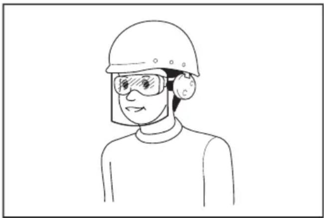
natural_image
Line drawing of a person wearing a hard hat and safety goggles (no text or symbols)It is an employer's responsibility to enforce the use of appropriate safety protective equipments by the tool operators and by other persons in the immediate working area.
Power tool use and care
- Do not force the power tool. Use the correct power tool for your application. The correct power tool will do the job better and safer at the rate for which it was designed.
- Do not use the power tool if the switch does not turn it on and off. Any power tool that cannot be controlled with the switch is dangerous and must be repaired.
- Disconnect the plug from the power source and/or remove the battery pack, if detachable, from the power tool before making any adjustments, changing accessories, or storing power tools. Such preventive safety measures reduce the risk of starting the power tool accidentally.
- Store idle power tools out of the reach of children and do not allow persons unfamiliar with the power tool or these instructions to operate the power tool. Power tools are dangerous in the hands of untrained users.
- Maintain power tools and accessories. Check for misalignment or binding of moving parts,
breakage of parts and any other condition that may affect the power tool's operation. If damaged, have the power tool repaired before use. Many accidents are caused by poorly maintained power tools.
- Keep cutting tools sharp and clean. Properly maintained cutting tools with sharp cutting edges are less likely to bind and are easier to control.
- Use the power tool, accessories and tool bits etc. in accordance with these instructions, taking into account the working conditions and the work to be performed. Use of the power tool for operations different from those intended could result in a hazardous situation.
- Keep handles and grasping surfaces dry, clean and free from oil and grease. Slippery handles and grasping surfaces do not allow for safe handling and control of the tool in unexpected situations.
- When using the tool, do not wear cloth work gloves which may be entangled. The entanglement of cloth work gloves in the moving parts may result in personal injury.
Battery tool use and care
- Recharge only with the charger specified by the manufacturer. A charger that is suitable for one type of battery pack may create a risk of fire when used with another battery pack.
- Use power tools only with specifically designated battery packs. Use of any other battery packs may create a risk of injury and fire.
- When battery pack is not in use, keep it away from other metal objects, like paper clips, coins, keys, nails, screws or other small metal objects, that can make a connection from one terminal to another. Shorting the battery terminals together may cause burns or a fire.
- Under abusive conditions, liquid may be ejected from the battery; avoid contact. If contact accidentally occurs, flush with water. If liquid contacts eyes, additionally seek medical help. Liquid ejected from the battery may cause irritation or burns.
- Do not use a battery pack or tool that is damaged or modified. Damaged or modified batteries may exhibit unpredictable behaviour resulting in fire, explosion or risk of injury.
- Do not expose a battery pack or tool to fire or excessive temperature. Exposure to fire or temperature above 130 °C may cause explosion.
- Follow all charging instructions and do not charge the battery pack or tool outside the temperature range specified in the instructions. Charging improperly or at temperatures outside the specified range may damage the battery and increase the risk of fire.
Service
- Have your power tool serviced by a qualified repair person using only identical replacement parts. This will ensure that the safety of the power tool is maintained.
-
Never service damaged battery packs. Service of battery packs should only be performed by the manufacturer or authorized service providers.
-
Follow instruction for lubricating and changing accessories.
Cordless steel rod cutter safety warnings
- Hold the tool securely while it is in use. If the tool is not held securely, you may be injured.
- Keep your hands and face away from the moving parts. They may cause an injury.
- Release the Switch trigger immediately to stop operation when the tool is out of order or makes an abnormal sound during use. Have it inspected and repaired by an authorized service center. Failure to do so may result in damage or injury.
- If you drop or strike the tool, check carefully that the body is not damaged, cracked, or deformed. Any such damage could cause injury.
- This tool is an electro-hydraulic tool. The oil reservoir was filled before delivery. Do not add oil unless the tool operates abnormally.
- Metal cutting blades have sharp edges. Handle them carefully to avoid being cut.
- Damaged, deformed or cracked blades may cause serious accidents as well as impair operation. Replace with new genuine blades immediately.
SAVE THESE INSTRUCTIONS.
WARNING: DO NOT let comfort or familiarity with product (gained from repeated use) replace strict adherence to safety rules for the subject product.
MISUSE or failure to follow the safety rules stated in this instruction manual may cause serious personal injury.
Important safety instructions for battery cartridge
- Before using battery cartridge, read all instructions and cautionary markings on (1) battery charger, (2) battery, and (3) product using battery.
- Do not disassemble or tamper with the battery cartridge. It may result in a fire, excessive heat, or explosion.
- If operating time has become excessively shorter, stop operating immediately. It may result in a risk of overheating, possible burns and even an explosion.
- If electrolyte gets into your eyes, rinse them out with clear water and seek medical attention right away. It may result in loss of your eyesight.
- Do not short the battery cartridge:
(1) Do not touch the terminals with any conductive material.
(2) Avoid storing battery cartridge in a container with other metal objects such as nails, coins, etc.
(3) Do not expose battery cartridge to water or rain.
A battery short can cause a large current flow, overheating, possible burns and even a breakdown.
6. Do not store and use the tool and battery cartridge in locations where the temperature may reach or exceed 50 °C (122 °F).
7. Do not incinerate the battery cartridge even if it is severely damaged or is completely worn out. The battery cartridge can explode in a fire.
8. Do not nail, cut, crush, throw, drop the battery cartridge, or hit against a hard object to the battery cartridge. Such conduct may result in a fire, excessive heat, or explosion.
9. Do not use a damaged battery.
10. The contained lithium-ion batteries are subject to the Dangerous Goods Legislation requirements.
For commercial transports e.g. by third parties, forwarding agents, special requirement on packaging and labeling must be observed.
For preparation of the item being shipped, consulting an expert for hazardous material is required. Please also observe possibly more detailed national regulations.
Tape or mask off open contacts and pack up the battery in such a manner that it cannot move around in the packaging.
11. When disposing the battery cartridge, remove it from the tool and dispose of it in a safe place. Follow your local regulations relating to disposal of battery.
12. Use the batteries only with the products specified by Makita. Installing the batteries to non-compliant products may result in a fire, excessive heat, explosion, or leak of electrolyte.
13. If the tool is not used for a long period of time, the battery must be removed from the tool.
14. During and after use, the battery cartridge may take on heat which can cause burns or low temperature burns. Pay attention to the handling of hot battery cartridges.
15. Do not touch the terminal of the tool immediately after use as it may get hot enough to cause burns.
16. Do not allow chips, dust, or soil stuck into the terminals, holes, and grooves of the battery cartridge. It may cause heating, catching fire, burst and malfunction of the tool or battery cartridge, resulting in burns or personal injury.
17. Unless the tool supports the use near high-voltage electrical power lines, do not use the battery cartridge near high-voltage electrical power lines. It may result in a malfunction or breakdown of the tool or battery cartridge.
18. Keep the battery away from children.
CAUTION: Only use genuine Makita batteries. Use of non-genuine Makita batteries, or batteries that have been altered, may result in the battery bursting causing fires, personal injury and damage. It will also void the Makita warranty for the Makita tool and charger.
SAVE THESE INSTRUCTIONS.
Tips for maintaining maximum battery life
- Charge the battery cartridge before completely discharged. Always stop tool operation and charge the battery cartridge when you notice less tool power.
- Never recharge a fully charged battery cartridge. Overcharging shortens the battery service life.
- Charge the battery cartridge with room temperature at 10 °C - 40 °C (50 °F - 104 °F). Let a hot battery cartridge cool down before charging it.
- When not using the battery cartridge, remove it from the tool or the charger.
- Charge the battery cartridge if you do not use it for a long period (more than six months).
FUNCTIONAL DESCRIPTION
CAUTION: Always be sure that the tool is switched off and the battery cartridge is removed before adjusting or checking function on the tool.
Installing or removing battery cartridge
⚠️CAUTION: Always switch off the tool before installing or removing of the battery cartridge.
⚠️CAUTION: Hold the tool and the battery cartridge firmly when installing or removing battery cartridge. Failure to hold the tool and the battery cartridge firmly may cause them to slip off your hands and result in damage to the tool and battery cartridge and a personal injury.
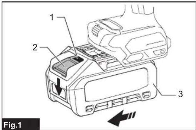
To install the battery cartridge, align the tongue on the battery cartridge with the groove in the housing and slip it into place. Insert it all the way until it locks in place with a little click. If you can see the red indicator as shown in the figure, it is not locked completely.
To remove the battery cartridge, slide it from the tool while sliding the button on the front of the cartridge.
▶ Fig.1: 1. Red indicator 2. Button 3. Battery cartridge
⚠️CAUTION: Always install the battery cartridge fully until the red indicator cannot be seen. If not, it may accidentally fall out of the tool, causing injury to you or someone around you.
⚠️CAUTION: Do not install the battery cartridge forcibly. If the cartridge does not slide in easily, it is not being inserted correctly.
Tool / battery protection system
The tool is equipped with a tool/battery protection system. This system automatically cuts off power to the motor to extend tool and battery life. The tool will
automatically stop during operation if the tool or battery is placed under one of the following conditions.
Overload protection
This protection works when the tool is operated in a manner that causes it to draw an abnormally high current. In this situation, turn the tool off and stop the application that caused the tool to become overloaded. Then turn the tool on to restart.
Overheat protection
This protection works when the tool or battery is overheated. In this situation, let the tool and battery cool before turning the tool on again.
Overdischarge protection
This protection works when the remaining battery capacity gets low. In this situation, remove the battery from the tool and charge the battery.
Protections against other causes
Protection system is also designed for other causes that could damage the tool and allows the tool to stop automatically. Take all the following steps to clear the causes, when the tool has been brought to a temporary halt or stop in operation.
- Make sure that all switch(es) is/are in the off position, and then turn the tool on again to restart.
- Charge the battery(ies) or replace it/them with recharged battery(ies).
- Let the tool and battery(ies) cool down.
If no improvement can be found by restoring protection system, then contact your local Makita Service Center.
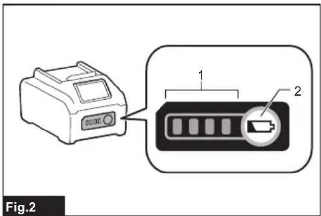
Indicating the remaining battery capacity
Press the check button on the battery cartridge to indicate the remaining battery capacity. The indicator lamps light up for a few seconds.
▶ Fig.2: 1. Indicator lamps 2. Check button
| Indicator lamps Remaining | capacity | ||
| Lighted Off | Blinking | ||
 | 75% to 100% | ||
 | 50% to 75% | ||
 | 25% to 50% | ||
 | 0% to 25% | ||
 | Charge the battery. | ||
 ↑↓ ↑↓ | The battery may have malfunctioned. | ||
NOTE: Depending on the conditions of use and the ambient temperature, the indication may differ slightly from the actual capacity.
NOTE: The first (far left) indicator lamp will blink when the battery protection system works.
OPERATION
Operating procedure
Read, understand and follow all safety instructions and operating procedures. If you do not understand the instructions, or if conditions are not correct for proper operation, do not operate this tool. Consult your supervisor or other responsible person.
WARNING: Before the Battery is inserted into the tool, pull and release the switch trigger to ensure that it returns when released.
The motor is on when the switch trigger is pulled and off when the switch trigger is released.
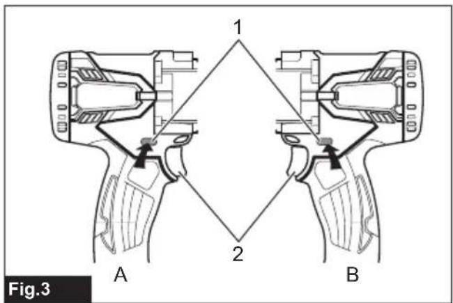
Switch Lock Operation
- Push in the Switch Lock on side A. The Switch is unlocked and the Trigger can be operated.
- Push in the Switch Lock on side B. The Switch is locked and the Trigger cannot be operated.
▶ Fig.3: 1. Switch lock 2. Switch trigger
⚠️CAUTION: The switch trigger should be locked at all times when not in use.
WARNING: Before operation, confirm that the position of the operator, relative to the tool, and the surrounding area is safe for operation. Put on safety glasses and wear protective clothing.
⚠ WARNING: Refer to the tool specifications in this manual and do not cut rebar of size or hardness that exceeds the cutting capacity of the tool.
⚠ WARNING: Do not cut material other than rebar. Please ask the manufacturer if you want to cut other materials.
WARNING: Replace damaged (chipped, broken, cracked) or deformed blades immediately. The blade will not cut true and may fracture or break causing serious personal injury.
Cutting Procedure
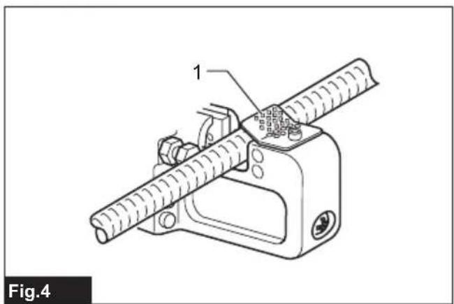
WARNING: Never use the tool without the protector in place. Failure to do so can cause serious personal injury.
▶ Fig.4: 1. Protector
WARNING: Protector is an equipment to prevent fragments from being projected towards the operator. It does not prevent a projection to the axial direction of the rebar. Position yourself so that the protector blocks the fragments.
WARNING: In some figures the protector is not shown, but it is for showing the inside of the protector. Always use the protector in place.
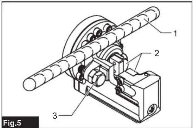
- Position the rebar to be cut between the blades.
▶ Fig.5: 1. Rebar 2. Blades 3. Hold bolt
Adjust the hold bolt according to the diameter of the rebar to be cut so that the rebar is at 90 degrees to the blades. The hold bolt supports the rebar and keeps it perpendicular to the blades when cutting.
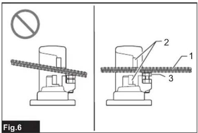
▶ Fig.6: 1. Rebar 2. Blades 3. Hold bolt
WARNING: When cutting rebar, adjust the hold bolt according to the diameter of the rebar to be cut so that the rebar is at 90 degrees to the blades. Without this adjustment, the cut piece may fly off and cause serious injury to the operator or bystanders. Never fail to check the position of the operator relative to the tool and confirm the safety of the operator and surrounding area.
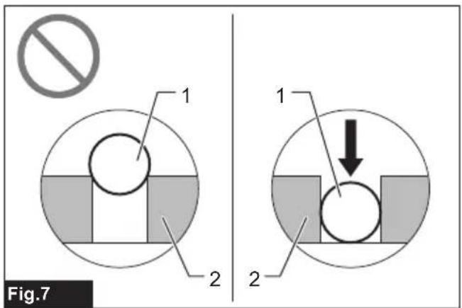
- Position the rebar deep enough between the blades so that it does not touch the protector.
▶ Fig.7: 1. Rebar 2. Blades
WARNING: If the rebar to be cut is not positioned fully between the blades, the blades will be damaged; the rebar will be ejected violently and may cause serious personal injury.
WARNING: Do not cut rebar when the piece to be cut off is less than 200 mm in length. Cutting shorter length may cause the rebar to fly off during cut and may result in serious personal injury.
▶ Fig.8: 1. Rebar 2. Blade 3. Hold bolt 4. More than 200 mm
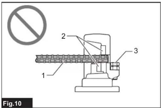
WARNING: Do not cut rebar when it is not properly supported by the hold bolt. When cutting, hold the rebar on the hold bolt side. If not, the cut piece may fly off and cause serious injury to the operator or bystanders.
▶ Fig.9
▶ Fig.10: 1. Rebar 2. Blades 3. Hold bolt
- Push in the Switch Lock on Side A. The switch is unlocked and the trigger can be operated.
-
Press the switch trigger to start cutting operation. The Cutter Rod will move forward to cut the rebar. Keep the Switch depressed until the Cutter Rod stops at the end of its stroke.
-
Release the switch trigger when the cut is completed and the Cutter Rod has reached the end of its stroke. The Cutter Rod will then return automatically to its starting position. The Cutter Rod will not return if the stroke is not completed. Similarly the Cutter Rod will not be able to move forward again until after it returns completely to its starting position. Press the switch to start the next cut, only after the Cutter Rod completely returns to its starting position and stops.
WARNING: When cutting rebar of a high tensile strength the cut piece may fly off and cause serious injury to the operator. Wear safety glasses and confirm that the surrounding area is safe before starting operation.
⚠ WARNING: Keep your hands and face away from the blades, the moving parts and the cutting area, during operation. Remove the Battery from the tool immediately after use.
NOTE: If the temperature of the tool housing exceeds 70^ C ( 160^ F), the tool capacity decreases. In such a case, stop the use and allow the tool to cool down.
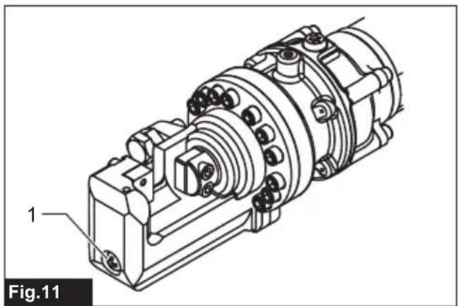
NOTE: Keep the air hole in the end of the Bar Holder clear of dirt and debris. The air hole controls the internal pressure and should not be obstructed.
▶ Fig.11: 1. Air hole
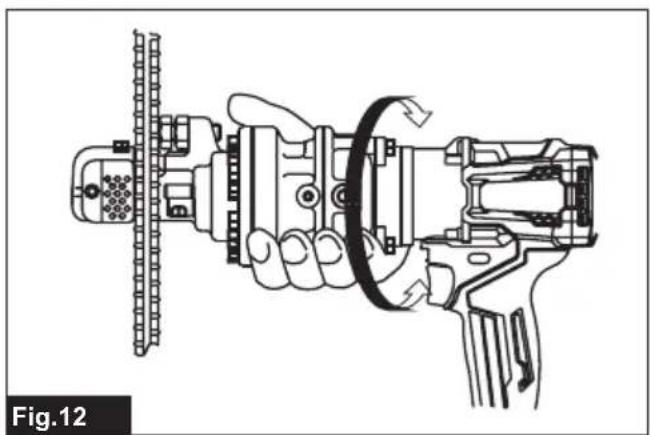
Rotating Function of Motor
The Motor Body can be rotated through 360 degrees, in either direction, during operation. This feature is particularly useful when working in awkward or narrow areas as it allows the operator to position the tool in the best position for easy operation.
▶ Fig.12
Return Valve Operation
The function of the Return Valve is to allow the Cutter Rod to return to the starting position if it is unable
complete a cut or becomes jammed. Using supplied hex wrench, loosen the return valve about a turn in anticlockwise direction. This will release the oil pressure and allow the Cutter Rod to return. Retighten the Return Valve once the Cutter Rod is fully returned and before starting the next operation.
▶ Fig.13: 1. Hex wrench 2. Return Valve
Blades replacement procedure
If the cutting edges of the blades are chipped, cracked, deformed, or damaged in any way, their cutting ability will be reduced. Cutting under such conditions may cause further damage and result in personal injury. The blades should be replaced as a set immediately if any damage is found.
⚠ WARNING: When replacing the blades, ensure that the Battery is removed from the tool to prevent accidental operation.
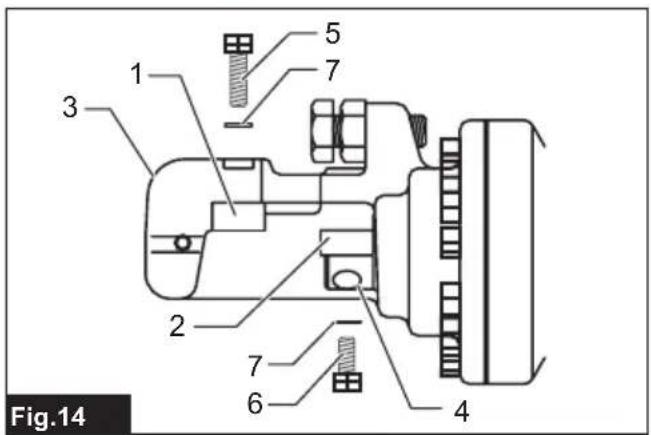
Ensure that Blade A, on the Bar Holder and Blade B, on the Cutter Rod are fitted in their correct respective positions.
▶ Fig.14: 1. Blade A (Thicker blade) 2. Balde B (Thinner blade) 3. Bar holder 4. Cutter rod 5. Bolt (Longer) 6. Bolt (Shorter) 7. Washer
- Undo the bolts and the washers that hold Blade A and Blade B.
- Remove dirt and clean the surfaces where the new blades are to be fitted.
- Fit Blade A to the Bar Holder and Blade B to the Cutter Rod. Replace bolts and washers and tighten firmly.
WARNING: The bolts that hold Blade A and Blade B should be tightened regularly. If the bolts become loose the Blades may be damaged and may cause personal injury.
Type of spare blade and detachment
Securing bolts should be firmly tightened. Confirm periodically that the blade is tightened properly.
▶ Fig.15: 1. Blade A on bar holder 2. Blade B on cutter rod 3. Spare blade
Spare blade size
| Model A (Cutter head) B (Cutter rod) | ||
| SC001G (Φ3 - Φ16) | 22 × 17 × 9 mm (Bolt size 5 mm, two holes) | 22 × 17 × 8 mm (Bolt size 5 mm, two holes) |
* Use this table to identify the correct blades for your model.
NOTE: Use only genuine Makita blades.
Adding oil
This Cordless Steel Rod Cutter is electro-hydraulic. When shipped from the factory, it was filled with oil. Do not attempt to add oil as long as the tool performs well. Over a period of time the oil level will gradually go down. Eventually this will cause a noticeable dropping off in performance. When this happens add oil as follows.
-
Place some rebar between the blades and pull the switch trigger.
-
Release the switch trigger just before the cut is completed to stop the tool.
- Remove the Battery from the tool, so that the Blades cannot be moved accidentally.
- Remove the Bolt (SB10x15) which caps the oil filler hole. Add the oil, being careful not to allow any oil to spill into the motor.
- Replace the Bolt (SB10x15) and tighten securely.
-
Reinsert the Battery into the tool and complete the cutting operation.
-
Repeat the above procedure several times until the oil level remains correct.
CAUTION: Only pure hydraulic oil as recommended by Makita should be used in this tool. Recommended oils include the Makita supplied hydraulic oil, Super Hyrando #46 (JX Nippon Oil & Energy Corp.); Shell Tellus Plus #46 (U.S. Shell); or equivalent spec anti-wear hydraulic oil, ISO Viscosity Grade 46. Do not use other oils as these may cause damage to the seals and other internal machine parts.
TROUBLESHOOTING
⚠ WARNING: Remove battery before working on machine.
| State of abnormality Probable cause | (malfunction) Remedy | |
| Cutter Rod will not extend. Insufficient | oil. Top up oil. (Refer to “Adding Oil”) | |
| Cutter Rod has not returned completely due to build up of debris between Cutter Rod and Bar Holder. | Manually push back Cutter Rod.Remove debris and clean. | |
| Cutter Rod has not returned completely due to damage to the Cutter Rod. | Replace Cutter Rod. | |
| Cutter Rod has not returned completely due to loose or damaged Blades. | Tighten Blade bolts.Replace Blades. | |
| Cutter Rod has not returned completely due to weak Return spring. | Replace Return spring. | |
| Insufficient power to cut rebar. Insufficient oil. Top up oil. (Refer to “Adding Oil”) | ||
| Oil leaks. Oil leveller Bladder, damaged or broken. | Replace. | |
| Replace Back-Up Ring and O-ring.Replace Cutter Rod/Bar Holder. | ||
| Replace O-ring. | ||
| Replace liner B. | ||
| Tighten bolts. | ||
| Motor not moving. Motor slow or erratic. | Voltage incorrect. Charge Battery. | |
| Battery at end of working life. Replace Battery. | ||
| DC Motor damaged by over-heating. Replace DC Motor. | ||
| DC Motor bearings or gear damaged or broken. | Replace bearings or gear. | |
NOTE: The internal components of the pump and piston area have very close tolerances and are sensitive to damage from dust, dirt, contamination of the hydraulic fluid or improper handling. The disassembly of the pump housing requires special tools and training, and should only be attempted by qualified repair personnel that have been properly trained and have the right tools. The improper servicing of electrical components can lead to conditions that could cause serious injury. The pump, piston components and all electrical parts should be serviced only by authorized repair shop, dealer or distributor.
MAINTENANCE
⚠️CAUTION: Always be sure that the tool is switched off and the battery cartridge is removed before attempting to perform inspection or maintenance.
NOTICE: Never use gasoline, benzine, thinner, alcohol or the like. Discoloration, deformation or cracks may result.
To maintain product SAFETY and RELIABILITY, repairs, any other maintenance or adjustment should be performed by Makita Authorized or Factory Service Centers, always using Makita replacement parts.
OPTIONAL ACCESSORIES
⚠️CAUTION: These accessories or attachments are recommended for use with your Makita tool specified in this manual. The use of any other accessories or attachments might present a risk of injury to persons. Only use accessory or attachment for its stated purpose.
If you need any assistance for more details regarding these accessories, ask your local Makita Service Center.
• Makita genuine battery and charger
NOTE: Some items in the list may be included in the tool package as standard accessories. They may differ from country to country.
SPÉCIFICATIONS
natural_image
Line drawing of a person wearing a hard hat and safety goggles (no text or symbols)natural_image
Line drawing of a person wearing a hard hat and safety goggles (no text or symbols)▶ Abb.4: 1. Schutzbügel
natural_image
Line drawing of a person wearing a helmet and safety goggles (no text or symbols)VEILIGHEIDSWAAR- SCHUWINGEN
natural_image
Line drawing of a person wearing a hard hat and safety goggles (no text or symbols)OPTIONELE ACCESSOIRES
natural_image
Line drawing of a person wearing a helmet and safety goggles (no text or symbols)natural_image
Line drawing of a person wearing a helmet and safety goggles (no text or symbols)natural_image
Line drawing of a person wearing a hard hat and safety goggles (no text or symbols)natural_image
Line drawing of a person wearing a helmet and safety goggles (no text or symbols)natural_image
Line drawing of a person wearing a helmet and safety goggles (no text or symbols)▶ 圖片9 ▶ 圖片10: 1. 鋼筋 2. 刀片 3. 固定螺栓