
Icon Line 170 - Slicer Berkel - Free user manual and instructions
Find the device manual for free Icon Line 170 Berkel in PDF.


| Product type | Electric slicer |
| Brand | Berkel |
| Model | Icon Line 170 |
| Dimensions (W x D x H) | 520 x 326 x 455 mm |
| Weight | 10.5 kg |
| Power supply | 230 V, 50 Hz |
| Motor power | 0.19 kW |
| Blade diameter | 170 mm |
| Circular cutting capacity | 140 mm |
| Rectangular cutting capacity | 200 x 140 mm |
| Adjustable slice thickness | 0 - 18 mm |
| Blade material | Stainless steel |
| On/Off function | Adjustment knob with ON/OFF function |
| Emergency stop button | Yes (STOP button) |
| Blade guard | Removable blade guard disc |
| Safety | CE locking system for cleaning |
| Cleaning | Removable parts (food pusher, blade guard disc); food pusher dishwasher safe |
| Maintenance | Lubrication of slide bars, blade sharpening (optional sharpener) |
| Use | Cold cuts, boneless meat, hard cheese, semi-hard bread, fruits, vegetables, fish |
| Warranty | 24 months |
Frequently Asked Questions - Icon Line 170 Berkel
User questions about Icon Line 170 Berkel
0 question about this device. Answer the ones you know or ask your own.
Ask a new question about this device
Download the instructions for your Slicer in PDF format for free! Find your manual Icon Line 170 - Berkel and take your electronic device back in hand. On this page are published all the documents necessary for the use of your device. Icon Line 170 by Berkel.
USER MANUAL Icon Line 170 Berkel
ELEVATING YOUR PASSION, SINCE 1898.
ELECTRIC SLICERS
ICON LINE 170

IT MANUALE D'USO
EN USER MANUAL
FR MANUEL D'INSTRUCTIONS
CS NÁVOD K POUŽITÍ
DA BETJENINGSVEJLEDNING
natural_image
Technical line drawing of a motor or generator component with no visible text or symbols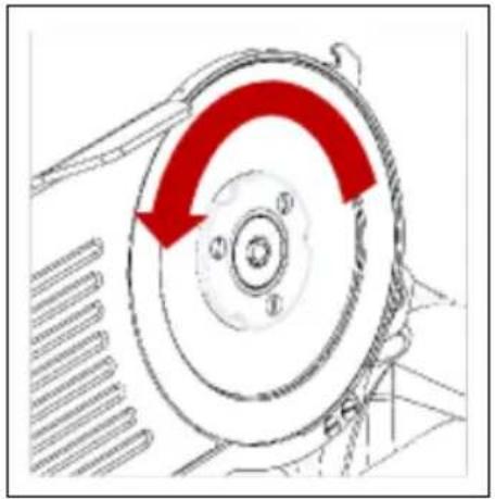
natural_image
Diagram of a mechanical component with red curved arrows indicating rotation or direction (no text or symbols)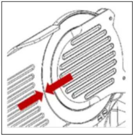
natural_image
Diagram of a mechanical component with red arrows indicating direction, no text or symbols present(D) (E)
natural_image
Technical line drawing of a mechanical device with red arrows indicating motion or force direction (no text or symbols)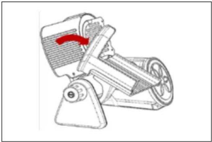
natural_image
Technical line drawing of a mechanical device with a red arrow indicating motion or force (no text or symbols)(F) (G) (H)
natural_image
Technical line drawing of a mechanical device with red arrows indicating motion or flow direction (no text or symbols)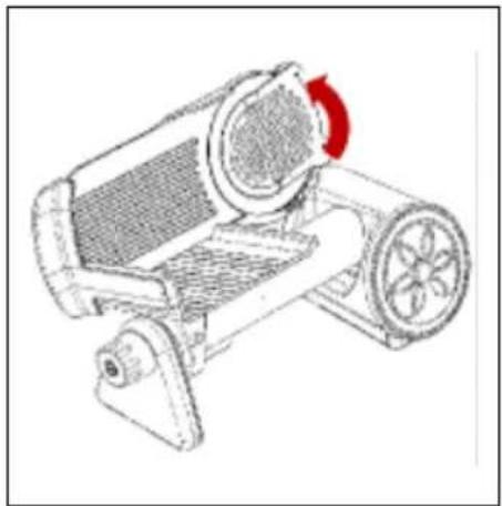
natural_image
Technical line drawing of a mechanical device with a red arrow indicating rotation (no text or symbols)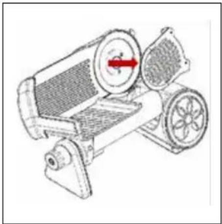
natural_image
Technical line drawing of a mechanical device with no visible text or symbols(I) (L) (M)
natural_image
Hand holding a circular mechanical component with red directional arrows indicating rotation or movement (no text or symbols)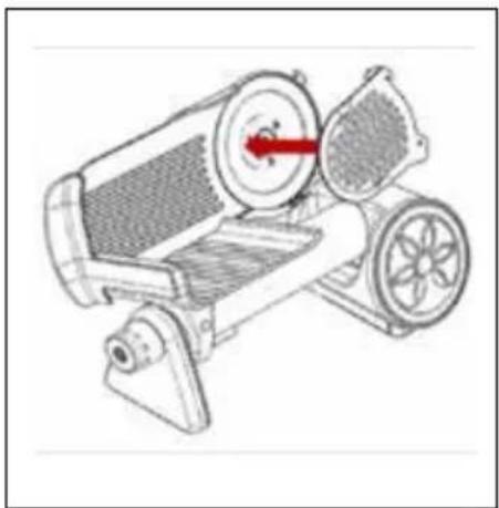
natural_image
Technical line drawing of a mechanical device with gears and a central shaft (no text or symbols)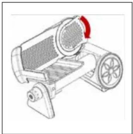
natural_image
Technical line drawing of a mechanical device with a red circular arrow indicating rotation (no text or symbols)Sommario
- NORMATIVE DI CONFORMITÀ 6
- ELENCO SEGNI E SIMBOLI PRESENTI SU MACCHINA E IMBALLO 6
- DESCRIZIONE 7
- COMPONENTI PRINCIPALI MODELLO ICON LINE 7
- PRESCRIZIONI DI SICUREZZA 8
5.1 POSIZIONE DI SICUREZZA 8 - RESPONSABILITÀ COSTRUTTORE 9
- IMBALLO E SMALTIMENTODELL'IMBALLO 9
- INSTALLAZIONE 10
8.1 CONDIZIONI AMBIENTALI 10 - ISTRUZIONI D'USO 10
- COSA AFFETTARE E COSA NON AFFETTARE 10
- PULIZIA 11
11.1 PRODOTTI PER LA PULIZIA 11
11.2 SICUREZZA BLOCCO CE 11 - PARTI RIMOVIBILI: RIMOZIONE, PULIZIA E MONTAGGIO 11
12.1 PRESSAMERCE 11
12.2 COPRILAMA 11 - MANUTENZIONE 12
- RILEVAMENTO DEI GUASTI/RISOLUZIONE DEI PROBLEMI E RIPARAZIONI 12
- SMALTIMENTO DEL DISPOSITIVO 13
- ASSISTENZA CLIENTI 13
- GARANZIA E RESPONSABILITA' 13
- CARATTERISCTICHE TECNICHE DEL PRODOTTO - SCHEDA TECNICA 14
- SCHEMA ELETTRICO 15
ICON LINE
https://www.theberkelworld.com
https://www.theberkelworld.com
1. NORMATIVE DI CONFORMITÀ
4. COMPONENTI PRINCIPALI MODELLO ICON LINE
natural_image
Technical line drawing of a mechanical clamp or bracket component with dimension labels D and E (no text or symbols present)Index
- COMPLIANCE REGULATIONS 18
- LIST OF SIGNS AND SYMBOLS ON THE MACHINE AND PACKAGING 18
- DESCRIPTION 19
- MAIN COMPONENTS MODEL ICON LINE 19
- SAFETY REQUIREMENTS 20
5.1 SAFETY POSITION 20 - MANUFACTURER'S RESPONSIBILITY 21
- PACKAGING AND PACKAGING DISPOSAL 21
- INSTALLATION 21
8.1 ENVIRONMENTAL CONDITIONS 22 - INSTRUCTIONS FOR USE 22
- WHAT TO SLICE AND WHAT NOT TO SLICE 22
- CLEANING 22
11.1 CLEANING PRODUCTS 22
11.2 CE LOCK SAFETY 23 - REMOVABLE PARTS: REMOVAL, CLEANING, AND ASSEMBLY 23
12.1 PUSHER 23
12.2 BLADE COVER 23 - MAINTENANCE 23
- TROUBLESHOOTING AND REPAIRS 24
- DEVICE DISPOSAL 25
- CUSTOMER SERVICE 25
- WARRANTY AND LIABILITY 25
- PRODUCT TECHNICAL SPECIFICATIONS - TECHNICAL DATA SHEET 26
19.WIRING DIAGRAM 27
ICON LINE
This specific User Manual for the Icon Line slicers aims to inform the operator about the installation, use, cleaning, maintenance, assistance, and warranty of the product.
Berkel Slicer, manufactured by Berkel Ind. Pvt. Ltd. Chennai and imported by Van Berkel International S.r.l. located at via Ugo Foscolo 22, Oggiona S. Stefano (VA) 21040.
Email: info@berkelinternational.com
Website: https://www.theberkelworld.com
The Icon Line
Slicer Manual is also available in digital format, accessible directly on our website in the Icon Line Section.
Website:
https://www.theberkelworld.com
1. COMPLIANCE REGULATIONS
The Icon Line slicer described in this manual complies with the European hygiene and safety standards imposed by the latest regulations:
2014/35/EU Low Voltage Directive
2014/30/EU Electromagnetic Compatibility Directive 2012/19/EU Waste Electrical and Electronic Equipment (WEEE) Directive
2011/65/EU Restriction of Hazardous Substances (RoHS) Directive
1935/2004 Regulation on materials and articles intended to come into contact with food EN 60335-1/ EN 60335-2-14 Safety of household and similar electrical appliances
2. LIST OF SIGNS AND SYMBOLS ON THE MACHINE AND PACKAGING
MACHINE SYMBOLS:

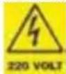
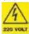
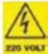
Voltage danger of
electric shock

Grounding Protec-
tion against electric shock / Stability of electrical system
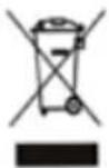
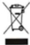
Crossed-out bin indicates that the product must not be disposed of with the general household waste

MOCA (Materials and Objects in contact with food) indicates that the material or object is safe for use in contact with food.
PACKAGING SYMBOLS:

Handle with care
the contents of the package are fragile and must be handled carefully to avoid damage.

Fragile indicates that the contents of the package are delicate and must be handled with extreme care.

Protect from rain and moisture indicates that the contents must be protected from water and moisture.

Orientation arrows correct direction in which a package or object should be placed or handled

Flammable indicates that the contents of the package or container are highly flammable and should be handled with extreme caution.

Recyclable packaging indicates that the packaging can be recycled and should be disposed of in the appropriate recycling containers.
3. DESCRIPTION
Dear Customer,
Thank you for choosing our Icon Line product; we trust that this choice will fully meet your expectations.
- The purpose of this manual is to provide the customer with all the information regarding the slicer, as well as the instructions for use and maintenance that allow maintaining both the performance and efficiency of the slicer over time.
-This manual must be given to every person responsible
for the use and maintenance of the machine.
-The manual must be kept in good condition and stored in an easily accessible place for quick reference.
-The machines are subject to possible updates and, therefore, may have different parts from those shown; this does not in any way affect the explanations contained in the manual.
-For more information or issues not listed in the manual, please contact Berkel assistance or the dealer (see the "CUSTOMER ASSISTANCE"-
section).

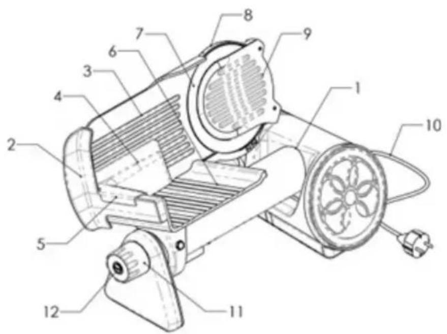
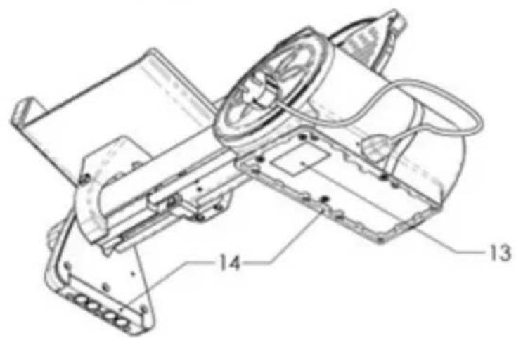
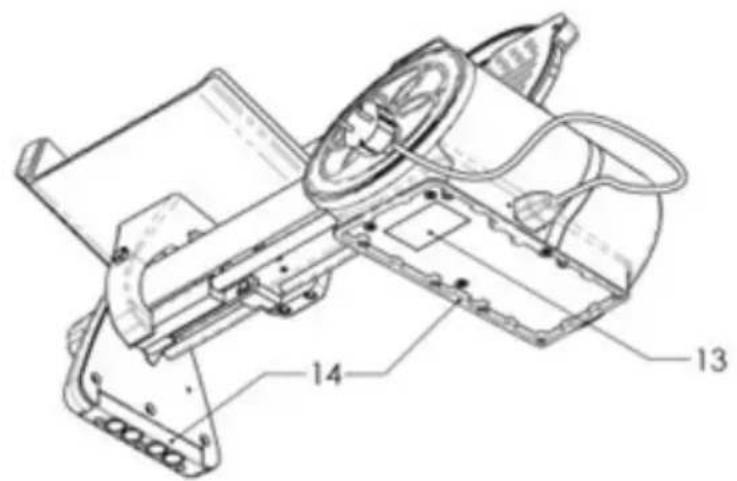
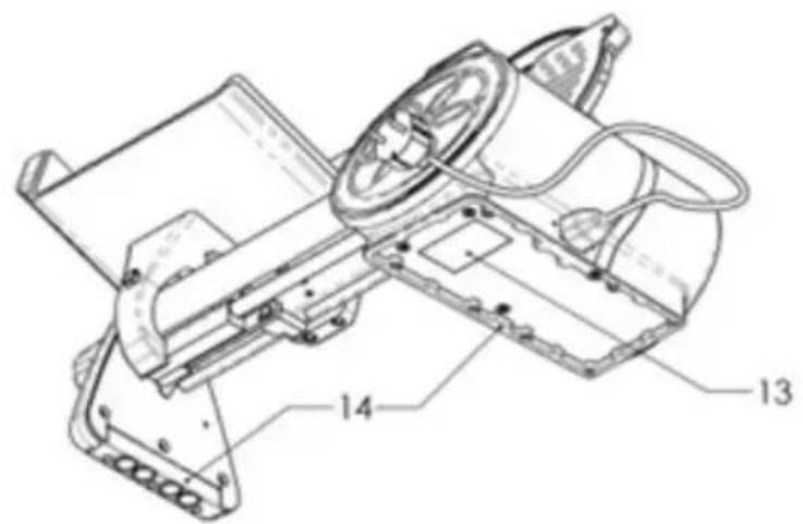
4. MAIN COMPONENTS MODEL ICON LINE
- Base
- Thumb guard
- Gauge Plate
- Pusher
- Product clamp handle
- Sliding meat table
- Blade
- Blade edge guard (black)
- Blade guard
- Power cord
- Slice thickness regulating knob with ON OFF function
- STOP button
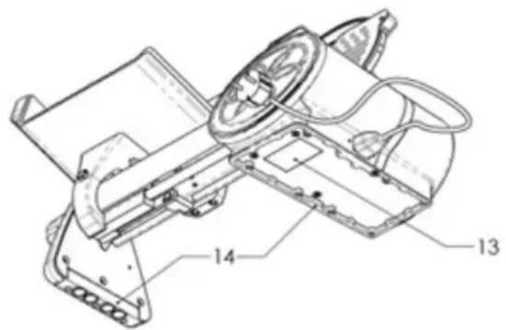
- Data plate
- Foot
5. SAFETY REQUIREMENTS
For the safe use of the purchased device, observe and comply with the following warnings. The instructions of the appliance must be followed as improper use can cause material damage or lead to serious consequences, such as injuries, cuts, and loss of body parts that come into contact with the blade. Read this manual carefully in all its parts before using the slicer.
-Do not use the slicer in any way other than as indicated in this manual.
-Before use, carefully check if the power cord or plug shows any visible external damage. Do not operate the slicer if they are damaged.
-If the power cord is damaged, it must be replaced with a special cord or assembly available from Berkel, the dealer, or the service center.

WARNING! Risk of elec- tric shock! A damaged
cord can cause electric shocks, short circuits, or even fires.
-Ensure that the power cord is securely installed. If the cord gets caught, the slicer may fall off the work surface.
-Always disconnect the slicer from the power outlet by grasping the plug, not the cord.
-Always disconnect the slicer from the power supply if left unattended and before cleaning or maintenance.
-Install the slicer in accordance with the instructions in the 'installation' section.
-Immediately stop the slicer and request the intervention of authorized service personnel in case of abnormal operation, suspected breakages, incorrect movements, or unusual noises.
- Do not touch the slicer with wet or damp hands.
-Do not use the slicer bare-
foot.
-The slicer is not intended for use by persons with reduced physical, sensory, or mental capabilities, or lack of experience and knowledge, unless they have been given supervision or instruction concerning the use of the slicer by a person responsible for their safety.
-Children should be supervised to ensure that they do not play with the slicer.
-The slicer should not be used by children. Keep the slicer and its cord out of reach of children.
-Use the slicer with great concentration and do not get distracted.
-Only slice permitted products (see section "WHAT TO SLICE").
5.1 SAFETY POSITION (Drawing A)
When the slicer is not in use, place it in the safety position as follows:
-Slice thickness regulating knob set to 0 with the blade guard fully closed.
-Pusher positioned close to the blade guard and resting on the product plate

WARNING! RISK OF CUTTING During clean-
ing, maintenance, and slicing operations, keep hands as far away as possible from the unprotected blade area.
-Cleaning and maintenance are intended for the user only and should not be performed by children without supervision.
-Before cleaning or maintenance, disconnect the machine from the power supply and wait for the blade to stop.
IMPORTANT! The slicer should be cleaned regularly with a soft, spongy cloth and mild neutral soap (see the "Cleaning" section for full details).
-Repairs should only be carried out by authorized personnel or Berkel service. Improper repairs can pose risks to the user and void the product warranty and safety.
-Defective components must be replaced with original spare parts or equivalent parts that ensure safety.
-Do not remove, cover, or modify the labels on the slicer body.
-Do not use the slicer as a surface for placing objects unrelated to normal slicing operations.

WARNING! RISK OF ELECTRIC SHOCK! Nev-
er touch live parts.
- Never open the electrical system of the device.
-Do not modify the connections that carry voltage: there is a risk of electric shock.
-Do not alter the electrical/mechanical structure of the slicer: there is a risk of electric shock.
-Do not use the slicer near heat sources.
-The slicer, power cord, and plug must not come into contact with water or other liquids.

WARNING! S H A R P BLADE, RISK OF CUT-
TING
The blade is very sharp, like a knife. When disassembling the blade, ensure absolute caution (see the section "REMOVABLE PARTS: Removal, Cleaning, and Assembly > BLADE").
-Do not touch the blade edge with your fingers, risk of cutting.
-Check that the blade rotates counterclockwise when viewed from the blade cover or user side (Drawing B).
-For slicing, use only the product clamp handle and the pusher.
-Do not use the slicer without the carriage.
-This appliance must be used with the product clamp and the support plate in position. -It is not possible to use the slicer with the plate tilted; the plate must be correctly positioned and secured on the base with the pusher parallel to the blade guard (see the "CE Lock" section).
-It is forbidden to use hands to slice the product.
-Always maintain a safe distance from the blade.
-Do not allow anyone to approach during the slicing operation.

WARNING: Risk of slipping!
The area around the slicer must be dry to avoid slipping.
-Place and remove the product to be sliced on the sliding meat table only when the table is fully retracted and the slice thickness regulating knob is set to safety (at 0 - Fig. A).

WARNING! The motor may overheat! After 10 tes of continuous use, off the machine and let notor cool down.
Allow the machine to rest for at least 30 minutes.

WARNING! Risk of entanglement!
Do not wear loose clothing, open sleeves, or items that can get caught, such as bracelets or similar objects. Use clothing with sleeves secured at the wrist with elastic bands.

WARNING! N or m a
A blade wear can cause an increase in the distance between the blade edge and the blade guard. When this distance exceeds 3 mm, the blade must be replaced. Contact the manufacturer or an Authorized Service Center to request replacement. (Drawing C)
-If the size of the food to be sliced exceeds the "cutting capacity" indicated in the technical data sheets, reduce its size to work safely.
-The slicer cannot be used outdoors and exposed to weather conditions that may damage its integrity.
-The slicer cannot be installed in environments with corrosive or abrasive vapors, fumes, or dust, with a risk of fire or explosion.
-The slicer must be installed near a CEE-compliant power outlet, so it can be easily disconnected for cleaning and maintenance operations.
-The slicer must be connected to a system that complies with current regulations and is equipped with:
Magneto-thermal protection; Automatic differential switch; Grounding system.
-Before connecting, check that the characteristics of the electrical power supply match those indicated on the slicer's data plate.
-This appliance is intended for use in domestic and similar applications. While we do not guarantee its use in the following environments if the staff has not been properly instructed or has not read this user manual:
Staff kitchen areas, shops, offices, and other work environments;
Hotels, motels, bed and breakfasts, farmhouses, and other accommodation facilities, made available to guests.
6. MANUFACTURER'S RESPONSIBILITY
The manufacturer declines any responsibility arising from:
-Improper use;
-Failure to observe the instructions contained in this instruction manual;
-Use of the slicer by personnel who have not read and fully understood the contents of
this manual;
-Modifications and/or repairs carried out by the user or unauthorized personnel;
-Use of non-original spare parts or parts not specific to the slicer model;
The transfer of the slicer automatically voids the manufacturer's responsibility if it is not accompanied by this instruction manual. The primary text of this instruction manual, written in Italian, represents the only reference point for resolving any interpretative disputes.
7. PACKAGING AND PACKAGING DISPOSAL
Remove the device from the box;
Remove the components from the packaging;
Remove the user manual and place it in a convenient area near the machine;
Remove the protective card-board from the blade guard;
Take out the power cord contained in a separate small box inside the packaging and connect it to the machine;
IMPORTANT! It is recommended to keep the original packaging for the entire warranty period to properly pack and transport the device if necessary.
The packaging protects the slicer during transport. The packaging materials are easily recyclable in regular household waste or at the local recycling center.
8. INSTALLATION
Install the slicer on a well-leveled, smooth, dry work surface suitable for supporting the slicer and the product to be sliced.
IMPORTANT! If the slicer is not properly installed, it can pose a danger due to unstable conditions; these increase the risk of
impact and crushing for both the operator and people near the work area.
IMPORTANT! Ensure there are no obstructions to the movement of the sliding meat table and the loading of the product to be sliced on the table; if there are, remove them.
Do not place the slicer over heat sources, such as electric plates, or near flames.
The slicer cannot be installed recessed into a wall or in a wall cabinet.
8.1 ENVIRONMENTAL CONDITIONS
-Operating temperature from
-5^ C to +40^ C
-Maximum humidity 95%
-Operating altitude: below 2000 m
9. INSTRUCTIONS FOR USE
Note: The numbers in this paragraph refer to section "4. MAIN COMPONENTS MODEL ICON LINE"
-
Insert the power cable into the power outlet.
-
Fully retract the carriage tray (6) towards the operator, in the loading position.
-
Remove the food pusher (4).
-
Place the food to be sliced on the tray against the vertical edge, operator side. Secure the product with the food pusher, applying slight pressure towards the blade.
-
Adjust the slice thickness using the adjustment knob with ON/OFF function (11), the blade activates (7).
-
Grasp the handle of the food pusher (5) and start the cutting movement by pushing the carriage forward (towards the blade) and backward.
-
At the end of the slicing operations, remove the sliced product, secure the thick-
ness adjustment knob, turn off the blade, and retract the carriage.
- If an immediate stop of the blade movement is necessary, press the STOP button (12)
- At the end of the cutting operations, it is essential to clean the slicer by first removing any remaining food residues (see chapter "Cleaning").
WARNING! Food residues left after using the slicer, if not properly removed, could deteriorate and contaminate the sliced products subsequently.
10. WHAT TO SLICE AND WHAT NOT TO SLICE
WHAT TO SLICE:
-Cold cuts (cooked, raw, smoked, and cured)
-Boneless meat such as roasts (cooked or raw at a temperature not lower than +3°C and not higher than +40°C)
-Carpaccio
-Semi-hard bread with or without seeds
- Semi-hard cheeses
NOTICE: Slicing cheese may not guarantee a uniform and precise slice due to possible adherence of the product to the blade.
-Fish fillets (boneless, cooked or raw at a temperature not lower than -3°C and not higher than +40°C)
-Fruit
-Vegetables
Refer to the "Technical Data Sheet" section for detailed slicing capacity of the slicer.
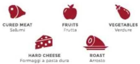

CARPACCIO

BREAD
WARNING! Do not attempt to slice prohibit-products!
-Frozen or deep-frozen foods
-Foods containing bones or pits
-Hard bread
-Non-food products
-Soft or fresh cheeses
-Products with too crumbly consistency
BERKEL DOES NOT GUARANTEE THE SLICING OF PRODUCTS NOT LISTED, ESPECIALLY THOSE WITH INADEQUATE CONSISTENCY.
11. CLEANING
Maintain thorough cleanliness of the slicer. If used, it should be cleaned at least once a day or more frequently if necessary. After a period of inactivity, cleaning is recommended before use.

WARNING! Risk of elec- tric shock
Before proceeding with cleaning the slicer, disconnect the power cord and set the slice thickness regulating knob to safety. (See Chapter "Safety Position")
11.1 CLEANING PRODUCTS
Use only lukewarm water and neutral dish detergent, preferably with a pH of 7-8, using a soft, spongy cloth (e.g., microfiber). Wash the removed parts separately, dry them thoroughly, and reassemble them. (see "Removable Parts" in the next paragraph)
IMPORTANT! It is necessary to dry all washed parts thoroughly, including the blade edge.
DO NOT use abrasive tools
such as hard sponges or semi-rigid nylon brushes to clean the machine.
Do not clean the machine with water jets, steam, or similar methods.

WARNING! Do not put the machine in the dish-er.
The only part that can be washed in the dishwasher is the removable plastic pusher, with a gentle wash and at a low temperature.
11.2 CE LOCK SAFETY
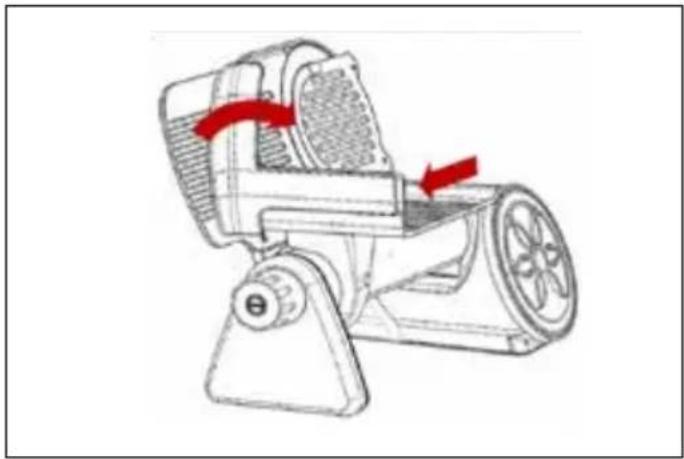
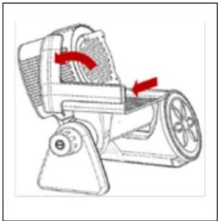
The slicer is equipped with a CE lock that, during the cleaning phase, allows the table to be tilted, ensuring safety. By setting the slice thickness regulating knob to 0 and the table at the start position, it can be tilted; once tilted, the blade guard cannot be opened until the table is returned to the working position. Drawing D-E
CE Lock Action Procedure:
- Ensure the slicer is turned off and the power cord is disconnected.
- Set the slice thickness regulating knob (5) to the safety position (at 0).
- Fully retract the sliding meat table (8) towards the operator.
- Pull the table upwards firmly but gently, rotating it clockwise.
- Clean the affected area with neutral detergent and a soft, spongy cloth.
- After cleaning, pull the carriage tray back to the starting position and rotate it back to the cutting position.
(Drawing F)
12. REMOVABLE PARTS: REMOVAL, CLEANING, AND ASSEMBLY
Pusher
Blade cover

Warning! Before per- ing any Removal, Clean- and Assembly opera- s, ensure that the power is disconnected from power outlet.
12.1 PUSHER
Move the food pusher away from the blade guard and remove it by lifting it upwards.
12.2 BLADE COVER
IMPORTANT! Before starting the cleaning operations, place a soft, spongy cloth on the painted part of the housing to protect it. The blade cover may fall and damage the paint.
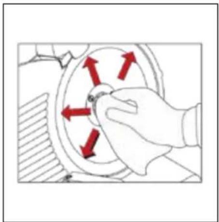
To remove the blade cover, grasp the small protrusion on the lower part of the cover and rotate it upwards counterclockwise (Drawing G-H) until you hear a click indicating it is unlocked; then remove the blade cover by holding it with both hands. Proceed to clean the blade cover, both front and back, and then clean the blade mounted on the machine using a damp, soft, spongy cloth, moving it slowly from the center outward (Drawing I). Then, dry the blade thoroughly to prevent rust.
Reassemble the blade guard by inserting the lower pin into the hole of the blade protection device, rotating it clockwise until it locks.
-The blade guard is stable when the upper pin is inserted into the upper slot and the grooves of the blade and blade guard are parallel. (Drawing L-M)
Important! An undried blade edge can rust.
It is advised not to clean the blade in a clockwise direction but to perform movements
from the center outward to avoid cutting yourself with the blade edge.
13. MAINTENANCE
The periodic maintenance activities that the operator is authorized to perform to preserve the efficiency of the slicer include:
-Lubrication of the sliding bar of the pusher and the sliding bar of the carriage. Use Berkel-branded oil or oil suitable for food contact, possibly with FDA H1 specification. -Blade sharpening: It is advisable to regularly sharpen the blade by purchasing the sharpener separately, also available on our website. To keep the blade functional, we recommend cleaning and drying it regularly (for instructions, see the "Cleaning" section).
| INCONVENIENCE CAUSE | REMEDY | |
| Turning the slice thickness adjustment knob to ON does not start the slicer. | Lack of power supply or faulty control circuit. | Check if the power cable is properly connected to the power outlet. If the problem persists, contact the Berkel Service Center. |
| Pressing the STOP button does not stop the slicer. | Faulty control circuit. Immediately unplug the machine using the power cable and do not use it again. Contact the Berkel Service Center. | |
| Turning the slice thickness adjustment knob to OFF does not turn off the slicer. | Faulty control circuit. Press the STOP button, immediately unplug the machine using the power. cable, and do not use it again. Contact the Berkel Service Center. | |
| Excessive resistance of the machine's sliding bars with slow and hard movement. | Guide lubrication not performed periodically, or performed with incorrect product. | Completely clean the sliding bars from oil or grease residues. Lubricate the sliding bars using Berkel oil or a food-grade oil suitable for contact (FDA H1). |
| Excessive resistance of the slicer's sliding bars with slow and hard movement. | Damaged sliding bar. Contact Berkel's service center. | |
| Rust formation on the blade. Drying not performed periodically and correctly, food residues, water, humidity, steam. | Remove the rust using the sharpen-er (optional, also available on Berkel's website) or contact Berkel's service center for possible blade replacement. | |
| The slicer emits a burning smell | Possible motor overheating. | Turn off and let it rest for 1 hour. If the issue persists, contact Berkel service center. |
| The carriage is in the correct position but does not slide. | Incorrect repositioning of the carriage. Check that the carriage is correctly positioned (see manual section > CE Lock). | |
| The blade guard remains open, the knob does not control the reposition-ing of the blade guard. | Manufacturing defect or damage/im-pact on the machine. | Do not use the machine, pack it by covering and isolating the blade well, and immediately contact Berkel's service center. |
| The slicer does not cut well. Damaged blade. Contact Berkel's service center. | ||
15. DEVICE DISPOSAL

It is not allowed to dispose of the machine with regular household waste. The crossed-out and underlined bin symbol, applied to the product and shown in the manual, indicates that Waste Electrical and Electronic Equipment (WEEE) contains highly polluting but also recoverable materials. Therefore, it is legally required to dispose of the product separately from unsorted urban waste. It is mandatory to check with local authorities or your municipality to learn about collection methods.
16. CUSTOMER SERVICE
If your Berkel device gets damaged, it is recommended to contact your dealer or Berkel customer service at the following numbers:
T: +39 0385 042011
T: +39 0331 214311
or by sending an email to the addresses below:
support@net.berkelinternational.com
technical@berkelinternational.com
No spare parts are provided within the packaging. All repair and replacement activities must be carried out exclusively by personnel authorized by the manufacturer. In case of problems with the device, contact authorized service centers. Avoid repairing the device yourself. Any repair work carried out on the device by unauthorized personnel automatically voids the warranty, even if its duration has not yet expired.
The primary text of this instruction manual, drafted in the Italian language, represents the only point of reference for the resolution of any interpretative disputes.
17. WARRANTY AND LIABILITY
IMPORTANT! It is recommended to keep the original packaging for the entire warranty period to properly pack and transport the device if necessary.
The manufacturer provides the Icon Line with a 24-month warranty from the date of purchase. The warranty covers only defects found when used appropriately and according to the conditions of use specified in the manual. The warranty does not cover defects due to transport, incompetence or negligence of the purchaser, improper installation or positioning, wear and tear, voltage exceeding 10% of the nominal value. Additionally, the warranty does not cover components subject to wear, such as the blade and sharpener wheels, except in the case of evident manufacturing defects. In the event of a legitimate claim, we will proceed as provided by the consumer code. The manufacturer disclaims any direct and indirect liability arising from improper use of the machine. The transfer of ownership of the machine results in the immediate release of all liability by the manufacturer, except for compliance with REGULATION (EU) 2023/1230 OF THE EUROPEAN PARLIAMENT AND OF THE COUNCIL of 14 June 2023 on machinery, and repealing Directive 2006/42/ EC of the European Parliament and of the Council and Council Directive 73/361/ EEC.
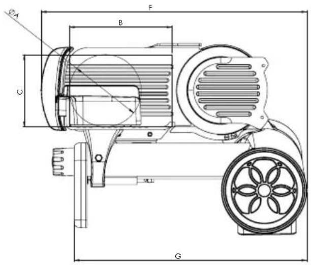
natural_image
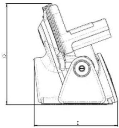
Technical line drawing of a mechanical component with dimension labels D and E (no text or symbols present)| ICON LINE 170 | |
| A 140 mm | |
| B 200 mm | |
| C 140 mm | |
| D 326 mm | |
| E 270 mm | |
| F 520 mm | |
| G 455 mm | |
| SPECIFICATIONS | |
| Circular cutting capacity 140 mm | |
| Rectangular cutting capacity 200x140h mm | |
| Max slice thickness 0 - 18 mm | |
| Blade diameter 170 mm | |
| Weight 10,5 kg | |
| Motor rating 0,19 kW | |
| Electrical specifications 230 V - 50 Hz | |
Note: The technical features and appearance of the products may be subject to changes without prior notice.
Inhaltsverzeichnis
1. KONFORMITÄTSVOR- SCHRIFTEN
https://www.theberkelworld.com
https://www.theberkelworld.com
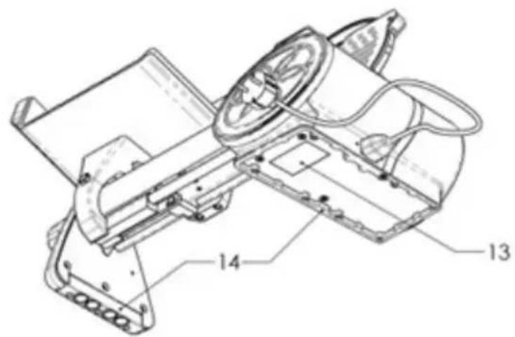
4. HAUPTKOMPONENTEN MODELL ICON LINE
natural_image
Technical line drawing of a mechanical component with dimension labels D and E (no text or symbols present)Sommaire
-
NORMES DE CONFORMITÉ 42
-
LISTE DES SIGNES ET SYMBOLES PRÉSENTS SUR LA MACHINE ET L'EMBALLAGE 42
3.DESCRIPTION 43
-
COMPOSANTS PRINCIPAUX MODÈLE ICON LINE 43
-
PRESCRIPTIONS DE SÉCURITÉ 44
5.1 POSITION DE SÉCURITÉ 44
-
RESPONSABILITÉ DU FABRICANT 45
-
EMBALLAGE ET ÉLIMINATION DE L'EMBALLAGE 46
-
INSTALLATION 46
8.1 CONDITIONS ENVIRONNEMENTALES 46
-
INSTRUCTIONS D'UTILISATION 46
-
QUOI TRANCHER ET QUOI NE PAS TRANCHER 46
-
NETTOYAGE 47
11.1 PRODUITS DE NETTOYAGE 47
11.2 SÉCURITÉ DU BLOCAGE CE 47
- PARTIES AMOVIBLES : DEMONTAGE, NETTOYAGE ET MONTAGE 47
12.1 PRESSE-ALIMENT 47
12.2 DISQUE PARE-LAME 47
-
ENTRETIEN 48
-
DÉTECTION DES PANNES / RÉSOLUTION DES PROBLÈMES ET RÉPARATIONS 48
-
ÉLIMINATION DE L'APPAREIL 49
-
SERVICE CLIENTS 49
-
GARANTIE ET RESPONSABILITÉ 49
-
CARACTÉRISTIQUES TECHNIQUES DU PRODUIT - FICHE TECHNIQUE 50
-
SCHÉMA DE CÂBLAGE 51
ICON LINE
https://www.theberkelworld.com
https://www.theberkelworld.com
1. NORMES DE CONFORMITÉ
4. COMPOSANTS PRINCIPAUX MODÈLE ICON LINE
natural_image
Technical line drawing of a mechanical component with dimension labels D and E (no text or symbols present)Obsah
-
PŘEDPISY PRO DODRŽOVÁNÍ PŘEDPISŮ 54
-
SEZNAM ZNAČEK A SYMBOLŮ NA STROJI A OBALU 54
-
POPIS 55
-
HLAVNÍ KOMPONENTY MODEL ICON LINE 55
-
BEZPEČNOSTNÍ POŽADAVKY 56
5.1 BEZPEČNOSTNÍ POLOHA 56
-
ODPOVĚDNOST VÝROBCE 57
-
BALENÍ A DEMONTÁŽ OBALU 57
-
INSTALACE 57
8.1 ENVIRONMENTÁLNÍ PODMÍNKY 58
-
NÁVOD K POUŽITÍ 58
-
CO KRÁJET A CO NEKRÁJET 58
-
ČIŠTĚNÍ 58
11.1 ČISTICÍ PROSTŘEDKY 58
11.2 BEZPEČNOST ZÁMKU CE 59
- ODNÍMATELNÉ ČÁSTI: DEMONTÁŽ, ČIŠTĚNÍ A MONTÁŽ 59
12.1 TLAKOVÉ KLAPKY 59
https://www.theberkelworld.com
https://www.theberkelworld.com
4. HLAVNÍ KOMPONENTY MODEL ICON LINE
natural_image
Technical drawing of a mechanical clamp or bracket component with dimension labels D and E (no text or symbols present)Indholdsfortegnelse
- OVERENSSTEMMELSESREGLER 66
- LISTE OVER TEGN OG SYMBOLER PÅ MASKINE OG EMBALLAGE 66
- BESKRIVELSE 67
- HOVEDKOMPONENTER MODEL ICON LINE 67
- SIKKERHEDSFORANSTALTNINGER 68
5.1 SIKKERHEDSPOSITION 68 - PRODUCENTENS ANSVAR 69
- EMBALLAGE OG BORTSKAFFELSE AF EMBALLAGE 69
- INSTALLATION 70
8.1 MILJ∅FORHOLD 70 - BRUGSANVISNING 70
- HVAD DER KAN SKÆRES OG HVAD DER IKKE KAN SKÆRES 70
- RENG∅RING 70
11.1 RENG∅RINGSPRODUKTER 70
11.2 SIKKERHEDS BLOKKE CE 71 - AFTAGELIGE DELE: FJERNELSE, RENG∅RING OG MONTERING 71
12.1 PIGPLADE 71
12.2 BESKYTTELSESDÄEKSEL TIL KLINGEN 71 - VEDLIGEHOLDELSE 71
- FEJLFINDING/PROBLEML∅SNING OG REPARATIONER 72
- BORTSKAFFELSE AF ENHEDEN 73
- KUNDESERVICE 73
- ARANTI OG ANSVAR 73
- PRODUKTTEKNISKE SPECIFIKATIONER - TEKNISK BLAD 74
- LEDNINGSDIAGRAM 75
ICON LINE
https://www.theberkelworld.com
2. LISTE OVER TEGN OG SYMBOLER PÅ MASKINE OG EMBALLAGE
MASKINSYMBOLER:
Spænding fare for
elektrisk stød

Jordforbindelse
beskyttelse mod elektrisk stød / stabilitet i elektrisk system
Overkrydset skral-
https://www.theberkelworld.com


4. HOVEDKOMPONENTER MODEL ICON LINE
ADVARSEL! Fare for fastklemning!
HVAD DER KAN SKÆRES:
natural_image
Technical line drawing of a mechanical component with dimension labels D and E (no text or symbols beyond labels)| ICON LINE 170 | |
| A 140 mm | |
| B 200 mm | |
| C 140 mm | |
| D 326 mm | |
| E 270 mm | |
| F 520 mm | |
| G 455 mm | |
| SPECIFICATIONER | |
| Kapacitet rundskæring 140 mm | |
| Kapacitet lineær skæring 200x140h mm | |
| Maks. skivetykkelse 0 - 18 mm | |
| Klingediameter 170 mm | |
| Vægt 10,5 kg | |
| Motor rating 0,19 kW | |
| Elektriske specifikationer 230 V - 50 Hz | |
Índice
https://www.theberkelworld.com
2. LISTA DE SIGNOS Y SÍMBOLOS PRESENTES EN LA MÁQUINA Y EMBALAJE
SIMBOLOGÍA DE LA MÁQUI- NA:
Tensión peligro de
descarga eléctrica

Conexión a tierra
https://www.theberkelworld.com
natural_image
Technical line drawing of a mechanical component with dimension labels D and E (no text or symbols beyond labels)| ICON LINE 170 | |
| A 140 mm | |
| B 200 mm | |
| C 140 mm | |
| D 326 mm | |
| E 270 mm | |
| F 520 mm | |
| G 455 mm | |
| ESPECIFICACIONES | |
| Capacidad (circular) 140 mm | |
| Capacidad (rectangular) 200x140h mm | |
| Capacidad máxima de corte 0 - 18 mm | |
| Diamètre Lame 170 mm | |
| Peso neto 10,5 kg | |
| Potencia motor 0,19 kW | |
| Electromotor 230 V - 50 Hz | |
Sisällysluettelo
- VAATIMUSTENMUKAISUUS 90
- KONEEN JA PAKKAUKSEN SYMBOLIT 90
- KUVAUS 91
- PÄÄKOMPONENTIT MALLI ICON LINE 91
- TURVALLISUUSOHJEET 92
5.1 TURVALLINEN ASENTO 92 - VALMISTAJAN VASTUU 93
- PAKKAUS JA PAKKAUKSEN HÄVITTÄMINEN 93
- ASENNUS 93
8.1 YMPÄRISTÖOLOSUHTEET 94 - KÄYTTÖOHJEET 94
- MITÄ VIIPALOIDA JA MITÄ EI 94
- PUHDISTUS 94
11.1 PUHDISTUSAINEET 94
11.2 CE-LUKON TURVALLISUUS 95 - IRROTETTAVAT OSAT: IRROTUS, PUHDISTUS JA ASENNUS 95
12.1 TUOTTEEN PURISTIN 95
12.2 BESKYTTELSESDÄEKSEL TIL KLINGEN 95 - HUOLTO 95
- VIKOJEN TUNNISTUS/ONGELMIEN RATKAISU JA KORJAUKSET 96
- LAITTEEN HÄVITTÄMINEN 97
- ASIAKASPALVELU 97
- TAKUU JA VASTUU 97
- TUOTTEEN TEKNISET OMINAISUUDET - TEKNISET TIEDOT 98
- KYTKENTÄKAAVIO 99
ICON LINE
https://www.theberkelworld.com
2. KONEEN JA PAKKAUKSEN SYMBOLIT
KONEEN SYMBOLIT:

Jännite sähköiskun
vaara

Maadoitus suojaus
https://www.theberkelworld.com

4. PÄÄKOMPONENTIT MALLI ICON LINE
natural_image
Technical line drawing of a mechanical component with dimension labels D and E (no text or symbols present)Inhoudsopgave
- CONFORMITEITSNORMEN 102
- LIJST VAN TEKENS EN SYMBOLEN OP MACHINE EN VERPAKKING 102
- BESCHRIJVING 103
- HOOFDONDERDELEN MODEL ICON LINE 103
- VEILIGHEIDSVOORSCHRIFTEN 104
5.1 VEILIGHEIDSPOSITIE 104 - VERANTWOORDELIJKHEDEN VAN DE FABRIKANT 105
- VERPAKKING EN VERWIJDERING VAN DE VERPAKKING 106
- INSTALLATIE 106
8.1 OMGEVINGSOMSTANDIGHEDEN 106 - GEBRUIKSINSTRUCTIES 106
- WAT TE SNIJDEN EN WAT NIET TE SNIJDEN 106
- REINIGING 107
11.1 REINICINGSPRODUCTEN 107
11.2 CE-BLOKKERING VEILIGHEID 107 - VERWIJDERBARE DELEN: VERWIJDERING, REINIGING EN MONTAGE 107
12.1 DRUKPLAAT 107
12.2 MESSENBESCHERMER 107 - ONDERHOUD 108
- STORINGEN OPSPOREN/PROBLEMEN OPLOSSEN EN REPARATIES 108
- VERWIJDERING VAN HET APPARAAT 109
- KLANTENSERVICE 109
- GARANTIE EN VERANTWOORDELIJKHEDEN 109
- TECHNISCHE KENMERKEN VAN HET PRODUCT – TECHNISCH BLAD 110
- BEDRADINGSSCHEMA 111
ICON LINE
https://www.theberkelworld.com
2. LIJST VAN TEKENS EN SYMBOLEN OP MACHINE EN VERPAKKING
https://www.theberkelworld.com
4. HOOFDONDERDELEN MODEL ICON LINE
natural_image
Technical drawing of a mechanical component with dimension lines D and E (no text or symbols)| ICON LINE 170 | |
| A 140 mm | |
| B 200 mm | |
| C 140 mm | |
| D 326 mm | |
| E 270 mm | |
| F 520 mm | |
| G 455 mm | |
| SPECIFICATIES | |
| Snijcapaciteit (rond) | 140 mm |
| Snijcapaciteit (rechthoekig) | 200x140h mm |
| Maximale snijdikte | 0 - 18 mm |
| ø Mesdiameter | 170 mm |
| Nettogewicht | 10,5 kg |
| Vermogen motor 0,19 kW | |
| Elektrische specificaties 230 V - 50 Hz | |
Innhold
- OVERENSSTEMMELSESREGLER 114
- LISTE OVER TEGN OG SYMBOLER PÅ MASKIN OG EMBALLASJE 114
- BESKRIVELSE 115
- HOVEDKOMPONENTER MODELL ICON LINE 115
- SIKKERHETSFORSKRIFTER 116
5.1 SIKKERHETSPOSISJON 116 - PRODUSENTENS ANSVAR 117
- EMBALLASJE OG AVHENDING AV EMBALLASJE 117
- INSTALLASJON 117
8.1 MILJ∅FORHOLD 118 - BRUKSANVISNING 118
- HVA SKAL SKJÆRES OG HVA SKAL IKKE SKJÆRES 118
- RENGJ∅RING 118
11.1 RENCJ∅RINGSPRODUKTER 118
11.2 CE-BLOKKERINGSSIKKERHET 119 - AVTAGBARE DELER: FJERNING, RENGJ∅RING OG MONTERING 119
12.1 PRODUKTSKYVER 119
12.2 SKJÆREBLADDEKSEL 119 - VEDLIKEHOLD 119
- FEILS∅KING/PROBLEML∅SNING OG REPARASJONER 120
- AVHENDING AV ENHETEN 121
- KUNDESERVICE 121
- GARANTI OG ANSVAR 121
- RODUKTTEKNISKE SPESIFIKASJONER – TEKNISK DATABLAD 122
- KOBLINGSSKJEMA 123
ICON LINE
https://www.theberkelworld.com
2. LISTE OVER TEGN OG SYMBOLER PÅ MASKIN OG EMBALLASJE
MASKINSYMBOLER:
Spenning
fare for
elektrisk støt

Jordforbindelse
https://www.theberkelworld.com

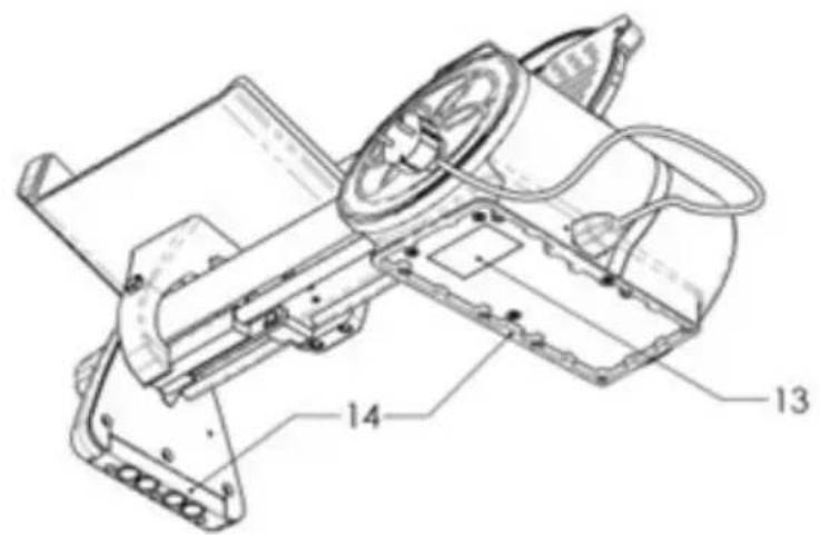
4. HOVEDKOMPONENTER MODELL ICON LINE
HVA SKAL IKKE SKJÆRES:

ADVARSEL! IKKE PR∅V
Å SKJÆRE PRODUKTER SOM IKKE ER TILLATT!
-Frosne eller dypfryste mat-
varer
-Matvarer som inneholder
bein eller kjerner
-Hardt brød
-Ikke-matvarer
-Myk eller fersk ost
-Produkter med for smuldrete konsistens
BERKEL GARANTERER IKKE SKJÆRING AV PRODUKTER SOM IKKE ER LISTET, SPESIELT MED UEGNET KONSISTENS.
11. RENGJ∅RING
natural_image
Technical line drawing of a mechanical component with dimension labels D and E (no text or symbols beyond labels)Sumário
-
NORMAS DE CONFORMIDADE 126
-
LISTA DE SINAIS E SÍMBOLOS PRESENTES NA MÁQUINA E NA EMBALAGEM 126
-
DESCRIÇÃO 127
-
COMPONENTES PRINCIPAIS MODELO ICON LINE 127
-
PRESCRIÇÕES DE SEGURANÇA 128
https://www.theberkelworld.com
2. LISTA DE SINAIS E SÍMBOLOS PRESENTES NA MÁQUINA E NA EMBALAGEM
SÍMBOLOS NA MÁQUINA:

Tensão perigo de
choque elétrico

Ligação à terra
https://www.theberkelworld.com

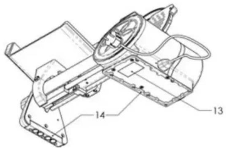
4. COMPONENTES PRINCIPAIS MODELO ICON LINE
natural_image
Technical drawing of a mechanical component with dimension lines D and E (no text or symbols)Cuprins
- REGLEMENTĂRI DE CONFORMITATE 138
- LISTA SEMNELOR ŞI SIMBOLURILOR DE PE UTILAJ ŞI AMBALAJ 138
- DESCRIERE 139
- COMPONENTE PRINCIPALE MODEL LINIE PICTOGRAMĂ 139
- CERINȚE DE SIGURANȚĂ 140
5.1 POZITIA DE SIGURANTĂ 140
- RESPONSABILITATEA PRODUCĂTORULUI 141
- AMBALAREA ŞI DEMONTAREA AMBALAJULUI 141
- INSTALARE 142
8.1 CONDIȚII DE MEDIU 142
- INSTRUCTIUNI DE UTILIZARE 142
- CE SĂ FELIEM ȘI CE SĂ NU FELIEM 142
- CURĂTAREA 143
11.1 PRODUSE PENTRU CURĂȚARE 143
11.2 SIGURANTA ÎNCUIETORII CE 143
- PIESE DETAŞABILE: DEMONTAREA, CURĂȚAREA ȘI ASAMBLAREA 143
12.1 AMORTIZOARE DE PRESIUNE 143
12.2 CAPACUL LAMEI 143
- ÎNTRETINERE 143
- DETECTAREA/DEPANAREA ŞI REPARATIILE DEFECTIUNILOR 144
- ELIMINAREA DISPOZITIVULUI 145
- ASISTENTĂ CLIENTI 145
- GARANTIE SI RĂSPUNDERE 145
- CARACTERISTICILE TEHNICE ALE PRODUSULUI - FISA TEHNICĂ 146
- SCHEMA ELECTRICĂ 147
ICON LINE
https://www.theberkelworld.com
https://www.theberkelworld.com
1. REGLEMENT RI DE CONFORMITATE
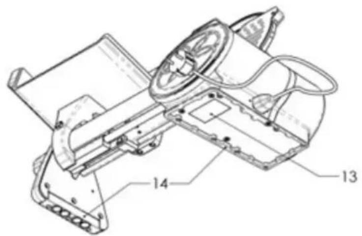
4. COMPONENTE PRINCIPALE MODEL LINIE PICTOGRAM
natural_image
Technical line drawing of a mechanical clamp or bracket component with dimension labels D and E (no text or symbols beyond labels)https://www.theberkelworld.com
2. LISTA ÖVER TECKEN OCH SYMBOLER PÅ MASKIN OCH FÖRPACKNING
MASKINSYMBOLER:
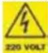
Spänning prisk för
elektrisk stöt

Jordning skydd
https://www.theberkelworld.com

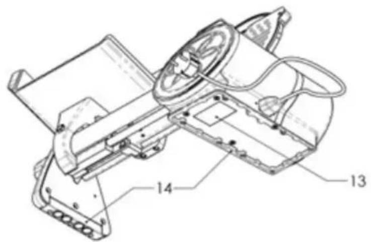
4. HUVUDKOMPONENTER MODELL ICON LINE
natural_image
Technical line drawing of a mechanical component with dimension labels D and E (no text or symbols beyond labels)| ICON LINE 170 | |
| A 140 mm | |
| B 200 mm | |
| C 140 mm | |
| D 326 mm | |
| E 270 mm | |
| F 520 mm | |
| G 455 mm | |
| SPECIFICATIONER | |
| Kapacitet cirkelformad | 140 mm |
| Kapacitet rektangulär skärn | 200x140h mm |
| Maximal skivtjocklek | 0 - 18 mm |
| Klingans diameter | 170 mm |
| Vikt | 10,5 kg |
| Moottorin luokitus 0,19 kW | |
| Elektriska specifikationer 230 V - 50 Hz | |

Van Berkel International S.r.l.
via Ugo Foscolo, 22
21040 Oggiona S. Stefano (VA) - ITALY
T +39 0331 214311
info@berkelinternational.com
theberkelworld.com


- ELECTRIC SLICERS
- Sommario
- ICON LINE
- NORMATIVE DI CONFORMITÀ
- COMPONENTI PRINCIPALI MODELLO ICON LINE
- Index
- COMPLIANCE REGULATIONS
- LIST OF SIGNS AND SYMBOLS ON THE MACHINE AND PACKAGING
- MACHINE SYMBOLS:
- PACKAGING SYMBOLS:
- DESCRIPTION
- Dear Customer,
- MAIN COMPONENTS MODEL ICON LINE
- SAFETY REQUIREMENTS
- WARNING! Risk of elec- tric shock! A damaged
- SAFETY POSITION (Drawing A)
- WARNING! RISK OF CUTTING During clean-
- WARNING! RISK OF ELECTRIC SHOCK! Nev-
- er touch live parts.
- WARNING! S H A R P BLADE, RISK OF CUT-
- TING
- WARNING: Risk of slipping!
- WARNING! The motor may overheat! After 10 tes of continuous use, off the machine and let notor cool down.
- WARNING! Risk of entanglement!
- WARNING! N or m a
- MANUFACTURER'S RESPONSIBILITY
- PACKAGING AND PACKAGING DISPOSAL
- IMPORTANT! It is recommended to keep the original packaging for the entire warranty period to properly pack and transport the device if necessary.
- INSTALLATION
- ENVIRONMENTAL CONDITIONS
- INSTRUCTIONS FOR USE
- WHAT TO SLICE AND WHAT NOT TO SLICE
- WHAT TO SLICE:
- WARNING! Do not attempt to slice prohibit-products!
- CLEANING
- WARNING! Risk of elec- tric shock
- CLEANING PRODUCTS
- CE LOCK SAFETY
- CE Lock Action Procedure:
- REMOVABLE PARTS: REMOVAL, CLEANING, AND ASSEMBLY
- PUSHER
- BLADE COVER
- Important! An undried blade edge can rust.
- MAINTENANCE
- DEVICE DISPOSAL
- CUSTOMER SERVICE
- WARRANTY AND LIABILITY
- Inhaltsverzeichnis
- KONFORMITÄTSVOR- SCHRIFTEN
- HAUPTKOMPONENTEN MODELL ICON LINE
- Sommaire
- NORMES DE CONFORMITÉ
- COMPOSANTS PRINCIPAUX MODÈLE ICON LINE
- Obsah
- HLAVNÍ KOMPONENTY MODEL ICON LINE
- Indholdsfortegnelse
- LISTE OVER TEGN OG SYMBOLER PÅ MASKINE OG EMBALLAGE
- MASKINSYMBOLER:
- Jordforbindelse
- HOVEDKOMPONENTER MODEL ICON LINE
- ADVARSEL! Fare for fastklemning!
- HVAD DER KAN SKÆRES:
- Índice
- LISTA DE SIGNOS Y SÍMBOLOS PRESENTES EN LA MÁQUINA Y EMBALAJE
- Conexión a tierra
- Sisällysluettelo
- KONEEN JA PAKKAUKSEN SYMBOLIT
- KONEEN SYMBOLIT:
- PÄÄKOMPONENTIT MALLI ICON LINE
- Inhoudsopgave
- LIJST VAN TEKENS EN SYMBOLEN OP MACHINE EN VERPAKKING
- HOOFDONDERDELEN MODEL ICON LINE
- Innhold
- LISTE OVER TEGN OG SYMBOLER PÅ MASKIN OG EMBALLASJE
- HOVEDKOMPONENTER MODELL ICON LINE
- Å SKJÆRE PRODUKTER SOM IKKE ER TILLATT!
- RENGJ∅RING
- Sumário
- LISTA DE SINAIS E SÍMBOLOS PRESENTES NA MÁQUINA E NA EMBALAGEM
- SÍMBOLOS NA MÁQUINA:
- COMPONENTES PRINCIPAIS MODELO ICON LINE
- Cuprins
- REGLEMENT RI DE CONFORMITATE
- COMPONENTE PRINCIPALE MODEL LINIE PICTOGRAM
- LISTA ÖVER TECKEN OCH SYMBOLER PÅ MASKIN OCH FÖRPACKNING
- HUVUDKOMPONENTER MODELL ICON LINE
Brand : Berkel
Model : Icon Line 170
Category : Slicer