GKT 13-225 Professional - Saw BOSCH - Free user manual and instructions
Find the device manual for free GKT 13-225 Professional BOSCH in PDF.

User questions about GKT 13-225 Professional BOSCH
0 question about this device. Answer the ones you know or ask your own.
Ask a new question about this device
Download the instructions for your Saw in PDF format for free! Find your manual GKT 13-225 Professional - BOSCH and take your electronic device back in hand. On this page are published all the documents necessary for the use of your device. GKT 13-225 Professional by BOSCH.
USER MANUAL GKT 13-225 Professional BOSCH
| Safety SymbolsThe definitions below describe the level of severity for each signal word. Please read the manual and pay attention to these symbols. | |
 | This is the safety alert symbol. It is used to alert you to potential personal injury hazards. Obey all safety messages that follow this symbol to avoid possible injury or death. |
 | DANGER indicates a hazardous situation which, if not avoided, will result in death or serious injury. |
 | WARNING indicates a hazardous situation which, if not avoided, could result in death or serious injury. |
 | CAUTION indicates a hazardous situation which, if not avoided, could result in minor or moderate injury. |
General Power Tool Safety Warnings
WARNING
Read all safety warnings, instructions, illustrations and specifications provided with this power tool. Failure to follow all instructions listed in electric shock, fire and/or serious injury.
SAVE ALL WARNINGS AND INSTRUCTIONS FOR FUTURE REFERENCE
The term “power tool” in the warnings refers to your mains-operated (corded) power tool or battery-operated (cordless) power tool.
Work area safety
Keep work area clean and well lit.
Cluttered or dark areas invite accidents.
Do not operate power tools in explosive atmospheres, such as in the presence of flammable liquids, gases or dust. Power tools create sparks which may ignite the dust or fumes.
Keep children and bystanders away while operating a power tool. Distractions can cause you to lose control.
Electrical safety
Power tool plugs must match the outlet. Never modify the plug in any way. Do not use any adapter plugs with earthed (grounded) power tools. Unmodified plugs and matching outlets will reduce risk of electric shock.
Avoid body contact with earthed or grounded surfaces, such as pipes, radiators, ranges and refrigerators. There is an increased risk of electric shock if your body is earthed or grounded.
Do not expose power tools to rain or wet conditions. Water entering a power tool will increase the risk of electric shock.
Do not abuse the cord. Never use the cord for carrying, pulling or unplugging the power tool. Keep cord away from heat, oil, sharp edges or moving parts. Damaged or entangled cords increase the risk of electric shock.
When operating a power tool outdoors, use an extension cord suitable for outdoor use. Use of a cord suitable for outdoor use reduces the risk of electric shock.
If operating a power tool in a damp location is unavoidable, use a Ground Fault Circuit Interrupter (GFCI) protected supply. Use of an GFCI reduces the risk of electric shock.
Personal safety
Stay alert, watch what you are doing and use common sense when operating a power tool. Do not use a power tool while you are tired or under the influence of drugs, alcohol or medication. A moment of
General Power Tool Safety Warnings
inattention while operating power tools may result in serious personal injury.
Use personal protective equipment.
Always wear eye protection. Protective equipment such as dust mask, non-skid safety shoes, hard hat, or hearing protection used for appropriate conditions will reduce personal injuries.
Prevent unintentional starting. Ensure the switch is in the off-position before connecting to power source and / or battery pack, picking up or carrying the tool. Carrying power tools with your finger on the switch or energizing power tools that have the switch on invites accidents.
Remove any adjusting key or wrench before turning the power tool on. A wrench or a key left attached to a rotating part of the power tool may result in personal injury.
Do not overreach. Keep proper footing and balance at all times. This enables better control of the power tool in unexpected situations.
Dress properly. Do not wear loose clothing or jewelry. Keep your hair, clothing and gloves away from moving parts. Loose clothes, jewelry or long hair can be caught in moving parts.
If devices are provided for the connection of dust extraction and collection facilities, ensure these are connected and properly used. Use of dust collection can reduce dust-related hazards.
Do not let familiarity gained from frequent use of tools allow you to become complacent and ignore tool safety principles. A careless action can cause severe injury within a fraction of a second.
Power tool use and care
Do not force the power tool. Use the correct power tool for your application.
The correct power tool will do the job better and safer at the rate for which it was designed.
Do not use the power tool if the switch does not turn it on and off. Any power tool that cannot be controlled with the switch is dangerous and must be repaired.
Disconnect the plug from the power source and/or the battery pack from the power tool before making any adjustments, changing accessories, or storing power tools. Such preventive safety measures reduce the risk of starting the power tool accidentally.
Store idle power tools out of the reach of children and do not allow persons unfamiliar with the power tool or these instructions to operate the power tool.
Power tools are dangerous in the hands of untrained users.
Maintain power tools and accessories. Check for misalignment or binding of moving parts, breakage of parts and any other condition that may affect the power tool's operation. If damaged, have the power tool repaired before use. Many accidents are caused by poorly maintained power tools.
Keep cutting tools sharp and clean. Properly maintained cutting tools with sharp cutting edges are less likely to bind and are easier to control.
Use the power tool, accessories and tool bits etc. in accordance with these instructions, taking into account the working conditions and the work to be performed. Use of the power tool for operations different from those intended could result in a hazardous situation.
Keep handles and grasping surfaces dry, clean and free from oil and grease. Slippery handles and grasping surfaces do not allow for safe handling and control of the tool in unexpected situations.
Service
Have your power tool serviced by a qualified repair person using only identical replacement parts. This will ensure that the safety of the power tool is maintained.
Safety Rules for Circular Saws
DANGER
Keep hands away from cutting area and the blade.
Keep your second hand on auxiliary handle, or motor housing. If both hands are holding the saw, they cannot be cut by the blade.
Do not reach underneath the workpiece. The guard cannot protect you from the blade below the workpiece.
Adjust the cutting depth to the thickness of the workpiece. Less than a full tooth of the blade teeth should be visible below the workpiece.
Never hold piece being cut in your hands or across your leg. Secure the workpiece to a stable platform. It is important to support the work properly to minimize body exposure, blade binding, or loss of control.
Hold the power tool by insulated gripping surfaces only, when performing an operation where the cutting tool may contact hidden wiring or its own cord. Contact with a "live" wire will also make exposed metal parts of the power tool "live" and could give the operator an electric shock.
When ripping, always use track, rip fence or straight edge guide. This improves the accuracy of cut and reduces the chance of blade binding.
Always use blades with correct size and shape (diamond versus round) of arbor holes. Blades that do not match the mounting hardware of the saw will run eccentrically, causing loss of control.
Never use damaged or incorrect blade washers or bolt. The blade washers and bolt were specially designed for your saw, for optimum performance and safety of operation.
Inspect the condition and quality of the wood and remove all nails from lumber before cutting. Wet lumber, green lumber or pressure treated lumber require special attention during cutting operation to prevent kickback.
Hold the saw firmly to prevent loss of control. Figures in this manual illustrate typical hand support of the saw.
Depending upon use, the switch may not last the life of the saw. If the switch should fail in the "OFF" position, the saw may not
start. If it should fail while the saw is running, the saw may not shut off. If either occurs, unplug the saw immediately and do not use until repaired.
This circular saw should not be mounted to a table and converted to a table saw.
Circular saws are not designed or intended to be used as table saws.
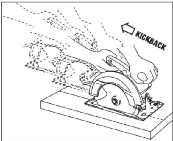
Kickback causes and related warnings
Kickback is a sudden reaction to a pinched, jammed or misaligned saw blade, causing an uncontrolled saw to lift up and out of the workpiece toward the operator.
When the blade is pinched or jammed tightly by the kerf closing down, the blade stalls and the motor reaction drives the unit rapidly back toward the operator.
If the blade becomes twisted or misaligned in the cut, the teeth at the back edge of the blade can dig into the top surface of the wood causing the blade to climb out of the kerf and jump back toward the operator.
Kickback is the result of saw misuse and/or incorrect operating procedures or conditions and can be avoided by taking proper precautions as given below:
Maintain a firm grip with both hands on the saw and position your arms to resist kickback forces. Position your body to either side of the blade, but not in line with the blade. Kickback could cause the saw to jump backwards, but kickback forces can be controlled by the operator, if proper precautions are taken.
When blade is binding, or when interrupting a cut for any reason, release the trigger and hold the saw motionless in the material until the blade comes to a complete stop. Never attempt to remove the saw from the work or pull the saw backward while the blade is in motion or kickback may occur. Investigate and take corrective action to eliminate the cause of blade binding.
When restarting a saw in the workpiece, center the saw blade in the kerf so that the saw teeth are not engaged into the material. If saw blade binds, it may walk up or kickback from the workpiece as the saw is restarted.
Safety Rules for Circular Saws
Support large panels to minimize the risk of blade pinching and kickback. Large panels tend to sag under their own weight. Supports must be placed under the panel on both sides, near the line of cut and near the edge of the panel.
Do not use dull or damaged blades. Unsharpened or improperly set blades produce narrow kerf causing excessive friction, blade binding and kickback.
Blade depth and bevel adjusting locking levers must be tight and secure before making the cut. If blade adjustment shifts while cutting, it may cause binding and kickback.
Use extra caution when sawing into existing walls or other blind areas. The protruding blade may cut objects that can cause kickback.
The blade washers and the bolt on your saw have been designed to work as a clutch to reduce the intensity of a kickback. Understand the operation and settings of the VARI-TORQUE CLUTCH. The proper setting of the clutch, combined with firm handling of the saw will allow you to control kickback.
text_image
KICKBACKNever place your hand behind the saw blade. Kickback could cause the saw to jump backwards over your hand.
Do not use the saw with an excessive depth of cut setting. Too much blade exposure increases the likelihood of the blade twisting in the kerf and increases the surface area of the blade available for pinching that leads to kickback.
Guard function
Check the guard for proper closing before each use. Do not operate the saw if the guard does not move freely and enclose the blade instantly. Never clamp or tie the guard so that the blade is exposed. If the saw is accidentally dropped, the guard may be bent. Check to make sure that the guard moves freely and does not touch the blade or any other part, in all angles and depths of cut.
Check the operation and condition of the guard return spring. If the guard and the spring are not operating properly, they must be serviced before use. The guard may operate sluggishly due to damaged parts, gummy deposits, or a build-up of debris.
Assure that the base plate of the saw will not shift while performing a “plunge cut”. Blade shifting sideways will cause binding and likely kick back.
Always observe that the guard is covering the blade before placing the saw down on bench or floor. An unprotected, coasting blade will cause the saw to walk backwards, cutting whatever is in its path. Be aware of the time it takes for the blade to stop after the switch is released.
Do not run the tool while carrying it at your side. Guard may be opened by a contact with your clothing. Accidental contact with the spinning saw blade could result in serious personal injury.
Periodically clean the guard and the guard spring area with compressed air.
Preventive maintenance and properly operating guard will reduce the probability of an accident.
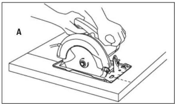
Place the wider portion of the footplate on that part of the workpiece, which is solidly supported, not on the section that will fall
Safety Rules for Circular Saws
off when the cut is made. As examples, Fig. A illustrates the RIGHT way to cut off the end of a board, and Fig. B the WRONG way.
natural_image
Illustration of hands using a cutting tool to cut a circular component on a workbench (no text or symbols)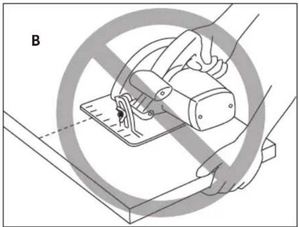
natural_image
Illustration of a hand using a sewing machine to cut a flat surface, with no text or symbols present.If the workpiece is short or small, clamp it down. DO NOT TRY TO HOLD SHORT PIECES BY HAND!
Additional Safety Warnings
GFCI and personal protection devices like electrician's rubber gloves and footwear will further enhance your personal safety.
Do not use AC only rated tools with a DC power supply. While the tool may appear to work, the electrical components of the AC rated tool are likely to fail and create a hazard to the operator.
Keep handles dry, clean and free from oil and grease. Slippery hands cannot safely control the power tool.
Use clamps or another practical way to secure and support the workpiece to a stable platform. Holding the work by hand or against your body leaves it unstable and may lead to loss of control.
Develop a periodic maintenance schedule for your tool. When cleaning a tool be careful not to disassemble any portion of the tool since internal wires may be misplaced or pinched or safety guard return springs may be improperly
mounted. Certain cleaning agents such as gasoline, carbon tetrachloride, ammonia, etc. may damage plastic parts.
Risk of injury to user. The power cord must only be serviced by a Bosch Factory Service Center or Authorized Bosch Service Station.
WARNING Some dust created by power sanding, sawing, grinding, drilling, and other construction activities contains chemicals known to cause cancer, birth defects or other reproductive harm. Some examples of these chemicals are:
- Lead from lead-based paints,
- Crystalline silica from bricks and cement and other masonry products, and
- Arsenic and chromium from chemically-treated lumber.
Your risk from these exposures varies, depending on how often you do this type of work. To reduce your exposure to these chemicals: work in a well ventilated area, and work with approved safety equipment, such as those dust masks that are specially designed to filter out microscopic particles.
Symbols
Important: Some of the following symbols may be used on your tool. Please study them and learn their meaning. Proper interpretation of these symbols will allow you to operate the tool better and safer.
| Symbol Designation / Explanation | |
| V Volts (voltage) | |
| A Amperes (current) | |
| Hz Hertz (frequency, cycles per second) | |
| W Watt (power) | |
| kg Kilograms (weight) | |
| min Minutes (time) | |
| s Seconds (time) | |
| ∅ Diameter (size of drill bits, grinding wheels, etc.) | |
| n_0 | No load speed (rotational speed at no load) |
| n Rated | speed (maximum attainable speed) |
| .../min | Revolutions or reciprocation per minute (revolutions, strokes, surface speed, orbits etc. per minute) |
| 0 Off position (zero speed, zero torque...) | |
| 1, 2, 3, ...I, II, III, | Selector settings (speed, torque or position settings. Higher number means greater speed) |
| 0 | Infinitely variable selector with off (speed is increasing from 0 setting) |
| → | Arrow (action in the direction of arrow) |
| ~ | Alternating current (type or a characteristic of current) |
| --- | Direct current (type or a characteristic of current) |
| ~ | Alternating or direct current (type or a characteristic of current) |
| □ | Class II construction (designates double insulated construction tools) |
| ⊕ | Earthing terminal (grounding terminal) |
Symbols
Important: Some of the following symbols may be used on your tool. Please study them and learn their meaning. Proper interpretation of these symbols will allow you to operate the tool better and safer.
| Symbol Designation / Explanation | |
 | Designates Li-ion battery recycling program |
 | Designates Ni-Cad battery recycling program |
 | Alerts user to read manual |
 | Alerts user to wear eye protection |
 | This symbol designates that this tool is listed by Underwriters Laboratories. |
 | This symbol designates that this component is recognized by Underwriters Laboratories. |
 | This symbol designates that this tool is listed by Underwriters Laboratories, to United States and Canadian Standards. |
 | This symbol designates that this tool is listed by the Canadian Standards Association. |
 | This symbol designates that this tool is listed by the Canadian Standards Association, to United States and Canadian Standards. |
 | This symbol designates that this tool is listed by the Intertek Testing Services, to United States and Canadian Standards. |
 | This symbol designates that this tool complies to NOM Mexican Standards. |
Getting to Know Your Saw
WARNING
Disconnect the plug from the power source before making any assembly, adjustments or changing accessories. Such preventive safety
measures reduce the risk of starting the tool accidentally.
text_image
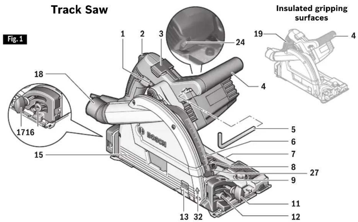
Track Saw Fig. 1 18 1716 15 13 32 19 4 24 Insulated gripping surfaces 5 6 7 8 27 9 11 121 On/Off switch
2 Lock-off button (for On/Off switch)
3 Depth lock lever
4 Auxiliary handle (insulated gripping surface)
5 Hex wrench
6 Cutting-depth scale
7 Footplate (Base plate)
8 Cutting-depth indicator
9 Bevel scale
10 Wing bolt for rip fence**
11 Bevel adjustment knob, front
12 Button for 47° bevel angle
13 Viewing window
14 Rip fence**
15 Blade guard
16 Button for -1^ bevel angle
17 Bevel lock knob, rear
18 Swiveling dust port
19 Handle (insulated gripping surface)
20 Blade stud*
21 Outer washer*
22 Saw blade* **
23 Inner washer*
24 Speed dial
25 Shaft lock button*
26 Blade shaft*
27 Depth stop slider
28 Line guide 0° *
29 Line guide 45° *
30 Plastic insert*
31 Knurled alignment knobs*
32 Direction of rotation arrow
33 Straight edge guide*
34 Vacuum hose * **
35 Front cut limit mark*
36 Rear cut limit mark*
* Not Shown. See further in these operating instructions.
** Sold separately
Specifications
| Model number GKT13-225 | |
| Blade 6-1/2" | |
| Blade arbor hole 20mm Round | |
| Tooth thickness | 0.1" (2.6mm)* *minimum 0.07" (1.8mm) |
| Blade thickness 0.07" (1.8mm) Maximum | |
| Depth of cut at 90° 2-1/4" (57mm) Maximum | |
| Depth of cut at 45° 1.65" (42mm) Maximum | |
| Depth of cut at 47° 1.6" (40.8mm) Maximum | |
NOTE: For tool specifications refer to the nameplate on your tool.
Certified to
CAN/CSA C22.2 No. 62841-2-5-16
UL 62841-2-5 (Ed.1)
in conjunction with
CAN/CSA C22.2 No. 62841-1-15
UL 62841-1 (Ed.1)
Including CSA Initial factory evaluation
Getting to Know Your Track
text_image
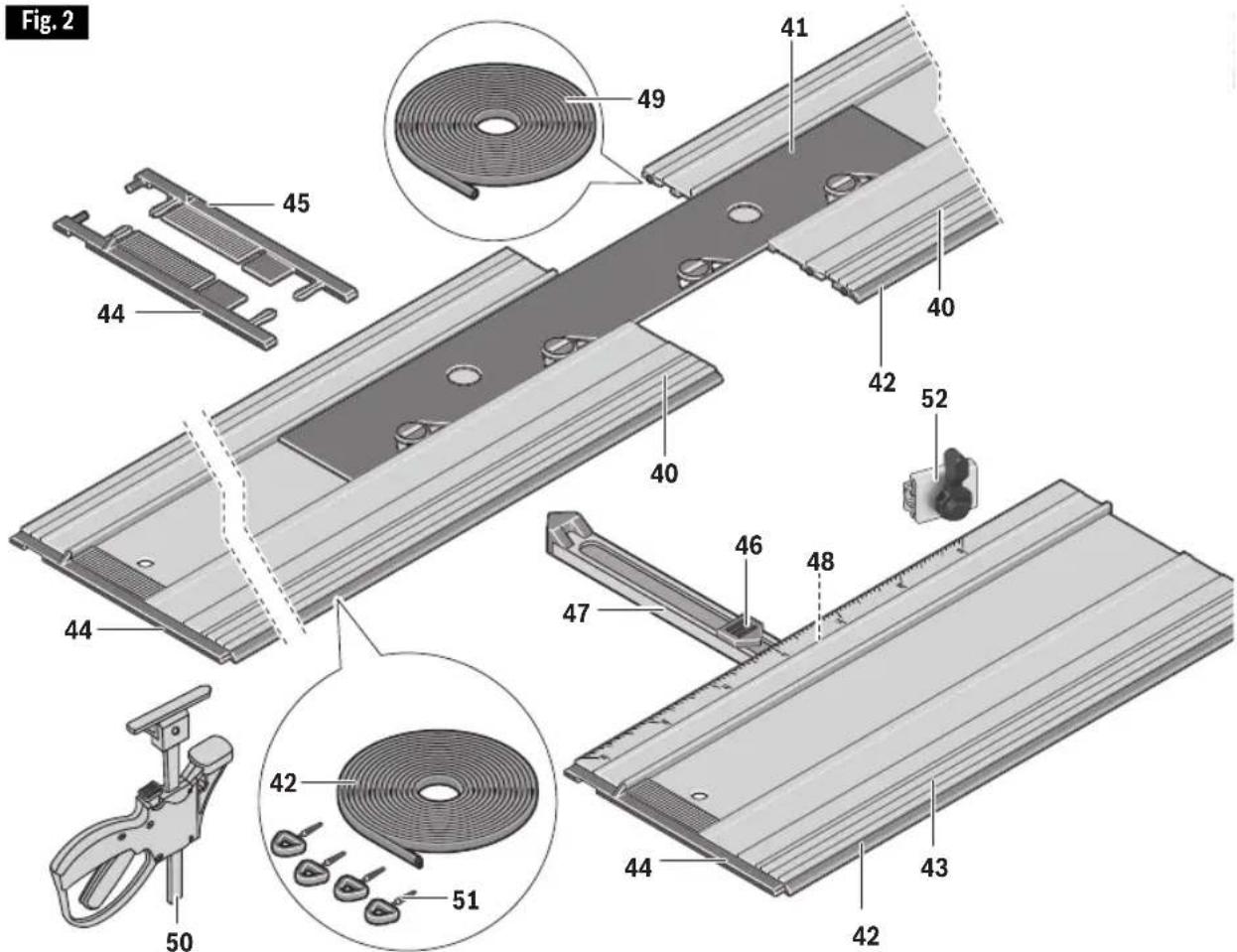
Fig. 2 49 41 45 40 42 52 40 46 48 47 44 43 42 44 45 44 50 42 5140 Track
41 Track Connector
42 Anti-splinter edge
43 Miter guide
44 End cap, left
45 End cap, right
46 Miter angle indicator
47 Fence
48 Miter locking knob
49 Traction strip
50 Track Clamps (x2)
51 Spikes
52 Travel Stop
Saw Assembly
▶ Replacing The Blade

Disconnect the plug from the power source
before making any assembly, adjustments or changing accessories. Such preventive safety measures reduce the risk of starting the tool accidentally.

Use only 6-1/2" blade rated 6250/min (RPM)
or greater. Do not use abrasive wheels. Using blade not designed for the saw may result in serious personal injury and property damage.
Hex wrench 5 is stored in the auxiliary handle (Fig. 1).
▼ REMOVING THE BLADE
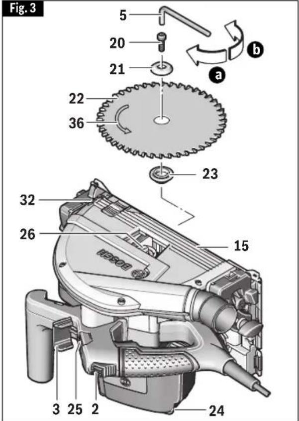
A. Squeeze the depth stop slider 27 and move it all the way down (Fig. 1). For changing the blade, it is best to place the saw on the side of the motor housing (Fig. 3).
B. Pivot lever 3 toward the front (Fig. 3).
C. Push lock-off button 2 toward the front and press the saw toward footplate 7 until it audibly engages in the position for changing the saw blade (the blade stud 20 or the blade shaft 26 is accessible through the window in the blade guard 15).
D. Press and hold the shaft lock button 25.
Note: The shaft lock button 25 may be actuated only when the saw is at a standstill. Otherwise, the saw can be damaged.
E. With the hex wrench 5, loosen the blade stud 20 turning in rotation direction b (counterclockwise).
F. Remove the outer washer 21 and the saw blade 22 from the blade shaft 26.
▼ ATTACHING THE BLADE
G. Make sure the replacement saw blade 22 and washers 21 and 23 are clean. Place the saw blade 22 on to the inner washer 23. Make sure the saw blade teeth and arrow 36 on the blade point in the same direction as the arrow 32 on the blade guard 15.
H. Mount the outer washer 21 and screw
the blade stud 20 into the blade shaft 26 turning in rotation direction a (clockwise). Observe correct mounting position of the mounting flange 23 and clamping flange 21.
I. Press and hold the shaft lock button 25. First tighten blade stud 20 finger tight, then with the hex wrench 5, tighten the blade stud 20 1/8 turn (45°) in rotation direction a (clockwise).
Note: Do not use wrenches with longer handles, since it may lead to over tightening of the blade stud.
J. Pivot the depth lock lever 3 back. When doing this, the saw retracts back to the starting position.
▼ VARI-TORQUE CLUTCH
This clutching action is provided by the friction of the outer washer 21 against the blade 22 and permits the blade shaft 26 to turn when the blade encounters excessive resistance. When the blade stud 20 is properly tightened (as described in step I of "Attaching The
text_image
Fig. 3 5 20 21 a b 22 36 23 32 26 15 3 25 2 24Saw Assembly
Blade"), the blade will slip when it encounters excessive resistance, thus reducing saw's tendency to kickback.
One setting may not be sufficient for cutting all materials. If excessive blade
slippage occurs, tighten the blade stud a fraction of a turn more (less than 1/8 turn). OVERTIGHTENING THE BLADE STUD NULLIFIES THE EFFECTIVENESS OF THE CLUTCH.
Track Assembly
▼ ADAPTING THE FOOT PLATE TO VARIOUS TRACKS
The GKT13-225 is designed specifically for precision straight cutting while using a track for guidance.
The Bosch tracks (sold separately) are available in five sizes:
| FSN800 31.5” (800 mm) |
| FSN1100 43.3” (1100 mm) |
| FSN1600 63” (1600 mm) |
| FSN2100 82.7” (2100 mm) |
▼ PREPARING TRACK
Prior to using a track for the first time, the track's rubber anti-splinter edge 42 must be adapted to the specific saw and blade to be used.
A. Place the complete length of track onto a scrap workpiece that is at least 3/4" (19mm) thick.
B. Secure the tracks as described in "SECURING TRACKS" further.
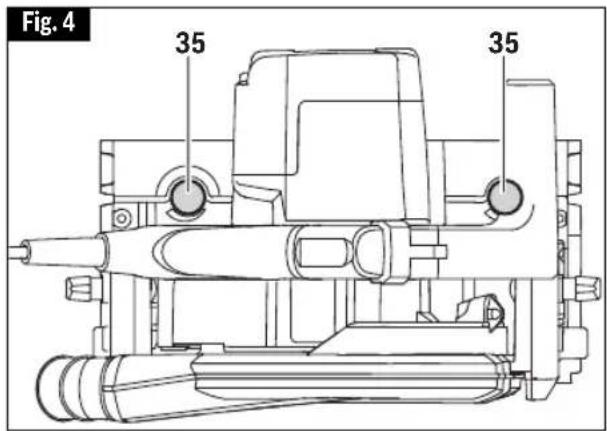
C. Place the saw onto the tracks and adjust the accuracy of its fit using the two knurled alignment knobs 35 (Fig. 4).
- Clockwise rotation of the knobs tightens the fit of the saws footplate on to the track's guiderail
- Counterclockwise rotation of the knobs loosens the fit of the saws footplate on to the track's guiderail.
D. Move cutting-depth indicator 8 to its upper position (See Fig. 21).
E. Make sure that the cutting depth indicator 8 is in position b (Fig. 21)
text_image
Fig. 4 35 35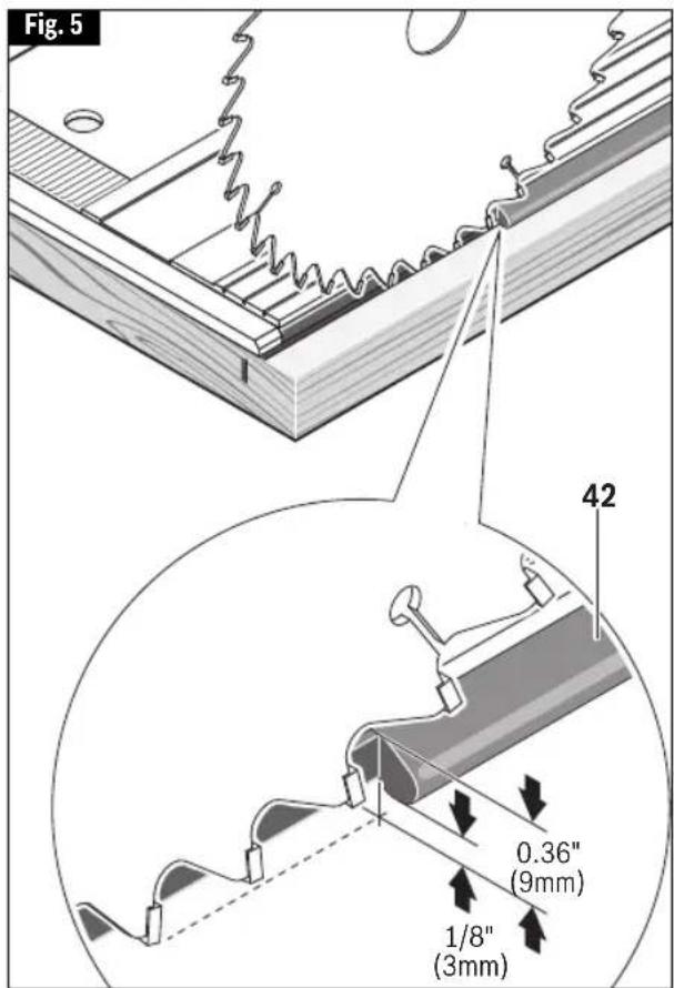
text_image
Fig. 5 42 0.36" (9mm) 1/8" (3mm)Track Assembly
F. Adjust the saw's cutting depth to approximately 0.36" (9 mm) and the bevel angle to 0°. This will result in the blade extending 1/8" (3mm) below the anti-splinter edge.
G. Following the instructions in the "SWITCHIN ON AND OFF" section on page 19, switch on the saw and guide it uniformly with a slow feed rate through the end of the track.
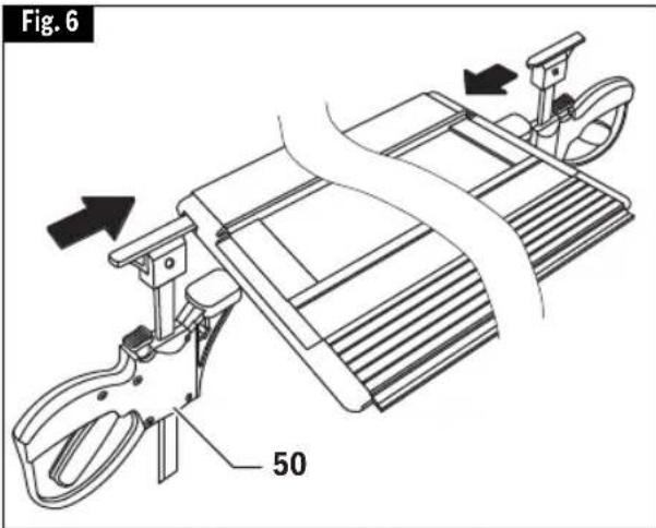
▼ SECURING TRACKS
⚠ WARNING To avoid the risk of injury and/or property damage, only use the track clamps to secure the track.
Once the track has been placed in the desired position, insert a track clamp 50 in from each end of the track, then tighten the clamps against the workpiece (Fig. 6).
▼ PROTECTIVE END CAPS
These caps help to protect the ends of the tracks from damage, such as when dropped on their ends. The left 44 and right 45 caps are NOT interchangeable. If one or both of the end caps become damaged, they should simply be replaced.
▼ CONNECTING MULTIPLE TRACKS
A. Pull out the end caps 44 and 45 from facing ends of the tracks 40 to be connected. Store the end caps in a safe place (Fig. 7).
B. Insert the connector 41 into one of the tracks 40 as shown and then slide another track onto the other end of the connector (Fig. 8).
C. Make sure that the tracks have no gap in between them. Move the connector 41 so that the center mark “ ” is positioned at the joint line. Turn all four locks with a screw driver or a coin to secure the connection (Fig. 9).
text_image
Fig. 6 50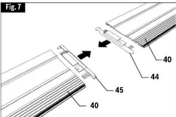
text_image
Fig. 7 40 44 45 40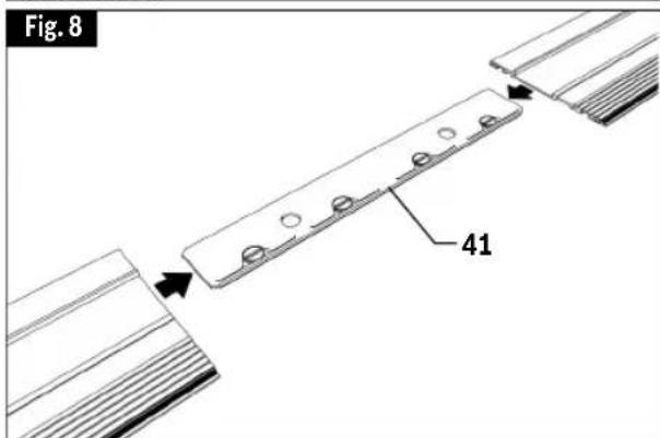
text_image
Fig. 8 41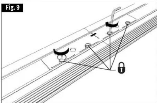
text_image
Fig. 9Track Assembly
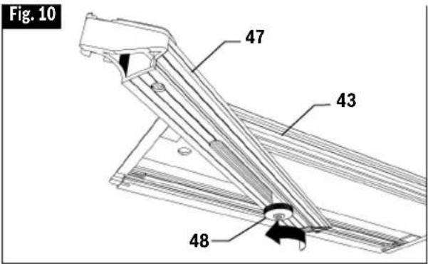
▼ MITER GUIDE
The miter guide 43 (sold separately) can be used to precisely position a track from 60° left to 45° right.
The miter guide must be positioned at the front end of track.
A. Loosen the knob 48 on the bottom of the miter guide (Fig. 10).
B. Follow instructions in "Connecting Multiple Tracks" to attach the miter guide to the desired track using connector 41.
C. Use the fence 47 to set the desired angle. As the fence is moved, the indicator 46 shows the angle (Fig. 11).
D. Once the desired angle is set, tighten the knob 48 on the bottom of the miter guide to hold it at that angle (Fig. 12).
E. Position the fence and connected track such that the fence rests against the workpiece.
F. Once the miter guide and connected track have been positioned as desired, secure the miter guide and connected track in place (refer to "Securing Tracks").
text_image
Fig. 10 47 43 48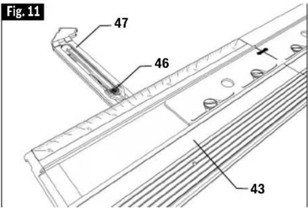
text_image
Fig. 11 47 46 43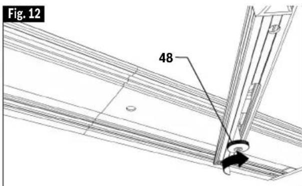
text_image
Fig. 12 48Track Assembly
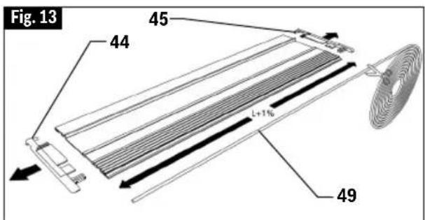
▼ TRACTION STRIPS
It is important that the two rubberlike strips on the bottom of the tracks maintain their ability to minimize the possibility of the track shifting during a cut. If one or both of the strips become worn, they should be replaced. The traction strip roll is 11 feet (3.35m) long.
A. Pull out both end caps 44 and 45 and remove the worn out strips (Fig. 13).
B. Unroll and cut two lengths of traction strip 49 that are 1% longer than the length of the track. E.g. for FSN800 the length of strip should be 80.8cm/31.8" (Fig. 13).
C. Place a light coating of soap on the new strip to make it easier to slide in the grooves on the bottom side of tracks. Pull the strip though the groove to the far end of the track. Cut off the excess strips (Fig. 14).
D. Re-insert both end caps 44 and 45.
▼ TRAVEL STOP FOR TRACK
The travel stop 52 (sold separately) can be used to limit the saw's range of travel (cutting distance) on a track. The stop can be used to help set the starting location of plunge cut or the end point of the cut.
A. Align the track along the intended cut line and clamp into place as described in "Securing Tracks" on page 13.
B. Orient the stop on the track as shown (Fig. 15).
C. Determine the desired start point or end point for the cut.
D. Position the saw such that it will sit in the position where the plunge cut is supposed to start or end.
E. Once the saw placed in the desired location, tighten the stop 52 in place using its lever (Fig. 16).
Move the saw forward to continue the cut until the desired endpoint. When the desired end point is reached, pull the saw's head up, and it will retract to the starting position, and the plunging mechanism becomes locked again.
text_image
Fig. 13 45 44 t+7%o 49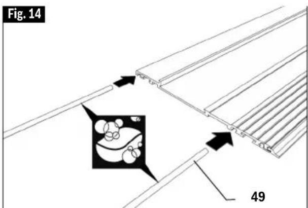
text_image
Fig. 14 49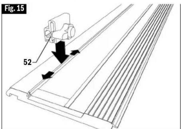
text_image
Fig. 15 52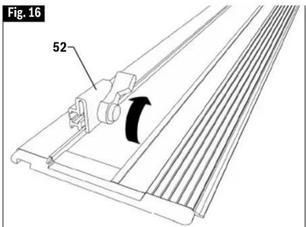
text_image
Fig. 16 52Track Assembly
▼ ANTI-SPLINTER EDGE
To minimize splintering of the workpiece, a worn edge should be replaced. The anti-splinter edge comes in a roll that is 11 feet (3.35m) long and can be cut to size for any given track.
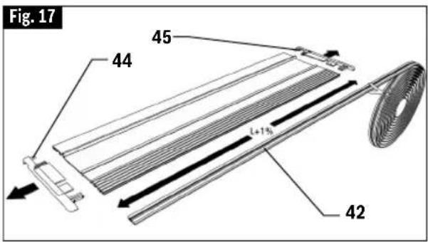
A. Pull out both end caps 44 and 45 and remove the worn out anti-splinter edge. (Fig. 17).
B. Unroll and cut a length of anti-splinter edge 42 that is 1% longer than the length of the track. E.g. for FSN800 the length of strip should be 80.8cm/31.8" (Fig. 17).
C. Place a light coating of soap on the new edge to make it easier to slide in the grooves on the bottom side of track (Fig. 18).
D. Pull the edge though the groove to the far end of the track. Cut off the excess strips. To help prevent the anti-splinter strip from shifting, press one of the spikes 51 into the track alongside the strip at each end. Bend the spike's handle down to break off the handle (Fig. 19).
E. Re-insert the end caps 44 and 45.
F. See "Preparing Track" section on page 12 about adapting the anti-splinter edge to a given saw and blade.
▼ CARRY BAG
The rugged bag accepts two FSN1600 tracks (or shorter) and has a pocket for a Connector and/or a pair of the track quick clamps.
text_image
Fig. 17 45 44 L+1% 42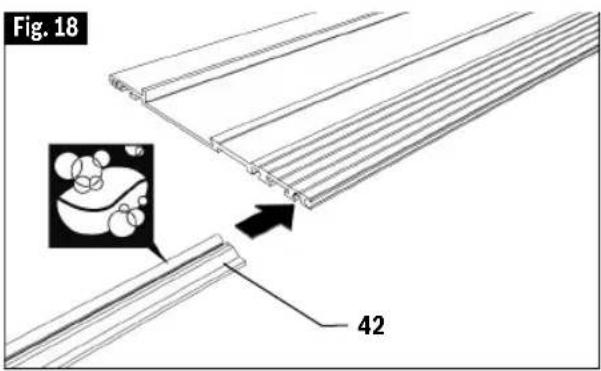
text_image
Fig. 18 42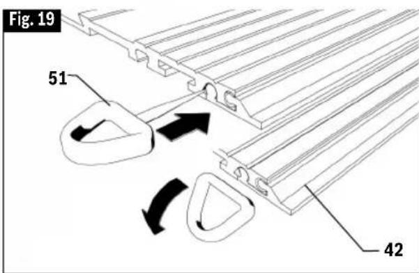
text_image
Fig. 19 51 42Operating Instructions
▶ Depth adjustment
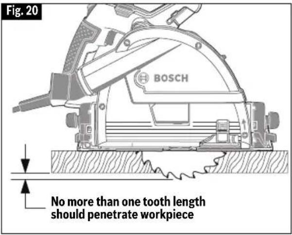
WARNING To reduce the risk of injury, no more than one tooth length of the blade should extend below the material to be cut.
A. Disconnect plug from power source.
B. Turn cutting-depth indicator 8 to the bottom position a for sawing without track, or to the upper position b for sawing with track (Fig. 21).
C. Squeeze the depth-stop slider 27 and move it to the desired depth (material thickness plus one tooth length) on cutting-depth scale 6 (Fig. 22).
Note: Correct depth setting can also reduce splintering.
text_image
Fig. 20 BOSCH No more than one tooth length should penetrate workpiece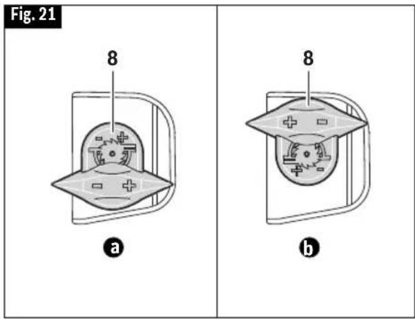
text_image
Fig. 21 8 a 8 b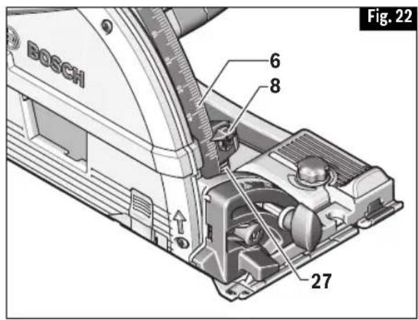
text_image
BOSCH 6 8 27 Fig. 22▶ Bevel Adjustment
WARNING Because of the increased amount of blade engagement in the work and decreased stability of the foot, blade binding may occur. Keep the saw steady and the foot firmly on the workpiece.
- Loosen the knobs 11 and 17. Tilt the saw sideward (Fig 1).
- Adjust the saw to the desired bevel angle on the scale 9. Tighten the knobs 11 and 17 again.
The bevel angle of the saw can be adjusted to -1^ or +47^ .
For the -1^ bevel angle, additionally push button 16 while tilting, or for the +47^ bevel angle, push button 12 while tilting (Fig. 1).
Note: For bevel cuts, the cutting depth is smaller than the setting indicated on the cutting-depth scale 6.
Note: Before making bevel cuts, retract the clear viewing window 13 all the way up.
Operating Instructions
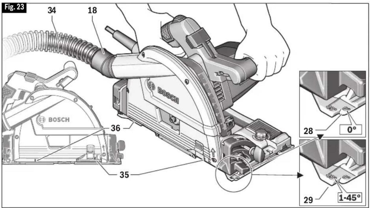
▶ Cutting line guides
The 0° cutting line guide 28 indicates the position of the saw blade for straight cuts whether or not a track is used. When a track is used, it indicates the position of the blade at any bevel angle. The 45° line guide 29 indicates the position of the saw blade for 45° bevel cuts when not using the track (Fig. 23).
- The farthest-back point of a full-depth plunge cut is indicated by the cast-in cut limit mark 36 (Fig. 23).
- The farthest-forward point of a full-depth plunge cut is indicated by the red front cut limit mark 35 on the clear plastic window (Fig. 23).
▶ Dust/Chip Management
The saw's dust port 18 swivels, allowing the dust to exit in the desired direction.
▼ DUST EXTRACTION
The dust port 18 will also accept the typical rubber-like nozzles from 35 mm vacuum cleaner hoses, such as the VX120 that is included with the Bosch VF-Series hoses.
To connect the saw to a 1-1/4" or 1-1/2" hose, the Bosch VAC024 adapter (sold separately) can be used.
Connect the other end of the hose to a suitable dust extractor.
The dust extractor or vacuum cleaner must be suitable for the type of dust that will be created by sawing the workpiece.
text_image
Fig. 23 34 18 BOSCH 36 35 28 0° 29 1-45°Operating Instructions
▶ Basic operations
WARNING
When starting the tool, hold it with both
hands. The torque from the motor can cause the tool to twist.
▼ SPEED SELECTION
The required speed can be preselected with the speed dial 24 before the operation (Fig. 1).
The required speed depends on the saw blade being used and on the material being cut (see overview of saw blades at the end of these operating instructions).
▼ SWITCHING ON AND OFF
To start the machine, first push the lock-off button for the On/Off switch 2 and then press the On/Off switch 1 and keep it pressed.
Actuating lock-off button 2 releases the plunging device at the same time, and allows for the saw to be pushed down. This makes the saw blade plunge into the workpiece. When pulling up, the saw retracts to the starting position and the plunging device is locked again.
To switch off the machine, release the On/Off switch 1.
Note: For safety reasons, the On/Off switch 1 cannot be locked on; it must remain pressed during the entire operation.
Your saw should be running at the desired full speed BEFORE starting the cut, and turned off only AFTER completing the cut. To increase switch life, do not turn switch on and off while cutting.
▼ SOFT START
The soft start feature limits the power consumption when switching the tool on and enables operation from a 13-ampere fuse.
▼ CONSTANT ELECTRONIC CONTROL
Constant electronic control holds the speed constant at no-load and under load, and helps to ensure uniform working performance.
▶ General Cutting Instructions
WARNING
After completing a cut and the trigger has
been released, be aware of the necessary time it takes for the blade to come to a complete stop during coast down. Be aware of the blade exposure.
Always hold the saw handle with one hand and the auxiliary handle or housing with the other.
Ensure workpiece is securely clamped.
Maintain a firm grip and operate the switch with a decisive action. Never force the saw. Use light and continuous pressure.
Always allow the blade to reach the full speed (as set on the speed dial) before the blade contacts the workpiece.
Unless a plunge cut is required, lower the saw blade to the preset depth before moving the saw forward and into the workpiece.
When cutting is interrupted, to resume cutting: squeeze the trigger and allow the blade to reach full speed, re-enter the cut slowly and resume cutting.
When cutting across the grain, the fibers of the wood have a tendency to tear and lift. Advancing the saw slowly minimizes this effect. For a finish cut, a crosscut blade or miter blade is recommended.
text_image
Fig. 24 19 2 4Operating Instructions
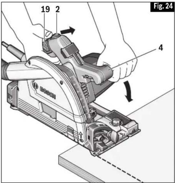
▼ CUTTING WITHOUT PLUNGE ACTION
Hold the tool firmly with both hands (one hand on the main handle 19 and the other on the auxiliary handle 4).
Set the front of footplate on the workpiece to be cut without the blade making any contact (ensure the blade will not make contact with workpiece after it is pushed down to its preset cutting depth).
Push the lock-off button 2 and press the on/off switch 1 to turn the tool on.
Wait until the blade comes to full speed and press down the saw head slowly to the preset depth of cut (Fig. 24).
Push the saw slowly forward over the workpiece surface, keeping it flat and advancing smoothly until the sawing is complete.
At the end of the cut, release on/off switch and wait until the saw blade comes to a complete stop before pulling the saw head up (it will retract to the starting position, and the plunging mechanism becomes locked again.
Note: If the cut did not properly follow your intended cut line, DO NOT attempt to push the saw back to the intended cut line. Doing so may bind the blade and lead to dangerous kickback and possible serious injury. Release on/off
switch, wait for blade to come to a complete stop and then withdraw saw. Realign saw on new cut line, turn tool on and wait for blade come to full speed and then start to cut again.
▶ Working Advice
Protect saw blades against impact and shock.
Guide the machine evenly and with light feed in the cutting direction.
Excessive feed significantly reduces the service life of the saw blade and can cause damage to the saw.
Sawing performance and cutting quality depend essentially on the condition and the tooth profile of the saw blade.
Therefore, use only sharp saw blades that are suited for the material to be cut.
▼ SAWING WOOD
The correct selection of the saw blade depends on the type and quality of the wood and whether lengthway or crossway cuts are required.
When cutting spruce lengthways, long spiral chips are formed.
Beech and oak dusts are especially detrimental to health. Therefore, work only with dust extraction.
text_image
Fig. 25 19 2 4 50 40 40Operating Instructions
▼ SAWING OTHER MATERIALS
The instructions for cutting wood can also be used for cutting structurally stable plastic materials. When cutting plastic materials, always make a test cut to see if the saw causes the material to melt. If necessary, adjust the cutting speed and/or feed rate as necessary to minimize melting.
This saw is not designed to cut metal or masonry.
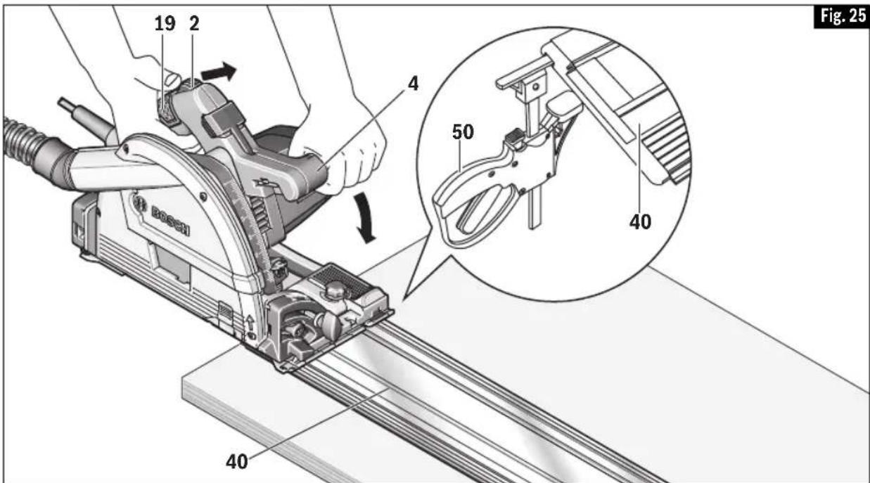
▶ Precision Sawing With Track
The GKT13-225 is designed specifically for precision straight cutting while using a track for guidance (Fig. 25).
- Make sure that track 40 is prepared, positioned and clamped as shown in "Preparing Track" section on page 12.
- Make sure that the saw's footplate is properly placed on track.
• Take extra care when placing saw on portion of a track that extends beyond the leading or ending edge of the workpiece. - When starting a cut in from the leading edges of the workpiece, following instructions in "Plunge Cuts" section below.
- Prior to removing saw from track, raise saw head and retract blade first and allow blade to come to a complete stop.
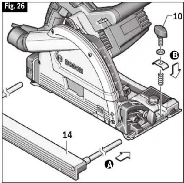
▶ Sawing with Rip Fence
The rip fence 14 (sold separately) enables exact cuts along a workpiece edge and cutting strips of the same dimension.
A. Slide the guide rods of rip fence 14 through the guides in footplate 7.
B. Mount the wing bolt assemblies 10 on both ends as shown, but do not tighten the wing bolt yet (Fig. 26).
C. Adjust the desired cutting width as the scale value at the respective line guides 32 or 33, see section "Cutting Line Guides".
D. Tighten the wing bolts 10.
text_image
Fig. 26 10 B BOSCH 14 A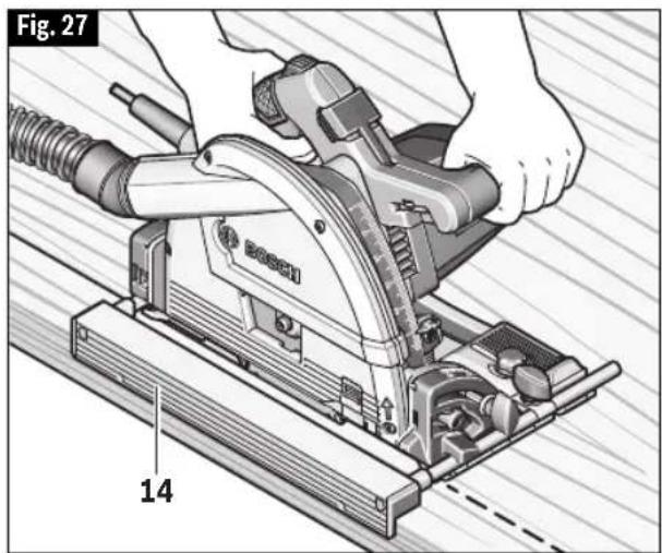
natural_image
Illustration of a person using a Bosch electric plow on a workbench, with no visible text or symbols.Operating Instructions
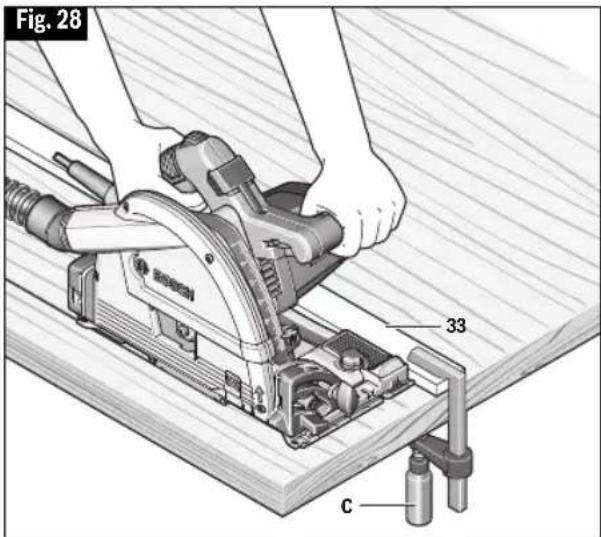
▶ Sawing with Straight Edge Guide
For sawing large workpieces or straight edges, a board or strip can be secured with clamp C (sold separately) to the workpiece as a straight edge guide. The footplate of the circular saw can be guided alongside the straight edge guide 33 (Fig. 28).
- The straight edge guide should be positioned such that the motor side of the saw rides against it when cutting the desired line.
• The deeper the cut, the thinner the straight edge guide must be, because the clearance below the motor along the motor side of the base is very limited. - Ensure that the clamps do not interfere with free movement of the saw.
▶ Cutting Large Sheets
Large sheets and long boards sag or bend, depending on support. If you attempt to cut without leveling and properly supporting the piece, the blade will tend to bind, causing KICK-BACK and extra load on the motor (Fig. 29).
Whether or not a track is being used to make the cut, support the panel or board close to the cut, as shown in Fig. 30. Be sure to set the depth of the cut so that you cut through the sheet or board only and not the table or work bench. The two-by-fours used to raise and support the work should be positioned so that the broadest sides support the work and rest on the table or bench. Do not support the work with the narrow sides as this is an unsteady arrangement. If the sheet or board to be cut is too large for a table or work bench, use the supporting two-by-fours on the floor and secure.
text_image
Fig. 28 33 C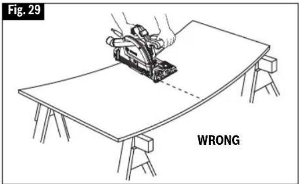
text_image
Fig. 29 WRONG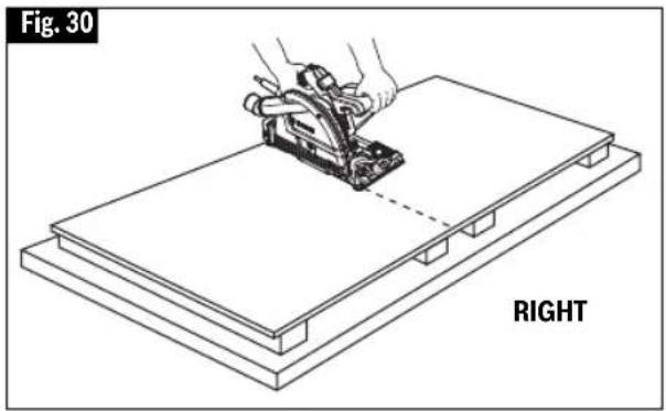
text_image
Fig. 30 RIGHTOperating Instructions
▶ Plunge Cuts
WARNING
Do not perform plunge cut without using
track. Plunge cuts without track increase the risk of injury.
Install track to workpiece to be cut (See "Securing Tracks" section for details).
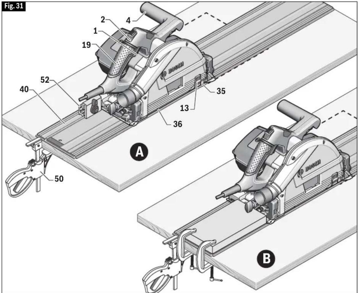
Place the saw on the track 40 at the desired plunge position. Install travel stop 52 (sold separately) on the track with it against the rear edge of the saw footplate (Fig 31, A). As an alternate solution to using the travel stop, fabricate a fixed stop or equivalent that is clamped on the track (Fig 31, B).
Pull the clear window 13 down until it touches the workpiece. Cut limit marks 35 and 36 show the length of plunge cut when the depth of cut is set to
maximum.
Hold the saw firmly with both hands (one hand on the main handle 19 and the other on the auxiliary handle 4).
Push the lock-off button 2 and press the on/off switch 1 to turn the saw on.
Wait until the blade comes to full speed and press down the saw head slowly to the preset depth of cut.
Push the saw slowly forward, keeping the footplate flat against the track and advancing smoothly until the sawing is complete.
At the end of the plunge cut, release on/off switch and wait until the saw blade comes to a complete stop before pulling the saw head up (it will retract to the starting position, and the plunging mechanism becomes locked again).
text_image
Fig. 31 A BMaintenance
WARNING
To avoid accidents always disconnect the tool from the power supply before cleaning or performing any main tenance.
WARNING
Preventive main - tenance performed by unautho rized personnel may result in misplacing of internal wires and components which could cause serious hazard. We recommend that all tool service be performed by a Bosch Factory Service Center or Autho rized Bosch Service Station.
▶ Tool Lubrication
Your Bosch tool has been properly lubricated and is ready to use. It is recommended that tools with gears be regreased with a special gear lubricant at every brush change.
▶ Carbon Brushes
The brushes and commutator in your tool have been engineered for many hours of dependable service. To maintain peak efficiency of the motor, we recommend every two to six months the brush es be examined. Only genuine Bosch replace ment brushes specially designed for your tool should be used.
▶ Bearings
Bearings which become noisy (due to heavy load or very abrasive material cutting) should be replaced at once to avoid overheating or motor failure.
Cleaning
CAUTION
Certain cleaning agents and sol vents damage
plastic parts. Some of these are: gasoline, carbon tetrachloride, chlorinated cleaning solvents, ammonia and house hold detergents that contain ammonia.
Ventilation openings and switch levers must be kept clean and free of foreign matter. Do not attempt to clean by inserting pointed objects through openings.
Care of Blades
Blades become dull even from cutting regular lumber. If you find yourself forcing the saw forward to cut instead of just guiding it through the cut, chances are the blade is dull or coated with wood pitch.
When cleaning gum and wood pitch from blade, unplug the saw and remove the blade. Remember, blades are designed to cut, so handle carefully. Wipe the blade with kerosene or similar sol vent to remove the gum and pitch. Unless you are experienced in sharpening blades, we recommend you do not try.
Extension Cords
WARNING
If an extension cord is necessary, a cord with adequate size conductors that is capable of carrying the current necessary for your tool must be used.
This will prevent excessive voltage drop, loss of power or overheating. Grounded tools must use 3-wire extension cords that have 3-prong plugs and receptacles.
NOTE: The smaller the gauge number, the higher the cord capacity.
RECOMMENDED SIZES OF EXTENSION CORDS 120 VOLT ALTERNATING CURRENT TOOLS
| Tool's Ampere Rating | Cord Size in A.W.G. | Wire Sizes in mm 2 | ||||||
| Cord Length in Feet Cord Length in Meters | ||||||||
| 25 | 50 | 100 | 150 | 15 | 30 | 60 | 120 | |
| 3-6 | 18 | 16 | 16 | 14 | 0.75 | 0.75 | 1.5 | 2.5 |
| 6-8 | 18 | 16 | 14 | 12 | 0.75 | 1.0 | 2.5 | 4.0 |
| 8-10 | 18 | 16 | 14 | 12 | 0.75 | 1.0 | 2.5 | 4.0 |
| 10-12 | 16 | 16 | 14 | 12 | 1.0 | 2.5 | 4.0 | - |
| 12-16 | 14 | 12 | - | - | - | - | - | - |
Attachments and Accessories
WARNING
The use of any other attachments or acces so ries not specified in this manual may create a hazard.
Store accessories in a dry and temperate environment to avoid corrosion and deterioration.
| Bosch No. | Description Included | Sold Separately | |
| Accessories | |||
| PRO648TS | 48-tooth blade for wood and wood composites ● ● | ||
| PRO624TS | 24-tooth blade for wood and wood composites - ● | ||
| Attachments | |||
| FSN... Tracks - ● | |||
| FSNKK Track Clamps - ● | |||
| FSNVEL Track Connector - ● | |||
| FSNWAN Track Miter Guide - ● | |||
| FSNRS Track Travel Stop | - ● | ||
| FSNSS Anti-splinter Edge | - ● | ||
| FSNHB | Traction Strip | - ● | |
| FSNBAG | Carry Bag | - ● | |
| GKTPA Rip Fence | - ● | ||
| VAC024 Vacuum hose adapter for 1-1/4” and 1-1/2” hoses | - ● | ||
| VX120 | Vacuum hose adapter for Bosch VH-series Hoses | - ● | |
Troubleshooting
WARNING
Read instruction manual first! Remove plug from the power source before making adjustments or assembling the blade.
| PROBLEM CAUSE | CORRECTIVE ACTION | |
| Saw will not start 1. | Power cord is not plugged in.2. Power source fuse or circuit breaker tripped.3. Cord damaged.4. Burned out switch.5. Trigger does not turn tool on. | Plug saw in.Replace fuse or reset tripped circuit breaker.Inspect cord for damage. If damaged, have cord replaced by an Authorized Bosch Service Center or Service Station.Have switch replaced by an Authorized Bosch Service Center or Service Station.Disengage lock-off button 2 as described on page 19 |
| Blade does not come up to speed | Extension cord too light or too long.Low house voltage. | Replace with adequate cord.Contact your electric company. |
| Excessive vibration 1. | Blade out of balance.Workpiece not clamped or supported properly. | Discard Blade and use different blade.Clamp or support workpiece as shown on pages 20, 21, 22. |
| Cannot make square cut when crosscutting | Foot plate not adjusted properly. | See “Operating Instructions” section, “Bevel Adjustment” (page 18), “Cutting Line Guides” (page 18), and “Cutting Large Sheets (page 22). |
| Cut binds, burns, stalls motor when ripping | Dull blade with improper tooth set.Warped board.Blade binds.Improper workpiece support. | Discard blade and use a different blade.Make sure concave or hollow side is facing “DOWN” feed slowly, see page 22.Assemble blade and tighten Vari-Torque clutch per “Saw Assembly” instructions. See page 11.Clamp or support workpiece as shown on pages 20, 21, 22. |
| Blade slipping 1. Tool | does not cut workpiece. | Assemble blade and tighten Vari-Torque clutch per “Saw Assembly” instructions. See page 11. |
natural_image
Illustration of hands using a cutting tool on a workbench, no text or symbols present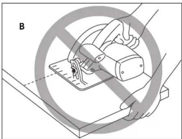
natural_image
Illustration of a hand using a sewing machine to cut a piece of material, with no visible text or symbols.Because of the in creas -
ed amount of blade engagement in the work and decreased stability of the foot, blade binding may occur. Keep the saw steady and the foot firmly on the workpiece.
natural_image
Illustration of a hand using a power tool to cut a saw blade on a workbench, labeled 'Fig. 27' and marked with number 14 (no text or symbols on the diagram itself)natural_image
Line drawing of a hand using a cutting tool to cut a metal sheet (no text or symbols)natural_image
Illustration of a hand operating a sewing machine with a diagonal line indicating no text or symbols (no text or symbols present)CAN/CSA C22.2 No. 62841-2-5-16
UL 62841-2-5 (Ed.1)
en combinación con
CAN/CSA C22.2 No. 62841-1-15
UL 62841-1 (Ed.1)
natural_image
Illustration of a Bosch tool cutting a wooden plow with a 14-unit base (no text or symbols on the diagram itself)This page was intentionally left blank
Robert Bosch Tool Corporation ("Seller") warrants to the original purchaser only, that all BOSCH portable and benchtop power tools will be free from defects in material or workmanship for a period of one year from date of purchase. SELLER'S SOLE OBLIGATION AND YOUR EXCLUSIVE REMEDY under this Limited Warranty and, to the extent permitted by law, any warranty or condition implied by law, shall be the repair or replacement of parts, without charge, which are defective in material or workmanship and which have not been misused, carelessly handled, or misrepaired by persons other than Seller or Authorized Service Station. To make a claim under this Limited Warranty, you must return the complete portable or benchtop power tool product, transportation prepaid, to any BOSCH Factory Service Center or Authorized Service Station. For Authorized BOSCH Power Tool Service Stations, please refer to your phone directory.
THIS LIMITED WARRANTY DOES NOT APPLY TO ACCESSORY ITEMS SUCH AS CIRCULAR SAW BLADES, DRILL BITS, ROUTER BITS, JIGSAW BLADES, SANDING BELTS, GRINDING WHEELS AND OTHER RELATED ITEMS.
ANY IMPLIED WARRANTIES SHALL BE LIMITED IN DURATION TO ONE YEAR FROM DATE OF PURCHASE. SOME STATES IN THE U.S., SOME CANADIAN PROVINCES DO NOT ALLOW LIMITATIONS ON HOW LONG AN IMPLIED WARRANTY LASTS, SO THE ABOVE LIMITATION MAY NOT APPLY TO YOU.
IN NO EVENT SHALL SELLER BE LIABLE FOR ANY INCIDENTAL OR CONSEQUENTIAL DAMAGES (INCLUDING BUT NOT LIMITED TO LIABILITY FOR LOSS OF PROFITS) ARISING FROM THE SALE OR USE OF THIS PRODUCT. SOME STATES IN THE U.S. AND SOME CANADIAN PROVINCES DO NOT ALLOW THE EXCLUSION OR LIMITATION OF INCIDENTAL OR CONSEQUENTIAL DAMAGES, SO THE ABOVE LIMITATION OR EXCLUSION MAY NOT APPLY TO YOU.
THIS LIMITED WARRANTY GIVES YOU SPECIFIC LEGAL RIGHTS, AND YOU MAY ALSO HAVE OTHER RIGHTS WHICH VARY FROM STATE TO STATE IN THE U.S., PROVINCE TO PROVINCE IN CANADA AND FROM COUNTRY TO COUNTRY.
THIS LIMITED WARRANTY APPLIES ONLY TO PORTABLE AND BENCHTOP ELECTRIC TOOLS SOLD WITHIN THE UNITED STATES OF AMERICA, CANADA AND THE COMMONWEALTH OF PUERTO RICO. FOR WARRANTY COVERAGE WITHIN OTHER COUNTRIES, CONTACT YOUR LOCAL BOSCH DEALER OR IMPORTER.
GARANTIE LIMITÉE DES OUTILS ÉLECTRIQUES PORTATIFS ET D'ÉTABLI BOSCH
© Robert Bosch Tool Corporation 1800 W. Central Road Mt. Prospect, IL 60056-2230
Exportado por: Robert Bosch Tool Corporation Mt. Prospect, IL 60056-2230, E.U.A.
text_image
Black and white barcode image with vertical lines and a central dot2610051844