GCO15-14 Professional - Saw BOSCH - Free user manual and instructions
Find the device manual for free GCO15-14 Professional BOSCH in PDF.

User questions about GCO15-14 Professional BOSCH
0 question about this device. Answer the ones you know or ask your own.
Ask a new question about this device
Download the instructions for your Saw in PDF format for free! Find your manual GCO15-14 Professional - BOSCH and take your electronic device back in hand. On this page are published all the documents necessary for the use of your device. GCO15-14 Professional by BOSCH.
USER MANUAL GCO15-14 Professional BOSCH
IMPORTANT Read Before Using
IMPORTANT Lire avant usage
IMPORTANTE Leer antes de usar

natural_image
Icon of a person reading a book inside a circle (no text or symbols)Operating / Safety Instructions Consignes d'utilisation / de sécurité Instrucciones de funcionamiento y seguridad
GCO15-14
natural_image
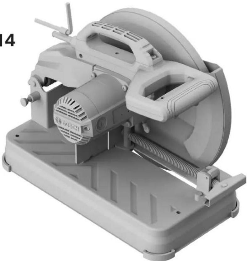
3D rendering of a Bosch electric shaver machine with visible cooling fan and mounting base (no text or symbols)
BOSCH
Call Toll Free for Consumer Information & Service Locations
For English Version See page 2
| The definitions below describe the level of severity for each signal word.Please read the manual and pay attention to these symbols. | |
 | This is the safety alert symbol. It is used to alert you to potential personal injury hazards. Obey all safety messages that follow this symbol to avoid possible injury or death. |
 | DANGER indicates a hazardous situation which, if not avoided, will result in death or serious injury. |
 | WARNING indicates a hazardous situation which, if not avoided, could result in death or serious injury. |
 | CAUTION indicates a hazardous situation which, if not avoided, could result in minor or moderate injury. |
Table of Contents
Safety Symbols 2
General Power Tool Safety Warnings ..... 3
Safety Instructions for Cut-Off Machines ..... 4
Additional Safety Rules 6
Intended Use 6
Specifications 7
Cutting Capacities 7
Double Insulated Tools 8
Polarized Plugs 8
Extension Cords.... 8
Symbols 9
Getting to Know Your GCO15-14 Abrasive Cut-Off Machine 10
Unpacking and Checking Contents ..... 11
Unpacking the Abrasive Cut-Off Machine . . . 11
Checking Contents in Package ..... 11
Assembly 12
Removing the Cut-Off Wheel 12
Installing the 14" (355 mm) Cut-Off Wheel 12
Adjustments.... 13
Using the Head Assembly Lock Pin ..... 13
Lifting Saw with Carry Handle ..... 14
Using the Adjustable Spark Guard ..... 14
Transporting and Mounting 14
Mounting Applications 15
Preparing for Saw Operations 16
Switch Activation 16
Long Workpiece Support ..... 16
Using the Vise Stop 17
Clamping and Releasing the Workpiece .... 17
Preparing for Saw Operations 17
Saw Operations 18
Making a Cut 18
Maintenance and Lubrication 19
Service.... 19
Power Cord 19
Care of Abrasive Wheels.... 19
Tool Lubrication.... 19
Motor Brushes 19
Motor Brush Replacement ..... 19
Bearings.... 19
Cleaning 20
Troubleshooting.... 21
Attachments and Accessories 21
General Power Tool Safety Warnings
WARNING Read all safety warnings, instructions, illustrations and specifications provided with this power tool. Failure to follow all instructions listed below may result in electric shock, fire and/or serious injury.
SAVE ALL WARNINGS AND INSTRUCTIONS FOR FUTURE REFERENCE.
The term “power tool” in the warnings refers to your mains-operated (corded) power tool or BATTERY operated (cordless) power tool.
1. Work area safety
a. Keep work area clean and well lit. Cluttered or dark areas invite accidents.
b. Do not operate power tools in explosive atmospheres, such as in the presence of flammable liquids, gases or dust. Power tools create sparks which may ignite the dust or fumes.
c. Keep children and bystanders away while operating a power tool. Distractions can cause you to lose control.
2. Electrical safety
a. Power tool plugs must match the outlet. Never modify the plug in any way. Do not use any adapter plugs with earthed (grounded) power tools. Unmodified plugs and matching outlets will reduce risk of electric shock.
b. Avoid body contact with earthed or grounded surfaces, such as pipes, radiators, ranges and refrigerators. There is an increased risk of electric shock if your body is earthed or grounded.
c. Do not expose power tools to rain or wet conditions. Water entering a power tool will increase the risk of electric shock.
d. Do not abuse the cord. Never use the cord for carrying, pulling or unplugging the power tool. Keep cord away from heat, oil, sharp edges or moving parts. Damaged or entangled cords increase the risk of electric shock.
e. When operating a power tool outdoors, use an extension cord suitable for outdoor use.
Use of a cord suitable for outdoor use reduces the risk of electric shock.
f. If operating a power tool in a damp location is unavoidable, use a Ground Fault Circuit Interrupter (GFCI) protected supply. Use of a GFCI reduces the risk of electric shock.
3. Personal safety
a. Stay alert, watch what you are doing and use common sense when operating a power tool.
Do not use a power tool while you are tired or under the influence of drugs, alcohol or medication. A moment of inattention while operating power tools may result in serious personal injury.
b. Use personal protective equipment. Always wear eye protection. Protective equipment such as a dust mask, non-skid safety shoes, hard hat or hearing protection used for appropriate conditions will reduce personal injuries.
c. Prevent unintentional starting. Ensure the switch is in the off-position before connecting to power source and/or battery pack, picking up or carrying the tool. Carrying power tools with your finger on the switch or energizing power tools that have the switch on invites accidents.
d. Remove any adjusting key or wrench before turning the power tool on. A wrench or a key left attached to a rotating part of the power tool may result in personal injury.
e. Do not overreach. Keep proper footing and balance at all times. This enables better control of the power tool in unexpected situations.
f. Dress properly. Do not wear loose clothing or jewelry. Keep your hair and clothing away from moving parts. Loose clothes, jewelry or long hair can be caught in moving parts.
g. If devices are provided for the connection of dust extraction and collection facilities, ensure these are connected and properly used. Use of dust collection can reduce dust-related hazards.
h. Do not let familiarity gained from frequent use of tools allow you to become complacent and ignore tool safety principles. A careless action can cause severe injury within a fraction of a second.
4. Power tool use and care
a. Do not force the power tool. Use the correct power tool for your application. The correct power tool will do the job better and safer at the rate for which it was designed.
General Power Tool Safety Warnings
b. Do not use the power tool if the switch does not turn it on and off. Any power tool that cannot be controlled with the switch is dangerous and must be repaired.
c. Disconnect the plug from the power source and/or remove the battery pack, if detachable, from the power tool before making any adjustments, changing accessories, or storing power tools. Such preventive safety measures reduce the risk of starting the power tool accidentally.
d. Store idle power tools out of the reach of children and do not allow persons unfamiliar with the power tool or these instructions to operate the power tool. Power tools are dangerous in the hands of untrained users.
e. Maintain power tools and accessories. Check for misalignment or binding of moving parts, breakage of parts and any other condition that may affect the power tool's operation. If damaged, have the power tool repaired before use. Many accidents are caused by poorly maintained power tools.
f. Keep cutting tools sharp and clean. Properly maintained cutting tools with sharp cutting edges are less likely to bind and are easier to control.
g. Use the power tool, accessories and tool bits etc. in accordance with these instructions, taking into account the working conditions and the work to be performed. Use of the power tool for operations different from those intended could result in a hazardous situation.
h. Keep handles and grasping surfaces dry, clean and free from oil and grease. Slippery handles and grasping surfaces do not allow for safe handling and control of the tool in unexpected situations.
5. Service
a. Have your power tool serviced by a qualified repair person using only identical replacement parts. This will ensure that the safety of the power tool is maintained.
Safety Instructions for Cut-Off Machines
1. Cut-off machine safety warnings
a. Position yourself and bystanders away from the plane of the rotating wheel. The guard helps to protect the operator from broken wheel fragments and accidental contact with wheel.
b. Use only bonded reinforced cut-off wheels for your power tool. Just because an accessory can be attached to your power tool, it does not assure safe operation.
c. The rated speed of the accessory must be at least equal to the maximum speed marked on the power tool. Accessories running faster than their rated speed can break and fly apart.
d. Wheels must be used only for recommended applications. For example: do not grind with the side of a cut-off wheel. Abrasive cut-off wheels are intended for peripheral grinding, side forces applied to these wheels may cause them to shatter.
e. Always use undamaged wheel flanges that are of correct diameter for your selected wheel. Proper wheel flanges support the
wheel thus reducing the possibility of wheel breakage.
f. The outside diameter and the thickness of your accessory must be within the capacity rating of your power tool. Incorrectly sized accessories cannot be adequately guarded or controlled.
g. The arbor size of wheels and flanges must properly fit the spindle of the power tool. Wheels and flanges with arbor holes that do not match the mounting hardware of the power tool will run out of balance, vibrate excessively and may cause loss of control.
h. Do not use damaged wheels. Before each use, inspect the wheels for chips and cracks. If the power tool or wheel is dropped, inspect for damage or install an undamaged wheel. After inspecting and installing the wheel, position yourself and bystanders away from the plane of the rotating wheel and run the power tool at maximum no load speed for one minute. Damaged wheels will normally break apart during this test time.
i. Wear personal protective equipment. Depending on application, use face shield,
Safety Instructions for Cut-Off Machines
safety goggles or safety glasses. As appropriate, wear dust mask, hearing protectors, gloves and shop apron capable of stopping small abrasive or workpiece fragments. The eye protection must be capable of stopping flying debris generated by various operations. The dust mask or respirator must be capable of filtrating particles generated by your operation. Prolonged exposure to high intensity noise may cause hearing loss.
j. Keep bystanders a safe distance away from work area. Anyone entering the work area must wear personal protective equipment.
Fragments of workpiece or of a broken wheel may fly away and cause injury beyond immediate area of operation.
k. Position the cord clear of the spinning accessory. If you lose control, the cord may be cut or snagged and your hand or arm may be pulled into the spinning wheel.
I. Regularly clean the power tool's air vents. The motor's fan can draw the dust inside the housing and excessive accumulation of powdered metal may cause electrical hazards.
m. Do not operate the power tool near flammable materials. Do not operate the power tool while placed on a combustible surface such as wood. Sparks could ignite these materials.
n. Do not use accessories that require liquid coolants. Using water or other liquid coolants may result in electrocution or shock.
2. Kickback and related warnings
Kickback is a sudden reaction to a pinched or snagged rotating wheel. Pinching or snagging causes rapid stalling of the rotating wheel which in turn causes the uncontrolled cutting unit to be forced upwards toward the operator.
For example, if an abrasive wheel is snagged or pinched by the workpiece, the edge of the wheel that is entering into the pinch point can dig into the surface of the material causing the wheel to climb out or kick out. Abrasive wheels may also break under these conditions.
Kickback is the result of power tool misuse and/or incorrect operating procedures or conditions and can be avoided by taking proper precautions as given below.
a. Maintain a firm grip on the power tool and position your body and arm to allow you to resist kickback forces. The operator can con-
trol upward kickback forces, if proper precautions are taken.
b. Do not position your body in line with the rotating wheel. If kickback occurs, it will propel the cutting unit upwards toward the operator.
c. Do not attach a saw chain, woodcarving blade, segmented diamond wheel with a peripheral gap greater than 10 mm or toothed saw blade. Such blades create frequent kickback and loss of control.
d. Do not "jam" the wheel or apply excessive pressure. Do not attempt to make an excessive depth of cut. Overstressing the wheel increases the loading and susceptibility to twisting or binding of the wheel in the cut and the possibility of kickback or wheel breakage.
e. When the wheel is binding or when interrupting a cut for any reason, switch off the power tool and hold the cutting unit motionless until the wheel comes to a complete stop. Never attempt to remove the wheel from the cut while the wheel is in motion otherwise kickback may occur. Investigate and take corrective action to eliminate the cause of wheel binding.
f. Do not restart the cutting operation in the workpiece. Let the wheel reach full speed and carefully re-enter the cut. The wheel may bind, walk up or kickback if the power tool is restarted in the workpiece.
g. Support any oversized workpiece to minimize the risk of wheel pinching and kickback.
Large workpieces tend to sag under their own weight. Supports must be placed under the workpiece near the line of cut and near the edge of the workpiece on both sides of the wheel.
Additional Safety Rules
THINK SAFETY
GFCI and personal protection devices like electrician's rubber gloves and footwear will further enhance your personal safety.
Do not use AC only rated tools with a DC power supply. While the tool may appear to work, the electrical components of the AC rated tool are likely to fail and create a hazard to the operator.
Develop a periodic maintenance schedule for your tool. When cleaning a tool be careful not to disassemble any portion of the tool since internal wires may be misplaced or pinched or safety guard return springs may be improperly mounted. Certain cleaning agents such as gasoline, carbon tetrachloride, ammonia, etc. may damage plastic parts.
Do not use vacuum or other dust collection system when cutting metal. Sparks from metal cutting can cause fire in the collector

The operation of any power tool can result in foreign objects being thrown into the eyes, which can result in severe eye damage.
Always wear safety goggles that comply with ANSI Z87.1 (shown
on pack age) before commencing power tool operation.
WARNING Some dust created by power sanding, sawing, grinding, drilling, and other construction activities contains chemicals known to cause cancer, birth defects or other reproductive harm. Some examples of these chemicals are:
- Lead from lead-based paints,
- Crystalline silica from bricks and cement and other masonry products, and
- Arsenic and chromium from chemically-treated lumber.
Your risk from these exposures varies, depending on how often you do this type of work. To reduce your exposure to these chemicals: work in a well ventilated area, and work with approved safety equipment, such as those dust masks that are specially designed to filter out microscopic particles.
Intended Use
WARNING
Use this abrasive cut-off machine only as intended. Unintended use may result in personal injury and property damage.
This abrasive cut-off machine is designed for the cutting of various shapes of ferrous materials. It is designed only for use with 14-inch (355 mm) reinforced bonded abrasive wheels.
Do not use this abrasive cut-off machine for cutting wood, plastic or any masonry or cement materials with or without water.
Do not use circular saw blades or any other toothed blade with this saw.
Use only abrasive wheels that are reinforced and rated at 4100 rpm or higher.
Specifications
GCO15-14 Abrasive Cut-Off Machine
| Model number GCO15-14 | |
| Voltage 120V~ 60 Hz | |
| Amperage 15A | |
| No Load Speed 4100/min (RPM) | |
| Wheel Diameter ∅ 14" (355 mm) | |
| Wheel Thickness 1/8" (3 mm) | |
| Arbor ∅ 1" (25.4 mm) | |
Cutting Capacities
WARNING
Use of this tool beyond recommended cutting capacities may lead to motor burn-out and possible electric shock.
| Material Maximum Size | |
| Round Material Capacity at 0° 5-3/32" (129 mm) | |
| Round Material Capacity at 45° 5-1/32" (128 mm) | |
| Maximum Wall Thickness 1/4" (6.35 mm) | |
| Workpiece Shape Material/Miter Angle Maximum Height x Width | ||
 | Rectangle Material Capacity at 0° 3-1 | 5/16" x 7-7/8" (100 x 200 mm) |
| Rectangle Material Capacity at 45° | 4-7/32" x 4-17/32" (107 x 115 mm) | |
 | Square Material Capacity at 0° | 4-23/32" x 4-23/32" (120 x 120 mm) |
| Square Material Capacity at 45° | 4-11/32" x 4-11/32" (110 x 110 mm) | |
 | L-Profile Material Capacity at 0° | 5-3/8" x 5-3/8" (137 x 137 mm) |
| L-Profile Material Capacity at 45° | 4-17/32" x 4-17/32" (115 x 115 mm) | |
Double Insulated Tools
Double insulation ☐ is a design concept used in electric power tools which eliminates the need for the three wire grounded power cord and grounded power supply system. It is a recognized and approved system by Underwriter's Laboratories, CSA and Federal OSHA authorities.
IMPORTANT: Servicing of a tool with double insulation requires care and knowledge of the system and should be performed only by a qualified service technician.
WHEN SERVICING, USE ONLY IDENTICAL REPLACEMENT PARTS.
Polarized Plugs
To reduce the risk of electrical shock, your tool is equipped with a polarized plug (one blade is wider than the other), this plug will fit in a polarized outlet only one way. If the plug does not fit fully if the outlet, reverse the plug. If it still does not fit, contact a qualified electrician to install the proper outlet. To reduce the risk of electrical shock, do not change the plug in any way.
Extension Cords
Replace damaged cords immediately. Use of damaged cords can shock, burn or electrocute.
If an extension cord is necessary, a cord with adequate size conductors should be used to prevent excessive voltage drop, loss of power or overheating. The table shows the correct size to use, depending on cord length and nameplate amperage rating of tool. If in doubt, use the next heavier gauge. Always use U.L. and CSA listed extension cords.
RECOMMENDED SIZES OF EXTENSION CORDS 120 VOLT ALTERNATING CURRENT TOOLS
| Tool's Ampere Rating | Cord Size in A.W.G. Wire Sizes in mm ^2 | |||||||
| Cord Length in Feet Cord Length in Meters | ||||||||
| 25 | 50 | 100 | 150 | 15 | 30 | 60 | 120 | |
| 3-6 | 18 | 16 | 16 | 14 | 0.75 | 0.75 | 1.5 | 2.5 |
| 6-8 | 18 | 16 | 14 | 12 | 0.75 | 1.0 | 2.5 | 4.0 |
| 8-10 | 18 | 16 | 14 | 12 | 0.75 | 1.0 | 2.5 | 4.0 |
| 10-12 | 16 | 16 | 14 | 12 | 1.0 | 2.5 | 4.0 | - |
| 12-16 | 14 | 12 | - | - | - | - | - | - |
NOTE: The smaller the gauge number, the higher in the cord capacity.
Symbols
IMPORTANT: Some of the following symbols may be used on your tool. Please study them and learn their meaning. Proper interpretation of these symbols will allow you to operate the tool better and safer.
| Symbol Designation/Explanation | |
| V Volts (voltage) | |
| A Amperes (current) | |
| Hz Hertz (frequency, cycles per second) | |
| W Watt (power) | |
| kg Kilograms (weight) | |
| min Minutes (time) | |
| s Seconds (time) | |
| ∅ Diameter (size of drill bits, grinding wheels, etc.) | |
| n_0 | No load speed (rotational speed, at no load) |
| n Rated | speed (maximum attainable speed) |
| .../min | Revolutions or reciprocation per minute (revolutions, strokes, surface speed, orbits etc. per minute) |
 | Arrow (action in the direction of arrow) |
 | Alternating current (type or a characteristic of current) |
 | Class II construction (designates Double Insulated Construction tools) |
 | Alerts user to read manual. |
 | Alerts user to wear eye protection. |
 | This symbol designates that this tool is listed by Underwriters Laboratories, to United States and Canadian Standards. |
Getting to Know Your GCO15-14 Abrasive Cut-Off Machine
Fig. 1
text_image
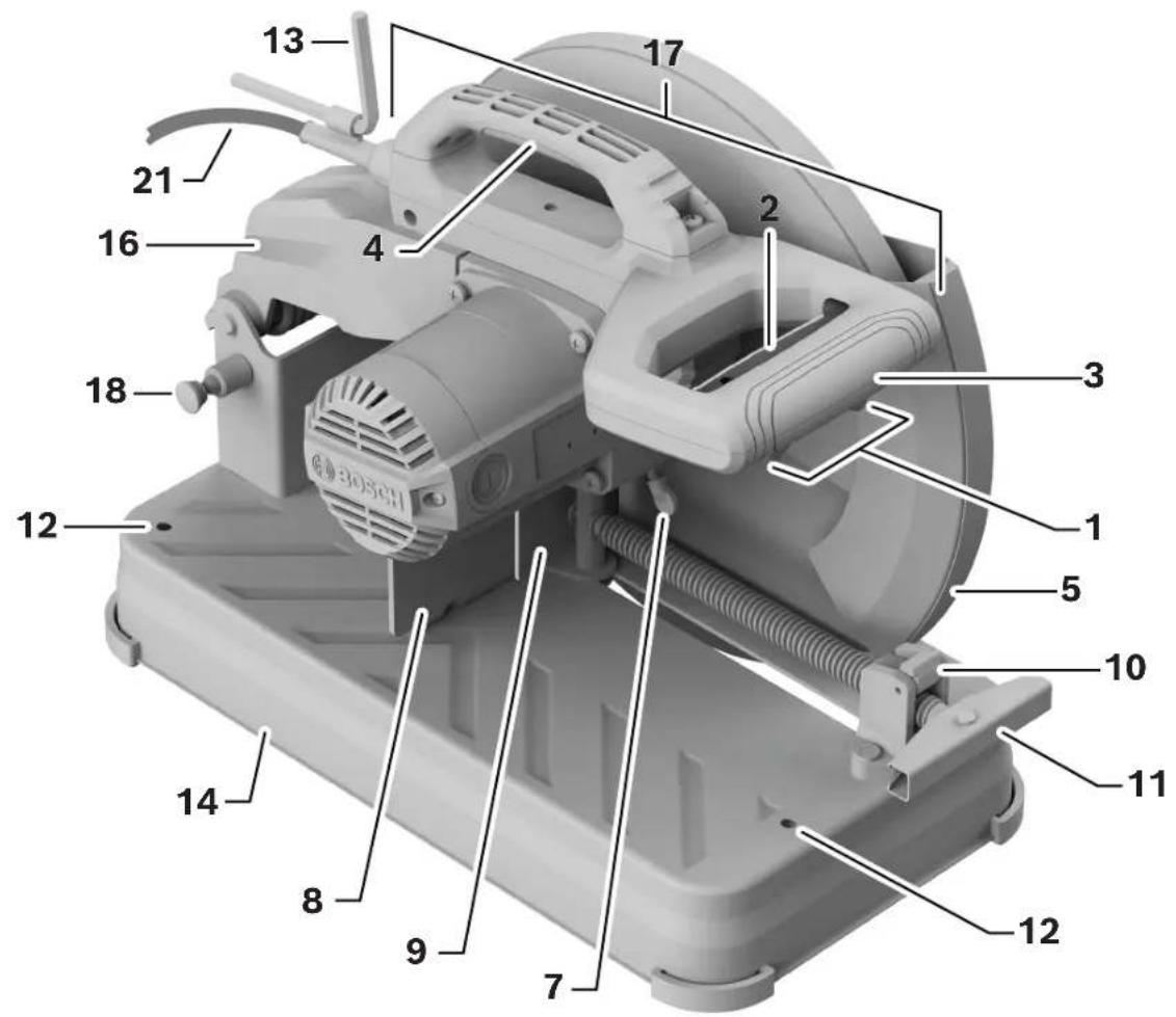
1 2 3 4 5 6 7 8 9 10 11 12 13 14 16 17 18 21 BOSCH1 Switch Lock-Off Release Button – This button must be pressed before the power switch can be pressed.
2 Power Switch - The power switch used with the "Lock-OFF" button energizes the unit.
3 Main Handle – This handle contains the power switch. Pulling this handle down lowers the abrasive wheel into the work piece.
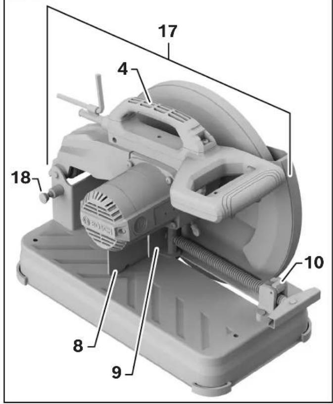
4 Carry Handle - Used to transport the saw.
5 Lower Wheel Guard/Lower Guard Lip – The Lower Wheel Guard helps protect your hands from the spinning wheel. It retracts as the lip makes contact with the workpiece. Lip can be used to raise the lower guard in the event that the guard becomes jammed on a workpiece.
6 Cut-Off Wheel - Use only 14" (355 mm) diameter abrasive wheels with 1" (25.4 mm) diameter arbor holes.
7 Spindle Lock – Locks spindle and prevents rotation during wheel removal and installation.
8 Vise Stop - Swivels 0^ to 45^ to allow for angled miter cuts.
9 Vise Clamp – Securely holds the workpiece to the fence.
10 Quick Release Lock Lever - This is used to quickly release and engage the vise clamp.
11 Vise Handle – This is used to tighten or loosen the vise clamp.
12 Mounting Holes – Provides the ability to mount the Cut-Off Saw to a workbench.
13 Hex Key (8 mm) - This is utilized for fence adjustment and for removal and installation of the wheel. The Hex Key is conveniently stored on the cord of your Cut-Off Saw.
14 Base - Provides working surface to support workpiece.
Getting to Know Your GCO15-14 Abrasive Cut-Off Machine
text_image
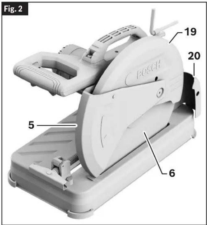
Fig. 2 19 20 5 6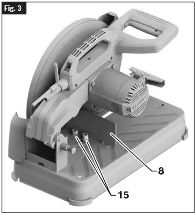
text_image
Fig. 3 8 1515 Vise Stop Bolts - Locks Vice Stop 8 into desired position. Can be loosened for fence adjustment and for angled mitering.
16 Tool Arm
17 Head Assembly
18 Head Assembly Lock Pin - Used to lock the tool head assembly in the lower position for transporting.
19 Upper Guard - Covers upper portion of the abrasive wheel.
20 Adjustable Spark Guard – Can be adjusted to deflect sparks away from workpiece.
21 Power Cord
Unpacking and Checking Contents
Unpacking the Abrasive Cut-Off Machine
When removing this tool from packaging materials, locate and reach down to the main carry handle and slowly lift until it clears the package.
Checking Contents in Package
(Fig. 4)
Open the top of the package and look for all the included parts. Refer to the diagram below.
Fig. 4

text_image
Parts ✓ Check off for each part □ 8 mm hex keyAssembly
WARNING
To avoid possible injury, always disconnect plug from power source before any assembly, adjustments or repairs.
Removing the Cut-Off Wheel
(Fig. 1, Fig. 5, Fig. 6)
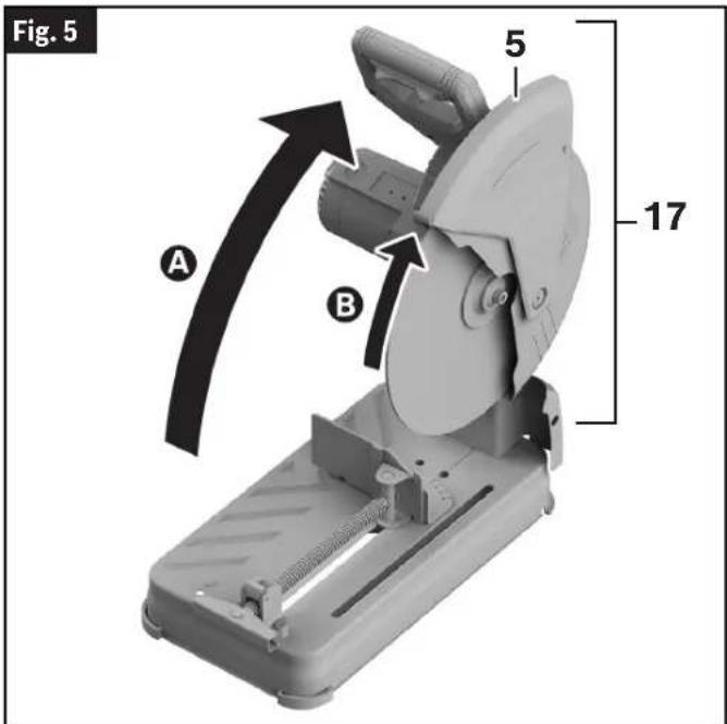
- Position the Saw Head Assembly 17 in the UP position A If in the DOWN position, press down slightly on the Saw Head Assembly 17 and pull out the Head Assembly Lock Pin 18. Then allow the Saw Head Assembly 17 to come up.
- Rotate Lower Wheel Guard 5 up B until there is clear access to the Outer Washer and Hex Bolt 25.
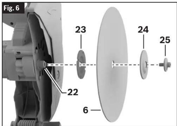
- Press and hold the Spindle Lock 7. Rotate the Cut-Off Wheel 6 slowly until it fully seats into its locked position. Rotate the Outer Washer and Hex Bolt 25 counterclockwise using the provided 8 mm Hex Key 13 to loosen the Cut-Off Wheel 6.
- Remove the Outer Washer and Hex Bolt 25 and the Outside Flange 24. Slide the Cut-Off Wheel 6 completely off the Spindle Shaft 22.
text_image
Fig. 5 A B 5 17Installing the 14" (355 mm) Cut-Off Wheel
(Fig. 1, Fig. 6)
WARNING To reduce risk of injury, use reinforced 14" (355 mm) Cut-Off Wheel rated 4100/min (RPM) or greater.
- Follow all steps in "Removing the Cut-Off Wheel."
- With the Lower Wheel Guard 5 up, carefully place the Inner Flange 23 and new Cut-Off Wheel 6 onto the Spindle Shaft 22.
- Fit the Outer Flange 24 and Outer Washer/Bolt Assembly 25. Once fitted, finger-tighten the Outer Washer/Bolt Assembly 25 clockwise into the Spindle Shaft 22.
- Press and hold the Spindle Lock 7.
- Using the 8 mm Hex Key 13, rotate the Outer Washer/Bolt Assembly 25 clockwise until it fully seats into its lock position.
- Using the 8 mm Hex Key 13, tighten the Outer Washer/Bolt Assembly 25 clockwise. (ATTENTION: DO NOT OVERTIGHTEN.)
- Release the Spindle Lock 7 and Rotate the Lower Wheel Guard 5 down.
- Ensure the Cut-Off Wheel 6 can rotate freely and does not make contact with the Lower Wheel Guard 5 or the Upper Guard 19.
- Place the 8 mm Hex Key 13 back in storage area on the power cord.
text_image
Fig. 6 23 24 25 22 6Adjustments
WARNING
To avoid possible injury, always disconnect plug from power source before any assembly, adjustments or repairs.
Using the Head Assembly Lock Pin
Head Assembly Lock Pin
(Fig. 7)
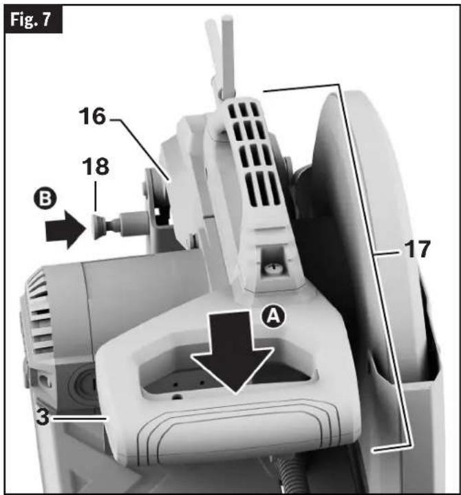
The Head Assembly Lock Pin 18 is located on the left side of the tool near the Tool Arm 16. It is used to hold the tool's head assembly in the DOWN position. This position prevents the head from bouncing up and down during transportation. This also makes the tool more compact for lifting and storage.
To Engage the Head Assembly Lock Pin
(Fig. 7)
- Grasp the tool's Main Handle 3 and press down on the head assembly Ⓐ
- While pressing the tool head down, push in on the Head Assembly Lock Pin 18 B Release the Head Assembly 17. The Head Assembly 17 will be locked in the DOWN position.
text_image
Fig. 7 16 18 B 17 A 3To Disengage the Head Assembly Lock Pin
(Fig. 8)
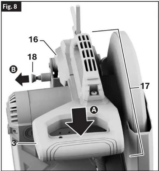
- Grasp the Main Handle 3 and press down on the head assembly A
- While pressing the head down, pull out the Head Assembly Lock Pin 18 ☑While maintaining your grip on the Main Handle 3, release the Lock Pin 18. Slowly allow the spring-loaded Head Assembly 17 to come up to the top of its travel and then release the Main Handle 3.
text_image
Fig. 8 16 18 B 17 A 3Adjustments
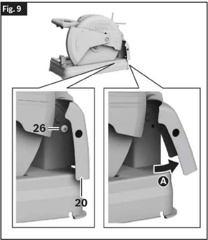
Using the Adjustable Spark Guard
(Fig. 9)
Adjustable Spark Guard
The Adjustable Spark Guard 20 is located on the rear right side of the tool.
It can be adjusted to deflect sparks away from the workpiece.
Adjusting the Spark Guard
-
Using a Phillips head screwdriver, turn the Spark Guard Adjustment Screw 26 counterclockwise to loosen the Spark Guard 20.
-
Adjust the Spark Guard 20 to the desired location A and retighten.
text_image
Fig. 9 26 20 ATransporting and Mounting
WARNING
To avoid possible injury, always disconnect plug from power source before any assembly, adjustments or repairs.
WARNING
Lift this tool ONLY by the carry handle.
WARNING damage.
Never lift tool by holding main handle. This may cause serious
WARNING
Never lift the tool by the pow- er cord. Attempting to lift or
carry the tool by the power cord will damage the insulation and the wire connections, resulting in electric shock or fire.
WARNING
Place the tool on a firm, level surface where there is plenty of room for handling and properly supporting the workpiece.
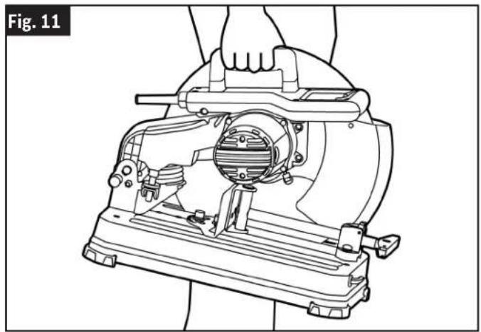
Lifting Saw with Carry Handle
(Fig. 10, Fig. 11)
-
Push the tool's Head Assembly 17 down and lock in DOWN position using the Head Assembly Lock Pin 18.
-
Push the Vise Clamp 9 all the way towards the Vise Stop 8. Engage the Quick Release Lock Lever 10, then tighten the Vise Clamp 9.
Transport the tool by firmly gripping the Main Carry Handle 4. When transporting the tool, ensure the wheel side is directed toward your body.
Transporting and Mounting
Fig. 10
text_image
17 4 18 10 8 9Mounting Applications
WARNING Be certain the abrasive cut-off machine is mounted or placed on a level, firm work surface before using. A level and firm work surface reduces the risk of the cut-off machine becoming unstable.
Workbench Permanent Attachment
(Fig. 12)
CAUTION
Be careful not to over-torque the bolt. This could damage
base.
- Each of the two mounting holes should be bolted securely using 5/16" (M8) bolts, lock washers and hex nuts (not included).
- Locate and mark where the saw is to be mounted.
- Drill two 5/16" (8 mm) diameter holes through workbench.
- Place the abrasive cut-off machine on the workbench, aligning the Mounting Holes 12 in the base with the holes drilled in the workbench. Install bolts, lock washers and hex nuts.
natural_image
Line drawing of a hand operating a mechanical device with no visible text or symbols
natural_image
3D rendering of a mechanical cutting machine with labeled parts (no text or symbols on the device itself)Preparing for Saw Operations
WARNING
To avoid possible injury, always disconnect plug from power source before any assembly, adjustments or repairs.
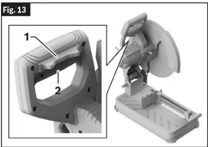
Switch Activation
(Fig. 13)
For safety, the Power Switch 2 is designed to prevent accidental starts.
To Turn the Tool On
Slide the Switch Lock-Off Release Button 1 with either thumb to disengage the lock. Then pull the Power Switch 2 and release the Switch Lock-Off Release Button 1.
To Turn the Tool Off
Release the Power Switch 2.
When the Power Switch 2 is released, the Switch Lock-Off Release Button 1 will lock the Power Switch 2 automatically, and the lever will no longer operate until either Lock-Off Release Button 1 is engaged again.
text_image
Fig. 13 1 2Long Workpiece Support
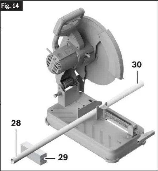
(Fig. 14)
Support long workpieces to prevent sagging. Use an Auxiliary Workpiece Support 29 for Long Workpieces 28, opposite the Cut-Off End 30.
text_image
Fig. 14 30 28 29Preparing for Saw Operations
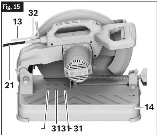
Using the Vise Stop
(Fig. 1, Fig. 15, Fig. 16)
The cut-off machine has an adjustable fence to accommodate varying sizes of workpiece.
Clamping and Releasing the Workpiece
(Fig. 17)
Properly position the workpiece. Make sure that
- With the 8 mm Hex Key 13, loosen the Vise the workpiece is clamped firmly against the Vise Stop Bolts 15 by rotating them counterclock-Clamp 9 and Vise Stop 8. wise. Do NOT REMOVE the bolts.
- The Vise Stop 8 can be moved forward or backward to the desired Mounting Location 31.
- The Vise Stop 8 can also be aligned to the desired angle on the Vise-Stop Scale 33 with the Index Line 34 on the base.
Note: The Vise Stop 8 can be angled between 0^ and 45^ .
- Use the 8 mm Hex Key 13 to firmly tighten the Vise Stop Bolts 15 by rotating them clockwise.
- Place the 8 mm Hex Key 13 back in the Hex Key Storage Area 32 on the Power Cord 21.
text_image
Fig. 15 13 32 21 -14 3131-31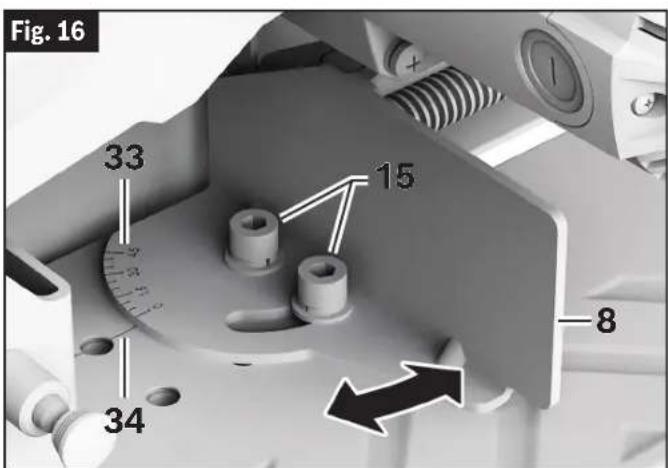
text_image
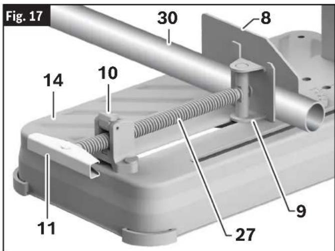
Fig. 16 33 15 8 34Clamping the Workpiece
(Fig. 17)
- Place the Workpiece 30 on the Base 14 of the saw and ensure it is firmly against the Vise Stop 8.
- Put the Quick Release Lock Lever 10 into the UP position and slide the Locking Spindle 27 toward the Workpiece 30 using the Vice Handle 11.
- When the Vice Clamp 9 is securely against the Workpiece 30, put the Quick Release Lock Lever 10 into the DOWN position.
- Rotate the Vice Handle 11 clockwise to securely tighten the Vice Clamp 9 to the Workpiece 30.
Releasing the Workpiece
(Fig. 17)
- Rotate the Vice Handle 11 counterclockwise to loosen the Vice Clamp 9 from the workpiece.
- Put the Quick Release Lock Lever 10 into the UP position.
- Using the Vice Handle 11, slide the Locking Spindle 27 away from the workpiece.
text_image
Fig. 17 30 8 10 14 11 27 9Saw Operations
WARNING
To avoid possible injury, always disconnect plug from power source before any assembly, adjustments or repairs.
Making a Cut
(Fig. 1, Fig. 18)
WARNING
The cut off machine should always be on a level and stable
work surface. Operating the cut off machine on an unstable work surface can result in personal injury and property damage.
WARNING
The operator must wear hearing protection when operating
the cut-off saw, and gloves when handling wheels.
Be aware of the path of the wheel. Make a dry run with the saw OFF by conducting a simulated cutting cycle and observe the projected path of the wheel. Keep hands at least 6 inches away from the projected path of the saw wheel.
- Properly position the Workpiece 28. Make sure that the workpiece is clamped firmly with the Vise Clamp 9 and against the Vise Stop 8.
- Activate the Power Switch 2 to turn On the tool. (See "Switch Activation" on page 16.) Wait until the tool reaches its maximum speed. Lower the Head Assembly 17 and make your cut A
- Turn OFF the tool and wait until the Wheel 6 comes to a complete stop before returning the Head Assembly 17 to the raised position and/or removing the Workpiece 28.
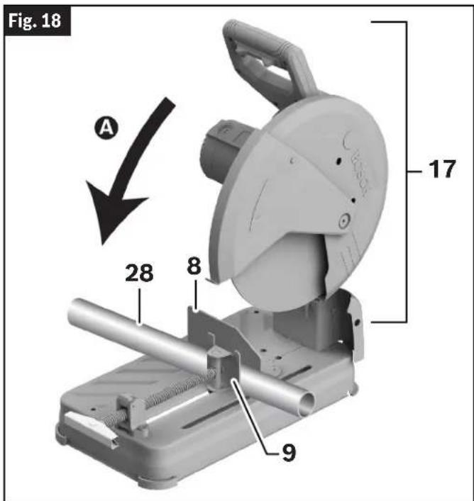
text_image
Fig. 18 A 28 8 9 17Maintenance and Lubrication
⚠ WARNING To avoid possible injury, always disconnect plug from power source before any assembly, adjustments or repairs.
Service
WARNING All repairs, electrical or mechanical, should be attempted
only by trained repairmen. Contact the nearest Factory Service Center or Authorized Service Station or other competent repair service. Use only identical replacement parts, any other may create a hazard.
Power Cord
If the power cord is worn or cut, or damaged in any way, have it replaced immediately.
Care of Abrasive Wheels
WARNING Handle and store all abrasive wheels carefully to prevent damage from thermal shock, heat, mechanical damage, etc. Store in a dry protected area free from high humidity, freezing temperatures or extreme temperature changes. Before use check accessory for cracks and fractures, do not use if damage is suspected.
Tool Lubrication
Preventive maintenance performed by unauthorized personnel may result in misplacing of internal wires and components which could cause serious hazard. We recommend that all tool service be performed by a Bosch Factory Service Center or Authorized Bosch Service Station.
Your Bosch tool has been properly lubricated and is ready to use. It is recommended that tools with gears be regreased with a special gear lubricant at every brush change.
Motor Brushes
The brushes and commutator in your tool have been engineered for many hours of dependable service. To maintain peak efficiency of the motor, we recommend every 2-6 months the brushes be examined. Only genuine Bosch replacement brushes specially designed for your tool should be used.
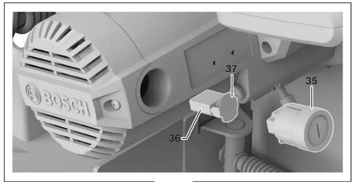
Motor Brush Replacement
(Fig. 19)
To inspect or replace brushes:
- Unplug the saw.
- Remove the Brush Cap 35 on the motor using a wide, flat-blade screwdriver.
Note: The Brush Cap 35 is spring-loaded by the brush assembly. - Pull out the Brush 36. Repeat for the opposite side.
Note: If installing the existing Brush or Brushes 36, make sure the Brush 36 goes in the same way it came out. Otherwise, a break-in period will occur that will reduce motor performance and increase brush wear. - Inspect Brushes 36 for wear. On the wide, flat side of Brush 36 is a wear limit line. If the brush contact face is at or beyond (no line visible) the limit, replace Brushes 36 as a set.
- Install new Brush 36. The two tabs on the Brush Terminal 37 go in the same hole the carbon part fits into.
- Tighten the Brush Cap 35 but do not overtighten.
Bearings
All bearings in this tool are lubricated with a sufficient amount of high-grade lubricant for the life of the unit under normal operating conditions. No further lubrication is required. After about 300-400 hours of operation, or at every second brush change, the bearings should be replaced at a Bosch Factory Service Center or Authorized Bosch Service Center. Bearings that become noisy (due to heavy load or very abrasive material cutting) should be replaced at once to avoid overheating or motor failure.
Maintenance and Lubrication
Fig. 19
text_image
BOSCH 36 37 35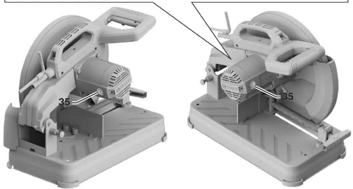
natural_image
Two industrial cutting machines with visible internal components and mounting base (no text or symbols)Cleaning
CAUTION
Certain cleaning agents and solvents damage plastic parts.
Some of these are: gasoline, carbon tetrachloride, chlorinated cleaning solvents, ammonia, and household detergents that contain ammonia. Avoiding use of these types of cleaning agents will minimize the possibility of damage.
CAUTION
Do not clean inside of motor openings with pointed ob-
jects. Damage to electronics or wiring can occur.
Troubleshooting
| Problem Cause Corrective Action | ||
| Tool will not start. 1. Power cord | is not plugged in.2. Fuse or circuit breaker tripped.3. Power cord is damaged.4. Burned out switch. | 1. Connect the power cord to an electrical outlet.2. Replace fuse or reset tripped circuit breaker.3. Have cord replaced by an Authorized Bosch Service Center or Service Station.4. Have switch replaced by an Authorized Bosch Service Center or Service Station. |
| Wheel does not come up to speed. | Extension cord is too light or too long.Low house voltage. | Replace with adequate cord.Contact your electric company. |
| Excessive vibration. 1. Abrasive wheel is out of balance.Saw is not mounted securely to stand or workbench.Abrasive wheel bolt is not tight. | wheel is out of balance.Saw is not mounted securely to stand or workbench.Abrasive wheel bolt is not tight. | Replace wheel.Tighten all mounting hardware.See “Removing the Cut-Off Wheel” on page 12 and ‘Installing the 14” (355 mm) Cut-Off Wheel’ on page 12. |
Attachments and Accessories
| Item | Catalog Number |
| 14 in. Abrasive Cut-Off Wheel | CW1S1400 |
Maintenance et lubrification....39
Service....39
Cordon d'alimentation....39
Entretien des meules abrasives 39
natural_image
Line drawing of a mechanical device with a hand operating it, no text or symbols presentnatural_image
3D rendering of a mechanical cutting machine with labeled parts (no text or symbols on the device itself)natural_image
Two industrial cutting machines with labeled components, shown from different angles (no text or symbols on the machines themselves)Nettoyage
MISE EN GARDE
natural_image
Line drawing of a hand operating a mechanical device with no visible text or symbols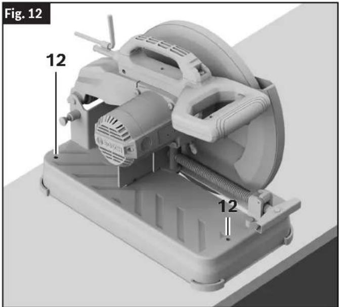
natural_image
3D rendering of a mechanical cutting machine with labeled parts (no text or symbols beyond labels)natural_image
Two industrial cutting machines with labeled parts, shown from different angles (no text or symbols on the machines themselves)Limpieza
PRECAUCION
This page was intentionally left blank.
This page was intentionally left blank.
For details on the terms of the limited warranty for this product, go to https://rb-pt.io/PowerToolWarranty or call 1-877-BOSCH99.
GARANTIE LIMITÉE
© Robert Bosch Tool Corporation
1800 W. Central Road
Mt. Prospect, IL 60056-2230
160992A9A1 05/2024