GCM18V-07S Professional - Saw BOSCH - Free user manual and instructions
Find the device manual for free GCM18V-07S Professional BOSCH in PDF.

User questions about GCM18V-07S Professional BOSCH
0 question about this device. Answer the ones you know or ask your own.
Ask a new question about this device
Download the instructions for your Saw in PDF format for free! Find your manual GCM18V-07S Professional - BOSCH and take your electronic device back in hand. On this page are published all the documents necessary for the use of your device. GCM18V-07S Professional by BOSCH.
USER MANUAL GCM18V-07S Professional BOSCH
IMPORTANT Read Before Using
IMPORTANT Lire avant usage
IMPORTANTE Leer antes de usar

natural_image
Icon of a person reading a book inside a circle (no text or symbols)Operating / Safety Instructions Consignes d'utilisation / de sécurité Instrucciones de funcionamiento y seguridad
GCM18V-07S
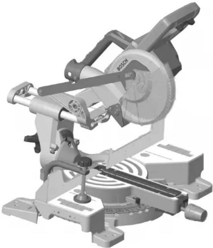
natural_image
3D rendering of a Bosch cutting machine with visible blade and mounting base (no text or symbols)
BOSCH
Call Toll Free for Consumer Information & Service Locations Pour obtenir des informations et les adresses de nos centres de service après-vente, appelez ce numéro gratuit Llame gratis para obtener información para el consumidor y ubicaciones de servicio
1-877-BOSCH99 (1-877-267-2499) www.boschtools.com
For English Version See page 2
| The definitions below describe the level of severity for each signal word.Please read the manual and pay attention to these symbols. | |
 | This is the safety alert symbol. It is used to alert you to potential personal injury hazards. Obey all safety messages that follow this symbol to avoid possible injury or death. |
 | DANGER indicates a hazardous situation which, if not avoided, will result in death or serious injury. |
 | WARNING indicates a hazardous situation which, if not avoided, could result in death or serious injury. |
 | CAUTION indicates a hazardous situation which, if not avoided, could result in minor or moderate injury. |
Table of Contents
Safety Symbols 2
General Power Tool Safety Warnings....3
Safety Instructions for Miter Saws ....5
Additional Safety Rules....7
Symbols....8
Getting to Know Your Miter Saw.... 10
Specifications 14
Intended Use.... 14
Cutting Masonry/Metal 14
Cutting Capacities.... 15
Unpacking and Checking Contents 16
Unpacking the Miter Saw 16
Checking Contents in Package 16
Tools Needed For Assembly 17
Verifying Parts 17
Checking Combination Square.... 17
Assembly.... 18
Storing the Torx Wrench 18
Inserting and Releasing Battery Pack 18
Removing and Installing Blades 19
Assembling Dust Collection System 20
Adjustments 22
Using the Head Assembly Lock Pin....22
Miter Detent System - Adjustment Procedure .. 23
0° Bevel Stop 24
45° Bevel Stop 25
Transporting and Mounting 27
Lifting the Saw.... 27
Mounting Applications 28
Preparing for Saw Operations 29
Switch Activation.... 29
Built-in LED Light.... 29
Body and Hand Position 29
Workpiece Support 32
Saw Operations.... 34
Brake Operation 34
Using the Miter Lock Knob 34
Using Miter Detent System 34
Chop Cuts 35
Slide Cuts.... 36
Miter Cuts.... 37
Bevel Cuts 38
Compound Cuts. 40
Cutting Base Molding 41
Cutting Crown Molding 42
Table of Contents
Special Cuts. 46
Maintenance and Lubrication.... 47
Service 47
Batteries.... 47
Care of Blades 47
Tool Lubrication.... 47
Bearings.... 47
Cleaning 47
Troubleshooting 48
Troubleshooting Guide - Electrical 48
Troubleshooting Guide - General 49
Attachments and Accessories 50
General Power Tool Safety Warnings
WARNING
Read all safety warnings, instructions, illustrations and specifications provided with this power tool. Failure to follow all instructions listed below may result in electric shock, fire and/or serious injury.
SAVE ALL WARNINGS AND INSTRUCTIONS FOR FUTURE REFERENCE
The term “power tool” in the warnings refers to your mains-operated (corded) power tool or battery-operated (cordless) power tool.
1. Work area safety
a. Keep work area clean and well lit. Cluttered or dark areas invite accidents.
b. Do not operate power tools in explosive atmospheres, such as in the presence of flammable liquids, gases or dust. Power tools create sparks which may ignite the dust or fumes.
c. Keep children and bystanders away while operating a power tool. Distractions can cause you to lose control.
2. Electrical safety
a. Power tool plugs must match the outlet. Never modify the plug in any way. Do not use any adapter plugs with earthed (grounded) power tools. Unmodified plugs and matching outlets will reduce risk of electric shock.
b. Avoid body contact with earthed or grounded surfaces, such as pipes, radiators, ranges and refrigerators. There is an increased risk of electric shock if your body is earthed or grounded.
c. Do not expose power tools to rain or wet conditions. Water entering a power tool will increase the risk of electric shock.
d. Do not abuse the cord. Never use the cord for carrying, pulling or unplugging the power tool. Keep cord away from heat, oil, sharp edges or moving parts. Damaged or entangled cords increase the risk of electric shock.
e. When operating a power tool outdoors, use an extension cord suitable for outdoor use. Use of a cord suitable for outdoor use reduces the risk of electric shock.
f. If operating a power tool in a damp location is unavoidable, use a Ground Fault Circuit Interrupter (GFCI) protected supply. Use of an GFCI reduces the risk of electric shock.
General Power Tool Safety Warnings
3. Personal safety
a. Stay alert, watch what you are doing and use common sense when operating a power tool. Do not use a power tool while you are tired or under the influence of drugs, alcohol or medication. A moment of inattention while operating power tools may result in serious personal injury.
b. Use personal protective equipment. Always wear eye protection. Protective equipment such as a dust mask, non-skid safety shoes, hard hat, or hearing protection used for appropriate conditions will reduce personal injuries.
c. Prevent unintentional starting. Ensure the switch is in the off-position before connecting to power source and / or battery pack, picking up or carrying the tool. Carrying power tools with your finger on the switch or energizing power tools that have the switch on invites accidents.
d. Remove any adjusting key or wrench before turning the power tool on. A wrench or a key left attached to a rotating part of the power tool may result in personal injury.
e. Do not overreach. Keep proper footing and balance at all times. This enables better control of the power tool in unexpected situations.
f. Dress properly. Do not wear loose clothing or jewelry. Keep your hair and clothing away from moving parts. Loose clothes, jewelry or long hair can be caught in moving parts.
g. If devices are provided for the connection of dust extraction and collection facilities, ensure these are connected and properly used. Use of dust collection can reduce dust-related hazards.
h. Do not let familiarity gained from frequent use of tools allow you to become complacent and ignore tool safety principles. A careless action can cause severe injury within a fraction of a second.
4. Power tool use and care
a. Do not force the power tool. Use the correct power tool for your application. The correct power tool will do the job better and safer at the rate for which it was designed.
b. Do not use the power tool if the switch does not turn it on and off. Any power tool that cannot be controlled with the switch is dangerous and must be repaired.
c. Disconnect the plug from the power source and/or remove the battery pack, if detachable, from the power tool before making any adjustments, changing accessories, or storing power tools. Such preventive safety measures reduce the risk of starting the power tool accidentally.
d. Store idle power tools out of the reach of children and do not allow persons unfamiliar with the power tool or these instructions to operate the power tool. Power tools are dangerous in the hands of untrained users.
e. Maintain power tools and accessories. Check for misalignment or binding of moving parts, breakage of parts and any other condition that may affect the power tool's operation. If damaged, have the power tool repaired before use. Many accidents are caused by poorly maintained power tools.
f. Keep cutting tools sharp and clean. Properly maintained cutting tools with sharp cutting edges are less likely to bind and are easier to control.
g. Use the power tool, accessories and tool bits etc. in accordance with these instructions, taking into account the working conditions and the work to be performed. Use of the power tool for operations different from those intended could result in a hazardous situation.
h. Keep handles and grasping surfaces dry, clean and free from oil and grease. Slippery handles and grasping surfaces do not allow for safe handling and control of the tool in unexpected situations.
General Power Tool Safety Warnings
5. Battery tool use and care
a. Recharge only with the charger specified by the manufacturer. A charger that is suitable for one type of battery pack may create a risk of fire when used with another battery pack.
b. Use power tools only with specifically designated battery packs. Use of any other battery packs may create a risk of injury and fire.
c. When battery pack is not in use, keep it away from other metal objects like paper clips, coins, keys, nails, screws, or other small metal objects that can make a connection from one terminal to another. Shorting the battery terminals together may cause burns or a fire.
d. Under abusive conditions, liquid may be ejected from the battery, avoid contact. If contact accidentally occurs, flush with water. If liquid contacts eyes, additionally seek medical help. Liquid ejected from the battery may cause irritation or burns.
e. Do not use a battery pack or tool that is damaged or modified. Damaged or modified batteries may exhibit unpredictable behavior resulting in fire, explosion or risk of injury.
f. Do not expose a battery pack or tool to fire or excessive temperature. Exposure to fire or temperature above 265 °F may cause explosion.
g. Follow all charging instructions and do not charge the battery pack or tool outside the temperature range specified in the instructions. Charging improperly or at temperatures outside the specified range may damage the battery and increase the risk of fire.
6. Service
a. Have your power tool serviced by a qualified repair person using only identical replacement parts. This will ensure that the safety of the power tool is maintained.
b. Never service damaged battery packs. Service of battery packs should only be performed by the manufacturer or authorized service providers.
Safety Instructions for Miter Saws
a. Miter saws are intended to cut wood or wood-like products, they cannot be used with abrasive cut-off wheels for cutting ferrous material such as bars, rods, studs, etc. Abrasive dust causes moving parts such as the lower guard to jam. Sparks from abrasive cutting will burn the lower guard, the kerf insert and other plastic parts.
b. Use clamps to support the workpiece whenever possible. If supporting the workpiece by hand, you must always keep your hand at least 100 mm (4") from either side of the saw blade. Do not use this saw to cut pieces that are too small to be securely clamped or held by hand. If your hand is placed too close to the saw blade, there is an increased risk of injury from blade contact.
c. The workpiece must be stationary and clamped or held against both the fence and the table. Do not feed the workpiece into the blade or cut "freehand" in any way. Unrestrained or moving workpieces could be thrown at high speeds, causing injury.
d. Push the saw through the workpiece. Do not pull the saw through the workpiece. To make a cut, raise the saw head and pull it out over the workpiece without cutting, start the motor, press the saw head down and push the saw through the workpiece. Cutting on the pull stroke is likely to cause the saw blade to climb on top of the workpiece and violently throw the blade assembly towards the operator.
e. Never cross your hand over the intended line of cutting either in front or behind the saw blade. Supporting the workpiece "cross handed" i.e. holding the workpiece to the right of the saw blade with your left hand or vice versa is very dangerous.
f. Do not reach behind the fence with either hand closer than 100 mm (4") from either side of the saw blade, to remove wood scraps, or for any other reason while the blade is spinning. The proximity of the spinning saw blade to your hand may not be obvious and you may be seriously injured.
Safety Instructions for Miter Saws
g. Inspect your workpiece before cutting. If the workpiece is bowed or warped, clamp it with the outside bowed face toward the fence. Always make certain that there is no gap between the workpiece, fence and table along the line of the cut. Bent or warped workpieces can twist or shift and may cause binding on the spinning saw blade while cutting. There should be no nails or foreign objects in the workpiece.
h. Do not use the saw until the table is clear of all tools, wood scraps, etc., except for the workpiece. Small debris or loose pieces of wood or other objects that contact the revolving blade can be thrown with high speed.
i. Cut only one workpiece at a time. Stacked multiple workpieces cannot be adequately clamped or braced and may bind on the blade or shift during cutting.
j. Ensure the miter saw is mounted or placed on a level, firm work surface before use. A level and firm work surface reduces the risk of the miter saw becoming unstable.
k. Plan your work. Every time you change the bevel or miter angle setting, make sure the adjustable fence is set correctly to support the workpiece and will not interfere with the blade or the guarding system. Without turning the tool "ON" and with no workpiece on the table, move the saw blade through a complete simulated cut to assure there will be no interference or danger of cutting the fence.
I. Provide adequate support such as table extensions, saw horses, etc. for a workpiece that is wider or longer than the table top. Workpieces longer or wider than the miter saw table can tip if not securely supported. If the cut-off piece or workpiece tips, it can lift the lower guard or be thrown by the spinning blade.
m. Do not use another person as a substitute for a table extension or as additional support. Unstable support for the workpiece can cause the blade to bind or the workpiece to shift during the cutting operation pulling you and the helper into the spinning blade.
n. The cut-off piece must not be jammed or pressed by any means against the spinning saw blade. If confined, i.e. using length stops, the cut-off piece could get wedged against the blade and thrown violently.
o. Always use a clamp or a fixture designed to properly support round material such as rods or tubing. Rods have a tendency to roll while being cut, causing the blade to "bite" and pull the work with your hand into the blade.
p. Let the blade reach full speed before contacting the workpiece. This will reduce the risk of the workpiece being thrown.
q. If the workpiece or blade becomes jammed, turn the miter saw off. Wait for all moving parts to stop and disconnect the plug from the power source and/or remove the battery pack. Then work to free the jammed material. Continued sawing with a jammed workpiece could cause loss of control or damage to the miter saw.
r. After finishing the cut, release the switch, hold the saw head down and wait for the blade to stop before removing the cut-off piece. Reaching with your hand near the coasting blade is dangerous.
s. Hold the handle firmly when making an incomplete cut or when releasing the switch before the saw head is completely in the down position. The braking action of the saw may cause the saw head to be suddenly pulled downward, causing a risk of injury.
t. Avoid overheating the saw blade tips.
Additional Safety Rules
GFCI and personal protection devices like electrician's rubber gloves and footwear will further enhance your personal safety.
Do not use AC only rated tools with a DC power supply. While the tool may appear to work, the electrical components of the AC rated tool are likely to fail and create a hazard to the operator.
Keep handles dry, clean and free from oil and grease. Slippery hands cannot safely control the power tool.
Develop a periodic maintenance schedule for your tool. When cleaning a tool be careful not to disassemble any portion of the tool since internal wires may be misplaced or pinched or safety guard return springs may be improperly mounted. Certain cleaning agents such as gasoline, carbon tetrachloride, ammonia, etc. may damage plastic parts.
WARNING
Some dust created by power sanding, sawing, grinding, drilling, and
other construction activities contains chemicals known to cause cancer, birth defects or other reproductive harm. Some examples of these chemicals are:
- Lead from lead-based paints,
- Crystalline silica from bricks and cement and other masonry products, and
- Arsenic and chromium from chemically-treated lumber.
Your risk from these exposures varies, depending on how often you do this type of work. To reduce your exposure to these chemicals: work in a well ventilated area, and work with approved safety equipment, such as those dust masks that are specially designed to filter out microscopic particles.
WARNING
Do not use the Bosch GCM18V-07S miter saw to cut fiber cement
board. Cutting materials containing crystalline silica may create exposures to respirable silica dust.
WARNING
Before each use, review all warnings located on the miter saw.

text_image
WARNING Wear Eye ProtectionThe operation of any power tool can result in foreign objects being thrown into the eyes, which can result in severe eye damage. Always wear safety goggles that comply with ANSI Z87.1 (shown on pack age) before commencing power tool operation.
WARNING
Do not use this miter saw without properly installed base extensions.
Lack of appropriate workpiece support may result in personal injury.

natural_image
Prohibition sign showing a hand crossed out by a diagonal line, indicating no prohibition or exclusion (no text present)
Avoid positioning hands, fingers or arms. A danger zone – never lift or carry saw by the main switch handle.
Symbols
Important: Some of the following symbols may be used on your tool. Please study them and learn their meaning. Proper interpretation of these symbols will allow you to operate the tool better and safer.
| Symbol Designation/Explanation | |
| V Volts (voltage) | |
| A Amperes (current) | |
| Hz Hertz (frequency, cycles per second) | |
| W Watt (power) | |
| kg Kilograms (weight) | |
| min Minutes (time) | |
| s Seconds (time) | |
| CFM Cubic feet per minute [or ft ^3 /min] (air flow rate) | |
| ∅ | Diameter (size of drill bits, grinding wheels, etc.) |
| n_0 | No load speed (rotational speed, at no load) |
| n Rated speed (Maximum attainable speed) | |
| .../min Revolutions or reciprocation per minute (revolutions, strokes, surface speed, orbits etc. per minute) | |
| O Off position (zero speed, zero torque...) | |
| 1, 2, 3, ...I, II, III, | Selector settings (speed, torque or position settings. Higher number means greater speed) |
| 0 | Infinitely variable selector with off (speed is increasing from 0 setting) |
| → | Arrow (action in the direction of arrow) |
| ~ | Type or a characteristic of current |
| === | Type or a characteristic of current |
| ~ | Type or a characteristic of current |
| ☐ | Designates Double Insulated Construction tools |
| ⊕ | Grounding terminal |
Symbols
Important: Some of the following symbols may be used on your tool. Please study them and learn their meaning. Proper interpretation of these symbols will allow you to operate the tool better and safer.
| Symbol Designation/Explanation | |
 | Designates Li-ion battery recycling program. |
 | Alerts user to read manual. |
 | Alerts user to wear eye protection. |
 | This symbol designates that this tool is listed by Underwriters Laboratories. |
 | This symbol designates that this tool is listed by Underwriters Laboratories, to United States and Canadian Standards. |
 | This symbol designates that this tool is listed by the Canadian Standards Association. |
 | This symbol designates that this tool is listed by the Canadian Standards Association, to United States and Canadian Standards. |
 | This symbol designates that this tool is listed by the Intertek Testing Services, to United States and Canadian Standards. |
Getting to Know Your Miter Saw
GCM18V-07S Cordless Miter Saw
Fig. 1
text_image
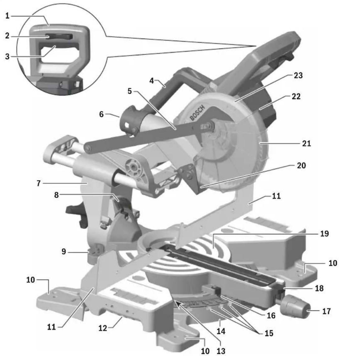
Technical diagram of a Bosch industrial cutting machine with numbered components and an inset view of the component.Getting to Know Your Miter Saw
1 Main Handle is used to raise and lower the head assembly and contains the power switch. Pull the handle down to lower the blade to the workpiece.
2 Switch Lock-OFF Release Buttons two buttons, one of which must be pressed before the power switch can be pressed.
3 Power Switch is used with the "Lock-OFF" button to turn the saw off and on.
4 Main Carry Handle is used to carry the saw.
5 Lower Guard Link allows for smooth movement of the lower guard.
6 Dust Chute directs sawdust up into the dust bag or vacuum hose.
7 Bevel Post provides rotating support for all of the miter saw parts above the table.
8 Bevel Scale and Pointers indicates the current bevel angle. The large angled scale makes it easy to read bevel angles.
9 Bevel Stop Indicators allow you to select the most common bevel angles: 33.9°, 45°, or 47°.
10 Tool Mounting Pads in the four corners of the saw provide areas to clamp, bolt, or nail the saw to a flat work surface.
11 Stationary Fence is bolted to the base and supports the workpiece.
12 Cast-in Carry Handles are used to lift and transport the saw.
13 Miter Detent Plate Screws, four, accessible through holes in the miter scale, are loosened to allow the position of the detent plate to be adjusted.
14 Miter Detent Plate can be adjusted to set the accuracy of its detent locations.
15 Miter Detents, are ten slots that allow for fast and accurate miter cuts at common miter angles.
16 Miter Scale and Pointer allows you to see the angle setting before a cut is made. The pointer rotates with the table and blade and points to the angle on the miter scale.
17 Miter Lock Knob locks the miter saw table at any desired miter angle.
18 Miter Detent Button disengages the miter detents.
19 Table provides workpiece support, rotates for desired miter cuts, and rotates the head assembly. The front extended part of the table is called the miter arm.
20 Rubber Deflector is attached to the bottom of the dust chute and deflects dust into the chute.
21 Blade is the component that makes cuts in workpieces. Use only 7-1/4 (184 mm) diameter blades with 5/8" (15.88 mm) diameter arbor holes.
22 Lower Blade Guard/Lower Guard Lip helps protect your hands from the spinning blade. It retracts as the blade is lowered. Should the guard become jammed on a workpiece, the lip can be used to raise the lower guard.
23 Upper Guard covers upper part of the blade.
Getting to Know Your Miter Saw
Fig. 2
text_image
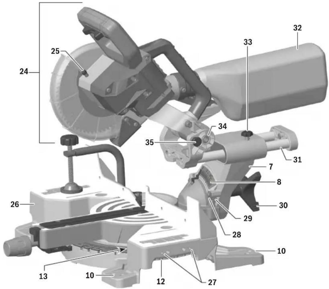
Technical diagram of a mechanical assembly with numbered parts for identification24 Head Assembly is the part of the saw that includes the blade, guards, motor, main handle, and dust collection system.
25 Arbor Lock, when pressed, keeps the blade from rotating. It's used during blade removal or installation, when loosening or tightening the arbor bolt.
26 Base provides the working surface that supports the workpiece.sw
27 Mounting Holes for Optional Crown Stop.
28 -2° Bevel Undercut Feature Screw secures the -2° undercut feature plate.
29 -2° Bevel Undercut Feature allows for -2° right bevel undercuts.
30 Bevel Lock Knob locks the head assembly at the desired bevel angle.
31 Slide System allows the head assembly to smoothly slide in and out. It can be locked all the way to the rear or in the fully-extended position.
32 Dust Bag collects the dust from sawing operations. To empty it, uncouple it from the dust port and open the zipper at the bottom.
33 Slide Rail Lock Knob when tightened, locks the slide system in place. Tighten by turning the knob clockwise (to the right), and loosen my turning counterclockwise (to the left).
34 Pivot Post provides support for and is the pivot point for the head assembly.
35 Head Assembly Lock Pin is used to lock the head assembly in the lower position.
Getting to Know Your Miter Saw
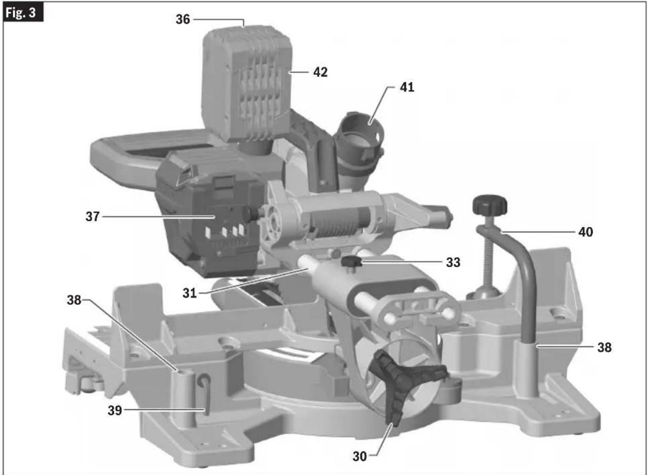
text_image
Fig. 3 36 42 41 37 33 40 38 31 38 39 3036 Battery Pack Release Button releases the battery pack so that it can be removed from the battery bay.
37 Battery Bay is where a Bosch or AMPShare battery pack (sold separately) is inserted.
38 Clamp Post Locations are two vertical post holes in the base provided to support the clamp.
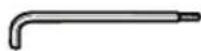
39 Torx Wrench is used to change the blade and to tighten and loosen the -2° Bevel Undercut Feature Screw (28).
40 Clamp is used to hold the workpiece to the table and base. The clamp is inserted into one of the clamp post locations.
41 Dust Port is the part that provides the connection to the dust bag or vacuum hose.
42 Battery Pack (sold separately)
Specifications
GCM18V-07S Cordless Miter Saw
| Voltage: 18 V --- | |
| Allowed ambient temperature:- during charging- during operation- during storage | 32...113°F (0...+45°C)-4...122°F (-20...+50°C)32...122°F (0...+50°C) |
Battery Packs/Chargers
Please refer to the battery/charger list, included with your tool.
Intended Use
WARNING
Use this miter saw only as intended. Unintended use may result in per-
sonal injury and property damage.
WARNING
This product is intended to cut wood, wood-like products, and non-ferrous
metals. Dust build-up around the lower guard and hub from other materials (masonry or ferrous metal) may disable the lower guard operation.
Cutting Masonry/Metal
WARNING
Do not cut ferrous metal or masonry with this miter saw. The dust
from the ferrous metal or masonry cutting will cause the lower guard to become sluggish and may not close fully and quickly after cutting these materials.
WARNING
Do not use abrasive wheels. This tool is not intended for usage with
metal or masonry cut-off wheels.
WARNING
Do not use Wet Diamond cutting off wheel or water feed devices
with this miter saw. Masonry cutting waste will enter the lower guard system, harden and cause the guard to become inoperable. Use of water in masonry cutting applications with an electric miter saw will cause electric shock hazards.
This tool is not intended for usage with metal or masonry cut-off wheels.
Cutting Capacities
| Key Moldings / Positioning Maximum Size | |
| Base Molding Against Fence * 3-1/2" (89 mm) | |
| 38° Crown Molding Angled Against Fence * 3-5/8" (92 mm) | |
| 45° Crown Molding Angled Against Fence * 3-3/4" (95 mm) | |
| Crown Molding Flat on Table 8-1/4" (210 mm) | |
| * Within miter range of 0° to 47° Left | |
| Miter / Bevel Maximum Height | |
| 0°/ 0° 2-1/8" (54 mm) | |
| 45°/ 0° 2-1/8" (54 mm) | |
| 0°/ 45° (Left) 1-1/2" (38 mm) | |
| Miter / Bevel Maximum Width | |
| 0°/ 0° 8-1/4" (210 mm) | |
| 45°/ 0° 5-3/4" (146 mm) | |
| 0°/ 45° (Left) 8-1/4" (210 mm) | |
Unpacking and Checking Contents
Unpacking the Miter Saw

To avoid severe pinching, never lift or move this saw by gripping any component of the mechanism support system.
When removing this tool from packaging materials, reach down to the two side carry-handle locations and slowly lift until it clears the package.
Checking Contents in Package
Open the top of the package and look for the included loose parts (Fig. 4).
Some small parts must be attached to the tool before it is ready for use.
Fig. 4
Loose Parts

Torx Wrench (39)

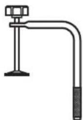
2 Workpiece Clamps (40)
natural_image
Simple line drawing of a laboratory apparatus with a stand and bent tube (no text or symbols)
Check off each part.

Operating/Safety Instructions

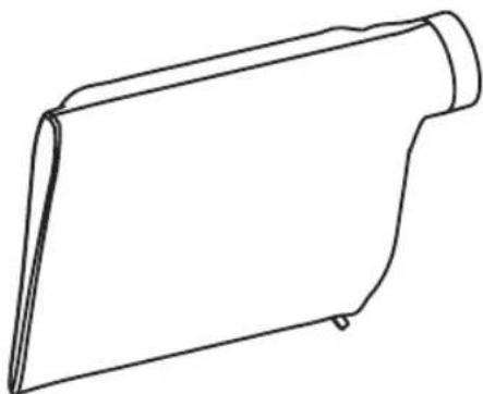
Dust Bag (32)
natural_image
Simple line drawing of a folded paper or scroll (no text or symbols)Tools Needed For Assembly
Verifying Parts
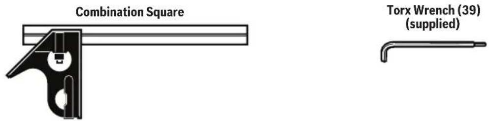
Check that you have the tools needed for the assembly of the saw, as shown in Fig. 5.
Checking Combination Square
Check that the combination square is true.
- Position the square and draw a light line as shown in Fig. 6.
- Flip the square as shown in Fig. 6.
- Check the edge of the flipped square against the drawn line, and make sure there is no gap or overlap at the bottom end as shown in Fig. 6.
Fig. 5
text_image
Combination Square Torx Wrench (39) (supplied)Fig. 6
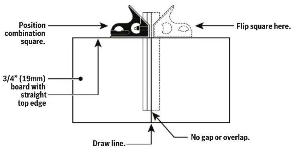
text_image
Position combination square. 3/4" (19mm) board with straight top edge Flip square here. Draw line. No gap or overlap.Assembly
WARNING
To avoid possible injury, disconnect battery pack before performing any assembly, adjustments or repairs.
Storing the Torx Wrench
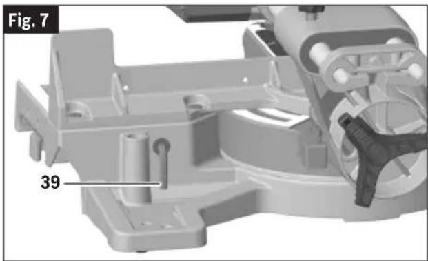
There is a storage location on the saw to store the Torx wrench (Fig. 7, 39). Insert the short leg of the Torx wrench through the rubber grommet as shown. Place the long leg into the tool rest.
NOTE: The Torx wrench (39) is needed to change the blade. If lost, use a Torx 30 wrench or a key.
natural_image
3D mechanical assembly diagram showing a component with labeled parts (no readable text or symbols)Inserting and Releasing Battery Pack
Slide charged battery pack (Fig. 8, 42) into the battery bay (37) until the battery pack locks into position.
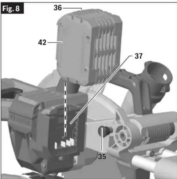
text_image
Fig. 8 36 42 37 35Your tool is equipped with a secondary locking latch to prevent the battery pack from completely falling out of the battery bay, should it become loose due to vibration.
To remove the battery pack, press the battery pack release button (36) and slide the battery pack completely out of the battery bay.
Assembly
Removing and Installing Blades
Always wear gloves when changing or handling blades. Blade tips can cause personal injury.
Removing Blade
- Position the saw in the UP position and at 0^ bevel. If in the DOWN position: while pressing down slightly on the saw head assembly, and pull out the head assembly lock pin (Fig. 8, 35). Then slowly allow the saw head assembly to come up.
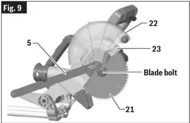
- Rotate the Lower Blade Guard (Fig. 9, 22) until there is clear access to the Blade Bolt.
text_image
Fig. 9 22 23 5 Blade bolt 21- Press and hold the arbor lock (the red button on the opposite side of the upper guard (23). Rotate the blade (21) slowly while pressing the arbor lock until it fully seats into its lock position.
- Using the Torx wrench (Fig. 7, 39), loosen the blade bolt by firmly turning it clockwise.
NOTE: This bolt has left-hand threads.
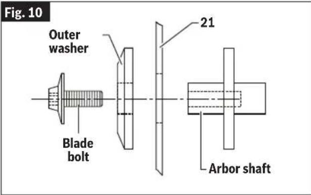
- Remove the blade bolt and outer washer. Carefully grab the blade. Slide the blade (Fig. 10, 21) away from the inner washer and off the arbor shaft, then down and away from the saw. Leave the inner washer on the arbor shaft.
text_image
Fig. 10 Outer washer Blade bolt 21 Arbor shaftInstalling 7-1/4" (184mm) Blade
WARNING To avoid injury, do not use a blade larger or smaller than 7-1/4"
(184mm) diameter and 5/8" (15.88 mm) arbor. The blade's maximum plate thickness is 5/64" (2 mm). The blade's maximum kerf thickness is 1/8" (3.175mm).
WARNING To reduce risk of injury, use saw blade rated 5000/min (RPM) or
greater.
WARNING After installing a new blade, make sure the blade does not interfere with
the table insert at 0^ and 45^ bevel positions. Lower the blade into the blade slot and check for any contact with the base or turntable structure. If the blade contacts base or table, seek authorized service.
- If a blade is currently installed, remove it as described in "Removing Blade" on page 19.
- Carefully handle the new blade. Check that the rotation arrow on the blade matches the rotation arrow on the upper guard. Slide the blade up and between the sides of the chip deflector and over the arbor shaft. Move the blade so its arbor hole goes around the support ring of the inner washer (Fig. 9 and Fig. 10).
- Place the outer washer over the arbor shaft and finger-tighten the blade bolt (counterclockwise). Check that the blade remained on the inner washer's support ring.
- Rotate the blade slowly while pressing the arbor lock until it fully seats into its lock position.
- Using the Torx wrench (Fig. 7, 39), firmly tighten the blade bolt counterclockwise.
NOTE: This bolt has left-hand threads. Do not over tighten. A T30 Torx key may be used as an alternate.
- Be sure the arbor lock is released so the blade turns freely.
- Place the Torx wrench (39) back in the storage area.
Assembly
Assembling Dust Collection System
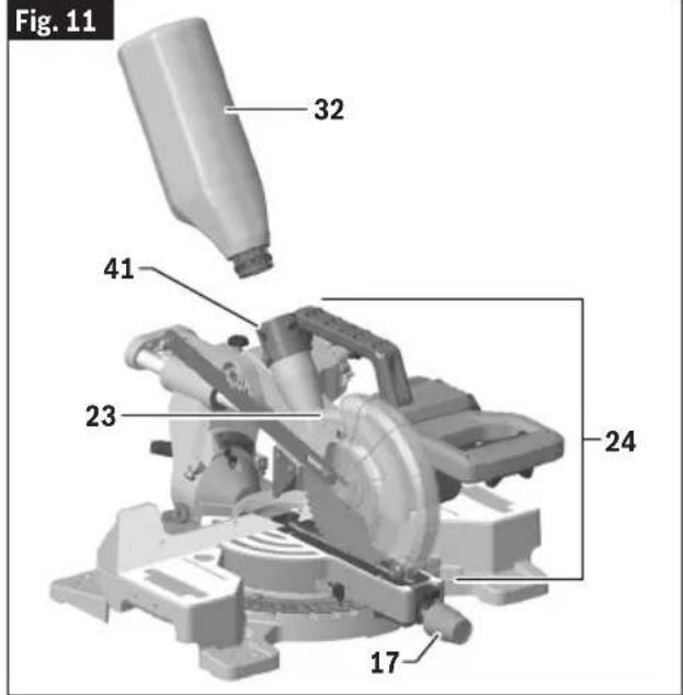
The dust collection system used on this tool is attached to the upper guard (Fig. 11, 23). This placement provides superior dust collection for the majority of cuts. Disconnect battery pack (Fig. 8, 42) before attaching, adjusting or removing any dust collection component.
Attaching the Dust Bag
Attaching and Removing Dust Bag – To attach the dust bag (Fig. 11, 32), squeeze the two red tabs together and slide the dust bag into the dust port rib.
Using and Cleaning the Dust Bag
WARNING
Be extremely careful when disposing of dust. Materials in fine parti-
cle form may be explosive. Do not throw sawdust on an open fire. Spontaneous combustion, in time, may result from the mixture of oil or water with dust particles.
Using Dust Bag – Attach the clean bag to the dust port (Fig. 11, 41).
Cleaning Dust Bag – After the dust bag is 2/3 to 3/4 full, remove it from the saw. Bring the bag to a proper container and pull open the zipper located on the bottom of the bag. Hold the bag by the coupler end and shake it vigorously until all the dust and debris fall from it. Close zipper and reattach the bag.
NOTE: Clean the bag at the end of the cutting session and before transporting or storing the saw.
text_image
Fig. 11 32 41 23 24 17Assembly
Attaching a Vacuum Cleaner/Dust Extractor
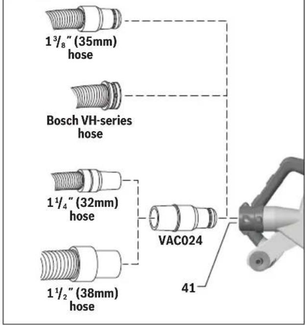
The saw's dust port (Fig. 12, 41) will accept the typical nozzles from 35 mm (13/8") vacuum cleaner hoses, and Bosch VH-Series hoses.
To connect the saw with a 1¼" (32 mm) or 1½" (38mm) hose, the Bosch VAC024 adapter can be used (sold separately).
NOTE: the sizes above indicate the hose diameters and not the nozzle diameters.
Fig. 12
text_image
1³/₈" (35mm) hose Bosch VH-series hose 1¹/₄" (32mm) hose VAC024 1¹/₂" (38mm) hose 41Attaching to Vacuum - Insert the vacuum nozzle into (or onto) the dust port (Fig. 12, 41) as far as it will go. Check to see that the vacuum hose is free from the mechanism and cutting path before reconnecting battery pack.
Adjustments
WARNING
To avoid possible injury, disconnect battery pack before performing any assembly, adjustments or repairs.
Using the Head Assembly Lock Pin
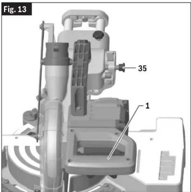
Head Assembly Lock Pin
The head assembly lock pin (Fig. 13, 35) is located on the left side of the pivot post (Fig. 2, 34). It is used to hold the saw's head assembly (Fig. 11, 24) in the DOWN position. This position prevents the head from bouncing up and down during transportation. This also makes the saw more compact for lifting and storage. This position is also required for some calibrating procedures.
text_image
Fig. 13 35 1To Engage the Head Assembly Lock Pin
- Grasp the saw's main handle (Fig. 13, 1) and press down on the head assembly (Fig. 11, 24).
- While pressing the saw head down, push in on the head assembly lock pin (Fig. 13, 35). Release the head assembly. The head will be locked in the DOWN position.
To Disengage the Head Assembly Lock Pin
- Grasp the main handle (Fig. 13, 1) and press down on the head assembly (Fig. 11, 24).
- While pressing the head down, pull out the head assembly lock pin (Fig. 13, 35). Release the lock pin, but maintain your grip on the main handle. Slowly allow the spring-loaded saw head to come up to the top of its travel and then release the handle.
Adjustments
Miter Detent System – Adjustment Procedure
Calibrating Miter Detent System
- Engage the miter detent at the 0^ position. Loosen the miter lock knob (Fig. 11, 17) 1/2 turn.
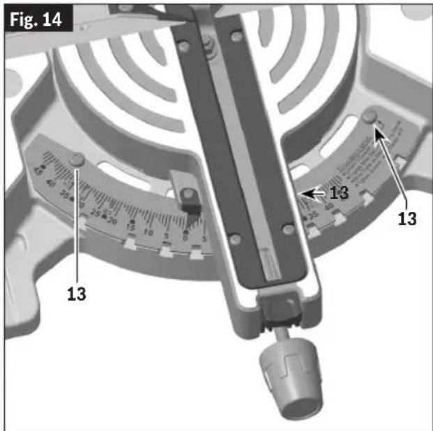
- Loosen the 3 screws holding the detent plate (Fig. 14, 13) using the Torx wrench (Fig. 7, 39).
NOTE: The third screw is underneath the table arm and can be accessed when the table is mitered more than 25^ to the left or to the right.
- Lock head assembly down using the head assembly lock pin (Fig. 11, 35).
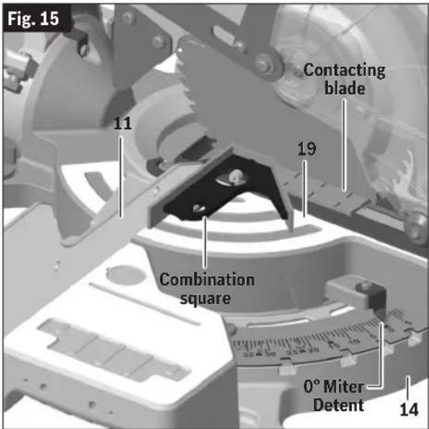
- Hold one side of a 90^ combination square against the
text_image
Fig. 14 13 13 13fence (Fig. 15, 11) and rotate the table (19) and detent plate (14) until the side of the saw blade is in full contact with the other side of the square.
- Tighten the left and right screws securing the detent plate.
- Miter the table 25° to the left or right to access the third screw and tighten it.
- Loosen and reset the miter scale pointer to the "0" position (Fig. 15).
text_image
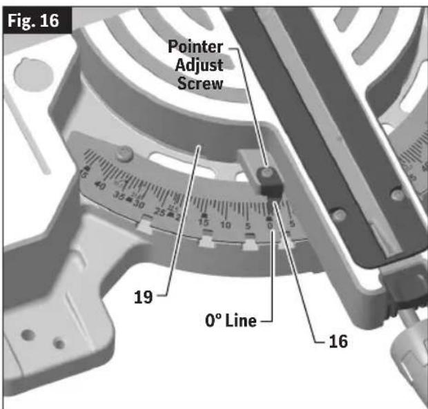
Fig. 15 11 Contacting blade 19 Combination square 0° Miter Detent 14Miter Scale Pointer Adjustment
- Rotate table (Fig. 16, 19) to 0° position and lock in place.
text_image
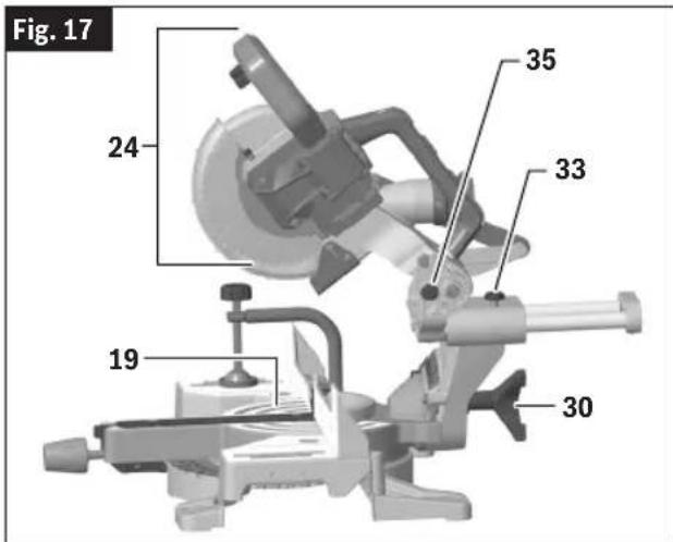
Fig. 16 Pointer Adjust Screw 19 0° Line 16- Raise the head assembly (Fig. 17, 24) to the full UP position.
- Loosen the pointer adjust screw that holds the miter scale pointer (Fig. 16, 16) in place.
- Position the pointer to align with the 0^ line. Tighten the screw.
Adjustments
0° Bevel Stop
Checking 0° Bevel Stop Setting
- Hold the saw head assembly (Fig. 17, 24) down and push in the head assembly lock pin (35) to keep the saw in the DOWN position.
text_image
Fig. 17 24 35 33 19 30-
Slide the saw head assembly (24) completely to the back and engage the slide rail lock knob (33) by tightening the knob to the right (clockwise).
-
Rotate the table to the 0^ miter position.
-
Rotate the bevel lock knob (30) clockwise to unlock the head assembly.
-
Tilt the saw head assembly (24) to the left (counterclockwise), then rotate to the right (clockwise) until you feel the stop in the vertical position. This is where the saw is currently set for 0° bevel cut.
-
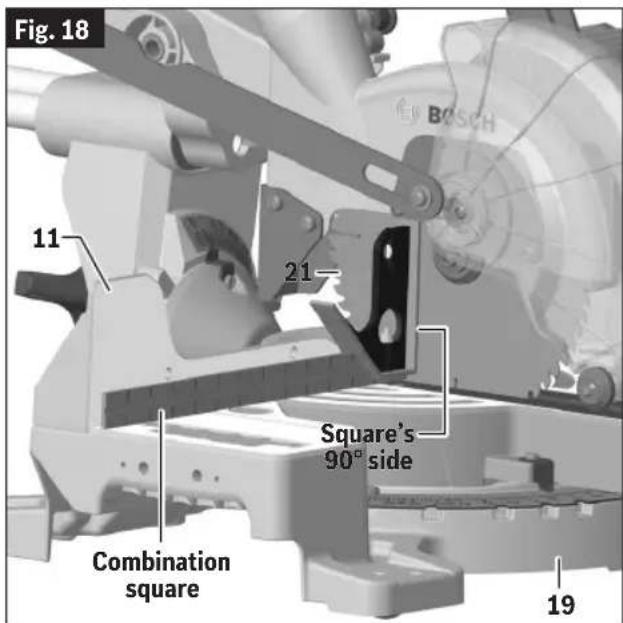
Use a combination square (Fig. 18) to check that the blade is 90^ (square) to the table (Fig. 17, 19). Place the square's ruler edge against the table and slide it to contact the blade (Fig. 18, 21) with the vertical side of the square's head.
-
Check that the saw blade's plate (21), not the saw blade's teeth, is touching the square's 90° side. If the saw blade's plate is not in full contact with the square's body 90° side, see "Adjusting 0° Bevel Stop (Blade 90° to Table)."
text_image
Fig. 18 11 21 Square's 90° side Combination square 19Adjusting 0° Bevel Stop (Blade 90° to Table)
NOTE: Use a 12 mm wrench for the adjustment.
- Lower head assembly (Fig. 17, 24) and engage head assembly lock pin (35).
- Slide the head assembly (24) completely to the back and engage the slide rail lock knob (33) by tightening the knob to the right (clockwise).
- Rotate the bevel lock knob (30) clockwise to unlock the head assembly.
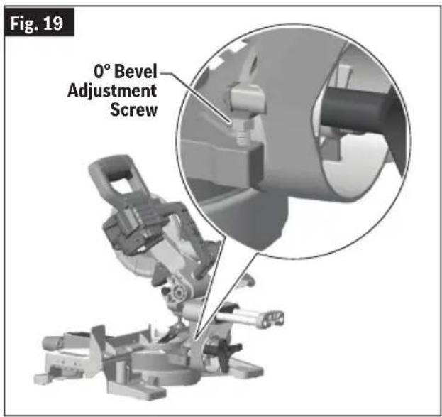
- Rotate the 0^ bevel adjustment screw (Fig. 19) clockwise to adjust the head to the right.
Rotate the 0^ bevel adjustment screw (Fig. 19) counterclockwise to adjust the head to the left.
- Follow the procedure in "Checking 0° Bevel Stop Setting" to check your modifications. If further adjustment is required, repeat the steps above.
Adjustments
text_image
Fig. 19 0° Bevel Adjustment Screw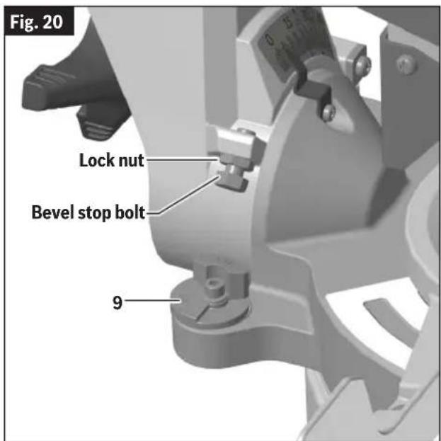
text_image
Fig. 20 Lock nut Bevel stop bolt 945° Bevel Stop
Checking 45° Bevel Stop Setting
- Hold the saw head assembly (Fig. 17, 24) down and push in the head assembly lock pin (35) to keep the saw in the DOWN position.
- Slide the saw head assembly (24) completely to the back and tighten the slide rail lock knob (33).
- Rotate the table to the 0^ miter position.
- Rotate the bevel lock knob (30) clockwise to unlock the head assembly.
- Check the position of the bevel stop indicator (Fig. 20, 9). It should be at the "45°" position.
- Tilt the saw head assembly (Fig. 17, 24) to the left (counterclockwise) until it hits the 45^ stop. This is where the saw's 45^ stop is set to make a 45^ left bevel cut.
- Use a combination square to check that the blade is 45^ to the table. Remove the rule blade from the combination square (Fig. 21). Place only the combination square's head on the saw's table with its long flat side resting on the table and its 45^ side against the tilted blade (21).
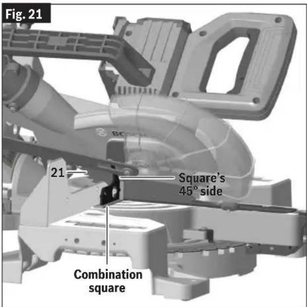
text_image
Fig. 21 21 Square's 45° side Combination squareAdjustments
- Check that only the plate of the saw blade (Fig. 21, 21), not teeth, is touching the square's 45° side. If the saw blade's plate is not in full contact with the square's 45° side, follow the procedure "Adjusting 45° Bevel Stop (Saw Blade 45° to Table)" below.
Adjusting 45° Bevel Stop (Saw Blade 45° to Table)
To avoid possible injury, remove battery (Fig. 3, 42) before performing any assembly, adjustment or repair.
NOTE: Follow instructions when checking 45^ bevel adjustment from the left or right side of miter saw.
Calibrating Blade at 45° Bevel
NOTE: Use a 10mm wrench for adjustment.
NOTE: Calibrating the bevel setting automatically calibrates the 33.9^ and 45^ .
- Lower saw head assembly (Fig. 17, 24) and engage head assembly lock pin (35).
- Slide the saw head assembly (24) completely to the back and tighten the slide rail lock knob (Fig. 22, 33) by turning it clockwise (to the right).
- Check bevel stop indicators located on the left and right side of the bevel post on the table (Fig. 20, 9). It should be at 45°.
- Rotate the bevel lock knob (Fig. 17, 30) clockwise to unlock the head assembly.
- Locate the bevel stop bolt along the left or right side of the bevel post. This bolt features a lock nut (Fig. 20).
-
Loosen the bevel stop bolt a quarter turn and then loosen the lock nut. When this is complete you will be able to adjust the bevel stop bolt by hand.
-
Rotate the bevel stop bolt clockwise to adjust the head to the lift.
-
Rotate the bevel stop bolt counter-clockwise to adjust the head to the right.
-
Follow the procedure in "Checking 45° Bevel Stop Setting" on page 25 to check your modifications. If further adjustment is required, repeat the steps above.
-
Once satisfactory, lock the bevel at 45^ by rotating the bevel lock knob (Fig. 17, 30) counterclockwise.
-
Finger tighten the lock nut (Fig. 20) in place. Once secured, tighten with wrench.
Transporting and Mounting
WARNING
To avoid possible injury, disconnect battery pack before performing any assembly, adjustments or repairs.
Lifting the Saw
WARNING
To avoid injury, follow all statements identified below by the BUL-
LET (•) symbol.
- Never lift the saw by gripping any of the sliding mechanism parts. The saw may move and cause severe injuries to your fingers or hands.
• To avoid back injury, hold the tool close to your body when lifting. Bend your knees so you can lift with your legs, not your back. Lifting the saw from the back is the preferred method. This will tip the tool toward your body. - Never lift tool by holding switch handle. This may cause serious damage.
- Place the saw on a firm, level surface where there is plenty of room for handling and properly supporting the workpiece.
ONLY lift this saw by the cast-in carry handles at each side of the bottom of the base (Fig. 22, 12) or by the main carry handle (4).
- Slide the saw head assembly completely to the front and tighten the slide rail lock knob (Fig. 22, 33) by turning it clockwise (to the right).
Lift the Saw by the Cast-in Carry Handles
With the saw facing you and the head mitered to 47° Right, the saw head assembly (Fig. 17, 24) locked down, and the head in the forward position with the slide rail knob (Fig. 22, 33) tightened, grip both cast in carry handles (12) or the main carry handle (4). Continue to lift and transport comfortably.
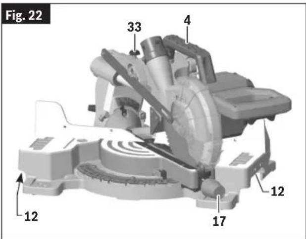
text_image
Fig. 22 33 4 12 17 12Preparing to Lift the Saw
- Set bevel angle at 0^ and lock the bevel by rotating the bevel lock knob (Fig. 17, 30) counterclockwise.
- Rotate the table to either 47^ or 0^ and lock into place using the miter lock knob (Fig. 22, 17).
- Lock the saw head assembly (Fig. 17, 24) in the DOWN position with the head assembly lock pin (35).
Transporting and Mounting
Mounting Applications
WARNING
Be certain the miter saw is mount-ed or placed on a level, firm work
surface before using. A level and firm work surface reduces the risk of the miter saw becoming unstable.
Workbench Permanent Attachment
- Each of the four mounting holes (Fig. 23) in the tool mounting pads (10) should be bolted securely using 5/16" (M8) bolts, lock washers and hex nuts (not included).
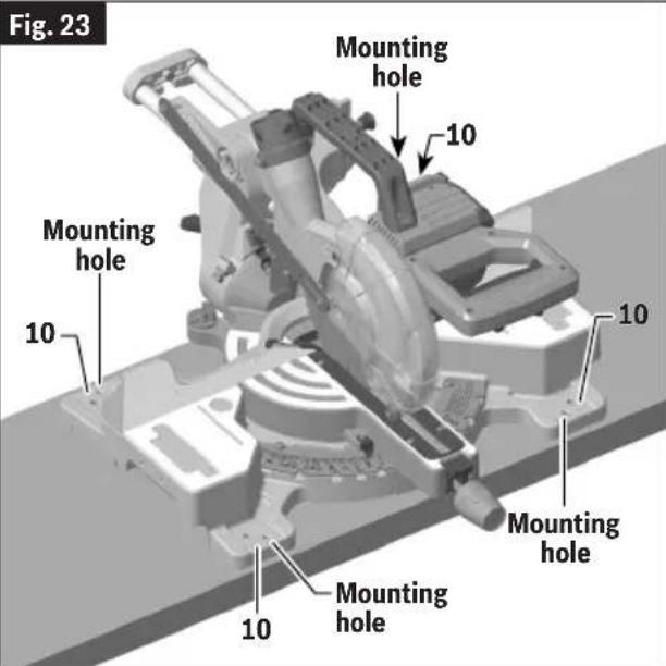
text_image
Fig. 23 Mounting hole 10 Mounting hole 10 Mounting hole 10 Mounting hole 10- Locate and mark where the saw is to be mounted.
- Drill four 5/16" (8mm) diameter holes through workbench.
- Place the miter saw on the workbench, aligning holes in base with holes drilled in workbench. Install bolts, lock washers and hex nuts.
Alternate Attachment
CAUTION
Be careful not to over-drive nail or over-torque the bolt. This could crack
foot or damage base.
The smaller mounting holes at each corner can be used for nails or longer drywall screws.
The supporting surface where the saw is to be mounted should be examined carefully after mounting to ensure that no movement can occur during use. If any tipping or walking is noted, secure the workbench or stand before operating the miter saw.
Temporary Mounting Using Clamps
- If necessary, clamp the miter saw to a workbench or table top.
- Place two or more "C" clamps on the clamping areas (Fig. 24) and secure. There are clamping areas at all four corners of the saw.
- Mounting with clamps may prevent access to some wide miter angles.
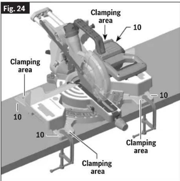
text_image
Fig. 24 Clamping area 10 Clamping area 10 10 Clamping area Clamping areaPreparing for Saw Operations
WARNING
To avoid possible injury, disconnect battery pack before performing any assembly, adjustments or repairs.
Switch Activation
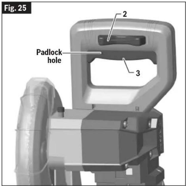
For safety, the power switch (Fig. 25, 3) is designed to prevent accidental starts. To operate safety switch, slide the switch "Lock-OFF" release buttons (2) with either thumb to disengage the lock, then pull the power switch (3) trigger and release the switch "Lock-OFF" release button. When the power switch trigger is released, the switch "Lock-OFF" release button will engage the power switch trigger automatically, and the lever will no longer operate until either "Lock-Off" release button is engaged again.
NOTE: Padlock hole (Fig. 25) can accommodate a padlock with a long shackle of up to 5/16" (8mm) in diameter (not provided with miter saw) to prevent unauthorized use.
Built-in LED Light
Your tool is equipped with a powerful LED light for better vis-
text_image
Fig. 25 Padlock hole 2 3ibility when cutting. The light has the ability to turn on when only partially depressing the trigger (Fig. 25, 3). The light will stay on for 30 seconds after the trigger has been released. This allows the cut to be more visible.
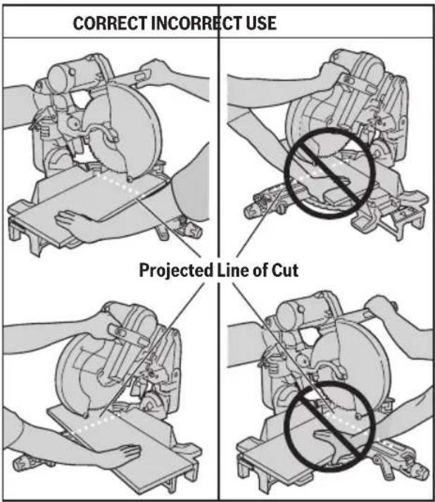
Body and Hand Position
WARNING
Position your body and hands properly to make cutting easier
and safer. Failure to follow all instructions, identified below by bullet (•) symbols, may result in serious personal injury. (See Fig. 26 below.)
- Never place hands near cutting area. Keep hands and arms outside the "NO HANDS" zone.
Fig. 26
text_image
CORRECT INCORRECT USE Projected Line of CutNo Hands Zone
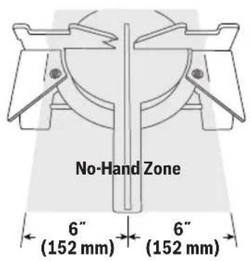
The "No Hands Zone" is an area 6 inches (152mm) wide on left and right side of the blade cutting path. Portion of the fence in this area also is considered a part of the "No Hands Zone."
The "No Hands Zone" for zero miter and zero bevel cuts is marked on the tool with lines and "No Hands" symbols (Fig. 27).
Preparing for Saw Operations
Fig. 27
text_image
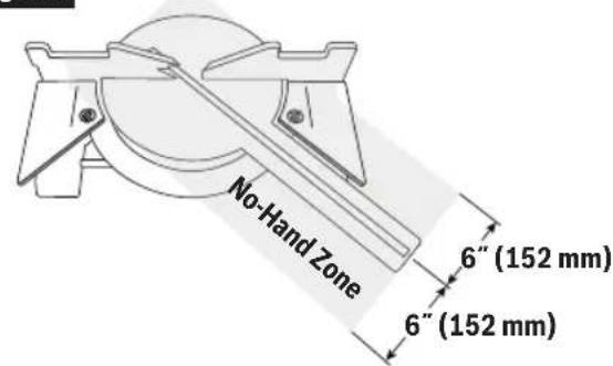
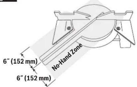
No-Hand Zone 6" (152 mm) 6" (152 mm)The "No Hands Zone" for all slide and miter right cuts (Fig. 28).
Fig. 28
text_image
No-Hand Zone 6" (152 mm) 6" (152 mm)The "No Hands Zone" for all slide and miter left cuts (Fig. 29).
Fig. 29
text_image
6" (152 mm) 6" (152 mm) No-Hand ZoneWith all bevel cuts the "No Hands Zone" extends vertically up to the bottom of the upper guard when the head assembly is in the lowest cut position (Fig. 30).
Fig. 30
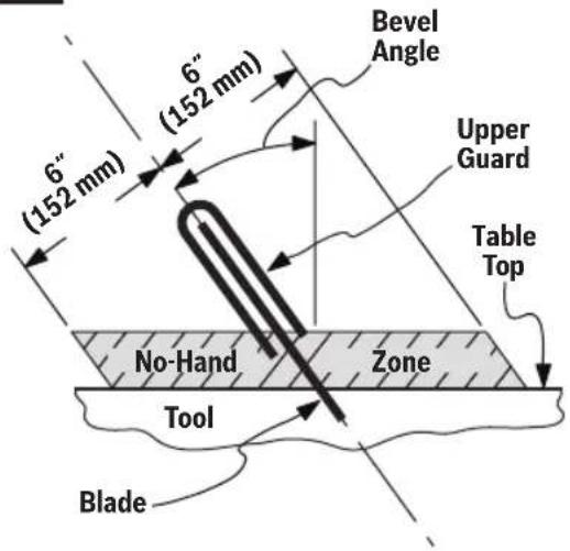
text_image
Bevel Angle 6" (152 mm) 6" (152 mm) Upper Guard Table Top No-Hand Zone Tool BladeUse fence outside No Hands Zone
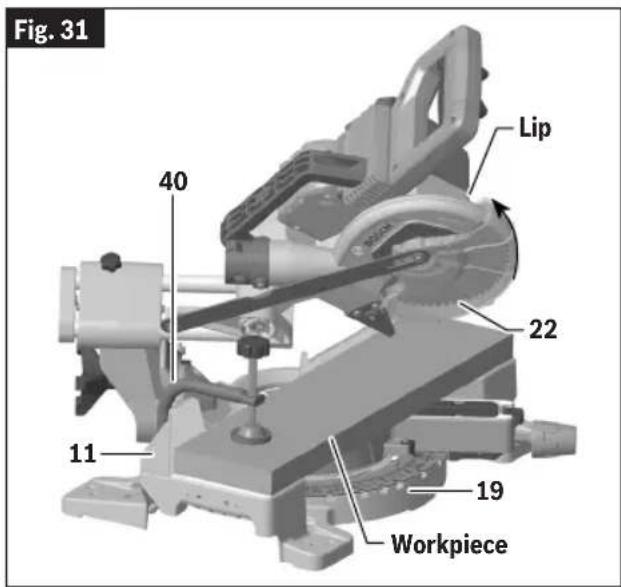
Use fence (Fig. 31, 11) and additional workpiece supports to properly support the workpiece and hold or clamp it outside of the "No Hands Zone" (Fig. 27, Fig. 28, Fig. 29, Fig. 30).
Workpiece can be held against table (Fig. 31, 19) and fence (11) by hand only outside of the "No Hands Zone."
- Hold workpiece firmly against table and fence to prevent movement.
- Keep hands in position until trigger has been released and blade has completely stopped.
- Never place hands on mechanism components.
- Keep feet firmly on the floor and maintain proper balance.
- Follow the miter arm when mitering left or right. Stand slightly to the side of the saw blade.
Preparing for Saw Operations
text_image
Fig. 31 40 Lip 22 11 19 WorkpieceDry Run
WARNING Be aware of the path of the saw blade. Make a dry run with the battery pack disconnected and the saw switched OFF by conducting a simulated cutting cycle, and observe the projected path of the saw blade. Keep hands out of the path of saw blade.
It is important to know where the blade will intersect with the workpiece during cutting operations. Always perform the simulated cutting sequence with the battery pack disconnected and the power tool switched OFF to gain an understanding of the projected path of the saw blade. Mentally note where the path of the saw blade will fall and set up your work to keep your hands and arms out of the path of the spinning blade. Adjust your clamps and fences so that the smooth lower guard and cutting action are not interfered with during cutting operation.
Lower Guard
WARNING The lower guard (Fig. 31, 22) may not automatically open under certain cutting conditions; for example, when trying to cut workpieces that are near the maximum cutting height capacity. Under these conditions or during the blade travel motion of cut, the workpiece can stop the lower guard movement before the downward motion of the arm could pre-open the lower guard.
If this occurs:
Workpiece must be securely clamped with clamp (Fig. 31 and Fig. 32, 40). This frees a hand to raise the lower guard (22) by the lip just enough to clear the workpiece.
Start the saw and begin your cut. Once you have cleared the position where the lower guard may bind, release the guard and it will continue to operate automatically as you cut.
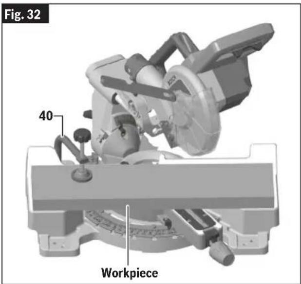
text_image
Fig. 32 40 WorkpiecePreparing for Saw Operations
Workpiece Support
Clamps
WARNING There may be extreme compound cuts where a clamp cannot be used. Support workpiece with your hand outside the "No Hands" zone. Do not try to cut short pieces that cannot be clamped and cause your hand to be in the "No Hands" zone.
WARNING Be aware of the path of the saw blade. Make a dry run with the battery pack disconnected and the saw switched OFF by conducting a simulated cutting cycle, and observe the projected path of the saw blade. Keep hands at least six (6) inches (152mm) away from the projected path of the saw blade.
Using the Workpiece Clamp – This clamp (Fig. 32, 40) easily secures a workpiece to the table or base.
- Insert the clamp's knurled bar down into a clamp post hole (Fig. 3, 38). There are two post holes located in the base behind the fence (Fig. 3). The knurled end must be in the post at least 1/2" (13mm).
- Slide the clamp down until its rubber foot contacts the workpiece.
- Adjust the clamp height so it does not touch the fence.
- Rotate the clamp's knob until the workpiece is firmly held in place.
- Move saw head up and down and forward and back to be sure it clears the clamp.
Other Clamps – Other hold-down devices such as C-clamps can be used to hold the workpiece firmly against the table (Fig. 31, 19) and the fence (11). Make sure the clamps are clear of the cutting path.
Long Workpiece Support
WARNING Long workpieces have a tendency to tip over unless clamped down and properly supported from underneath.
WARNING Do not use another person as a substitute for a table extension or as
additional support. Unstable support for the workpiece can cause the blade to bind or the workpiece to shift during the cutting operation, causing you to contact the spinning blade.
Additional Workpiece Support
WARNING Always ensure that supporting surfaces are able to properly support the workpiece and allow for secure holding by hand outside of the "No Hand Zone", or clamping with a clamp inside or outside of the "No Hand Zone." (See "Body and Hand Position" on page 29 for the "No Hand Zone" and the appropriate hand positions.)
WARNING Be aware of the path of the saw blade. Make a dry run with the battery pack disconnected and the saw switched OFF by conducting a simulated cutting cycle, and observe the projected path of the saw blade. Keep hands at least six (6) inches (152mm) away from the projected path of the saw blade.
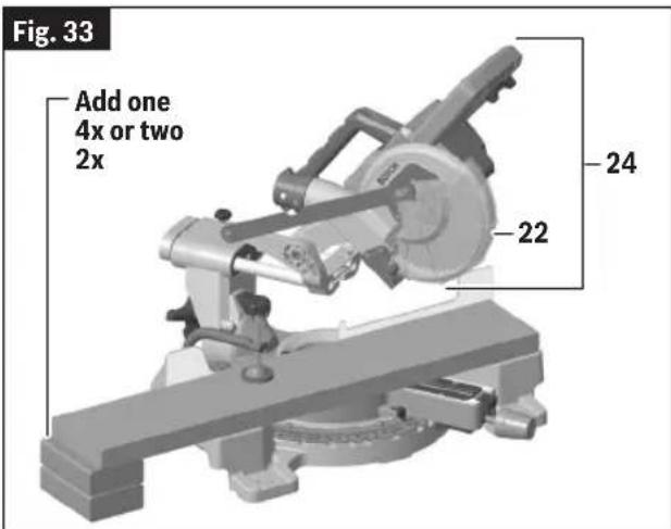
Blocks – Long pieces need extra support. The base height (3-1/2" / 89mm) is designed to match the standard lumber of one 4x or two 2x. Boards of these thicknesses can be used to create auxiliary support extensions for long workpieces (Fig. 33).
text_image
Fig. 33 Add one 4x or two 2x 24 22Preparing for Saw Operations
Making an Auxiliary Fence
WARNING
Check for interference between auxiliary fence and saw head com-
ponents by performing a dry run. Fence interference can prevent proper saw operation and cause injury and/or tool damage.
WARNING
Be aware of the path of the saw blade. Make a dry run with the saw
OFF by conducting a simulated cutting cycle, and observe the projected path of the saw blade. Keep hands at least six (6) inches (152mm) away from the projected path of the saw blade.
Certain types of molding need a fence face extension because of the size and position of the workpiece. Holes are provided in the fence to attach an auxiliary fence. Only use the auxiliary fence with the saw in the 0° bevel position.
- To create an auxiliary fence (Fig. 34), place a piece of wood against the fence (Fig. 31, 11). Wood can have a maximum height of 3-1/4" (83mm). Check that auxiliary fence assembly (Fig. 34) does not interfere with the saw head assembly (Fig. 33, 24).
- Mark the locations of the support holes on the wood from the back side of the fence.
- Drill and countersink the holes on the front of the support board.
- To fasten from front of fence: Attach (each) auxiliary fence using two (2) 3/16" (M5) flat head machine screws (Fig. 34). With 3/4" (19mm) auxiliary fence, use 1-1/2" (38mm) long screws. Secure behind metal fence with washer and machine nuts.
To fasten from back of fence: With 3/4" (19mm) auxiliary fence, use 1/4" (M6) round head wood screws (3/4"/20mm long). Drill four pilot holes through auxiliary fence and run screws from rear of metal fence.
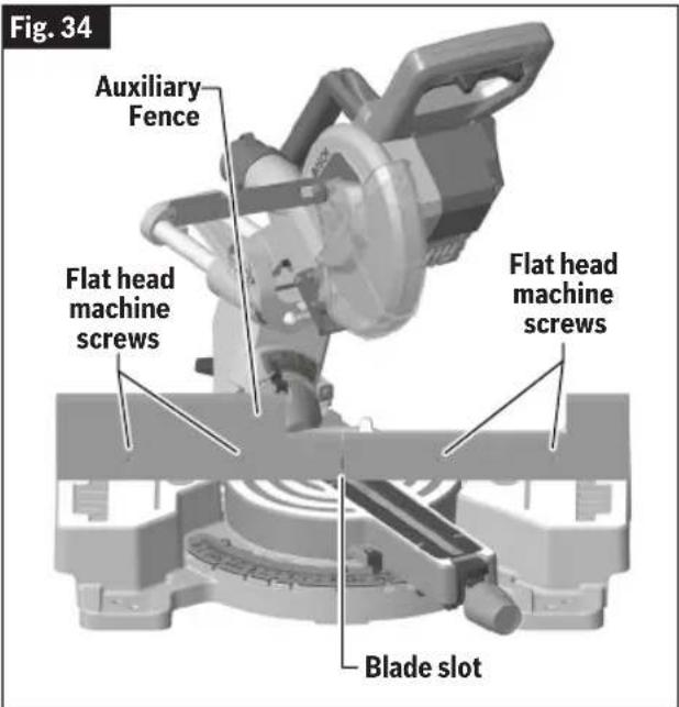
text_image
Fig. 34 Auxiliary Fence Flat head machine screws Flat head machine screws Blade slot- Make a full depth cut to create the blade slot. Check for interference between the auxiliary fence (Fig. 34) and the lower blade guard (Fig. 33, 22). Make adjustments as necessary.
- For best splinter-free cuts, use the chop cut method.
- When making slide cuts, the center must be notched out per pattern (Fig. 35).
Fig. 35

text_image
8-1/2" (216mm) 10-1/2" (267mm) 2-1/2" (64mm) 7/8" (22mm) Right Side 1-1/2" (38mm) 4 mounting holes Left Side 3-1/4" (83mm) 2-3/4" (70mm) 2-3/4" (70mm) 7-1/8" (181mm) 7-1/8" (181mm) 21-1/2" (546mm)Tall Auxiliary Wood Fence - 3/4" (19mm) Thick
Saw Operations
Brake Operation
WARNING
The brake action of this saw is not intended as a safety feature. Remember to let the saw blade come to a complete stop before raising the blade from the workpiece. As always, the guard system is your best protection against unintentional contact with a spinning saw blade. NEVER wedge open or defeat the closing action of the lower guard.
WARNING
Know the charge state of your battery. The electric braking action is initiated ONLY by the release of the trigger switch and in a tool that has power available. When electrical power is lost due to a discharged battery or other causes, the electric brake will not operate, and the motor will gradually slow down. Unexpected run-down time may cause property damage and/or personal injury.
Your saw is equipped with an automatic electric brake which is designed to stop the blade from spinning in about five (5) seconds after you release the trigger switch. It is useful when making certain cuts in wood where a coasting blade would result in a wide, imprecise cut.
Braking starts once the power is turned off.
The brake requires a charged battery to function. Stopping time will vary depending on, among other factors, saw blade used, and number of actuations. The electric brake of your miter saw has been designed for a high degree of reliability, but unexpected circumstances such as contamination or failure of the motor's components can cause the brake to not activate. If the tool operates but the brake does not consistently stop the blade in about 5 seconds, DO NOT use the miter saw and have it serviced by a Bosch Factory Service Center or Bosch authorized service facility.
Using the Miter Lock Knob
- Loosen the miter lock knob (Fig. 36, 17).
text_image
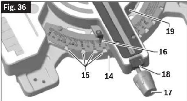
Fig. 36 19 16 15 14 18 17-
While holding the knob in your palm, push the miter detent button, rotate table left or right to needed miter angle, and release the button.
-
Once at the correct angle, tighten the knob by rotating it clockwise.
NOTE: It is recommended to tighten the miter lock knob before all cuts. It is required to tighten the knob before cutting at any angle between detent engagements or when the miter detent system is in use.
Using Miter Detent System
-
Loosen the miter lock knob (Fig. 36, 17) about 1/2 turn.
-
Grip the miter lock knob (17), and then push the miter detent button (18) down with your thumb and push until the button is out from the detent plate (14).
-
While gripping the miter lock knob (17) and miter detent button (18), rotate the saw's table (19). Stop table rotation at the desired angle as indicated by the miter scale pointer (16).
-
Release the button into a detent (15) in the detent plate (14) or at an angle between detents. If close to a detent, use the detent override feature.
-
Tighten the miter lock knob (17) by rotating it clockwise before cutting.
NOTE: It is recommended to tighten the miter lock knob (17) before all cuts. It is required to tighten the knob before cutting at any angle between detents (15).
Saw Operations
Chop Cuts
What's a Chop Cut?
- A “chop cut” is a cross-cut made when the saw is held to the rearmost position and is operated like a conventional (non-sliding) miter saw. Using the chop cut method lowers the cross-cutting capacity. However, many users prefer this method because it is quicker when making repeat cuts. This method can also produce more accurate cuts because the saw head is locked in the retracted position.
- This saw has bevel angle stops that accurately stop at critical angles: 45° Left/Right and 0° Right. It comes factory-set and should not require adjustment. However, after extensive use or if the tool has received a hard impact, it may require an adjustment.
- A chop cut can cut pieces with a width of 3-3/4" (95mm) or less.
Preparing for Chop Cut
WARNING
Use clamping position that does not interfere with operation. Be-
fore switching "ON", lower head assembly to make sure clamp clears guard and head assembly.
WARNING
Be aware of the path of the saw blade. Make a dry run with the bat-
tery pack disconnected and the saw switched OFF by conducting a simulated cutting cycle, and observe the projected path of the saw blade. Keep hands at least six (6) inches (152mm) away from the projected path of the saw blade.
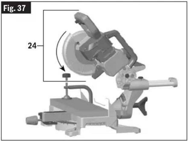
- With the saw head assembly (Fig. 37, 24) in the UP position, push it back over the fence to the rear.
- Turn the slide rail lock knob (Fig. 38, 33) clockwise to lock it.
- Properly position your workpiece and clamp it firmly to the table (Fig. 37, 19), the fence (11), or both.
text_image
Fig. 37 24-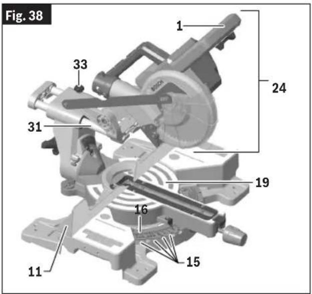
text_image
Fig. 38 1 24 33 31 19 16 15 11Making a Chop Cut
- Activate the switch (Fig. 1, 3), then fully lower the saw head assembly (Fig. 37, 24) to make the cut.
- Hold the saw head assembly down until the blade comes to a complete stop. Return the the saw head assembly to the UP position. Remove workpiece.
Saw Operations
Slide Cuts
What's a Slide Cut?
WARNING
NEVER pull the saw toward you during a cut. The blade can suddenly climb up on top of the workpiece and force itself toward you.
- A "slide cut" is made with the head assembly (Fig. 38, 24) unlocked and able to move away from the fence (11). This movement is supported and precisely controlled by the slide system (31). The maximum cross-cutting capacity is utilized by using this method.
- A slide cut is best used for cross-cutting workpieces wider than can be done with a chop cut – pieces wider than 3-3/4" (95mm) and up to a maximum width of 8-1/4" (210mm) across.
Preparing for Slide Cut
WARNING
Use a clamping position that does not interfere with operation. Before switching "ON," lower head assembly (Fig. 38, 24) to make sure clamp clears guard and head assembly.
WARNING
Be aware of the path of the saw blade. Make a dry run with the battery pack disconnected and the saw switched OFF by conducting a simulated cutting cycle, and observe the projected path of the saw blade. Keep hands at least six (6) inches (152mm) away from the projected path of the saw blade.
- Place the saw head assembly (Fig. 38, 24) in the UP position.
- Loosen the slide rail lock knob (33) by turning it counterclockwise (to the left).
- With the head assembly (24) in the UP position, move it fully to the front and back to check that the slide system (31) moves smoothly.
- Properly position your workpiece and clamp it firmly to the table (19), the fence (11), or both.
Making a Slide Cut
- With the head assembly (Fig. 38, 24) in the UP position, grasp the main handle (1) and move the head assembly fully to the front and away from the fence (11).
- Activate the switch (Fig. 1, 3), and then fully lower the saw head assembly (Fig. 38, 24) (Fig. 39, actions 1 and 2). On larger pieces, this action may also start the cut.
- Push down and back so the saw head assembly moves
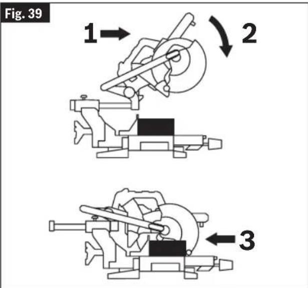
text_image
Fig. 39 1 → 2 3toward the fence (Fig. 38, 11) and to the full rear position until you complete the cut (Fig. 39, action 3).
NOTE: If high resistance is felt, do not apply excessive force – stop cutting, wait until blade stops and investigate problem.
- Hold the saw head down until the blade comes to a complete stop. Return the saw head to the UP position and remove the workpiece.
Saw Operations
Miter Cuts
What's a Miter Cut?
- A "miter cut" is a cross-cut made with the blade perpendicular to the horizontal table (Fig. 38, 19). The blade is not tilted and the bevel pointers are both on the 0^ lines.
- Miter cuts can be made at any angle across a workpiece within this saw's range, from 47^ left to 47^ right.
- The miter scale (16) shows the angle of the blade relative to the saw's fence (11). The miter pointer is attached to the table (19) and indicates the saw's miter position before the cut is made.
- Nine positive detents (15) are provided for fast and accurate preset miter angles – locations are at 45°, 31.6°, 22.5°, 15° left and right, and center at 0°.
- The crown molding detents on the left and right are at 31.6° for compound cutting 38° “spring angle” crown molding lying flat on the table. See “Cutting Crown Molding” on page 42.
- A miter cut can be made either as a chop cut or slide cut, depending on the width of the workpiece.
Crown molding information – There are miter position settings for compound-cutting crown molding flat on the table. Crown molding with 38^ “spring angle” uses the 31.6 setting (with detent) and crown molding with 45^ “spring angle” uses the 35.3 setting.
NOTE: This cutting method also requires that specific bevel angles are set. See "Cutting Crown Molding" on page 42.
Reading the Miter Scale
The miter scale (Fig. 38, 16 and Fig. 40) used on this saw includes several scales of information to help the user accurately preset this saw before making the cuts.
Fig. 40
Miter scale information
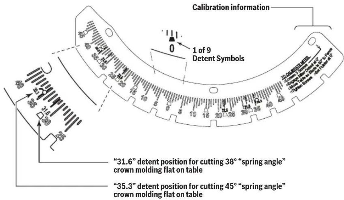
text_image
Calibration information 1 of 9 Detent Symbols "31.6" detent position for cutting 38° "spring angle" crown molding flat on table "35.3" detent position for cutting 45° "spring angle" crown molding flat on tableSaw Operations
Setting Saw to Make a Miter Cut

Use a clamping position that does not interfere with operation. Before switching ON, lower head assembly to make sure clamp clears guard and head assembly.
- See "Using Miter Detent System" on page 34.
- Loosen the miter lock knob (Fig. 41, 17). Push miter detent button (18) and move the saw to the desired angle, using either the detents (15) or the miter scale (16). Tighten miter lock knob (17).
- Properly position workpiece. Make sure workpiece is clamped firmly against the table (19) with a clamp (40)
Fig. 41
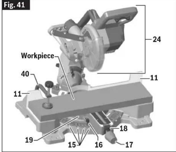
text_image
Fig. 41 Workpiece 24 40 11 11 18 19 15 16 17or against the fence with a C-clamp (Fig. 41).
- Follow either the procedure "Chop Cuts" on page 35 or "Slide Cuts" on page 36.
- Wait until saw blade comes to a complete stop before returning head assembly (Fig. 41, 24) to the raised position and then remove workpiece.
Bevel Cuts
What's a Bevel Cut?
A "bevel cut" is a cross-cut made with the blade perpendicular to the fence (Fig. 41, 11) and with the table (19) set at 0^ miter. The blade can be tilted to any angle within the saw's range: 47^ left and 47^ right from the vertical.
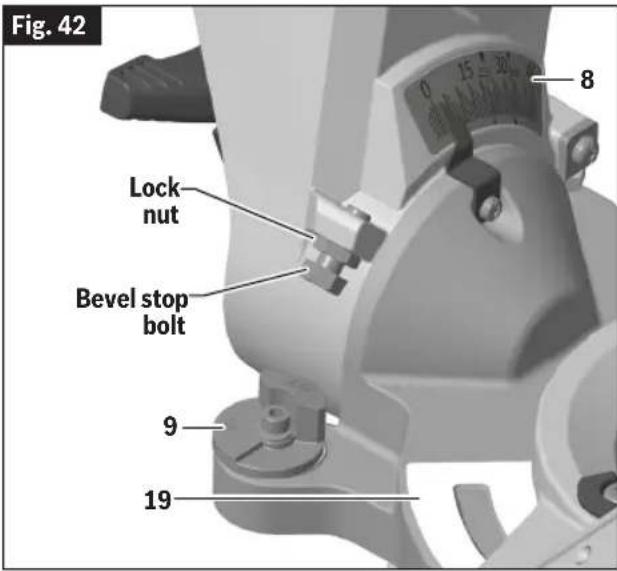
The bevel scale is sized and positioned for easy reading (Fig. 42, 8 and Fig. 43). The bevel lock knob (Fig. 44, 30) is to lock and unlock the various settings.
Rotating bevel stop indicators (Fig. 42 and Fig. 44, 9) allow
text_image
Fig. 42 Lock nut Bevel stop bolt 9 19 8you to set the most common bevel stops: 33.9°, 45° and 47° Left (Fig. 43). The 33.9° bevel stop is for cutting 38° "spring angle" crown molding flat on the table. For more information, see "Compound Cuts" on page 40.
Saw Operations
Fig. 43
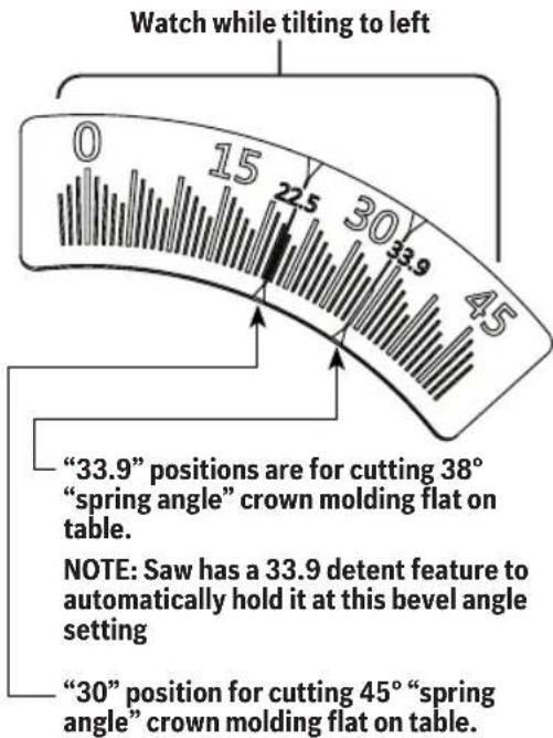
Bevel scale information
text_image
Watch while tilting to left 0 15 22.5 30 33.9 45 "33.9" positions are for cutting 38° "spring angle" crown molding flat on table. NOTE: Saw has a 33.9 detent feature to automatically hold it at this bevel angle setting "30" position for cutting 45° "spring angle" crown molding flat on table.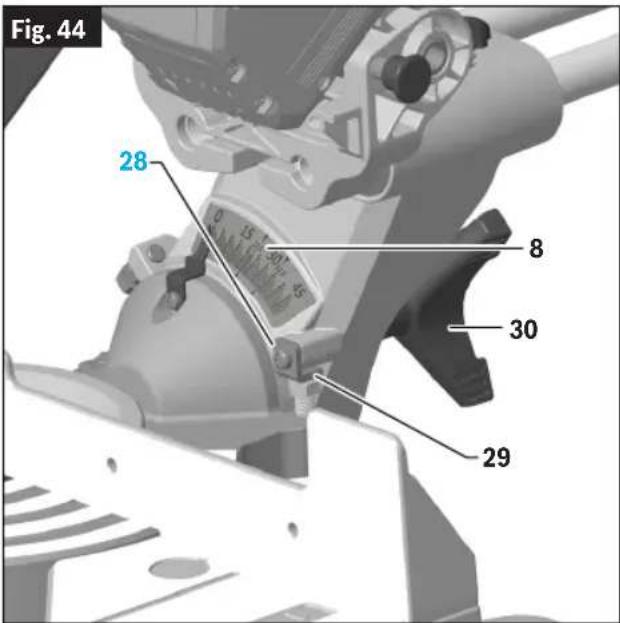
text_image
Fig. 44 28 15 30 8 30 29Setting Saw to Make a Bevel Cut
- With one hand, rotate the bevel lock knob (Fig. 44, 30) clockwise to unlock the head assembly.
- Adjust your left or right bevel stop indicator (9) to one of the three pre-set locations, 33.9°, 45°, 47°, or tilt the head assembly (Fig. 41, 24) until you reach the desired angle on your bevel scale (Fig. 43 and Fig. 44, 8).
NOTE: To make a -2° bevel undercut, follow the procedure "Using the -2° Bevel Undercut Feature" below, then return here.
- Lock the bevel by rotating the bevel lock knob (30) counterclockwise.
- Follow either the procedure "Chop Cuts" on page 35 or "Slide Cuts" on page 36.
Using the -2° Bevel Undercut Feature
Perform the following steps to use the -2^ bevel undercut feature.
- Tilt the head assembly to the left.
- Use the Torx wrench provided with the tool (Fig. 7, 39) to loosen the screw (Fig. 44, 28) securing the -2° bevel undercut plate (29).
- Rotate the -2^ bevel undercut plate (29) counterclockwise.
- To secure the -2° bevel undercut plate (29) in place, use the Torx wrench provided with the tool (Fig. 7, 39) to tighten the screw.
-
Tilt the saw head to -2^ to the right.
-
To disengage the -2^ bevel undercut plate (29), loosen the screw (Fig. 44) securing the plate, and rotate the plate clockwise.
Saw Operations
Compound Cuts
WARNING
Before sawing, always check that there is no interference between moving and stationary parts of the saw. These miter and bevel combinations may result in interference between the sliding and stationary parts of the saw or between the sliding parts and the work piece.
What's a Compound Cut?
- A “compound cut” is a single cross-cut made with the saw blade preset at two angles combining a miter angle (relative to the vertical fence) with a bevel angle (relative to the horizontal table).
- Miter angles will be with the table rotated away from 0^ and within this saw's range from 47^ left to 47^ right.
- A bevel angle is when the blade is tilted away from 0^ . This saw's range is from 47^ left to 2^ right.
- A compound cut can be made as a chop cut or a slide cut. (See "Chop Cuts" on page 35 or "Slide Cuts" on page 36.)
Making a Compound Cut
WARNING
Use clamping position that does not interfere with operation. Before switching ON, lower head assembly to make sure clamp clears guard and head assembly.
WARNING
Be aware of the path of the saw blade. Make a dry run with the battery pack disconnected and the saw switched OFF by conducting a simulated cutting cycle, and observe the projected path of the saw blade. Keep hands at least six (6) inches (152mm) away from the projected path of the saw blade.
Follow these instructions for making your compound cut:
- Properly position workpiece. Make sure workpiece is clamped firmly against the table (Fig. 45, 19) or the fence (11).
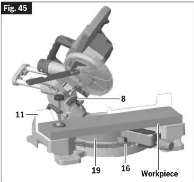
text_image
Fig. 45 8 11 19 16 Workpiece- Set miter angles for miter cuts according to the instructions in "Miter Cuts" on page 37, and set bevel angles for bevel cuts according to the instructions in "Bevel Cuts" on page 38.
- Follow the procedures "Chop Cuts" on page 35 or "Slide Cuts" on page 36.
- Wait until saw blade comes to a complete stop before returning head assembly (Fig. 41, 24) to the raised position and then remove workpiece.
Cutting crown molding flat on the table (19) requires compound cuts. See "Cutting Crown Molding" on page 42.
Saw Operations
Cutting Base Molding
Base molding can be cut vertical against fence or flat on the table. The maximum size that can be vertical on the fence is 3-3/4" (95mm), flat on table is 8-1/4" (210mm).
See the “Base Molding Cutting Instructions” table below for helpful hints on cutting base molding for corners that have 90^ angles.
Cutting base molding can be done either as a chop cut or a slide cut depending on the size of the workpiece. (See “Chop Cuts” on page 35 or “Slide Cuts” on page 36.)
| Base Molding Cutting Instructions | |||||
| LOCATION OFMOLDING ON SAW → | Molding in Vertical Position: Back of molding is against the fence | Molding in Horizontal Position: Back of molding is flat on the table | |||
| Bevel Angle Bevel = 0° Bevel = 45° | |||||
| Molding piece being cut To left of corner | To right of corner | To left of corner | To right of corner | ||
| Inside corner of wall | Miter Angle Left at 45° Right at 45° | 0° 0° | |||
| Position of molding on saw | Bottom against table | Bottom against table | Top against fence | Top against fence | |
 | Finished side | Keep left side of cut | Keep right side of cut | Keep left side of cut | Keep left side of cut |
| Outside corner of wall | Miter Angle Right at 45° Left at 45° | 0° 0° | |||
| Position of molding on saw | Bottom against table | Bottom against table | Bottom against fence | Top against fence | |
 | Finished side | Keep left side of cut | Keep right side of cut | Keep right side of cut | Keep right side of cut |
Saw Operations
Cutting Crown Molding
Crown molding cuts must be positioned properly to fit exactly.
There are two ways to cut crown molding: flat on table or angled to table and fence.
See the "Miter and Bevel Settings for Standard Crown Molding Cuts (When Workpiece Angled Against Fence)" table below for helpful hints on cutting crown molding for corners that have 90^ angles.
Crown molding's "spring angle" is the angle between the back of the molding and the bottom flat surface that fits against the wall.
This miter saw has special miter detents at 31.6^ and bevel detents at 33.9^ . These detents allow you to easily position most crown molding flat on the table and make precise cuts for 90^ corners.
NOTE: These detents cannot be used with 45^ crown molding. These detents are only for use with crown molding that has a 38^ “spring angle.”
Also see "Crown Molding Lying Flat on Table" on page 44 for miter and bevel angles for cutting crown molding that has 38^ and 45^ spring angles. The table "Miter and Bevel Settings
for Standard Crown Molding Cuts (When Workpiece Angled Against Fence)" below lists the exact miter and bevel settings required for a wide range of corner angles.
Even though these angles are standards, most rooms do not have angles of exactly 90^ ; therefore, you will need to fine-tune your settings.
The optional Bosch GAM 220 MF and GAM 270 MFL Digital Anglefinder/Protractors measure spring angles and corner angles, then automatically determine the exact miter and bevel settings necessary to make each crown molding cut fit perfectly.
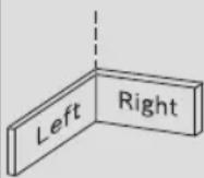
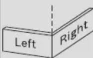
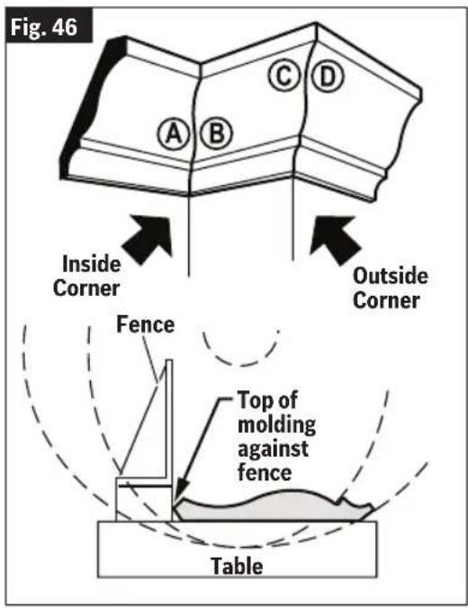
Miter and Bevel Settings for Standard Crown Molding Cuts (When Workpiece Angled Against Fence)
| Any Crown Molding Up To 6” (152mm) | ||
| NOTE: Always place bottom edge against fence | Miter (Table) Setting | Bevel (Tilt) Setting |
| Inside Corner | ||
| Left end (Fig. 46, A) Use the left end of the cut | 45° Right 0° | Left |
| Right end (Fig. 46, B) Use the right end of the cut | 45° Left 0° | Right |
| Outside Corner | ||
| Left end (Fig. 46, C) Use the left end of the cut | 45° Left 0° | Right |
| Right end (Fig. 46, D) Use the right end of the cut | 45° Right 0° | Left |
Assumptions: Molding is milled consistently. Corner is 90°. For other corner angles, divide actual measurement by 2.
text_image
Fig. 46 A B C D Inside Corner Outside Corner Fence Top of molding against fence TableSaw Operations
Crown Molding Angled to Table and Fence
WARNING
Be aware of the path of the saw blade. Make a dry run with the bat-
tery pack disconnected and the saw switched OFF by conducting a simulated cutting cycle, and observe the projected path of the saw blade. Keep hands at least six (6) inches (152mm) away from the projected path of the saw blade.
The preferred method for cutting crown molding with this saw is with the molding lying flat on the table.
The advantage to cutting molding angled against fence (Fig. 47, 11) is that no bevel setting is required. Only the miter angle is adjusted.
The maximum crown molding width that can be cut and angled to table and fence is 6-1/2" (165mm).
When cutting crown molding in this fashion it is recommended to purchase and use the Crown Stop Set (optional) (Fig. 47).
Follow these instructions for cutting crown molding angled to table and fence.
- Position the molding so the bottom edge (Fig. 47), the decorative part, which is installed against the wall, is against the fence (11).
- For 90° corner, set the miter angle using chart below. Tighten the miter lock knob (17).
- Support crown molding against the fence (11). (See "Body and Hand Position" on page 29.)
- Follow either the procedure "Chop Cuts" on page 35 or "Slide Cuts" on page 36.
- Wait until saw blade comes to a complete stop before returning head assembly (24) to the raised position and then remove workpiece.
NOTE: Always take a test cut using scrap to confirm correct angles.
Fig. 47
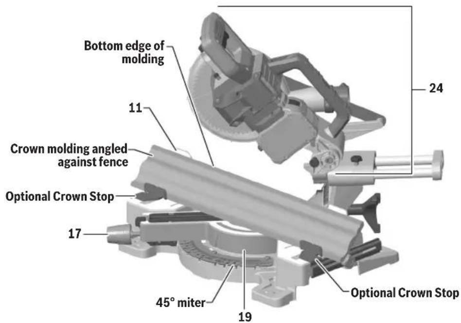
text_image
Bottom edge of molding 11 24 Crown molding angled against fence Optional Crown Stop 17 45° miter 19 Optional Crown StopSaw Operations
Crown Molding Lying Flat on Table

Use clamping position that does not interfere with operation. Before switching "ON", lower head assembly to make sure clamp clears guard and head assembly.

Be aware of the path of the saw blade. Make a dry run with the battery pack disconnected and the saw switched OFF by conducting a simulated cutting cycle, and observe the projected path of the saw blade. Keep hands at least six (6) inches (152mm) away from the projected path of the saw blade.
NOTE: Position workpiece with its back flat on the saw table (Fig. 48, 19).
Fig. 48
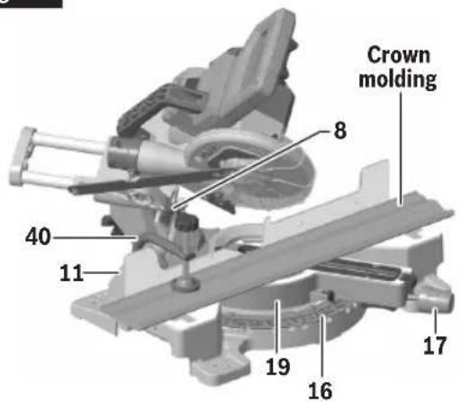
text_image
Crown molding 8 40 11 19 16 17Bevel Scale Settings

text_image
30 40 33.9 30 33.9For 45° spring angle
Miter Scale Settings
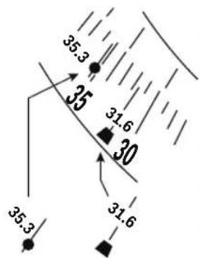
text_image
35.3 35 31.6 30 35.3 31.6For 45^ spring angle
For 38^ spring angle
Always place top edge of molding against fence (11). (The decorative edge is at the bottom of crown molding.)
"Spring angle" refers to angle between wall and crown molding.
Cutting crown molding flat on the table (19) can be done either as a chop cut or a slide cut depending on the width of the workpiece.
- For 90° corner, set the bevel and miter angles, see the table "Miter and Bevel Settings for Standard Crown Molding Cuts (With Molding Flat on Table)" on page 45. Tighten the miter lock knob (17) and the bevel lock knob (Fig. 44, 30).
- Position molding on saw table (Fig. 48, 19). Clamp workpiece in place using the quick clamp (40).
- Follow either the procedure "Chop Cuts" on page 35 or "Slide Cuts" on page 36.
- Wait until saw blade comes to a complete stop before returning head assembly (Fig. 47, 24) to the raised position and then remove workpiece.
NOTE: Always take a cut using scrap to confirm correct angles.
See the table "Miter and Bevel Setings for Standard Crown Molding Cuts (With Molding Flat on Table)" on page 45 for helpful hints on cutting crown molding for corners that have 90^ angles.
Saw Operations
Miter and Bevel Settings for Standard Crown Molding Cuts (With Molding Flat on Table)
Assumptions: Molding is milled consistently. Corner is exactly 90°.
| MoldingSpring Angle 38° | MoldingSpring Angle 45° | |||
| NOTE: Always place top edge against fence | Miter (Table)Setting | Bevel (Tilt)Setting | Miter (Table)Setting | Bevel (Tilt)Setting |
| Inside Corner | ||||
| Left end (Fig. 49, A)Use the left end of the cut | 31.6° Right 33.9° Left 35.3° Right 30° Left | |||
| Right end (Fig. 49, B)Use the right end of the cut | 31.6° Left 33.9° Right 35.3° Left 30° Right | |||
| Outside Corner | ||||
| Left end (Fig. 49, C)Use the left end of the cut | 31.6° Left 33.9° Right 35.3° Left 30° Right | |||
| Right end (Fig. 49, D)Use the right end of the cut | 31.6° Right 33.9° Left 35.3° Right 30° Left | |||
Fig. 49
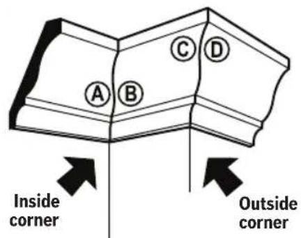
text_image
A B C D Inside corner Outside corner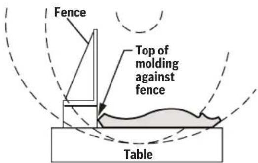
text_image
Fence Top of molding against fence Table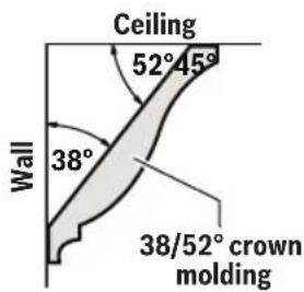
text_image
Ceiling 52°45° Wall 38° 38/52° crown molding38^ spring angle
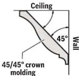
text_image
Ceiling 45° Wall 45/45° crown molding45^ spring angle
Saw Operations
Special Cuts
WARNING
Use clamping position that does not interfere with operation. Before switching on, lower head assembly to make sure clamp clears guard and head assembly.
WARNING
Be aware of the path of the saw blade. Make a dry run with the battery pack disconnected and the saw switched OFF by conducting a simulated cutting cycle, and observe the projected path of the saw blade. Keep hands at least six (6) inches (152mm) away from the projected path of the saw blade.
Cutting bowed material and round material are only two examples of special cuts.
Cutting Bowed Material
If workpiece is bowed or warped, clamp it with the outside bowed face toward the fence (Fig. 50, 11). Always make certain that there is no gap between the workpiece, fence and table (19) along the line of cut. Bent or warped workpieces can twist or rock and may cause binding on the spinning saw blade while cutting.
Fig. 50
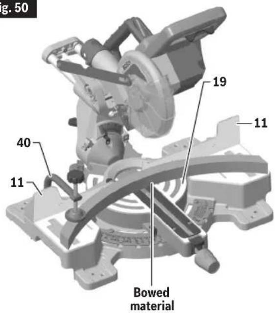
text_image
g. 50 19 11 40 11 Bowed materialCutting Round or Irregularly Shaped Material
For round material such as dowel rods or tubing, always use a clamp (Fig. 51, 40) or a fixture designed to clamp the workpiece firmly against the fence (11) and table (19). Rods have a tendency to roll while being cut, causing the blade to "bite" and pull the work with your hand into the blade.
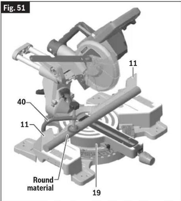
text_image
Fig. 51 11 40 11 Round material 19Maintenance and Lubrication
WARNING
To avoid accidents, always disconnect battery pack from tool before cleaning or performing any maintenance.
Service
WARNING
All tool service should be performed by a Bosch Factory Service
Center or an Authorized Bosch Service Station. Preventive maintenance performed by unauthorized personnel may result in misplacing of internal wires and components which could cause serious hazard.
Batteries
Be alert for battery packs that are nearing their end of life. If you notice decreased tool performance or significantly shorter running time between charges then it is time to replace the battery pack. Failure to do so can cause the tool to operate improperly or damage the charger.
Care of Blades
Blades become dull even from cutting regular lumber. If you find yourself forcing the saw forward to cut instead of just guiding it through the cut, chances are the blade is dull or coated with wood pitch.
When cleaning gum and wood pitch from blade, unplug the saw and remove the blade. Remember, blades are designed to cut, so handle carefully. Wipe the blade with kerosene or similar solvent to remove the gum and pitch. Unless you are experienced in sharpening blades, we recommend you do not try.
Tool Lubrication
Preventive maintenance performed by unauthorized personnel may result in misplacing of internal wires and components which could cause serious hazard. We recommend that all tool service be performed by a Bosch factory Service Center or Authorized Bosch Service Station.
Periodically lubricate moving parts with a silicone, or light oil spray. Do not use grease because it tends to attract and hold sawdust.
Bearings
All bearings in this tool are lubricated with a sufficient amount of high-grade lubricant for the life of the unit under normal operating conditions. No further lubrication is required.
Cleaning
WARNING
Certain cleaning agents and solvents damage plastic parts. Some
of these are: gasoline, carbon tetrachloride, chlorinated cleaning solvents, ammonia and household detergents that contain ammonia.
Ventilation openings and switch levers must be kept clean and free of foreign matter. Use a brush to remove dust and debris from the vent openings and the guard mechanisms. Do not attempt to clean by inserting pointed objects through openings.
Regularly check to make sure the lower guard and all moving parts are working properly. Regularly check that the lower guard can move from the fully open to fully closed position without interference. Ensure that the lower guard moves to the fully closed position when the Main Handle is moved to the raised position.
Troubleshooting
Troubleshooting Guide - Electrical
| PROBLEM CAUSE CORRECTIVE ACTION | ||
| Brake does not stop blade in about 5 seconds. | 1. Blade bolt loose.2. Other. | 1. Tighten blade bolt.2. Authorized service. |
| Motor does not start. 1. Battery pack not charged.2. Battery pack not installed properly.3. Battery pack temperature is too hot or cold for operation.4. Electronic Motor Protection turned tool off.5. Burned out switch.6. Other. | 1. Charge battery if needed.2. Confirm battery is locked and secured to the tool.3. Let battery sit a few minutes or until it reaches normal operating temperature.4. Remove battery an replace.5. Let tool sit a few minutes or until it reaches normal operating temperature.6. Have switch replaced by an Authorized Bosch Service Center or Service Station.7. Authorized service. | |
| LED light flashing, motor does not start. | 1. Tool is over heated.2. Battery is over heated. | 1. Let tool cool down.2. Exchange the battery. |
Troubleshooting
Troubleshooting Guide - General
| PROBLEM CAUSE CORRECTIVE ACTION | ||
| Blade hits table. Misalignment. Authorized service. | ||
| Angle of cut not accurate. Angle stops at 0° or 45° need adjustment. | See “Adjustments” on page 22. | |
| Cannot rotate table to change miter angle. | 1. Miter lock knob is tightened.2. Miter detent lever is engaged with a detent (slot) in detent plate.3. Sawdust accumulation. | 1. Turn miter lock knob counter-clockwise to loosen.2. Disengage detent system from detent slot. See “Using Miter Detent System” on page 34.3. Vacuum or blow out dust around turntable. Wear eye protection. |
| Head assembly will not fully raise or blade guard will not fully close. | 1. Head assembly lock pin is engaged.2. Sawdust accumulation.3. Sawdust accumulation. | 1. Pull out the head assembly lock pin, allowing head assembly to go up. See “To Disengage the Head Assembly Lock Pin” on page 22.2. Clean head assembly.3. Authorized service. |
| Blade binds, jams, burns wood.Rough cuts. | 4. Improper operation.1. Dull blade.2. Improper blade.3. Bent blade. | 1. See “Saw Operations” starting on page 34.2. Replace or sharpen blade.3. Replace with 7-1/4” (184mm) diameter blade designed for material being cut.4. Replace blade. |
| Head assembly slides forward and back when making a chop cut. | Slide rail lock knob has been loosened. | Tighten the slide rail lock knob (Fig. 38 on page 35, 33) by turning it clockwise. |
Troubleshooting
| PROBLEM CAUSE CORRECTIVE ACTION | ||
| Tool vibrates or shakes. 1. Saw blade | not round.2. Saw blade damaged.3. Saw blade loose.4. Other. | 1. Replace blade.2. Replace blade.3. Check that blade is properly seated on the inner washer.See “Removing and Installing Blades” on page 19.4. Authorized service. |
| Head assembly does not slide freely when attempting a slide cut. | The slide rail lock knob has been tightened. | Loosen the slide rail lock knob (Fig. 38 on page 35, 33) by turning it counterclockwise. |
| Blade does not cut completely through workpiece. | Replacement blade is less than 7-1/4" (184mm) diameter. | Change to a blade that is fully 7-1/4" (184mm) diameter. |
Attachments and Accessories
GAM 220 MF and GAM 270 MFL Digital Angle Finder/Compound Cut Calculator/Protractor/ Level – Gives you the information needed to position cuts so that they fit together precisely even if the room is out of square.
MS1233 Crown Stop Set – Correctly hold crown molding in an inclined position against fence. Set molding for simple vertical cutting – no compound cutting required.
GTA3800 Portable Miter Saw Stand with Wheels
T4B Gravity-Rise Wheeled Miter Saw Stand
natural_image
Prohibition sign showing a hand crossed out by a diagonal line, enclosed in a circle (no text or symbols)
text_image
Do not carry the saw by this handle. Ne portez pas la scie par cette poignée. No transporte la sierra por este mango.ZONES DE RISQUE DE CHOC EN RETOUR ZONE DÉSIGNÉE D'INTERDICTION DE PRÉHENSION POUR LE TRANSPORT
text_image
Technical diagram of a mechanical assembly with numbered parts for identificationtext_image
Technical diagram of a mechanical assembly with numbered parts for identificationnatural_image
Simple line drawing of a faucet with a handle and base (no text or symbols)text_image
Germosky Boltzmann Sachan University of Technology Hindi University of Technology BOSCH BOSCHnatural_image
Simple line drawing of a folded paper or sheet (no text or symbols)natural_image
3D mechanical assembly diagram showing a frame-like component with labeled part '39' (no readable text or symbols beyond label)natural_image
Mechanical assembly diagram showing a cutting machine with labeled component '40' (no text or symbols beyond label)Ouvrage
natural_image
Prohibition sign showing a hand crossed out by a diagonal line, enclosed in a circle (no text or symbols)
text_image
Do not carry the saw by this handle. Ne portez pas la scie par cette poignée. No transporte la sierra por este mango.ZONAS DE PELIGRO DESIGNADAS ÁREA DESIGNADA COMO NO APTA PARA EL TRANSPORTE
text_image
Technical diagram of a mechanical assembly with numbered parts for identificationnatural_image
Simple line drawing of a vertical pipe with a stopper and a handle (no text or symbols)text_image
SOMEN BOSCH Operating Safety measures Automotive disassembly Mechanical displacement control system COM-BUSCH BOSCHBolsa colectora de polvo (32)
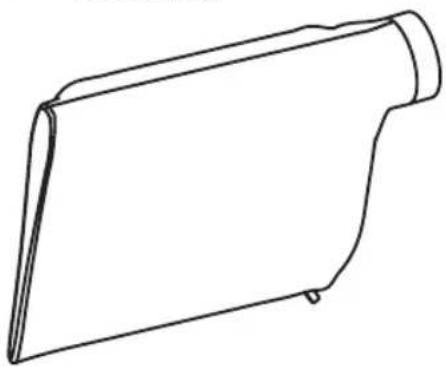
natural_image
Simple line drawing of a folded paper or sheet (no text or symbols)natural_image
3D mechanical assembly diagram showing a component with labeled parts (no readable text or symbols)ARM (BSD 3-clause) - CMSIS-core 4 and earlier
Copyright © 2009-2020 ARM LIMITED
All rights reserved.
Redistribution and use in source and binary forms, with or without modification, are permitted provided that the following conditions are met.
• Redistributions of source code must retain the above copyright notice, this list of conditions and the following disclaimer.
- Redistributions in binary form must reproduce the above copyright notice, this list of conditions and the following disclaimer in the documentation and/or other materials provided with the distribution.
- Neither the name of ARM nor the names of its contributors may be used to endorse or promote products derived from this software without specific prior written permission.
THIS SOFTWARE IS PROVIDED BY THE COPYRIGHT HOLDERS AND CONTRIBUTORS "AS IS" AND ANY EXPRESS OR IMPLIED WARRANTIES, INCLUDING, BUT NOT LIMITED TO, THE IMPLIED WARRANTIES OF MERCHANTABILITY AND FITNESS FOR A PARTICULAR PURPOSE ARE DISCLAIMED. IN NO EVENT SHALL THE COPYRIGHT OWNER OR CONTRIBUTORS BE LIABLE FOR ANY DIRECT, INDIRECT, INCIDENTAL, SPECIAL, EXEMPLARY, OR CONSEQUENTIAL DAMAGES (INCLUDING, BUT NOT LIMITED TO, PROCUREMENT OF SUBSTITUTE GOODS OR SERVICES; LOSS OF USE, DATA, OR PROFITS; OR BUSINESS INTERRUPTION) HOWEVER CAUSED AND ON ANY THEORY OF LIABILITY, WHETHER IN CONTRACT, STRICT LIABILITY, OR TORT (INCLUDING NEGLIGENCE OR OTHERWISE) ARISING IN ANY WAY OUT OF THE USE OF THIS SOFTWARE, EVEN IF ADVISED OF THE POSSIBILITY OF SUCH DAMAGE.
Copyright © 2011 Petteri Aimonen
This software is provided 'as-is', without any express or implied warranty. In no event will the authors be held liable for any damages arising from the use of this software.
Permission is granted to anyone to use this software for any purpose, including commercial applications, and to alter it and redistribute it freely, subject to the following restrictions:
- The origin of this software must not be misrepresented; you must not claim that you wrote the original software. If you use this software in a product, an acknowledgment in the product documentation would be appreciated but is not required.
- Altered source versions must be plainly marked as such, and must not be misrepresented as being the original software.
- This notice may not be removed or altered from any source distribution.
Amonen (zlib) - Nanopb
Copyright © 2011 Petteri Aimonen
Limited Warranty of Bosch Portable and Benchtop Power Tools ("Limited Warranty")
Robert Bosch Tool Corporation ("Bosch", "we" or "our") warrants to the original end-user purchaser only that each BOSCH ^6 -branded portable and benchtop power tool and battery (each, a "Product") will be free from defects in material or workmanship for the period of time listed in the chart below for the "Product Category" applicable for such Product (as applicable, the "Warranty Period"):
| Product Category Warranty Period | ____ |
| 18V Cordless Power Tools, 18V Benchtop Power Tools and 18V Chargers Five (5) years from the date of purchase | date of purchase |
| 18V Power Tool Batteries Three (3) years from the date of purchase | |
| 12V Cordless Power Tools and 12V Chargers One (1) year from the date of purchase | |
| 12V Power Tool Batteries One (1) year from the date of purchase | |
| Corded Portable Power Tools and Corded Benchtop Power Tools One (1) year from the date of purchase |
OUR SOLE OBLIGATION AND YOUR EXCLUSIVE REMEDY under this Limited Warranty and, to the extent permitted by law, under any warranty or condition implied by law, shall be the repair or replacement of parts, without charge, which are defective in material or workmanship and which have not been abused, misused, carelessly handled, or repaired by persons other than Bosch or a Bosch Authorized Service Center.
Normal wear and tear of your Product is not covered by this Limited Warranty. As a result, Product parts that may become worn or exhausted over time due to normal wear and tear (including, without limitation, air filters, blade clamps, brushes, bumpers, bumper cover washers, chucks, cords, driver belts, driver blades, isolators, lifters, o-rings, pistons, piston/driver assemblies, piston stops, saw shoes, seals, strikers, etc.), or any other service or repairs required due to normal wear and tear on a Product, are not covered by this Limited Warranty.
To make a claim under this Limited Warranty, you must return the complete Product, transportation prepaid, to any Bosch Factory Service Center or Bosch Authorized Service Center. Please include a dated proof of purchase with your Product so we can determine if your Product is within the Warranty Period. If you do not have the dated proof of purchase for the Product that is the subject of your claim, we will use the Product's production code to determine whether the Product is within the Warranty Period. For locations of nearby Bosch Factory Service Centers or Bosch Authorized Service Centers, please use our service locator at https://www.boschtools.com/us/en/service/service-center-locator/. For more information on Limited Warranty performance, please contact our customer service at 1-877-267-2499.
THIS LIMITED WARRANTY DOES NOT APPLY TO BOSCH®-BRANDED:
(i) MEASURING TOOLS,
(ii) ACCESSORY ITEMS SUCH AS CIRCULAR SAW BLADES, DRILL BITS, ROUTER BITS, JIGSAW BLADES, SANDING BELTS, GRINDING WHEELS AND OTHER SIMILAR TYPES OF ITEMS; OR
(iii) CARRYING CASES OR CARRYING BAGS.
ANY IMPLIED WARRANTIES FOR A PRODUCT SHALL BE LIMITED IN DURATION TO THE SHORTER OF (i) THE APPLICABLE WARRANTY PERIOD FOR SUCH PRODUCT/PRODUCT CATEGORY LISTED ABOVE, OR (ii) SUCH DURATION AS WOULD OTHERWISE APPLY UNDER APPLICABLE LAW IF THIS LIMITED WARRANTY WERE NOT OFFERED BY BOSCH. SOME STATES IN THE U.S., AND SOME CANADIAN PROVINCES, DO NOT ALLOW LIMITATIONS ON HOW LONG AN IMPLIED WARRANTY LASTS, SO THE ABOVE LIMITATION MAY NOT APPLY TO YOU.
IN NO EVENT SHALL BOSCH BE LIABLE FOR ANY INCIDENTAL OR CONSEQUENTIAL DAMAGES (INCLUDING BUT NOT LIMITED TO LIABILITY FOR LOSS OF PROFITS) ARISING FROM THE SALE OR USE OF THIS PRODUCT. SOME STATES IN THE U.S. AND SOME CANADIAN PROVINCES (INCLUDING, WITHOUT LIMITAITON, QUEBEC) DO NOT ALLOW THE EXCLUSION OR LIMITATION OF INCIDENTAL OR CONSEQUENTIAL DAMAGES, SO THE ABOVE LIMITATION OR EXCLUSION MAY NOT APPLY TO YOU.
THIS LIMITED WARRANTY GIVES YOU SPECIFIC LEGAL RIGHTS, AND YOU MAY ALSO HAVE OTHER RIGHTS WHICH VARY FROM STATE TO STATE IN THE U.S., PROVINCE TO PROVINCE IN CANADA AND FROM COUNTRY TO COUNTRY.
THIS LIMITED WARRANTY APPLIES ONLY TO PRODUCTS SOLD WITHIN THE UNITED STATES OF AMERICA AND CANADA. FOR WARRANTY COVERAGE WITHIN OTHER COUNTRIES, CONTACT YOUR LOCAL BOSCH® BRAND TOOL DEALER OR IMPORTER.
V202211
© Robert Bosch Tool Corporation
1800 W. Central Road
Mt. Prospect, IL 60056-2230
2610070464 /2022