CM8S Professional - Saw BOSCH - Free user manual and instructions
Find the device manual for free CM8S Professional BOSCH in PDF.

User questions about CM8S Professional BOSCH
0 question about this device. Answer the ones you know or ask your own.
Ask a new question about this device
Download the instructions for your Saw in PDF format for free! Find your manual CM8S Professional - BOSCH and take your electronic device back in hand. On this page are published all the documents necessary for the use of your device. CM8S Professional by BOSCH.
USER MANUAL CM8S Professional BOSCH
IMPORTANT Read Before Using
IMPORTANT Lire avant usage
IMPORTANTE Leer antes de usar

Operating/Safety Instructions Consignes d'utilisation/de sécurité Instrucciones de funcionamiento y seguridad
CM8S
natural_image
Technical line drawing of a Bosch anti-mach tool assembly (no text or symbols on the diagram itself)
BOSCH
Call Toll Free for Consumer Information and Service Locations Pour obtenir des informations et les adresses de nos centres de service après-vente, appelez ce numéro gratuit Llame gratis para obtener información para el consumidor y ubicaciones de servicio
1-877-BOSCH99 (1-877-267-2499) www.boschtools.com
For English Version See page 2
| Safety SymbolsThe definitions below describe the level of severity for each signal word.Please read the manual and pay attention to these symbols. | |
| This is the safety alert symbol. It is used to alert you to potential personal injury hazards. Obey all safety messages that follow this symbol to avoid possible injury or death. | |
| DANGER indicates a hazardous situation which, if not avoided, will result in death or serious injury. | |
| WARNING indicates a hazardous situation which, if not avoided, could result in death or serious injury. | |
| CAUTION indicates a hazardous situation which, if not avoided, could result in minor or moderate injury. | |
Table of Contents
Safety Symbols....2
General power tool safety warnings .....4
Safety instructions for miter saws .....5
▶Double-Insulated Tools .....6
Additional Safety Rules ....6
▶Extension Cords .....7
Electrical Requirements....8
Symbols 9
Getting To Know Your Miter Saw .....11
Cutting Capacities .....13
Assembly 14
▶Unpacking and Checking Contents .....14
▶Attaching Loose Parts .....16
▼Storing the 5mm Hex Key .....16
▼Attaching 60° Auxiliary clamp hole .....16
▶Removing and Installing Blades .....17
▼Removing Blade .....17
▼Installing 8-1/2" Blade .....17
▶Assembling Dust Collection System .....18
▼Attaching the Dust Bag .....18
▼Using and Cleaning the Dust Bag .....18
▼Attaching a Vacuum Cleaner/dust extractor . . .18
▼Repositioning or Removing the Rubber Deflector ....18
▶Using the Head Assembly Lock Pin .....19
▼Head Assembly Lock Pin .....19
▼To Engage the Head Assembly Lock Pin: ...19
▼To Disengage the Head Assembly Lock Pin: .19
Adjustments .....20
▶Depth of Cut .....20
▼Setting Blade Depth for Normal Full-Depth Cuts .....20
▼Setting Blade Depth for Non-Through Cuts for Cutting Grooves .....20
▶Miter Detent System .....21
▼Calibrating Miter Detent System .....21
▼Miter Scale Pointer Adjustment .....21
▶0° Bevel Stop .....22
▼Checking 0° Bevel Stop Setting .....22
▶Kerf Insert Adjustment .....22
▶0° Bevel Stop .....23
▼Calibrating Blade at 0° Bevel (90° to the table) .....23
▼Adjusting Bevel Scale Pointer .....23
▶45° Bevel Stop .....24
▼Checking left 45° Bevel Adjustment .....24
▼Calibrating Blade at left 45° Bevel .....24
Transporting 25
▼Preparing To Lift The Saw .....25
▼Lift the saw by the top cary handle .....25
▼Lift the saw by the cast in carry handles . . .25
Placement and Mounting .....26
▼Workbench Permanent Attachment .....26
▼Alternate Mounting .....26
▼Temporary Mounting Using Clamps .....26
▼Mounting to Bosch Jobsite Stands .....26
Preparing for Saw Operations .....27
▶Switch Activation .....27
▶Body and Hand Position .....27
▶Workpiece Support .....29
▼Clamps .....29
▼Sliding Fences 30
▼Operating Sliding Fences .....30
▼Removing Sliding Fences .....30
▶Workpiece Support .....31
▼Long Workpiece Support .....31
▼Additional Workpiece Support .....31
Saw Operations ....32
▶Miter Detent System .....32
▼Using Miter Detent system .....32
Table of Contents
▼Miter Detent Override ....32
▼Adjusting front stabilizing foot .....32
▶Chop Cut ....33
▼What's a Chop Cut? ....33
▼Making a Chop Cut .....33
▶Slide Cut .....34
▼What's a Slide Cut?....34
▼Making a Slide Cut .....34
▶Miter Cuts .....35
▼What's a Miter Cut ....35
▼Reading the Miter Scale .....35
▼Making a Miter Cut .....35
▶Bevel Cuts .....36
▼Setting the Saw to Make a Bevel Cut .....36
▶Compound Cuts .....37
▶Cutting Grooves .....38
▶Cutting Base Molding .....39
▶Cutting Crown Molding .....39
▶ Crown Molding Angled to Table and Fence . . .40
▼Miter and Bevel Settings for Standard Crown Molding Cuts .....40
▶ Crown Molding Lying Flat on Table .....41
▼Miter and Bevel Settings for Standard Crown Molding Cuts .....41
▶Auxiliary fence .....42
▼Making an Auxiliary Fence: .....42
▶ Crown Molding Auxiliary Fence .....43
▼Making Crown Molding Auxiliary Fence: . . . .43
▼First-Time Use of the Auxiliary Fence: .....43
▼Cutting Bowed Material .....45
▼Cutting Round or Irregularly Shaped Material 45
Maintenance and Lubrication .....46
▶Service 46
▶Motor Brushes .....46
▼Motor Brush Replacement .....46
▶Cleaning....47
▶Care of Blades .....47
▶Tool Lubrication .....47
▶Bearings .....47
▶Troubleshooting Guide - Electrical .....47
Troubleshooting .....47
Accessories and Attachments .....49
Française ....50
Español 98
General power tool safety warnings
WARNING
Read all safety warnings, instructions, illustrations and specifications provided with this power tool. Failure to follow all instructions listed below may result in electric shock, fire
and/or serious injury.jury.
Save all warnings and instructions for future reference.
The term “power tool” in the warnings refers to your mains-operated (corded) power tool or BATTERY-operated (cordless) power tool.
▶ Work area safety
Keep work area clean and well lit. Cluttered or dark areas invite accidents.
Do not operate power tools in explosive atmospheres, such as in the presence of flammable liquids, gases or dust. Power tools create sparks which may ignite the dust or fumes.
Keep children and bystanders away while operating a power tool. Distractions can cause you to lose control.
Electrical Safety
Power tool plugs must match the outlet. Never modify the plug in any way. Do not use any adapter plugs with earthed (grounded) power tools. Unmodified plugs and matching outlets will reduce risk of electric shock.
Avoid body contact with earthed or grounded surfaces, such as pipes, radiators, ranges and refrigerators. There is an increased risk of electric shock if your body is earthed or grounded.
Do not expose power tools to rain or wet conditions. Water entering a power tool will increase the risk of electric shock.
Do not abuse the cord. Never use the cord for carrying, pulling or unplugging the power tool. Keep cord away from heat, oil, sharp edges or moving parts. Damaged or entangled cords increase the risk of electric shock.
When operating a power tool outdoors, use an extension cord suitable for outdoor use. Use of a cord suitable for outdoor use reduces the risk of electric shock.
If operating a power tool in a damp location is unavoidable, use a ground fault circuit interrupter (GFCI) protected supply. Use of an GFCI reduces the risk of electric shock.
▶ Personal Safety
Stay alert, watch what you are doing and use common sense when operating a power tool. Do not use a power tool while you are tired or under the influence of drugs, alcohol or medication. A moment of inattention while operating power tools may result in serious personal injury.
Use personal protective equipment. Always wear
eye protection. Protective equipment such as dust mask, non-skid safety shoes, hard hat, or hearing protection used for appropriate conditions will reduce personal injuries.
Prevent unintentional starting. Ensure the switch is in the off-position before connecting to power source and/or BATTERY pack, picking up or carrying the tool. Carrying power tools with your finger on the switch or energizing power tools that have the switch on invites accidents.
Remove any adjusting key or wrench before turning the power tool on. A wrench or a key left attached to a rotating part of the power tool may result in personal injury.
Do not overreach. Keep proper footing and balance at all times. This enables better control of the power tool in unexpected situations.
Dress properly. Do not wear loose clothing or jewelry. Keep your hair, clothing and gloves away from moving parts. Loose clothes, jewelry or long hair can be caught in moving parts.
If devices are provided for the connection of dust extraction and collection facilities, ensure these are connected and properly used. Use of dust collection can reduce dust-related hazards.
Do not let familiarity gained from frequent use of tools allow you to become complacent and ignore tool safety principles. A careless action can cause severe injury within a fraction of a second.
▶ Power tool use and care
Do not force the power tool. Use the correct power tool for your application. The correct power tool will do the job better and safer at the rate for which it was designed.
Do not use the power tool if the switch does not turn it on and off. Any power tool that cannot be controlled with the switch is dangerous and must be repaired.
Disconnect the plug from the power source and/or remove the BATTERY pack, if detachable, from the power tool before making any adjustments, changing accessories, or storing power tools. Such preventive safety measures reduce the risk of starting the power tool accidentally.
General power tool safety warnings
Store idle power tools out of the reach of children and do not allow persons unfamiliar with the power tool or these instructions to operate the power tool. Power tools are dangerous in the hands of untrained users.
Maintain power tools and accessories. Check for misalignment or binding of moving parts, breakage of parts and any other condition that may affect the power tool's operation. If damaged, have the power tool repaired before use. Many accidents are caused by poorly maintained power tools.
Keep cutting tools sharp and clean. Properly maintained cutting tools with sharp cutting edges are less likely to bind and are easier to control. Use the power tool, accessories and tool bits etc.
in accordance with these instructions, taking into account the working conditions and the work to be performed. Use of the power tool for operations different from those intended could result in a hazardous situation.
Keep handles and grasping surfaces dry, clean and free from oil and grease. Slippery handles and grasping surfaces do not allow for safe handling and control of the tool in unexpected situations.
▶ Service
Have your power tool serviced by a qualified repair person using only identical replacement parts. This will ensure that the safety of the power tool is maintained.
Safety instructions for miter saws
Miter saws are intended to cut wood or wood-like products, they cannot be used with abrasive cut-off wheels for cutting ferrous material such as bars, rods, studs, etc. Abrasive dust causes moving parts such as the lower guard to jam. Sparks from abrasive cutting will burn the lower guard, the kerf insert and other plastic parts.
Use clamps to support the workpiece whenever possible. If supporting the workpiece by hand, you must always keep your hand at least 100 mm (4 in.) from either side of the saw blade. Do not use this saw to cut pieces that are too small to be securely clamped or held by hand. If your hand is placed too close to the saw blade, there is an increased risk of injury from blade contact.
The workpiece must be stationary and clamped or held against both the fence and the table. Do not feed the workpiece into the blade or cut "freehand" in any way. Unrestrained or moving workpieces could be thrown at high speeds, causing injury.
Push the saw through the workpiece. Do not pull the saw through the workpiece. To make a cut, raise the saw head and pull it out over the workpiece without cutting, start the motor, press the saw head down and push the saw through the workpiece. Cutting on the pull stroke is likely to cause the saw blade to climb on top of the workpiece and violently throw the blade assembly towards the operator.
Never cross your hand over the intended line of cutting either in front or behind the saw blade. Supporting the workpiece “cross handed” i.e. holding the workpiece to the right of the saw blade
with your left hand or vice versa is very dangerous. Do not reach behind the fence with either hand closer than 100 mm (4 in.) from either side of the saw blade, to remove wood scraps, or for any other reason while the blade is spinning. The proximity of the spinning saw blade to your hand may not be obvious and you may be seriously injured.
Inspect your workpiece before cutting. If the workpiece is bowed or warped, clamp it with the outside bowed face toward the fence. Always make certain that there is no gap between the workpiece, fence and table along the line of the cut. Bent or warped workpieces can twist or shift and may cause binding on the spinning saw blade while cutting. There should be no nails or foreign objects in the workpiece.
Do not use the saw until the table is clear of all tools, wood scraps, etc., except for the workpiece. Small debris or loose pieces of wood or other objects that contact the revolving blade can be thrown with high speed.
Cut only one workpiece at a time. Stacked multiple workpieces cannot be adequately clamped or braced and may bind on the blade or shift during cutting.
Ensure the miter saw is mounted or placed on a level, firm work surface before use. A level and firm work surface reduces the risk of the miter saw becoming unstable.
Plan your work. Every time you change the bevel or miter angle setting, make sure the adjustable fence is set correctly to support the workpiece and will not interfere with the blade or the
Safety instructions for miter saws
guarding system. Without turning the tool "ON" and with no workpiece on the table, move the saw blade through a complete simulated cut to assure there will be no interference or danger of cutting the fence.
Provide adequate support such as table extensions, saw horses, etc. for a workpiece that is wider or longer than the table top. Workpieces longer or wider than the miter saw table can tip if not securely supported. If the cut-off piece or workpiece tips, it can lift the lower guard or be thrown by the spinning blade.
Do not use another person as a substitute for a table extension or as additional support. Unstable support for the workpiece can cause the blade to bind or the workpiece to shift during the cutting operation pulling you and the helper into the spinning blade.
The cut-off piece must not be jammed or pressed by any means against the spinning saw blade. If confined, i.e. using length stops, the cut-off piece could get wedged against the blade and thrown violently.
Always use a clamp or a fixture designed to properly support round material such as rods or tubing. Rods have a tendency to roll while being cut, causing the blade to "bite" and pull the work
with your hand into the blade.
Let the blade reach full speed before contacting the workpiece. This will reduce the risk of the workpiece being thrown.
If the workpiece or blade becomes jammed, turn the miter saw off. Wait for all moving parts to stop and disconnect the plug from the power source and/or remove the battery pack. Then work to free the jammed material. Continued sawing with a jammed workpiece could cause loss of control or damage to the miter saw.
After finishing the cut, release the switch, hold the saw head down and wait for the blade to stop before removing the cut-off piece. Reaching with your hand near the coasting blade is dangerous.
Hold the handle firmly when making an incomplete cut or when releasing the switch before the saw head is completely in the down position. The braking action of the saw may cause the saw head to be suddenly pulled downward, causing a risk of injury.
Avoid overheating saw blade tips.
Additional Safety Rules
▶ Double-Insulated Tools
Double insulation ☐ is a design concept used in electric power tools which eliminates the need for the three-wire grounded power cord and grounded power supply system. It is a recognized and approved system by Underwriter's Laboratories, CSA and Federal OSHA authorities.
- Servicing of a tool with double insulation requires care and knowledge of the system and should be performed only by a qualified service technician.
WHEN SERVICING, USE ONLY IDENTICAL REPLACEMENT PARTS.
- POLARIZED PLUGS. Your tool is equipped with a polarized plug (one blade is wider than the other); this plug will fit in a polarized outlet only one way. If the plug does not fit fully in the outlet, reverse the plug. If it still does not fit, contact a qualified electrician to install the proper outlet. To reduce the risk of electrical shock, do not change the plug in any way.
Additional Safety Rules
▶ Extension Cords
- Replace damaged cords immediately. Use of damaged cords can shock, burn or electrocute.
- If an extension cord is necessary, a cord with adequate size conductors should be used to prevent excessive voltage drop, loss of power or overheating. The table shows the correct size to use, depending on cord length and nameplate amperage rating of tool. If in doubt, use the next heavier gauge. Always use UL and CSA listed extension cords.
RECOMMENDED SIZES OF EXTENSION CORDS 120 VOLT ALTERNATING CURRENT TOOLS
| Tool's Ampere Rating | Cord Size in A.W.G. | Wire Sizes in mm ^2 | ||||||
| Cord Length in Feet | Cord Length in Meters | |||||||
| 25 | 50 | 100 | 150 | 15 | 30 | 60 | 120 | |
| 3-6 | 18 | 16 | 16 | 14 | 0.75 | 0.75 | 1.5 | 2.5 |
| 6-8 | 18 | 16 | 14 | 12 | 0.75 | 1.0 | 2.5 | 4.0 |
| 8-10 | 18 | 16 | 14 | 12 | 0.75 | 1.0 | 2.5 | 4.0 |
| 10-12 | 16 | 16 | 14 | 12 | 1.0 | 2.5 | 4.0 | - |
| 12-16 | 14 | 12 | - | - | - | - | - | - |
NOTE: The smaller the gauge number, the higher the cord capacity.
- THINK SAFETY! SAFETY IS A COMBINATION OF OPERATOR'S COMMON SENSE, KNOWLEDGE
OF THE SAFETY AND OPERATING
INSTRUCTIONS AND ALERTNESS AT ALL TIMES WHEN THE MITER SAW IS BEING USED.
WARNING THE WARNINGS SHOWN BELOW CAN BE FOUND ON YOUR TOOL. THESE WARNINGS ARE ONLY A CONDENSED FORM OF THE MORE DETAILED SAFETY RULES AND PRECAUTIONS THAT APPEAR IN YOUR OWNER'S MANUAL. THEY SERVE AS A REMINDER OF ALL SAFETY RULES NEEDED FOR SAFE OPERATION OF THIS MITER SAW.
⚠ WARNING Some dust created by power sanding, sawing, grinding, drilling and other construction activities contains chemicals known to cause cancer, birth defects or other reproductive harm. Some examples of these chemicals are:
- Lead from lead-based paints,
• Crystalline silica from bricks and cement and other masonry products, and - Arsenic and chromium from chemically treated lumber.
Your risk from these exposures varies, depending on how often you do this type of work. To reduce your exposure to these chemicals: work in a well-ventilated area, and work with approved safety equipment, such as those dust masks that are specially designed to filter out microscopic particles.
WARNING
Do not use the Bosch CM8S miter saw to cut fiber cement board. Cutting materials containing crystalline silica may create exposures to respirable silica dust.
WARNING
Before each use, review all warnings located on the miter saw.

DESIGNATED DANGER ZONES
Avoid positioning hands, fingers or arms
Electrical Requirements
- Connect this saw to a 120V, 15-amp branch circuit with a 15-amp fuse or circuit breaker. Using the wrong size fuse can damage the motor.
- Fuses may “blow” or circuit breakers may trip frequently if motor is overloaded. Overloading can occur if you feed the blade into the workpiece too rapidly or start and stop too often in a short time.
- Most motor troubles may be traced to loose or incorrect connections, overload or low voltage (such as small size wire in the supply circuit or overly long supply circuit wire). Always check the connections, the load and the supply circuit whenever motor does not work well.
Symbols
Important: Some of the following symbols may be used on your tool. Please study them and learn their meaning. Proper interpretation of these symbols will allow you to operate the tool better and safer.
| Symbol Designation / Explanation | |
| V Volts (voltage) | |
| A Amperes (current) | |
| Hz Hertz (frequency, cycles per second) | |
| W Watt (power) | |
| kg Kilograms (weight) | |
| min Minutes (time) | |
| s Seconds (time) | |
| ∅ Diameter (size of drill bits, grinding wheels, etc.) | |
| n0 | No load speed (rotational speed at no load) |
| n Rated speed (maximum attainable speed) | |
| .../min | Revolutions or reciprocation per minute (revolutions, strokes, surface speed, orbits etc. per minute) |
| 0 Off position (zero speed, zero torque...) | |
| 1, 2, 3, ...I, II, III, | Selector settings (speed, torque or position settings. Higher number means greater speed) |
| Infinitely variable selector with off (speed is increasing from 0 setting) | |
| Arrow (action in the direction of arrow) | |
| Alternating current (type or a characteristic of current) | |
| Direct current (type or a characteristic of current) | |
| Alternating or direct current (type or a characteristic of current) | |
| Class II construction (designates double insulated construction tools) | |
| Earthing terminal (grounding terminal) | |
Symbols
Important: Some of the following symbols may be used on your tool. Please study them and learn their meaning. Proper interpretation of these symbols will allow you to operate the tool better and safer.
| Symbol Designation / Explanation | |
 | Designates Li-ion battery recycling program |
 | Designates Ni-Cad battery recycling program |
 | Alerts user to read manual |
 | Alerts user to wear eye protection |
 | This symbol designates that this tool is listed by Underwriters Laboratories. |
 | This symbol designates that this component is recognized by Underwriters Laboratories. |
 | This symbol designates that this tool is listed by Underwriters Laboratories, to United States and Canadian Standards. |
 | This symbol designates that this tool is listed by the Canadian Standards Association. |
 | This symbol designates that this tool is listed by the Canadian Standards Association, to United States and Canadian Standards. |
 | This symbol designates that this tool is listed by the Intertek Testing Services, to United States and Canadian Standards. |
 | This symbol designates that this tool complies to NOM Mexican Standards. |
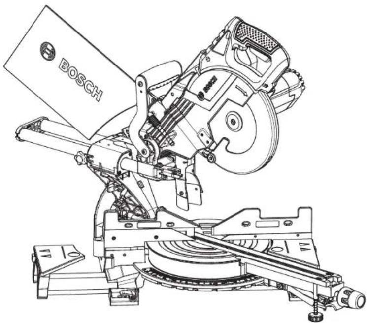
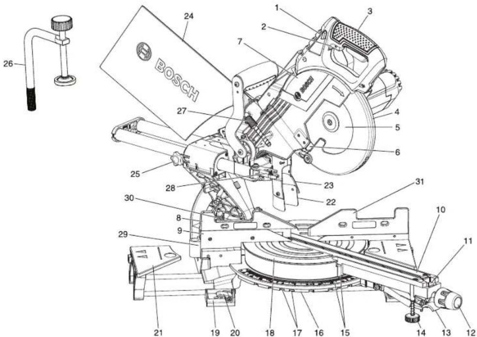
Getting To Know Your Miter Saw
text_image
BOSCH 24 1 2 3 7 4 5 6 27 25 28 30 8 9 29 21 19 20 18 17 16 15 14 13 12 31 22 23 10 11WARNING To avoid injury from accidental starting, remove plug from power source outlet before making any adjustments.
-
Switch Lock-OFF Release Buttons – One of these two buttons must be pressed before the power switch can be pressed.
-
Power Switch – The power switch used with the switch "Lock-OFF" release button energizes the unit.
-
Main Handle - This handle contains the power switch. Pulling this handle down lowers the blade into the workpiece.
-
Lower Blade Guard – The lower blade guard helps protect your hands from the spinning blade. It retracts as the blade is lowered.
-
Blade - Use only 8 12 (216 mm) diameter blades with 38 (15.88 mm) diameter arbor holes.
-
Chip Deflector – Deflects cut-off workpieces from entering the upper guard.
-
Upper Guard - Covers upper portion of the blade.
-
Left Sliding Fence – Supports the workpiece. The fence also has holes to secure an auxiliary fence if desired.
-
Stationary Fence – Stationary fence is bolted to the base and will support the workpiece when the sliding fence is removed.
-
Kerf Inserts - Kerf inserts can be adjusted to different blade widths to minimize workpiece tear-out.
-
Miter Detent Override – Allows detent action to be locked out, allowing for micro-adjustments to any miter angle.
-
Miter Lock Knob – The miter lock knob locks the miter saw table at any desired miter angle.
-
Miter Detent Lever – The lever releases the table from the detent.
-
Front Stabilizing Foot - Provides additional support and stability when making slide cuts.
-
Miter Scale/Miter Pointer - The pointer rotates with the table and blade. It points to the miter scale to indicate the angle setting before a cut is made.
-
Miter Detent Plate – The position of the plate can be adjusted to set the accuracy of its detent locations.
-
Miter Detents - There are ten (10) miter detent slots for fast and accurate miter cuts of common miter angles.
-
Table - Sits in base, provides workpiece support, rotates for desired miter cuts and rotates the head assembly. The front extended part of the table is called the miter arm.
-
Tool Mounting Pads – The four corners of the saw provide areas to clamp, bolt or nail the saw to a flat work surface.
NOTE: To view items 20 through 30, see page 12.
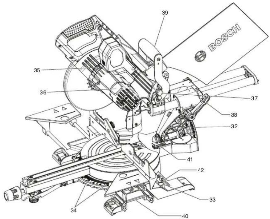
Getting To Know Your Miter Saw
text_image
BOSCH 39 35 36 37 38 32 41 42 33 34 40-
Base Extension Clamping Levers – Lock the base extensions at the desired positions.
-
Sliding Base Extensions – Provide extra work support. Useful when cutting long workpieces.
-
Rubber Deflector – Attaches to bottom of chute. Deflects dust into the chute.
-
Dust Chute – Directs sawdust up and through the elbow and to the bag.
-
Dust Bag – Has a zipper at the bottom. Bag can be uncoupled for emptying.
-
Slide Rail Lock Knob - The slide rail lock knob locks the slide rail when you are not making slide cuts and when you are transporting the saw.
-
Clamp - Use to hold the workpiece to the table and base, insert into clamp post location (item 32).
-
Depth Stop Screw - Turn the knob end to adjust the blade depth for cutting grooves.
-
Depth Stop Plate – Plate can be swung out to limit the depth of the blade travel.
-
60° Auxiliary Clamp Hole – used to appropriately clamp material at angles from 55° to 60° right.
-
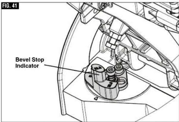
Left Bevel Stop indicator – allows you to set the most common bevel stops 0^ , 22.5^ , 33.9^ , 45^ and 47^ Left.
-
Right Sliding Fence - Supports the workpiece. The fence also has holes to secure an auxiliary fence if desired.
-
Bevel Scale and Pointers - Scale is large to allow user to easily read bevel angles. Pointer indicates what the current angle is.
-
Clamp Post Locations – Two vertical post holes in the base provided to insert the clamp (item 26).
-
Miter Detent Plate Screws - Four screws accessible through holes in the miter scale. These screws are loosened when adjusting position of the detent plate.
-
Arbor Lock - Press arbor lock button to keep blade from rotating when loosening or tightening arbor bolt during blade removal or installation.
-
Motor Cap - Provides access for inspecting and replacing brushes.
-
Head Assembly Lock Pin – Used to lock the head assembly in the lower position for transporting.
-
Bevel Lock Lever - The front-positioned bevel lock lever locks the head assembly at the desired bevel angle.
-
Top Carrying Handle - Used for lifting and transporting of saw.
-
Cast-in Carry Handles - Used for lifting and transporting of saw.
-
-2 Degree Bevel Stop – Can slide forward to allow for -2 degree bevel cuts.
-
5mm hex key – Used to change the blade and to make tool adjustments.
Cutting Capacities
| Key Moldings / Positioning Maximum Size | |
| Base Molding Against Fence* 2-3/4" | |
| 38° Crown Molding Angled Against Fence* 3-1/2" | |
| 45° Crown Molding Angled Against Fence* 3-3/4" | |
| Crown Molding Flat on Table 6-5/8" | |
| * Within miter range of 47° Left to 47° Right | |
| Miter / Bevel Maximum Height x Width | |
| 0°/ 0° 2-3/4" x 12-1/4" | |
| 45°/ 0° 2-3/4" x 8" | |
| 0°/ 45° (Left) 1-1/2" x 12-1/4" | |
| 45°/ 45° (Left) 1-1/2" x 8" | |
Assembly
▶ Unpacking and Checking Contents
Unpacking the Miter Saw - When removing this tool from packaging materials, reach down to the two side carry-handle locations and slowly lift until it clears the package.
WARNING
To avoid severe pinching, never lift or move this saw
by gripping any component of the mechanism support system.
Checking Contents in Package – Open the top of the package and look for the included loose parts. Refer to the diagram below.
WARNING
To avoid possible injury, always disconnect plug from
power source before performing any assembly, adjustments or repairs.
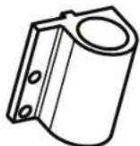
Loose Parts - 1 of each shown

Check off for each part

Workpiece Clamp
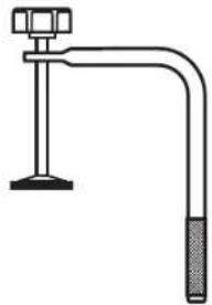
natural_image
Simple line drawing of a pipe clamp with a handle and base (no text or symbols)
Auxiliary Clamp Hole

Manual
Operating/Safety Instructions

BOSCH

Dust Bag
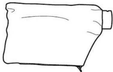
natural_image
Simple line drawing of a rolled-up fabric or paper piece (no text or symbols)
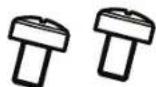
Screws for Auxiliary Clamp Hole

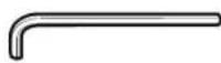
5mm Hex Key
Assembly
Tools Needed for Assembly and Alignment
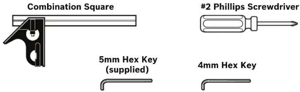
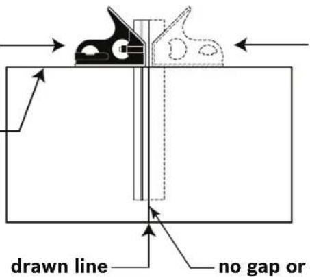
Combination Square Must Be True Checking Combination Square
- Position square and draw a light line
3/4" board with _ straight top edge
text_image
drawn line no gap or- Flip square (shown in dotted position)
- Check edge of flipped square against the drawn line. There should be no gap or overlap at the bottom end.
Assembly
▶ Attaching Loose Parts
WARNING
To avoid possible injury, disconnect plug from power source before performing any assembly, adjustments or repairs.
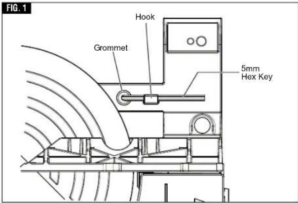
▼ STORING THE 5MM HEX KEY
There is a storage location on the saw to store the 5mm hex key. Insert the short leg of the hex key through the rubber grommet as shown. Rotate long leg under hook (see figure 1).
NOTE: The 5mm hex key is needed to change the blade and to make tool adjustments.
▼ATTACHING 60° AUXILIARY CLAMP HOLE
- Position the 60° auxiliary clamp hole as shown in figure 2.
- Insert the screws provided into holes and tighten with Philips screwdriver.
The 60° auxiliary clamp hole is used to appropriately clamp material at angles from 55° to 60° right see page 29 for clamping instructions.
text_image
FIG. 1 Hook Grommet 5mm Hex Key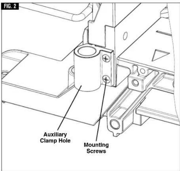
text_image
FIG. 2 Auxiliary Clamp Hole Mounting ScrewsAssembly
▶ Removing and Installing Blades
WARNING
To avoid possible injury, disconnect plug from power
source before performing any assembly, adjustments or repairs.
▼ REMOVING BLADE
- Press and hold the arbor lock (red button on opposite side of upper guard - item 35, page 12). Rotate the blade slowly while pressing the arbor lock until it fully seats into its lock position.
- Using the 5mm hex key, loosen the blade bolt by firmly turning it clockwise. NOTE: This bolt has left-hand threads.
- Remove the blade bolt and outer washer.
- Retract the lower blade guard and hold with one hand. Then carefully remove the blade by sliding the blade away from the inner washer and off the arbor shaft, then down and away from the saw. Leave the inner washer on the arbor shaft.
▼ INSTALLING 8-1/2" BLADE
WARNING
To avoid injury, do not use a blade larger or smaller than
8-1/2" diameter and 5/8" arbor. The blade's maximum plate thickness is 0.070".
WARNING
To reduce risk of injury, use saw blade rated 5600/min
(RPM) or greater.
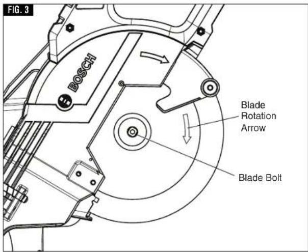
- Carefully handle the new blade. Check that the rotation arrow on the blade matches the rotation arrow on the lower guard. Slide the blade up and between the sides of the chip deflector and over the arbor shaft. Move the blade so its arbor hole goes around the support ring of the inner washer (see figures 3 and 4).
- Place the outer washer over the arbor shaft and finger-tighten the blade bolt (counterclockwise). Check that the blade remained on the inner washer's support ring.
- Rotate the blade slowly while pressing the arbor lock until it fully seats into its lock position.
- Using the 5mm hex key, firmly tighten the blade bolt counterclockwise. NOTE: This bolt has left-hand threads. Do not over tighten.
- Be sure the arbor lock is released so the blade turns freely.
- Place the 5mm hex key back in storage area.
WARNING
After installing a new blade, make sure the blade does not
interfere with the table insert at 0° and 45° bevel positions. Lower the blade into the blade slot and check for any contact with the base or turntable structure. If the blade contacts base or table, seek authorized service.
text_image
FIG. 3 BOSCH Blade Rotation Arrow Blade Bolt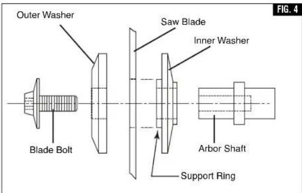
text_image
Outer Washer Blade Bolt Saw Blade Inner Washer Arbor Shaft Support Ring FIG. 4Assembly
▶ Assembling Dust Collection System
WARNING
To avoid possible injury, disconnect plug from power
source before performing any assembly, adjustments or repairs.
▼ ATTACHING THE DUST BAG
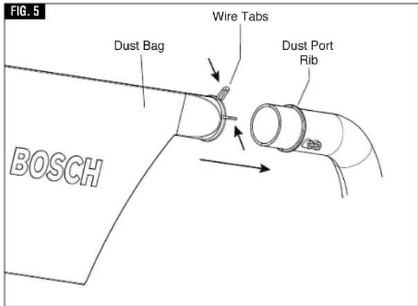
To attach the dust bag, squeeze the two wire tabs together and slide the dust bag over the dust port rib (see figure 5).
▼ USING AND CLEANING THE DUST BAG
Using Dust Bag – Attach the clean bag to the dust port.
Cleaning Dust Bag – After the dust bag is 2/3 to 3/4 full, remove it from the saw. Bring the bag to a proper container and pull open the zipper located on the bottom of the bag. Hold the bag by the coupler end and shake it vigorously until all the dust and debris fall from it. Close zipper and reattach the bag.
NOTE: Clean the bag at the end of the cutting session and before transporting or storing the saw.
WARNING
Be extremely careful when disposing of dust. Materials
in fine particle form may be explosive. Do not throw sawdust on an open fire. Spontaneous combustion, in time, may result from the mixture of oil or water with dust particles.
▼ ATTACHING A VACUUM CLEANER /DUST EXTRACTOR
The saw's dust port will accept the typical nozzles from 35 mm vacuum cleaner hoses, such as the VX120 that is included with the Bosch VH-Series hoses.
To connect the saw with a 1¼". or 1½" hose, the Bosch VAC002 or VAC024 adapters can be used (both sold separately). To connect the saw with a 2½" hose, the Bosch VAC020 (sold separately) should be used. Note: some 1½" hoses may fit over the exit port directly.
Attaching to Vacuum - Insert the vacuum nozzle into (or onto) the exit port as far as it will go (Fig. 6). Check to see that the vacuum hose is free from the mechanism and cutting path before plugging saw into power source.
▼ REPOSITIONING OR REMOVING THE RUBBER DEFLECTOR
The rubber deflector extends the range of dust and debris collection and should be left on the tool for maximum dust pickup efficiency, (figure 7). When slide cutting extra-tall materials (2-3/4" high), the rubber deflector will contact and flex over these materials. It will also contact and flex when the saw is pulled back before the cut. It will return to its original shape after the cut.
Repositioning Deflector - If the operator wants to avoid the contact of the rubber deflector with the material, the deflector can be temporarily folded
text_image
FIG. 5 Dust Bag Wire Tabs Dust Port Rib BOSCH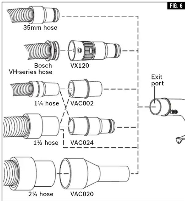
text_image
35mm hose Bosch VH-series hose VX120 1¼ hose VAC002 1½ hose VAC024 2½ hose VAC020 Exit port FIG. 6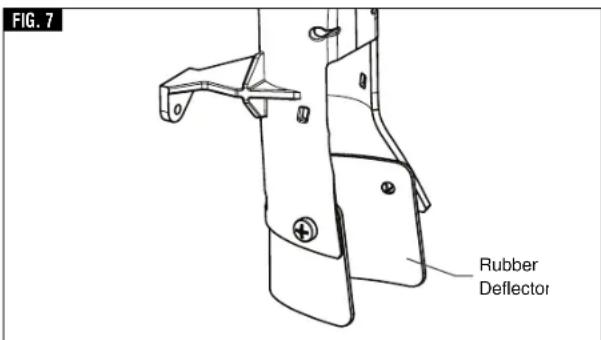
text_image
FIG. 7 Rubber Deflectorup and over the back of the dust chute. If the operator permanently wants no contact of the deflector with the material being cut, the deflector may be removed.
Assembly
▶ Using the Head Assembly Lock Pin
WARNING
To avoid possible injury, disconnect plug from power
source before performing any assembly, adjustments or repairs.
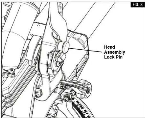
▼ HEAD ASSEMBLY LOCK PIN
The head assembly lock pin (figure 8) is used to hold the saw's head assembly in the DOWN position. This position prevents the head from bouncing up and down during transportation. This also makes the saw more compact for lifting and storage. This position is also required for some calibrating procedures.
▼ TO ENGAGE THE HEAD ASSEMBLY LOCK PIN:
- Check that the depth stop plate is disengaged, pressed in against saw head, (figure 9).
- Grasp the saw's main handle and press down on the head assembly.
- While pressing the saw head down, push in on the head assembly lock pin, (figure 8). Release the head assembly. The head will be locked in the DOWN position.
▼ TO DISENGAGE THE HEAD ASSEMBLY LOCK PIN:
- Grasp the main handle and press down on the head assembly.
- While pressing the head down, pull out the head assembly lock pin. Release the lock pin, but maintain your grip on the main handle. Slowly allow the spring-loaded saw head to come up to the top of its travel and then release the handle.
text_image
Head Assembly Lock Pin FIG. 8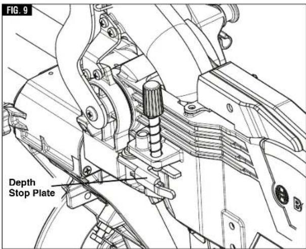
text_image
FIG. 9 Depth Stop PlateAdjustments
▶ Depth of Cut
WARNING To avoid possible injury, disconnect plug from power source before performing any assembly, adjustments or repairs.
When a new blade is installed, it may be necessary to check the clearance of the blade to the turntable structure. The depth stop plate is a feature provided to allow for (normal) full-depth cuts or non-through cuts used to cut grooves.
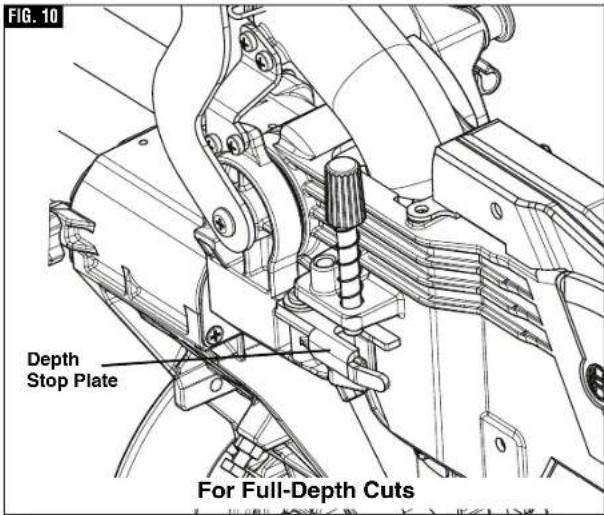
▼ SETTING BLADE DEPTH FOR NORMAL FULL-DEPTH CUTS
- When making normal full-depth cuts, push the depth stop plate in toward the saw head (see figure 10). This will allow the depth stop screw to pass through the hole in the plate.
- Check for full depth of cut:
a. Set table at 0^ miter and push saw fully back.
b. Pull out head assembly lock pin to the release position.
c. Push down saw head and watch the depth stop screw pass through the stop plate without any binding or contact with the plate.
▼ SETTING BLADE DEPTH FOR NON-THROUGH CUTS FOR CUTTING GROOVES
NOTE: For best results, Bosch recommends the use of a table saw with an optional dado blade set for cutting grooves and non-through cuts. In the event this is not available, the feature described below is a convenient alternative.
- Release (pull out) the head assembly lock pin and allow the saw head to move fully up. Slide saw head to the full back position.
- Pull the depth stop plate out away from the saw head (see figure 11).
-
Grip the main handle (item 3, page 11) and push down the saw head while watching the depth stop screw contact the top surface of the depth stop plate.
-
Turn the knob at the end of the depth stop screw (while the threaded end is in contact with stop plate) and watch the bottom of the saw blade move. This adjustment sets the depth of cut.
See page 38 for "Cutting Grooves" instructions.
text_image
FIG. 10 Depth Stop Plate For Full-Depth Cuts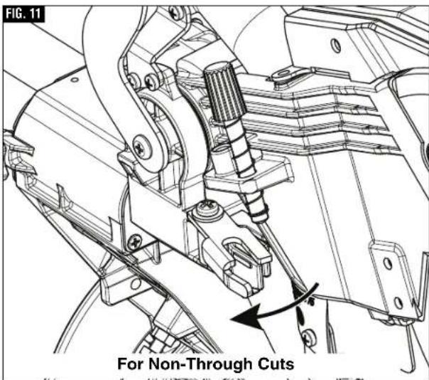
text_image
FIG. 11 For Non-Through CutsAdjustments
▶ Miter Detent System
WARNING
To avoid possible injury, disconnect plug from power
source before performing any assembly, adjustments or repairs.
▼ CALIBRATING MITER DETENT SYSTEM
- Engage the miter detent at the 0° position. Loosen the miter lock knob 1/2 turn.
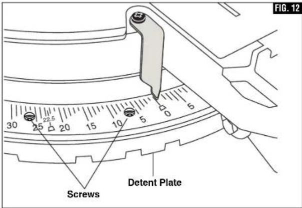
- Look for four round holes in the miter scale plate. In each hole is a screw. Use a Philips screwdriver to loosen all four screws 1 to 2 turns. This will loosen the miter detent plate (see figure 12).
- Slide the head assembly completely to the back and engage the slide rail lock knob by tightening the knob to the right (clockwise) (item 25 - page 12).
- Lock saw down using the head assembly lock pin (item 36 - page 12).
- Hold one side of a 90° combination square against the fence and rotate the table (and detent plate) until the side of the saw blade plate is in full contact with the other side of the square...do not contact the blade teeth with the square (figure 13).
- Tighten all four screws - loosen and reset the miter scale pointer to the "0" position.
▼ MITER SCALE POINTER ADJUSTMENT
- Rotate table to 0^ detent position and lock in place.
- Raise the head assembly to the full UP position.
- Loosen the pointer adjust screw that holds the miter scale pointer in place (see figure 14).
- Position the pointer to align with the 0^ line. Tighten the screw.
text_image
FIG. 12 Screws Detent Plate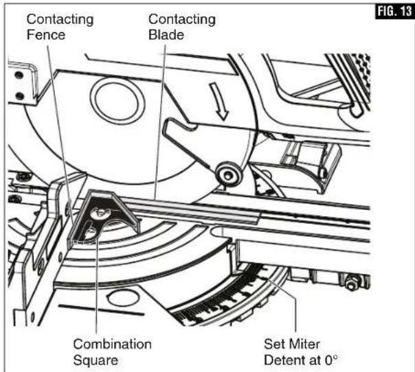
text_image
Contacting Fence Contacting Blade Combination Square Set Miter Detent at 0° FIG. 13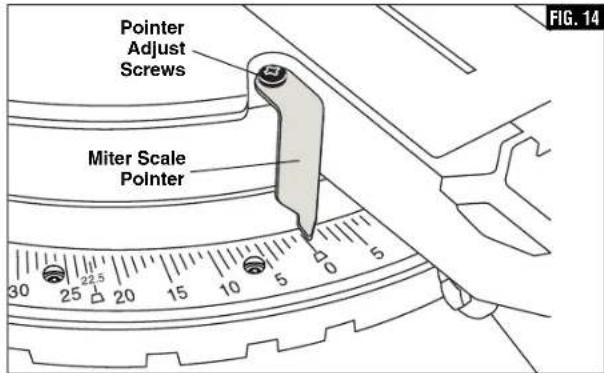
text_image
Pointer Adjust Screws Miter Scale Pointer 30 25 20 15 10 5 0 5 FIG. 14Adjustments
▶ Kerf Insert Adjustment
WARNING
To avoid possible injury, disconnect plug from power
source before performing any assembly, adjustments or repairs.
The kerf inserts should be adjusted close to the blade, but without touching the blade, to avoid tear-out on the bottom of the workpiece.
- Hold the saw head assembly down and push in the head assembly lock pin (item 36 - page 12) to keep the saw in the DOWN position.
- Loosen the four kerf screws using a 4mm Hex key, (figure 15).
- Adjust the kerf inserts as close to the blade (teeth) as possible without touching the blade.
- Tighten the kerf screws.
NOTE: At extreme bevel angles, the saw blade may slightly cut into kerf insert.
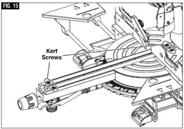
text_image
FIG. 15 Kerf Screws▶ 0° Bevel Stop
WARNING
To avoid possible injury, disconnect plug from power
source before performing any assembly, adjustments or repairs.
▼ CHECKING 0° BEVEL STOP SETTING
- Hold the saw head assembly down and push in the head assembly lock pin (item 36 - page 12) to keep the saw in the DOWN position.
- Slide the head assembly completely to the back and engage the slide rail lock knob by tightening the knob to the right (clockwise) (item 25 - page 9).
- Rotate the table to the 0^ miter position.
- Pull the bevel lock lever forward to unlock the head assembly.
- Tilt the saw assembly to the left (counterclockwise), then rotate to the right (clockwise) until you feel the stop in the vertical position. This is where the saw is currently set for 0° bevel cut.
- Use a combination square to check that the blade is 90^ (square) to the table. Place the square's ruler edge against the table and slide it to contact the blade with the vertical side of the square's head (see figure 16).
- Check that the saw blade's plate (not teeth) is touching the square's 90° side. If the saw blade's plate is not in full contact with the square's body 90° side, follow the "Calibrating Blade at 0° Bevel" procedures.
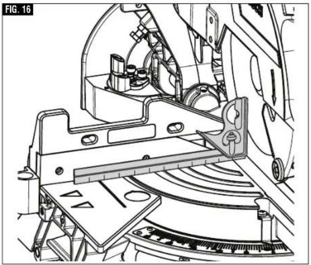
natural_image
Technical line drawing of a mechanical assembly with no visible text or symbolsAdjustments
▶ 0° Bevel Stop
WARNING
To avoid possible injury, disconnect plug from power source before performing any assembly, adjustments or repairs.
NOTE: Your miter saw was completely adjusted at the factory. However, during shipment, slight misalignment may have occurred. Check the following settings and adjust if necessary prior to using this miter saw.
▼ CALIBRATING BLADE AT 0° BEVEL (90° TO THE TABLE)
Note: Use a 3/8" (10mm) wrench for adjustment. Note: Calibrating the bevel setting automatically calibrates the -2° right stop.
- Lower head assembly and engage head assembly lock pin.
- Slide the head assembly completely to the back and engage the slide rail lock knob by tightening the knob to the right (clockwise).
- Pull the bevel lock lever forward to unlock the head assembly.
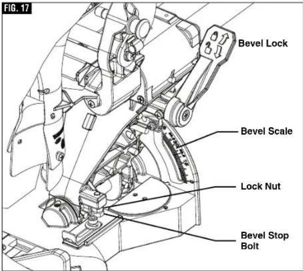
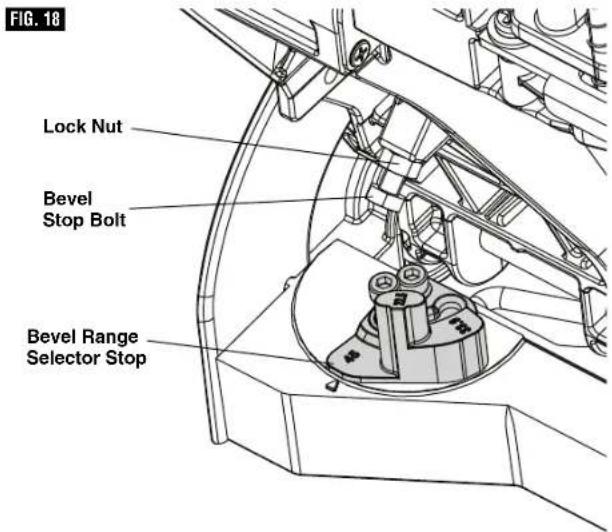
- Locate the bevel stop bolt below the bevel lock handle on the right side of the bevel post. This bolt features a lock nut (see figure 17).
- Loosen the bevel stop bolt a quarter turn and then loosen the lock nut. When this is complete you will be able to adjust the bevel stop bolt by hand.
A. Rotate the bevel stop bolt clockwise to adjust the head to the right.
B. Rotate the bevel stop bolt counter-clockwise to adjust the head to the left.
-
Follow the procedure in "Checking 0° Bevel Setting" to check your modifications. If further adjustment is required, repeat the steps above.
-
Once satisfactory, lock the bevel lock at 0^ to prevent movement.
- Finger tighten the lock nut in place. Once secured, tighten the lock nut with wrench.
▼ ADJUSTING BEVEL SCALE POINTER
Once you have adjusted the blade to the correct angle, make sure to adjust the Bevel Scale Pointer. To do so,
- Loosen the screw which holds the pointer in place a quarter turn, (see figure 18).
- Align the pointer with the 0^ line and retighten screw.
text_image
FIG. 17 Bevel Lock Bevel Scale Lock Nut Bevel Stop Bolt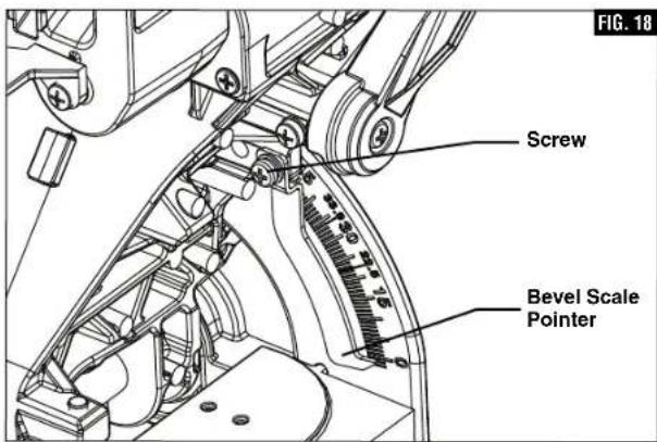
text_image
Screw Bevel Scale Pointer FIG. 18Adjustments
▶ 45° Bevel Stop
WARNING
To avoid possible injury, disconnect plug from power source before performing any assembly, adjustments or repairs.
▼ CHECKING LEFT 45° BEVEL ADJUSTMENT
- Lower head assembly and engage head assembly lock pin.
- Rotate table to 0^ miter position and lock.
- Slide the head assembly completely to the back and engage the slide rail lock knob by tightening the knob to the right (clockwise).
- Slide the fence completely to the left to avoid hitting it with the saw head.
- Pull bevel lock lever forward to unlock the head assembly.
- Check range of bevel range selector stop. It should be at 45^ , (figure 18).
- Tilt the saw assembly to the left until you feel it stop. This is where the saw is currently set for 45^ bevel cut.
- Use a combination square to check blade squareness to the table. Place the combination square on the table and press its 45^ surface against the blade. If the blade does not contact the full length of the square, follow the calibration procedure. (see figure 19)
▼ CALIBRATING BLADE AT LEFT 45° BEVEL
Note: Use a 3/8" (10mm) wrench for adjustment. Note: Calibrating the bevel setting automatically calibrates the 33.9°, 22.5°, and 45° left stop.
- Lower head assembly and engage head assembly lock pin.
- Slide the head assembly completely to the back and engage the slide rail lock knob by tightening the knob to the right (clockwise).
- Slide the fence completely to the left to avoid hitting it with the saw head.
-
Check bevel range selector stop located on the left side of the bevel post on the table. It should be at 45^ .
-
Pull the bevel lock lever forward to unlock the head assembly.
-
Locate the bevel stop bolt along the left side of the bevel post. This bolt features a lock nut. (figure 18)
-
Loosen the bevel stop bolt a quarter turn and then loosen the lock nut. When this is complete you will be able to adjust the bevel stop bolt by hand.
A. Rotate the bevel stop bolt clockwise to adjust the head to the lift.
B. Rotate the bevel stop bolt counter-clockwise to adjust the head to the right.
text_image
FIG. 18 Lock Nut Bevel Stop Bolt Bevel Range Selector Stop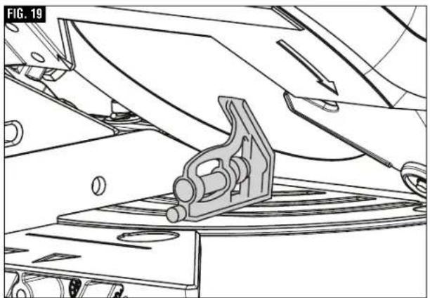
natural_image
Technical line drawing of a mechanical assembly with a bracket and mounting base (no text or symbols)-
Follow the procedure in "Checking Left 45° Bevel Adjustment" to check your modifications. If further adjustment is required, repeat the steps above.
-
Once satisfactory, lock the bevel lock lever at 45^ to prevent movement.
-
Finger tighten the lock nut in place. Once secured, tighten with wrench.
Transporting
WARNING
To avoid injury, follow all statements identified below
by the BULLET (•) symbol.
- Never lift this saw by grasping the base extensions when they are in the extended position.
- Unplug electric cord and wind up. Use the hook and loop strap to hold the wrapped cord together.
- Never lift the saw by gripping any of the mechanism parts. The saw may move and cause severe injuries to your fingers or hands.
• To avoid back injury, hold the tool close to your body when lifting. Bend your knees so you can lift with your legs, not your back. - Never lift tool by holding switch handle. This may cause serious damage to the tool.
- Never lift the miter saw by the power cord. Attempting to lift or carry the tool by the power cord will damage the insulation and the wire connections, resulting in electric shock or fire.
- Place the saw on a firm, level surface where there is plenty of room for handling and properly supporting the workpiece.
- ONLY lift this saw by the cast-in carry handles at each side of the bottom of the base or top carry handle.
▼ PREPARING TO LIFT THE SAW
- Set bevel angle at 0^ and lock in place using the bevel lock lever.
- Rotate the table to either 45^ or 0^ and lock into place using the miter lock knob.
- Lock the saw head in the DOWN position with the head assembly lock pin.
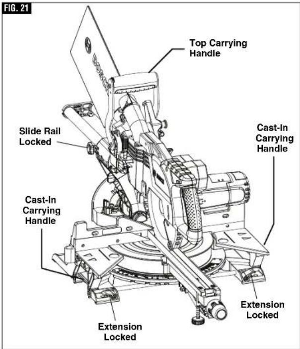
- Slide the head assembly completely to the front and engage the slide rail lock knob by tightening the knob to the right (clockwise) (figure 21).
- Check that each sliding base extension is in the closed and locked position, (figure 21).
▼ LIFT THE SAW BY THE TOP CARY HANDLE
Grasping the top carry handle with one hand lift the saw off the work surface see figure 22.
▼ LIFT THE SAW BY THE CAST IN CARRY HANDLES
With the saw facing you and the head mitered to a 45°, head assembly locked down, and the head in the forward position with the slide rail knob tightened. Grip both cast in carry handles located under the base table extension (see figure 21). Continue to lift and transport comfortably.
text_image
FIG. 21 Top Carrying Handle Slide Rail Locked Cast-In Carrying Handle Cast-In Carrying Handle Extension Locked Extension Locked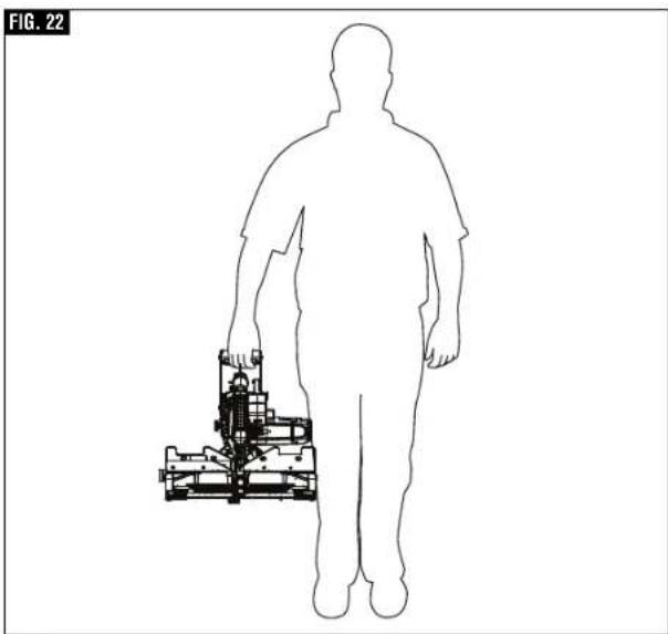
natural_image
Silhouette of a human figure holding a small mechanical device, labeled 'FIG. 22' (no text or symbols on the diagram itself)Placement and Mounting
WARNING
Be certain the miter saw is mounted or placed on a level,
firm work surface before using. A level and firm work surface reduces the risk of the miter saw becoming unstable.
▼ WORKBENCH PERMANENT ATTACHMENT
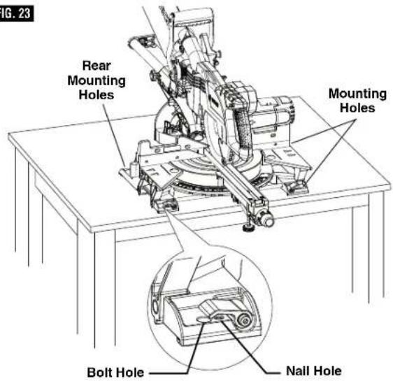
- Each of the four mounting holes should be bolted securely using 5/16" bolts, lock washers and hex nuts (not included).
- Locate and mark where the saw is to be mounted.
- Drill four 5/16" diameter holes through workbench.
- Place the miter saw on the workbench, aligning holes in base with holes drilled in workbench. Install bolts, lock washers and hex nuts (figure 23).
▼ ALTERNATE MOUNTING
The smaller mounting holes at each corner can be used for nails or longer drywall screws.
The supporting surface where the saw is to be mounted should be examined carefully after mounting to ensure that no movement can occur during use. If any tipping or walking is noted, secure the workbench or stand before operating the miter saw.
CAUTION
Be careful not to over-drive nail or over-torque the bolt.
This could crack foot or damage base.
▼ TEMPORARY MOUNTING USING CLAMPS
If necessary, clamp the miter saw to a workbench or table top.
Place two or more "C" clamps on the clamping areas and secure (see figure 24). There are clamping areas at all four corners of the saw.
Be careful not to place clamps over the base extension clamping levers (see figure 24).
Mounting with clamps may prevent access to some wide miter angles and locking of the sliding base extensions.
▼ MOUNTING TO BOSCH JOBSITE STANDS
This saw can also be mounted to a Bosch Jobsite stand, figure 25 (see page 49).
FIG. 23
text_image
Fig. 23 Rear Mounting Holes Mounting Holes Bolt Hole Nail Hole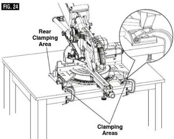
text_image
FIG. 24 Rear Clamping Area Clamping Areas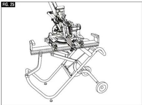
natural_image
Technical line drawing of a mechanical device with wheels and a cart (no text or symbols)Preparing for Saw Operations
▶ Switch Activation
For safety, the switch lever is designed to prevent accidental starts. To operate safety switch, slide the switch "Lock-OFF" release button with either thumb to disengage the lock, then pull the power switch trigger and release the switch "Lock-OFF" release button (figure 26). When the power switch trigger is released, the switch "Lock-OFF" release button will engage the power switch trigger automatically, and the lever will no longer operate until either "Lock-Off" release button is engaged again.
NOTE: Power switch trigger can accommodate a padlock with a long shackle of up to 3/16" in diameter (not provided with miter saw) to prevent unauthorized use.
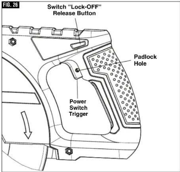
text_image
FIG. 26 Switch "Lock-OFF" Release Button Padlock Hole Power Switch Trigger▶ Body and Hand Position
WARNING
Position your body and hands properly to make safer. Failure to follow all fied below by bullet (•) in serious personal injury.
- Never place hands near cutting area. Keep hands outside the "No Hands Zone".
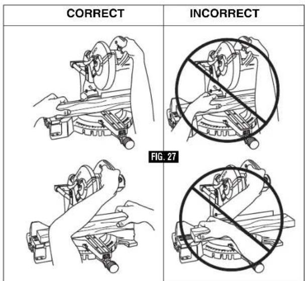
text_image
CORRECT INCORRECT FIG. 27The "No Hands Zone" is an area 6 inches wide on left and right side of the blade cutting path. Portion of the Fence in this are also considered a part of the "No Hands Zone".
The "No Hands Zone" for zero miter and zero bevel cuts is marked on the tool with lines and "No Hands" symbols – Figure 28 A.
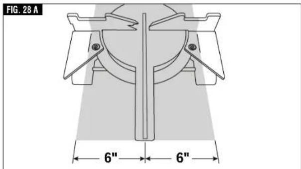
text_image
FIG. 28 A 6" 6"The "No Hands Zone" for all slide and miter right cuts is defined in Figure 28 B.
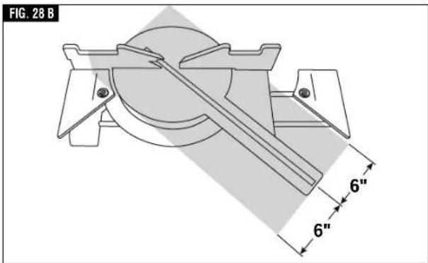
text_image
FIG. 28 B 6" 6"Preparing for Saw Operations
The "No Hands Zone" for all slide and miter left cuts is defined in Figure 28 C.
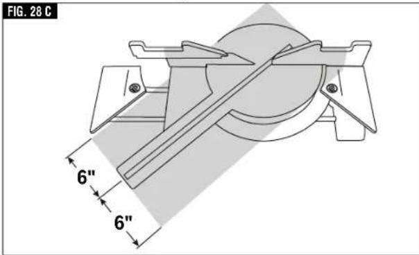
text_image
FIG. 28 C 6" 6"With all bevel cuts the "No Hands Zone" extends vertically up to the bottom of the upper guard when the head assembly is in the lowest cut position - Figure 28 D.
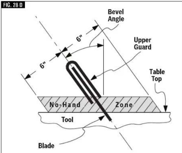
text_image
FIG. 28 D Bevel Angle Upper Guard Table Top 6" 6" No-Hand Zone Tool BladeUse sliding base extensions, sliding fence, and additional workpiece supports (see page 29) to properly support the workpiece and hold or clamp it outside of the "No Hands Zone".
Workpiece can be held against table and fence by hand only outside of the "No Hands Zone" – in figure 28.
WARNING Always ensure that there is adequate fence and base
support in the area where material is held by hand. If the workpiece must be held within the "No Hands Zone" then use clamp to securely hold the workpiece against the table and fence. Ensure that the clamp does not interfere with cutting operation – perform a dry run.
- Hold workpiece firmly to the fence to prevent movement.
- Keep hands in position until trigger has been released and blade has stopped completely.
- Keep feet firmly on the floor and maintain proper balance.
- Follow the miter arm when mitering left or right. Stand slightly to the side of the saw blade.
- Sight through the lower guard if following a pencil line.
- Before making any cut, with the power off, lower the blade to preview the blade path - dry run.
WARNING Be aware of the path of the saw blade. Make a dry run with the saw OFF by conducting a simulated cutting cycle, and observe the projected path of the saw blade. Keep hands at least six (6) inches away from the projected path of the saw blade.
DRY RUN — It is important to know where the blade will intersect with the workpiece during cutting operations. Always perform the simulated cutting sequence with the power tool switched OFF to gain an understanding of the projected path of the saw blade. Mentally note where the path of saw blade will fall and set up your work to keep your hands and arms at least six (6) inches away from the projected path of the spinning blade. Adjust your clamps and fences so that the smooth lower guard and cutting action is not interfered with during cutting operation.
Preparing for Saw Operations
▶ Workpiece Support
▼ CLAMPS
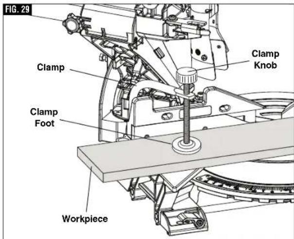
This clamp easily secures a workpiece to the table or base, figure 29.
- Insert the clamp's knurled bar down into a clamp post hole, there are two post holes located in the base behind the fence. The knurled end must be in the post at least 1/2". The 60° Auxiliary Clamp Hole is used to clamp material at angles from 55° to 60° right (figure 30). For installation instructions see page 16.
- Slide the clamp down until its rubber foot contacts the workpiece.
- Adjust the clamp height so it does not touch the sliding fence.
- Rotate the clamp's knob until the workpiece is firmly held in place.
- Move saw head up and down and forward and back to be sure it clears the clamp.
WARNING
There may be extreme compound cuts where clamp
cannot be used. Support workpiece with your hand outside the "No Hands" zone. Do not try to cut short pieces that cannot be clamped and cause your hand to be in the "No Hands" zone.
WARNING
Be aware of the path of the saw blade. Make a dry run
with the saw Off by conducting a simulated cutting cycle, and observe the projected path of the saw blade. Keep hands at least six (6) inches away from the projected path of the saw blade.
Other hold-down devices such as C-clamps can be used to hold the workpiece firmly against the table and the fence. Make sure the clamps are clear of the cutting path.
text_image
FIG. 29 Clamp Clamp Knob Clamp Foot Workpiece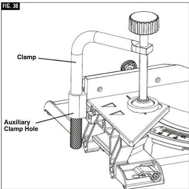
text_image
FIG. 30 Clamp Auxiliary Clamp HolePreparing for Saw Operations
▼ SLIDING FENCES
WARNING
To provide sufficient (minimum 6") spacing from hand to saw blade, extend the sliding fences and base extensions when making extreme bevel, miter or compound cuts.
▼ OPERATING SLIDING FENCES
- Loosen the fence lock knob counter clockwise 12 turn to loosen fence (see figure 32).
- Slide fence to the desired position.
- Tighten the lock knob clockwise to lock fence position.
▼ REMOVING SLIDING FENCES
The sliding fence may need to be removed when preforming extreme bevel cuts and most compound cuts.
- Loosen the fence lock knob counter clockwise 4 rotations, see figure 32.
- Lift and remove fence.
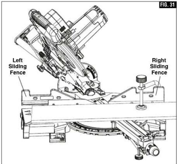
text_image
FIG. 31 Left Sliding Fence Right Sliding Fence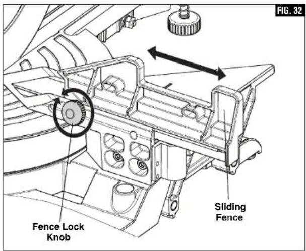
text_image
FIG. 32 Fence Lock Knob Sliding FencePreparing for Saw Operations
▶ Workpiece Support
▼ LONG WORKPIECE SUPPORT
WARNING
Long workpieces have a tendency to tip over unless
clamped down and properly supported from underneath.
WARNING
Do not use another person as a substitute for a table
extension or as additional support. Unstable support for the workpiece can cause the blade to bind or the workpiece to shift during the cutting operation, causing you to contact the spinning blade.
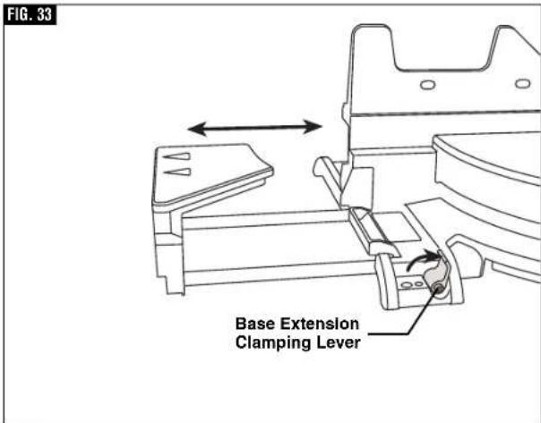
Operating Sliding Base Extensions - These extensions provide extra workpiece support and are especially useful when cutting long workpieces. To reposition the extensions, simply unlock the base extension clamping levers, reposition the extensions and lock the levers (see figure 33). The right extension lock lever tightens by rotating clockwise and the left lock lever tightens by rotating counterclockwise.
▼ ADDITIONAL WORKPIECE SUPPORT
Blocks - Long pieces need extra support. The base height is 3-7/16 inches. Cut two 2x4 pieces to 3-7/16" in length and fasten together. Boards of this thickness and height can be used to create auxiliary support extensions for long workpieces, figure 34.
WARNING
Always ensure that supporting surfaces are able
to properly support the workpiece and allow for secure holding by hand outside of the "No Hand Zone", or clamping with a clamp inside or outside of the "No Hand Zone" – see page 27 for "No Hand Zone" and appropriate hand positions.
WARNING
Always adjust the sliding base extension to support
workpiece. Unsupported workpiece can move out of position during cut and cause injury and/or tool damage.
text_image
FIG. 33 Base Extension Clamping Lever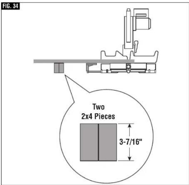
text_image
FIG. 34 Two 2x4 Pieces 3-7/16"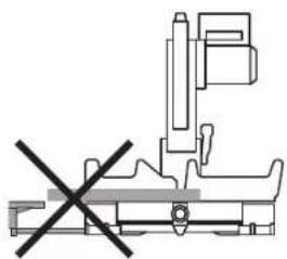
natural_image
Pure mechanical assembly diagram without any text, numbers, or symbols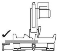
natural_image
Technical line drawing of a mechanical assembly with no visible text or symbolsWARNING
Be aware of the path of the saw blade. Make a dry run
with the saw Off by conducting a simulated cutting cycle, and observe the projected path of the saw blade. Keep hands at least six (6) inches away from the projected path of the saw blade.
Saw Operations
▶ Miter Detent System
▼ USING MITER DETENT SYSTEM
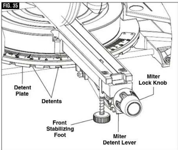
- Loosen the miter lock knob about 1/2 turn (see figure 35).
- Grip the lock knob, and then reach down with your index finger to pull up on the miter detent lever – pull lever until it is out from the miter detent plate.
- While gripping the miter lock knob and miter detent lever, rotate the saw's table. Stop table rotation at the desired angle as indicated by the miter scale pointer.
- Release the miter detent lever into a detent in the miter detent plate or at an angle between detents. If close to a miter detent, use the miter detent override feature.
- Tighten the miter lock knob before cutting. NOTE: It is recommended to tighten the miter lock knob before all cuts. It is required to tighten the knob before cutting at any angle between detents or when the miter detent override system is in use.
▼ MITER DETENT OVERRIDE
The miter detent override feature allows the miter detent action to be locked out, allowing for micro adjustments at any miter angle. When the desired miter angle is too close to a standard mitering angle that has a detent slot, this feature prevents the wedge on the miter detent lever from slipping into the detent slot on the miter detent plate.
- Lift and hold the miter detent lever.
- Push the detent override clip forward and latch in place over clip edge. Release miter detent lever (figure 36).
- Rotate table to any position on the miter scale.
- Lock the miter lock knob to retain miter position.
To Disengage:
Loosen miter lock knob and lift the miter detent lever to release the detent override clip. The clip should automatically disengage and the table should lock into any desired miter detent.
▼ ADJUSTING FRONT STABILIZING FOOT
The front stabilizing foot is located at the front of the saws table near the detent override (figure 36) this foot provides additional support and stability when making slide cuts. To adjust the foot to the work surface follow these steps:
-
Place the saw on the intended work surface.
-
Set desired miter angle.
-
Unscrew (turn counter clockwise) the front stabilizing foot until it contacts the work surface.
-
Screw in (turn clockwise) the front stabilizing foot if it prevents the tool from making full contact (all four base feet touching) with the work surface.
text_image
FIG. 35 Detent Plate Detents Front Stabilizing Foot Miter Detent Lever Miter Lock Knob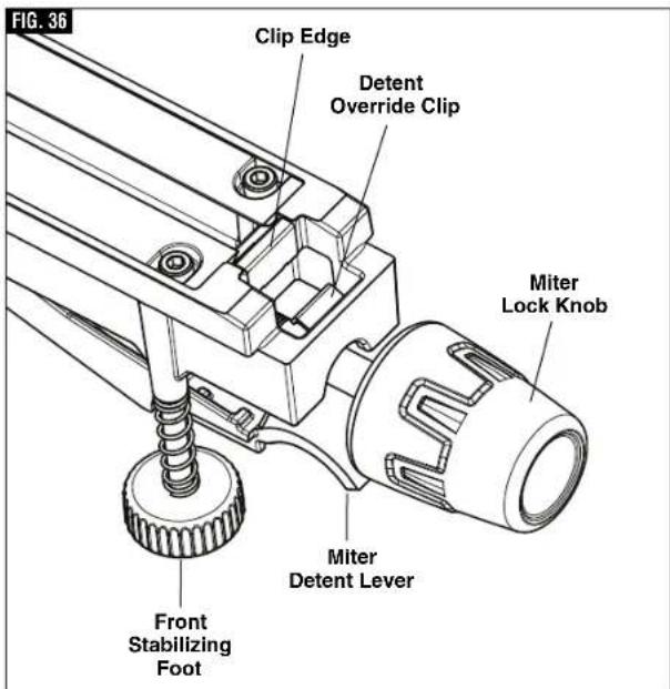
text_image
FIG. 36 Clip Edge Detent Override Clip Miter Lock Knob Miter Detent Lever Front Stabilizing FootNote: if the saw is firmly attached to a bench using all mounting holes the front stabilizing foot can be adjusted clockwise into the saw and does not need to be adjusted to the work surface (refer to page 26, How to mount the saw to a bench).
Saw Operations
▶ Chop Cut
- A “chop cut” is a cross-cut made when the saw is held to the rearmost position and is operated like a conventional (non-sliding) miter saw. Using the chop cut method lowers the cross-cutting capacity; however, many users prefer using this method because it is quicker when making repeat cuts. This method can also produce more accurate cuts because the saw head is locked in the retracted position.
- This saw has bevel angle stops that accurately stop at critical angles: 45° Left/Right and 0° Right. It comes factory-set and should not require adjustment. However, after extensive use or if the tool has received a hard impact, it may require an adjustment.
- A chop cut can cut pieces with a width of 5-1/2" or less
▼ MAKING A CHOP CUT
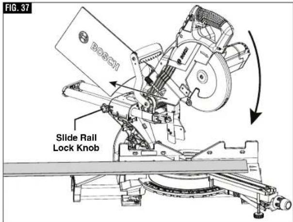
- Slide the head assembly to the rear as far as it will go (figure 37).
- Tighten the slide rail lock knob.
- Properly position workpiece. Make sure workpiece is clamped firmly against the table and the fence. Use clamping position that does not interfere with operation. Before switching on, lower head assembly to make sure clamp clears guard and head assembly.
WARNING
Use clamping position that does not interfere with
operation. Before switching "ON", lower head assembly to make sure clamp clears guard and head assembly.
text_image
FIG. 37 BOSCH Slide Rail Lock KnobWARNING
Be aware of the path of the saw blade. Make a dry run
with the saw Off by conducting a simulated cutting cycle, and observe the projected path of the saw blade. Keep hands at least six (6) inches away from the projected path of the saw blade.
- Activate the switch. Lower the head assembly and make your cut.
- Wait until blade comes to a complete stop before returning head assembly to the raised position and/or removing workpiece.
Saw Operations
▶ Slide Cut
- A “slide cut” is made with the head assembly unlocked and able to move away from the fence. This movement is supported and precisely controlled by the axial glide system. The maximum cross-cutting capacity is utilized by using this method.
- A slide cut is best used for cross-cutting workpieces wider than can be done with a chop cut – pieces wider than 2-1/2" and up to a maximum width of 12-1/4" across.
WARNING
NEVER pull the saw toward you during a cut. The blade can suddenly climb the workpiece causing KICKBACK.
▼ MAKING A SLIDE CUT
- Properly position workpiece. Make sure workpiece is clamped firmly against the table and the fence.
Use clamping position that does not interfere with operation. Before switching tool on, lower head assembly to make sure clamp clears guard and head assembly.
- Loosen the slide rail lock knob.
WARNING
Use a clamping position that does not interfere with
operation. Before switching "ON", lower head assembly to make sure clamp clears guard and head assembly.
WARNING
Be aware of the path of the saw blade. Make a dry run by conducting a simulated with the saw Off by conducting a simulated cutting cycle, and observe the projected path of the saw blade. Keep hands at least six (6) inches away from the projected path of the saw blade.
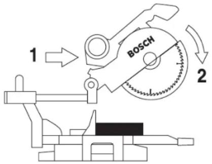
FIG. 38
text_image
1 BOSCH 2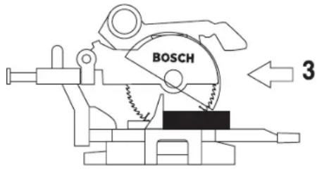
text_image
BOSCH 3- Grasp the switch handle and pull the head assembly away from the fence, until the blade clears the workpiece or to its maximum extension if blade cannot clear the workpiece (figure 38).
- Activate the switch. Lower the assembly all the way down and cut through the edge of the workpiece.
- Push (but do not force) the head assembly towards the fence to the full rear position to complete the cut.
- Wait until blade comes to a complete stop before returning head assembly to the raised position and/or removing workpiece.
Saw Operations
▶ Miter Cuts
- A "miter cut" is a cross-cut made with the blade perpendicular to the horizontal table. The blade is not tilted and the bevel pointer is on the 0^ line.
- Miter cuts can be made at any angle across a workpiece within this saw's range, from 52^ left to 60^ right.
- The miter scale shows the angle of the blade relative to the saw's fence. The miter pointer is attached to the table and indicates the saw's miter position before the cut is made.
- Ten positive miter detents are provided for fast and accurate preset miter angles – locatios are at 45°, 31.6°, 22.5°, 15° left and right, and center at 0°. The right side has an additional miter detent of 60°.
- The crown molding detents on the left and right are at 31.6° for compound cutting 38° “spring angle” crown molding lying flat on the table (see Cutting Crown Molding on page 39).
- For precision settings at miter angles very close to the miter detents, use the miter detent override to prevent the detent from automatically engaging the detent slot. See detent override instructions on page 32.
- A miter cut can be made either as a chop cut or slide cut, depending on the width of the workpiece.
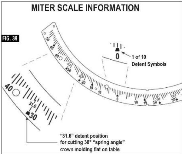
text_image
MITER SCALE INFORMATION FIG. 39 1 of 10 Detent Symbols "31.6" detent position for cutting 38° "spring angle" crown molding flat on table- The kerf inserts should be adjusted to be as close to the blade as possible to reduce splintering (see kerf insert adjustment instructions on page 22).
▼ READING THE MITER SCALE
The miter scale used on this saw includes several scales of information to help the user accurately preset this saw before making the cuts (see figure 39).
▼ MAKING A MITER CUT
- Loosen miter lock knob. Lift miter detent lever and move the saw to the desired angle, using either the detents or the miter scale. Tighten miter lock knob (figure 40).
- Extend the base extensions and fence on the side on which the cut will be made. (See Sliding Fence and Base Extension on pages 30 and 31).
- Properly position workpiece. Make sure workpiece is clamped firmly against the table or the fence. Use clamping position that does not interfere with operation. Before switching on, lower head assembly to make sure clamp clears guard and head assembly.
WARNING
Be aware of the path of the saw blade. Make a dry run with the saw Off by conducting a simulated cutting cycle, and observe the projected path of the saw blade. Keep hands at least six (6) inches away from the projected path of the saw blade.
- Follow procedures for either chop cut or slide cut (see page 33).
- Wait until blade comes to a complete stop before returning head assembly to the raised position and/or removing workpiece.
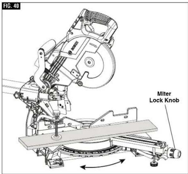
text_image
FIG. 40 Miter Lock KnobSaw Operations
▶ Bevel Cuts
A "bevel cut" is a cross-cut made with the blade perpendicular to the fence and with the table set at 0° miter. The blade can be tilted at any angle within the saw's range: 47° left and -2° right from the vertical.
The bevel scale is sized and positioned for easy reading. And the side bevel lock lever is to lock and unlock the various settings.
A rotating Left Bevel Stop indicator allows you to set the most common bevel stops 0°, 22.5°, 33.9°, 45° and 47° Left, (figure 41). The 33.9° bevel stop is for cutting 38° “spring angle” crown molding flat on the table. (See Compound Cuts for more information.)
A -2° Right Bevel Stop is also available for back cutting applications. Simply slide this stop forward and back to engage the 0° stop and disengage for -2° stop. (see figure 42)
▼ SETTING THE SAW TO MAKE A BEVEL CUT
- Extend the left base extension and left sliding fence (See "Sliding Fence and Base Extension" on pages 30 and 31)
Note: Be sure to move left sliding fence away from the blade to avoid cutting into the fence when bevel cutting. The left sliding fence may need to be removed when performing extreme bevel cuts and most compound cuts (see page 30). - With one hand, pull the bevel lock lever forward to unlock the saw head. (see figure 42)
- Adjust your left bevel stop to one of the three pre-set locations 22.5°, 33.9°, 45° and 47° Left, if desired, tilt head left until you reach the desired angle on your bevel scale. (see figure 42)
- Lock the bevel lock by pushing it toward the back of the saw.
- Follow procedures for either chop cut or slide cut (see page 33).
text_image
FIG. 41 Bevel Stop Indicator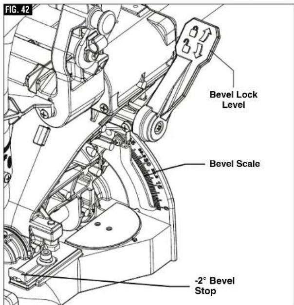
text_image
FIG. 42 Bevel Lock Level Bevel Scale -2° Bevel StopSaw Operations
▶ Compound Cuts
A "compound cut" is a cross-cut made with the blade both at a miter angle and at a bevel angle. Because it may take several tries to obtain the desired compound angle, perform test cuts on scrap material before making your cut.
▼ FOLLOW THESE INSTRUCTIONS FOR MAKING YOUR COMPOUND CUT:
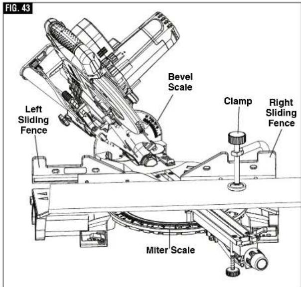
- Extend the left base extension and left sliding fence (See "Sliding Fence and Base Extension" on pages 30 and 31)
- Properly position workpiece. Make sure workpiece is clamped firmly against the table or the fence (figure 43).
WARNING
Use clamping position that does not interfere with
operation. Before switching on, lower head assembly to make sure clamp clears guard and head assembly.
WARNING
Be aware of the path of the saw blade. Make a dry run
with the saw Off by conducting a simulated cutting cycle, and observe the projected path of the saw blade. Keep hands at least six (6) inches away from the projected path of the saw blade.
- Set miter and bevel angles according to the instructions on page 35 and 36 for miter and bevel cuts.
- Follow the procedures for chop cut or slide cut.
- Wait until blade comes to a complete stop before returning head assembly to the raised position and/or removing workpiece.
Cutting crown molding flat on the table requires compound cuts. See cutting crown molding section on page 39.
text_image
FIG. 43 Left Sliding Fence Bevel Scale Clamp Right Sliding Fence Miter ScaleSaw Operations
▶ Cutting Grooves
The depth stop adjustment is a feature used to limit blade depth when cutting grooves in the workpiece.
NOTE: Read and understand all instructions on page 20 in the Adjustments section on "Setting Blade Depth for Non-Through Cuts for Cutting Grooves."
NOTE: For best results, Bosch recommends the use of a table saw with an optional dado blade set for cutting grooves and non-through cuts. In the event this is not available, the feature described below is a convenient alternative.
A groove should be cut as a slide cut.
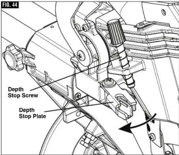
- For adjustment of groove depth, pull out depth stop plate and rotate depth stop screw. Rotating the depth stop screw clockwise will raise saw blade and rotating the screw counterclockwise will lower the blade (figure 44).
- For minor adjustments, simply rotate the depth stop screw to the desired location.
WARNING
Be aware of the path of the saw blade. Make a dry run
with the saw Off by conducting a simulated cutting cycle, and observe the projected path of the saw blade. Keep hands at least six (6) inches away from the projected path of the saw blade.
- Cut the two outside grooves first, figure 45.
- After cutting a groove, shut saw "OFF" and wait for blade to stop.
- To remove material between cuts, move the workpiece to the right or left. The saw must come to a complete stop before moving workpiece.
text_image
FIG. 44 Depth Stop Screw Depth Stop Plate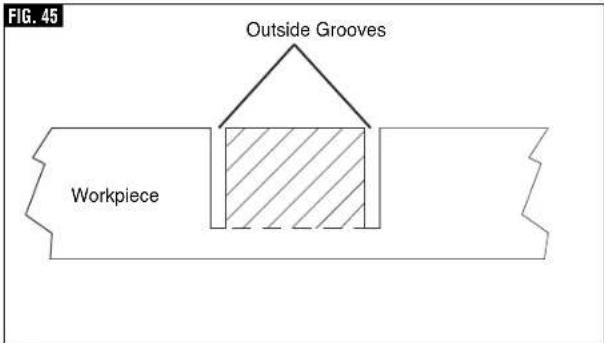
text_image
FIG. 45 Outside Grooves WorkpieceSaw Operations
▶ Cutting Base Molding
Base molding can be cut vertical against fence or flat on the table. The maximum size that can be vertical on the fence is 2-3/4", flat on table is 12-1/4". Cutting base molding can be done either as a
chop cut or a slide cut depending on the size of the workpiece.
Follow the table for helpful hints on cutting base molding for corners that have 90^ angles.
| BASE MOLDING CUTTING INSTRUCTIONS | |||||
| LOCATION OFMOLDING ON SAW → | Molding in Vertical Position:Back of molding is againstthe fence (up to 2-3/4") | Molding in HorizontalPosition: Back of molding is flaton the table (up to 12-1/4") | |||
| Bevel Angle Bevel→0° | Bevel = 45° | ||||
| Molding piece being cut → | To left ofcorner | To right ofcorner | To left ofcorner | To right ofcorner | |
Insidecorner of wall | Miter Angle | Left at 45° | Right at 45° | 0° | 0° |
| Positionof moldingon saw | Bottomagainst table | Bottomagainst table | Top againstfence | Bottomagainst fence | |
| Finished side | Keep leftside of cut | Keep rightside of cut | Keep leftside of cut | Keep leftside of cut | |
Outsidecorner of wall | Miter Angle | Right at 45° | Left at 45° | 0° | 0° |
| Positionof moldingon saw | Bottomagainst table | Bottomagainst table | Bottomagainst fence | Top againstfence | |
| Finished side | Keep rightside of cut | Keep rightside of cut | Keep rightside of cut | Keep rightside of cut | |
▶ Cutting Crown Molding
Crown molding cuts must be positioned properly to fit exactly.
There are two ways to cut crown molding: flat on table or angled to table and fence.
Crown molding's "spring angle" is the angle between the back of the molding and the bottom flat surface that fits against the wall.
This miter saw has special miter detents at 31.6° and bevel detents at 33.9°. These detents allow you to easily position most crown molding flat on the table and make precise cuts for 90° corners. NOTE: These detents cannot be used with 45° "spring angle" crown molding. These detents are only for use with crown molding that has a 38° "spring angle."
See also pages 40 and 41 for miter and bevel angle charts for cutting crown molding that has 38^ spring angles. Each chart lists the exact miter and bevel settings required for a wide range of corner angles.
Even though these angles are standards, most rooms do not have angles of exactly 90^ ; therefore, you will need to fine-tune your settings.
The optional Bosch DAF220K MiterFinder Digital Anglefinder/Protractor measures spring angles and corner angles, then automatically determines the exact miter and bevel settings necessary to make each crown molding cut fit perfectly.
Saw Operations
▶ Crown Molding Angled to Table and Fence
The preferred method for cutting crown molding with this saw is with the molding lying flat on the table. The advantage to cutting molding angled against fence is that no bevel setting is required, only the miter angle is adjusted.
The maximum crown molding width that can be cut and angled to table and fence is 3-1/2" at a 38 spring angle.
When cutting crown molding in this fashion it is recommended to purchase and use the optional Crown Stop Set.
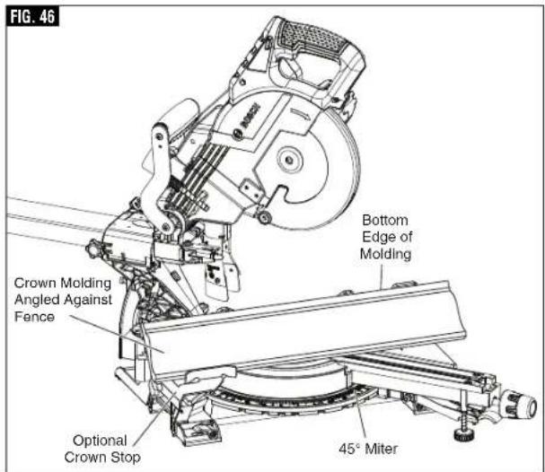
text_image
FIG. 46 Bottom Edge of Molding Crown Molding Angled Against Fence Optional Crown Stop 45° MiterFollow these instructions for cutting crown molding angled to table and fence:
- Position the molding so the bottom (decorative part, which is installed against the wall) is against the fence, figure 46.
- For 90° corner, set the miter angle using chart below. Tighten the miter lock knob.
- Support crown molding against the fence (see "Body and Hand Position" on page 27.)
WARNING
Be aware of the path of the saw blade. Make a dry run with the saw Off by conducting a simulated cutting cycle, and observe the projected path of the saw blade. Keep hands at least six (6) inches away from the projected path of the saw blade.
- Follow the procedures for chop or slide cut (see page 33).
- Wait until blade comes to a complete stop before returning head assembly to the raised position and/or removing workpiece.
NOTE: Always take a test cut using scrap to confirm correct angles.
▼ MITER AND BEVEL SETTINGS FOR STANDARD CROWN MOLDING CUTS
(When Workpiece Angled Against Fence)
Assumptions: Molding is milled consistently. Corner is 90°.
For other corner angles, divide actual measurement by 2.
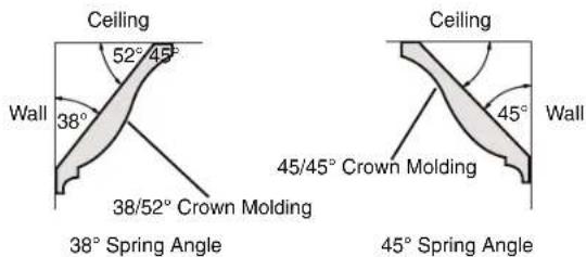
text_image
Ceiling 52° 45° Wall 38° 38/52° Crown Molding Ceiling 45° Wall 45/45° Crown Molding 38° Spring Angle 45° Spring Angle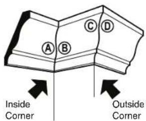
text_image
A B C D Inside Corner Outside CornerRefer to Chart
| For Any Crown Molding Up to 6" | ||
| Note: Always place bottom edge against fence | Miter (Table) Setting | Bevel (Tilt) Setting |
| Inside Corner - Left end A Use the left end of the cut | 45° Right | 0° Left |
| Right end B Use the right end of the cut | 45° Left | 0° Right |
| Outside Corner - Left end C Use the left end of the cut | 45° Left | 0° Right |
| Right end D Use the right end of the cut | 45° Right | 0° Left |
Cutting - Angled to Table and Fence
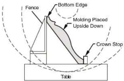
text_image
Fence Bottom Edge Molding Placed Upside Down Crown Stop TableSaw Operations
▶ Crown Molding Lying Flat on Table
"Spring angle" refers to angle between wall and crown molding.
Cutting crown molding flat on the table can be done either as a chop cut or a slide cut depending on the width of the workpiece.
Refer to special auxiliary fence for narrow cutoffs when cutting crown flat on table (see page 43).
FIG. 47
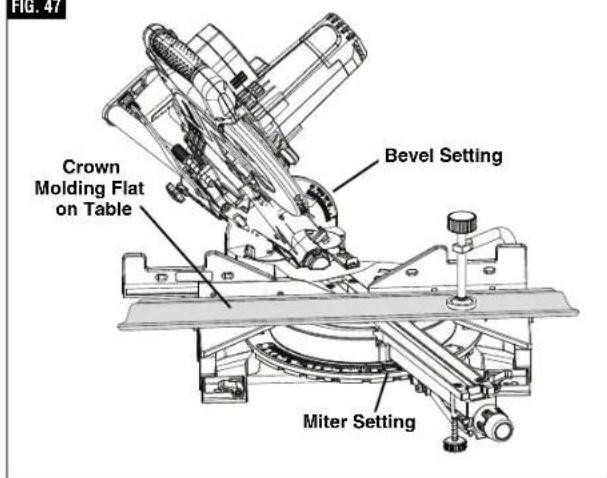
text_image
FIG. 47 Crown Molding Flat on Table Bevel Setting Miter SettingFollow these instructions for cutting crown molding lying flat on table:
- For 90° corner, set the bevel and miter angles using chart below. Tighten the miter lock knob and the bevel lock lever.
- Position molding with its back flat on saw table and correct edge against fence, then clamp in place. (figure 47)
WARNING
Use clamping position that does not interfere with
operation. Before switching "ON," lower head assembly to make sure clamp clears guard and head assembly.
WARNING
Be aware of the path of the saw blade. Make a dry run
with the saw Off by conducting a simulated cutting cycle, and observe the projected path of the saw blade. Keep hands at least six (6) inches away from the projected path of the saw blade.
- Follow procedures for either chop cut or slide cut (see page 33).
- Wait until blade comes to a complete stop before returning head assembly to the raised position and/or removing workpiece.
NOTE: Always take a test cut using scrap to confirm correct angles.
▼ MITER AND BEVEL SETTINGS FOR STANDARD CROWN MOLDING CUTS
(With Molding Flat on Table) Assumptions:
Molding is milled consistently. Corner is exactly 90°.
| Molding Spring Angle is 38° | ||
| Note: Always place top edge against fence | Miter (Table) Setting | Bevel (Tilt) Setting |
| Inside Corner - Left end A Use the left end of the cut | 31.6° Right | 33.9° Left |
| Right end B Use the right end of the cut | 31.6° Left | 33.9° Right |
| Outside Corner - Left end C Use the left end of the cut | 31.6° Left | 33.9° Right |
| Right end D Use the right end of the cut | 31.6° Right | 33.9° Left |
| Molding Spring Angle is 45° | ||
| Note: Always place top edge against fence | Miter (Table) Setting | Bevel (Tilt) Setting |
| Inside Corner - Left end A Use the left end of the cut | 35.3° Right | 30° Left |
| Right end B Use the right end of the cut | 35.3° Left | 30° Right |
| Outside Corner - Left end C Use the left end of the cut | 35.3° Left | 30° Right |
| Right end D Use the right end of the cut | 35.3° Right | 30° Left |
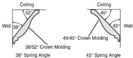
text_image
Ceiling 52° Wall 38° 38/52° Crown Molding Ceiling 45° 45° Wall 45/45° Crown Molding 38° Spring Angle 45° Spring Angle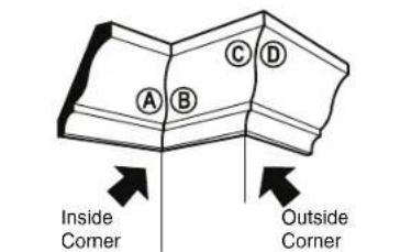
text_image
A B C D Inside Corner Outside Corner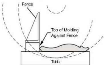
text_image
Fence Top of Molding Against Fence TableSaw Operations
▶ Auxiliary fence
▼ MAKING AN AUXILIARY FENCE:
Certain types of molding need a fence face extension because of the size and position of the workpiece. Holes are provided in the fence to attach an auxiliary fence. The auxiliary fence is used with the saw in the 0° bevel position only.
- Use 34 " thick piece of wood (plywood is preferd) to cut an auxiliary fence based on dimensions shown in Figure 49.
- Place the auxiliary fence against the miter saw fence (figure 48). Check that auxiliary fence does not interfere with head assembly. Check for interference between the auxiliary fence and the lower blade guard. Make adjustments as necessary.
WARNING
Check for interference between auxiliary fence and
saw head components by performing a dry run.
Fence interference can prevent proper saw operation and cause injury and/or tool damage.
- Mark the locations of the support holes on the wood from the back side of the fence (figure 48).
- Drill and countersink the holes on the front of the support board.
To fasten from front of fence:
- Attach auxiliary fence using four (4) 3/16" x 1-1/2" long flat head machine bolts. Secure behind metal fence with washer and #5 machine nuts.
WARNING
Be aware of the path of the saw blade. Make a dry run
with the saw Off by conducting a simulated cutting cycle, and observe the projected path of the saw blade. Keep hands at least six (6) inches away from the projected path of the saw blade.
- Make a full depth cut to create the blade slot.
To fasten from back of fence:
Use minimum 3/4" thick auxiliary fence and 1/4" round head wood screws (3/4" long).
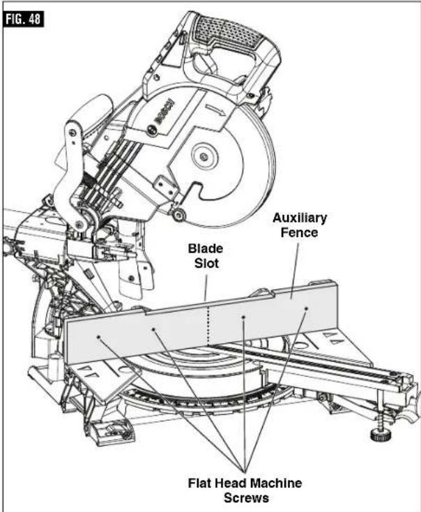
text_image
FIG. 48 Blade Slot Auxiliary Fence Flat Head Machine Screws- Drill four pilot holes through auxiliary fence and run screws from rear of metal fence.
WARNING
Be aware of the path of the saw blade. Make a dry run with the saw Off by conducting a simulated cutting cycle, and observe the projected path of the saw blade. Keep hands at least six (6) inches away from the projected path of the saw blade.
- Make a full depth cut to create the blade slot.
FIG. 49
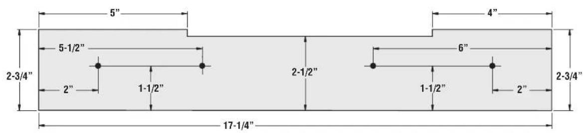
text_image
5" 4" 5-1/2" 6" 2-3/4" 2-1/2" 2" 1-1/2" 1-1/2" 2" 2-3/4" 17-1/4"Saw Operations
▶ Crown Molding Auxiliary Fence
WARNING
When making a compound cut on a molding lying flat on cut-off pieces (2" or less in selled at high speed over the back of the tool (see figure hence as instructed and shown
the table, narrow cut-off pieces (2" or less in width) may be propelled at high speed over the fence and beyond the back of the tool (see figure 50). Use auxiliary fence as instructed and shown in figures below.
A crown molding auxiliary fence is used to add support to the cut-off workpiece such as large crown molding when cut flat on the table (see figure 51). It will reduce splintering and movement of the unsupported cut-off piece of wood after the cut is made.
▼ MAKING CROWN MOLDING AUXILIARY FENCE:
Required pieces:
3/4" thick wood board
4 - Flat Head Machine Screws
1/4"diameter x 2-1/2" long
4 - 1/4" Flat Washers
4 - 1/4" Nuts
- Remove the sliding fence from the tool (see page 30).
- Build auxiliary fence by following the pattern and illustrations on page 42.
- Add 4 holes as dimensioned on pattern -or- add holes following the next steps:
a. Cut wood to the outside dimensions shown and temporarily attach to saw's stationary fence using two C-clamps.
b. Use 1/4" drill bit to drill first through existing holes in the rear of the stationary fence and then through the wood.
c. Remove wood, countersink the front of the wood and permanently attach to saw's fence with hardware shown below.
▼ FIRST-TIME USE OF THE AUXILIARY FENCE:
NOTE: The first time the auxiliary fence is used, it will be cut through by the saw blade - cutting through creates minimal clearance which reduces splintering on the workpiece. Set the miter angle and the bevel angle required before making the first cut.
WARNING
Be aware of the path of the saw blade. Make a dry run
with the saw Off by conducting a simulated cutting cycle, and observe the projected path of the saw blade. Keep hands at least six (6) inches away from the projected path of the saw blade.
Clamp the workpiece, then make cut - example: compound cutting large crown molding flat on the table.
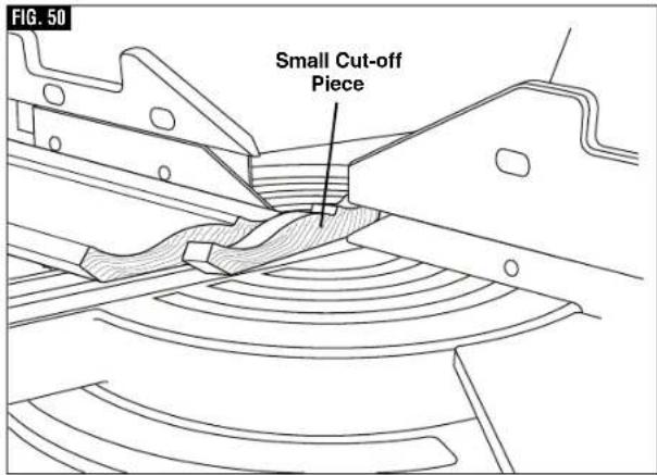
text_image
FIG. 50 Small Cut-off Piece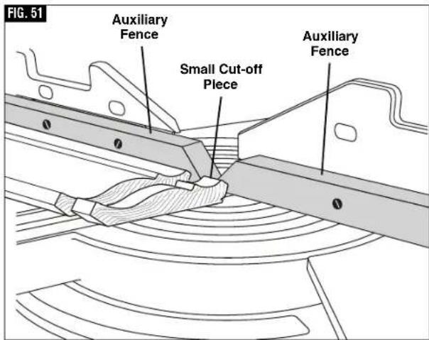
text_image
FIG. 51 Auxiliary Fence Small Cut-off Piece Auxiliary FenceSaw Operations
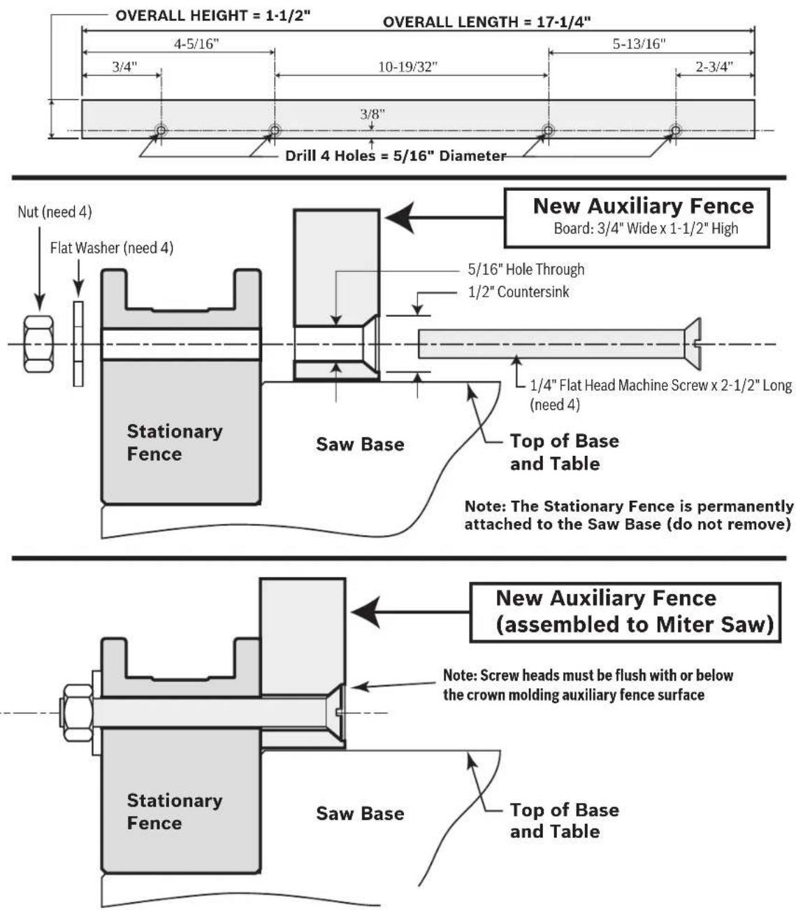
text_image
OVERALL HEIGHT = 1-1/2" 4-5/16" 3/4" 10-19/32" 5-13/16" 2-3/4" Drill 4 Holes = 5/16" Diameter OVERALL LENGTH = 17-1/4" Nut (need 4) Flat Washer (need 4) Stationary Fence Saw Base New Auxiliary Fence Board: 3/4" Wide x 1-1/2" High 5/16" Hole Through 1/2" Countersink 1/4" Flat Head Machine Screw x 2-1/2" Long (need 4) Top of Base and Table Note: The Stationary Fence is permanently attached to the Saw Base (do not remove) New Auxiliary Fence (assembled to Miter Saw) Note: Screw heads must be flush with or below the crown molding auxiliary fence surface Stationary Fence Saw Base Top of Base and TableSaw Operations
▶ Special Cuts
Cutting bowed material and round material are only two examples of special cuts.
WARNING
Use clamping position that does not interfere with operation. Before switching on, lower head assembly to make sure clamp clears guard and head assembly.
WARNING
Be aware of the path of the saw blade. Make a dry run with the saw Off by conducting a simulated cutting cycle, and observe the projected path of the saw blade. Keep hands at least six (6) inches away from the projected path of the saw blade.
WARNING
To provide sufficient (minimum 6") spacing from hand to saw blade, extend the sliding fence and base extensions when making extreme bevel, miter or compound cuts.
▼ CUTTING BOWED MATERIAL
If workpiece is bowed or warped, clamp it with the outside bowed face toward the fence. Always make certain that there is no gap between the workpiece, fence and table along the line of cut. Bent or warped workpieces can twist or rock and may cause binding on the spinning saw blade while cutting (figure 52).
▼ CUTTING ROUND OR IRREGULARLY SHAPED MATERIAL
For round material such as dowel rods or tubing, always use a clamp or a fixture designed to clamp the workpiece firmly against the fence and table. Rods have a tendency to roll while being cut, causing the blade to "bite" and pull the work with your hand into the blade (figure 53).
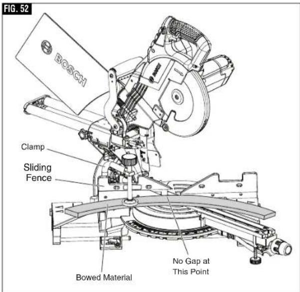
text_image
FIG. 52 BOSCH Clamp Sliding Fence Bowed Material No Gap at This Point
text_image
FIG. 53 BOSCH Clamp Sliding Fence Round MaterialMaintenance and Lubrication
▶ Service
WARNING
All tool service should be performed by a Bosch
Factory Service Center or an Authorized Bosch Service Station. Preventive maintenance performed by unauthorized personnel may result in misplacing of internal wires and components which could cause serious hazard.
▶ Motor Brushes
The brushes and commutator in your tool have been engineered for many hours of dependable service. To maintain peak efficiency of the motor, we recommend every 2-6 months the brushes be examined. Only genuine Bosch replacement brushes specially designed for your tool should be used.
▼ MOTOR BRUSH REPLACEMENT
To inspect or replace brushes:
- Unplug the saw.
- Loosen motor endcap screws, and remove motor endcap.
- Remove brush from brush holder by pulling back tension spring, then pull the brush out using the conecting wire, then unplug the terminal wire, figure 54.
NOTE: If installing the existing brush or brushes, make sure the brush goes in the same way it came out. Otherwise, a break-in period will occur that will reduce motor performance and increase brush wear.
- To reinstall new brushes follow steps in reverse.
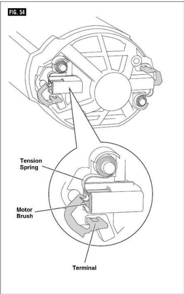
text_image
FIG. 54 Tension Spring Motor Brush TerminalMaintenance and Lubrication
WARNING
To avoid accidents, always disconnect the tool from the power supply before cleaning or performing any maintenance.
▶ Cleaning
CAUTION
Certain cleaning agents and solvents damage plastic
parts. Some of these are: gasoline, carbon tetrachloride, chlorinated cleaning solvents, ammonia and household detergents that contain ammonia.
Ventilation openings and switch levers must be kept clean and free of foreign matter. Do not attempt to clean by inserting pointed objects through openings.
Check regularly to make sure the lower guard and all moving parts are working properly.
▶ Care of Blades
Blades become dull even from cutting regular lumber. If you find yourself forcing the saw forward to cut instead of just guiding it through the cut, chances are the blade is dull or coated with wood pitch.
When cleaning gum and wood pitch from blade, unplug the saw and remove the blade. Remember, blades are designed to cut, so handle carefully. Wipe the blade with kerosene or similar solvent to remove the gum and pitch. Unless you are
experienced in sharpening blades, we recommend you do not try.
▶ Tool Lubrication
WARNING
Preventive maintenance performed by unauthorized
personnel may result in misplacing of internal wires and components which could cause serious hazard. We recommend that all tool service be performed by a Bosch factory Service Center or Authorized Bosch Service Station.
Your Bosch tool has been properly lubricated and is ready to use. It is recommended that tools with gears be regreased with a special gear lubricant at every brush change.
Periodically lubricate moving parts with a silicone, or light oil spray. Do not use grease because it tends to attract and hold sawdust.
▶ Bearings
All bearings in this tool are lubricated with a sufficient amount of high-grade lubricant for the life of the unit under normal operating conditions. No further lubrication is required.
Troubleshooting
▶ Troubleshooting Guide - Electrical
| PROBLEM | CAUSE | CORRECTIVE ACTION |
| Motor does not start. | 1. Check that unit is plugged in.2. Power source fuse or time delay fuse.3. Brushes worn.4. Other. | - Plug unit in. Use different outlet.- 15-Amp time delay fuse or circuit breaker.- See Motor Brush Replacement in the Maintenance and Lubrication section.- Authorized service. |
Troubleshooting
▶ Troubleshooting Guide - General
| PROBLEM | CAUSE | CORRECTIVE ACTION |
| Head assembly does not bevel to desired position. | Bevel lock is engaged. | - Pull the bevel lock forward to unlock the head assembly. |
| Blade hits table. 1. Misalignment. - Authorized service. | ||
| Angle of cut not accurate. 1. | Angle stops at 0° or 45° need adjustment. | - See Adjustments section (pages 20-24). |
| Cannot rotate table to change miter angle. | 1. Miter lock knob is tightened.2. Miter detent lever is engaged with a detent (slot) in detent plate.3. Sawdust accumulation. | - Turn miter lock knob counterclockwise to loosen.- Pull up on miter detent lever to disengage from detent slot (see page 32).- Vacuum or blow out dust around turntable; wear eye protection. |
| Head assembly will not fully raise or blade guard will not fully close. | 1. Head assembly lock pin is engaged.2. Sawdust accumulation.3. Sawdust accumulation. | - Pull out lock pin, allowing head assembly to go up (see page 19).- Clean head assembly.- Authorized service. |
| Blade binds, jams, burns wood. Rough cuts. | 1. Improper operation.2. Dull blade.3. Improper blade.4. Bent blade. | - See Saw Operations section.- Replace or sharpen blade.- Replace with 8-1/2" diameter blade designed for material being cut.- Replace blade. |
| Head assembly slides forward and back when making a chop cut. | Slide rail lock knob is disengaged. - Rotate Slide rail lock knob clockwise to lock head in place. | |
Troubleshooting
▶ Troubleshooting Guide - General
| PROBLEM | CAUSE | CORRECTIVE ACTION |
| Tool vibrates or shakes. 1. Saw blade not round.2. Saw blade damaged.3. Saw blade loose.4. Other | - Replace blade.- Replace blade.- Check that blade is properly seated on the inner washer.See Removing and Installing Blades on page 17.- Authorized service. | |
| Head assembly does not slide freely when attempting a slide cut. | 1. Slide rail lock knob is engaged. - Rotate slide rail lock knob counter clockwise to disengage. | |
| Blade does not cut completely through workpiece. | 1. Depth stop plate is pulled out for non-through cuts.2. Replacement blade is less than 8-1/2" diameter. | - Push depth stop plate inward to set for full-depth cuts (see page 20).- Change to a blade that is fully 8-1/2" diameter. |
| Saw blade or lower guard cuts or contacts left sliding fence when saw is set for bevel cuts. | 1. Left sliding fence is not moved out from path of saw blade before making bevel cut. | - Move left sliding fence to be clear of lower guard and saw blade; perform a "dry cut" to check for clearances before making bevel cuts (see page 37). |
Accessories and Attachments
- GAM220MF and GAM270MFL Digital Angle finder, Compound Cut Calculator, Protractor, and Level – Gives you the information needed to position cuts so that they fit together precisely even if the room is out of square.
-
MS1233 Crown Stop Set – Correctly hold crown molding in an inclined position against fence. Set molding for simple vertical cutting – no compound cutting required.
-
T1B Portable Miter Saw Stand
- GTA3800 Portable Miter Saw Stand with Wheels
- T4B Gravity-Rise Wheeled Miter Saw Stand
- MS1234 Length Stop
- Blades
▶Double isolation .....55
▶Rallonges .....55
Avoid positioning hands, fingers or arms
| Symbole Désignation / Explication | |
 | Designates Li-ion battery recycling program |
 | Designates Ni-Cad battery recycling program |
 | Alerts user to read manual |
 | Alerts user to wear eye protection |
 | This symbol designates that this tool is listed by Underwriters Laboratories. |
 | This symbol designates that this component is recognized by Underwriters Laboratories. |
 | This symbol designates that this tool is listed by Underwriters Laboratories, to United States and Canadian Standards. |
 | This symbol designates that this tool is listed by the Canadian Standards Association. |
 | This symbol designates that this tool is listed by the Canadian Standards Association, to United States and Canadian Standards. |
 Intertek Intertek | This symbol designates that this tool is listed by the Intertek Testing Services, to United States and Canadian Standards. |
 | This symbol designates that this tool complies to NOM Mexican Standards. |
natural_image
Simple line drawing of a faucet with a handle and base (no text or symbols)
text_image
Operating /Safety Instructions © BOSCH
natural_image
Simple line drawing of a cylindrical object with a protruding shaft (no text or symbols)
natural_image
Technical line drawing of a mechanical assembly with no visible text or symbolsnatural_image
Technical line drawing of a mechanical assembly with no visible text or symbolsnatural_image
Silhouette of a human figure standing with a small mechanical device on its back, labeled 'FIG. 22' (no text or symbols on the diagram itself)▼ SOULEVEZ LA SCIE PAR LES POIGNÉES INCORPORÉES LATÉRALES
natural_image
Technical line drawing of a mechanical device with wheels and a ladder (no text or symbols)text_image
CORRECT INCORRECTE FIG. 27natural_image
Mechanical assembly diagram with a cross symbol indicating no text or labels (no readable text or symbols)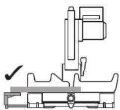
natural_image
Technical line drawing of a mechanical assembly with no visible text or symbols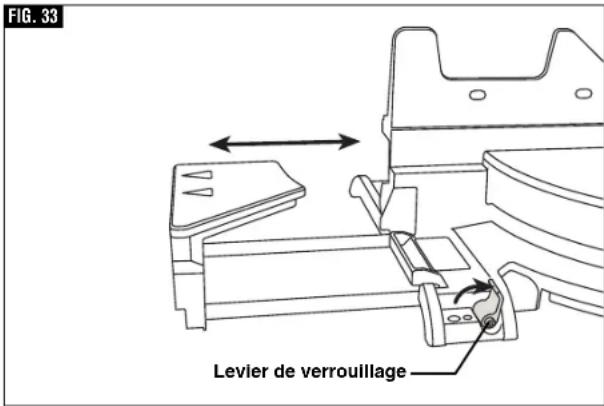
text_image
FIG. 33 Levier de verrouillage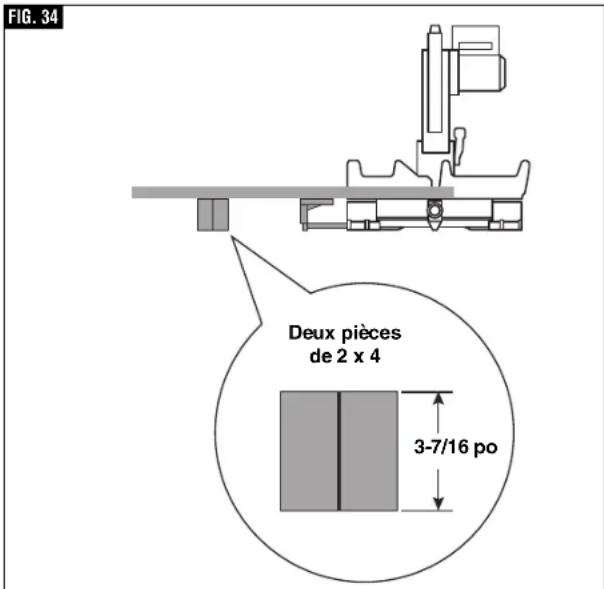
text_image
FIG. 34 Deux pièces de 2 x 4 3-7/16 poAVERTISSEMENT
text_image
FIG. 49 5" 5-1/2" 2-3/4" 2" 1-1/2" 17-1/4" 2-1/2" 6" 1-1/2" 2" 2-3/4"natural_image
Simple line drawing of a faucet with a handle and base (no text or symbols)
text_image
Operating/Safety Instructions © BOSCH
Bolsa para polvo
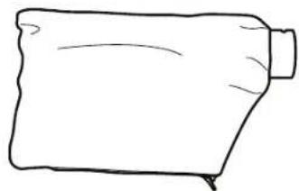
natural_image
Simple line drawing of a cylindrical object with a protruding shaft (no text or symbols)
natural_image
Diagram of a mechanical clamp or bracket with no visible text or symbolsDestornillador Phillips No. 2 r
Casquillo de 5 mm (suministrado)

Llave hexagonal de 4 mm
natural_image
Technical line drawing of a mechanical assembly with no visible text or symbolsnatural_image
Technical line drawing of a mechanical assembly with no visible text or symbolsnatural_image
Silhouette of a human figure holding a small mechanical device, labeled 'FIG. 22' (no text or symbols on the diagram itself)▼ LEVANTE LA SIERRA POR LOS MANGOS DE TRANSPORTE FUNDIDOS CON LA PIEZA
natural_image
Technical line drawing of a mechanical device with wheels and mounting brackets (no text or symbols)text_image
FIG. 27 CORRECTO USO INCORRECTOnatural_image
Mechanical assembly diagram showing two configurations with a crosshair and checkmark (no text or symbols)FIG. 33
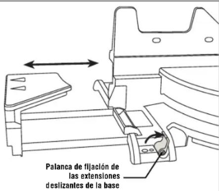
text_image
Two 2x4 Pieces 3-7/16"text_image
FIG. 49 5" 4" 5-1/2" 6" 2-3/4" 2-1/2" 2-3/4" 2" 1-1/2" 1-1/2" 2" 17-1/4"Robert Bosch Tool Corporation ("Seller") warrants to the original purchaser only, that all BOSCH portable and benchtop power tools will be free from defects in material or workmanship for a period of one year from date of purchase. SELLER'S SOLE OBLIGATION AND YOUR EXCLUSIVE REMEDY under this Limited Warranty and, to the extent permitted by law, any warranty or condition implied by law, shall be the repair or replacement of parts, without charge, which are defective in material or workmanship and which have not been misused, carelessly handled, or misrepaired by persons other than Seller or Authorized Service Station. To make a claim under this Limited Warranty, you must return the complete portable or benchtop power tool product, transportation prepaid, to any BOSCH Factory Service Center or Authorized Service Station. For Authorized BOSCH Power Tool Service Stations, please refer to your phone directory.
THIS LIMITED WARRANTY DOES NOT APPLY TO ACCESSORY ITEMS SUCH AS CIRCULAR SAW BLADES, DRILL BITS, ROUTER BITS, JIGSAW BLADES, SANDING BELTS, GRINDING WHEELS AND OTHER RELATED ITEMS.
ANY IMPLIED WARRANTIES SHALL BE LIMITED IN DURATION TO ONE YEAR FROM DATE OF PURCHASE. SOME STATES IN THE U.S., SOME CANADIAN PROVINCES DO NOT ALLOW LIMITATIONS ON HOW LONG AN IMPLIED WARRANTY LASTS, SO THE ABOVE LIMITATION MAY NOT APPLY TO YOU.
IN NO EVENT SHALL SELLER BE LIABLE FOR ANY INCIDENTAL OR CONSEQUENTIAL DAMAGES (INCLUDING BUT NOT LIMITED TO LIABILITY FOR LOSS OF PROFITS) ARISING FROM THE SALE OR USE OF THIS PRODUCT. SOME STATES IN THE U.S. AND SOME CANADIAN PROVINCES DO NOT ALLOW THE EXCLUSION OR LIMITATION OF INCIDENTAL OR CONSEQUENTIAL DAMAGES, SO THE ABOVE LIMITATION OR EXCLUSION MAY NOT APPLY TO YOU.
THIS LIMITED WARRANTY GIVES YOU SPECIFIC LEGAL RIGHTS, AND YOU MAY ALSO HAVE OTHER RIGHTS WHICH VARY FROM STATE TO STATE IN THE U.S., PROVINCE TO PROVINCE IN CANADA AND FROM COUNTRY TO COUNTRY.
THIS LIMITED WARRANTY APPLIES ONLY TO PORTABLE AND BENCHTOP ELECTRIC TOOLS SOLD WITHIN THE UNITED STATES OF AMERICA, CANADA AND THE COMMONWEALTH OF PUERTO RICO. FOR WARRANTY COVERAGE WITHIN OTHER COUNTRIES, CONTACT YOUR LOCAL BOSCH DEALER OR IMPORTER.
GARANTIE LIMITÉE DES OUTILS ÉLECTRIQUES PORTATIFS ET D'ÉTABLI BOSCH
© Robert Bosch Tool Corporation 1800 W. Central Road Mt. Prospect, IL 60056-2230
Exportado por: Robert Bosch Tool Corporation Mt. Prospect, IL 60056-2230, E.U.A.