GCD18V-14 Professional - Saw BOSCH - Free user manual and instructions
Find the device manual for free GCD18V-14 Professional BOSCH in PDF.

User questions about GCD18V-14 Professional BOSCH
0 question about this device. Answer the ones you know or ask your own.
Ask a new question about this device
Download the instructions for your Saw in PDF format for free! Find your manual GCD18V-14 Professional - BOSCH and take your electronic device back in hand. On this page are published all the documents necessary for the use of your device. GCD18V-14 Professional by BOSCH.
USER MANUAL GCD18V-14 Professional BOSCH
IMPORTANT Read Before Using
IMPORTANT Lire avant usage
IMPORTANTE Leer antes de usar

natural_image
Icon of a person reading a book inside a circle (no text or symbols)Operating / Safety Instructions Consignes d'utilisation / de sécurité Instrucciones de funcionamiento y seguridad
GCD18V-14
natural_image
3D rendering of a mechanical cutting tool with visible blades and base plate (no text or symbols)
BOSCH
Call Toll Free for Consumer Information & Service Locations Pour obtenir des informations et les adresses de nos centres de service après-vente, appelez ce numéro gratuit Llame gratis para obtener información para el consumidor y ubicaciones de servicio
1-877-BOSCH99 (1-877-267-2499) www.boschtools.com
For English Version See page 2
| Safety SymbolsThe definitions below describe the level of severity for each signal word.Please read the manual and pay attention to these symbols. | |
 | This is the safety alert symbol. It is used to alert you to potential personal injury hazards. Obey all safety messages that follow this symbol to avoid possible injury or death. |
 | DANGER indicates a hazardous situation which, if not avoided, will result in death or serious injury. |
 | WARNING indicates a hazardous situation which, if not avoided, could result in death or serious injury. |
 | CAUTION indicates a hazardous situation which, if not avoided, could result in minor or moderate injury. |
Table of Contents
General Power Tool Safety Warnings ..... 3
Safety Warnings for Dry Cut Saws ..... 5
Additional Safety Warnings 6
Disposal. 6
Intended Use 7
Symbols 8
Getting to Know Your GCD18V-14 Dry Cut Saw 9
Specifications 11
Recommended Cutting Capacities ..... 11
Unpacking and Checking Contents ..... 12
Unpacking the Dry Cut Saw .... 12
Checking Contents in Package ..... 12
Assembly 13
Inserting and Releasing the Battery Pack ... 13
Removing and Installing the Blade ..... 13
Adjustments.... 15
Using the Head Assembly Lock Pin..... 15
Adjusting the Vise Stop 15
Transporting and Mounting 19
Preparing to Lift the Saw 19
Transporting the Saw 19
Mounting Applications ..... 19
Basic Saw Operations 21
Switch Activation 21
Brake Operation.... 21
Laser Line Guide 21
Overload Indicator 23
Body and Hand Position.... 23
Workpiece Support 24
Tips for Using the Dry Cut Saw 28
Making a Cut 28
Emptying the Chip Collector 30
Maintenance and Lubrication 31
Service.... 31
Batteries 31
Cleaning 31
Care of Blades 31
Tool Lubrication 31
Bearings.... 31
Troubleshooting 32
Troubleshooting Guide - Electrical ..... 32
Troubleshooting Guide - General ..... 32
General Power Tool Safety Warnings
WARNING
Read all safety warnings, instructions, illustrations and specifications provided with this power tool. Failure to follow all instructions listed below may result in and/or serious injury.
SAVE ALL WARNINGS AND INSTRUCTIONS FOR FUTURE REFERENCE.
The term “power tool” in the warnings refers to your mains-operated (corded) power tool or battery operated (cordless) power tool.
1. Work area safety
a. Keep work area clean and well lit. Cluttered or dark areas invite accidents.
b. Do not operate power tools in explosive atmospheres, such as in the presence of flammable liquids, gases or dust. Power tools create sparks which may ignite the dust or fumes.
c. Keep children and bystanders away while operating a power tool. Distractions can cause you to lose control.
2. Electrical safety
a. Power tool plugs must match the outlet. Never modify the plug in any way. Do not use any adapter plugs with earthed (grounded) power tools. Unmodified plugs and matching outlets will reduce risk of electric shock.
b. Avoid body contact with earthed or grounded surfaces, such as pipes, radiators, ranges and refrigerators. There is an increased risk of electric shock if your body is earthed or grounded.
c. Do not expose power tools to rain or wet conditions. Water entering a power tool will increase the risk of electric shock.
d. Do not abuse the cord. Never use the cord for carrying, pulling or unplugging the power tool. Keep cord away from heat, oil, sharp edges or moving parts. Damaged or entangled cords increase the risk of electric shock.
e. When operating a power tool outdoors, use an extension cord suitable for outdoor use.
Use of a cord suitable for outdoor use reduces the risk of electric shock.
f. If operating a power tool in a damp location is unavoidable, use a Ground Fault Circuit Interrupter (GFCI) protected supply. Use of a GFCI reduces the risk of electric shock.
3. Personal safety
a. Stay alert, watch what you are doing and use common sense when operating a power tool.
Do not use a power tool while you are tired or under the influence of drugs, alcohol or medication. A moment of inattention while operating power tools may result in serious personal injury.
b. Use personal protective equipment. Always wear eye protection. Protective equipment such as a dust mask, non-skid safety shoes, hard hat or hearing protection used for appropriate conditions will reduce personal injuries.
c. Prevent unintentional starting. Ensure the switch is in the off-position before connecting to power source and/or battery pack, picking up or carrying the tool. Carrying power tools with your finger on the switch or energizing power tools that have the switch on invites accidents.
d. Remove any adjusting key or wrench before turning the power tool on. A wrench or a key left attached to a rotating part of the power tool may result in personal injury.
e. Do not overreach. Keep proper footing and balance at all times. This enables better control of the power tool in unexpected situations.
f. Dress properly. Do not wear loose clothing or jewelry. Keep your hair and clothing away from moving parts. Loose clothes, jewelry or long hair can be caught in moving parts.
g. If devices are provided for the connection of dust extraction and collection facilities, ensure these are connected and properly used. Use of dust collection can reduce dust-related hazards.
h. Do not let familiarity gained from frequent use of tools allow you to become complacent and ignore tool safety principles. A careless action can cause severe injury within a fraction of a second.
4. Power tool use and care
a. Do not force the power tool. Use the correct power tool for your application. The correct
General Power Tool Safety Warnings
power tool will do the job better and safer at the rate for which it was designed.
b. Do not use the power tool if the switch does not turn it on and off. Any power tool that cannot be controlled with the switch is dangerous and must be repaired.
c. Disconnect the plug from the power source and/or remove the battery pack, if detachable, from the power tool before making any adjustments, changing accessories, or storing power tools. Such preventive safety measures reduce the risk of starting the power tool accidentally.
d. Store idle power tools out of the reach of children and do not allow persons unfamiliar with the power tool or these instructions to operate the power tool. Power tools are dangerous in the hands of untrained users.
e. Maintain power tools and accessories. Check for misalignment or binding of moving parts, breakage of parts and any other condition that may affect the power tool's operation. If damaged, have the power tool repaired before use. Many accidents are caused by poorly maintained power tools.
f. Keep cutting tools sharp and clean. Properly maintained cutting tools with sharp cutting edges are less likely to bind and are easier to control.
g. Use the power tool, accessories and tool bits etc. in accordance with these instructions, taking into account the working conditions and the work to be performed. Use of the power tool for operations different from those intended could result in a hazardous situation.
h. Keep handles and grasping surfaces dry, clean and free from oil and grease. Slippery handles and grasping surfaces do not allow for safe handling and control of the tool in unexpected situations.
5. Battery tool use and care
a. Recharge only with the charger specified by the manufacturer. A charger that is suitable for one type of battery pack may create a risk of fire when used with another battery pack.
b. Use power tools only with specifically designated battery packs. Use of any other battery packs may create a risk of injury and fire.
c. When battery pack is not in use, keep it away from other metal objects, like paper clips,
coins, keys, nails, screws or other small metal objects, that can make a connection from one terminal to another. Shorting the battery terminals together may cause burns or a fire.
d. Under abusive conditions, liquid may be ejected from the battery; avoid contact. If contact accidentally occurs, flush with water. If liquid contacts eyes, additionally seek medical help. Liquid ejected from the battery may cause irritation or burns.
e. Do not use a battery pack or tool that is damaged or modified. Damaged or modified batteries may exhibit unpredictable behavior resulting in fire, explosion or risk of injury.
f. Do not expose a battery pack or tool to fire or excessive temperature. Exposure to fire or temperature above 265^ F ( 130^ C) may cause explosion.
g. Follow all charging instructions and do not charge the battery pack or tool outside the temperature range specified in the instructions. Charging improperly or at temperatures outside the specified range may damage the battery and increase the risk of fire.
6. Service
a. Have your power tool serviced by a qualified repair person using only identical replacement parts. This will ensure that the safety of the power tool is maintained.
b. Never service damaged battery packs. Service of battery packs should only be performed by the manufacturer or authorized service providers.
Safety Warnings for Dry Cut Saws
Dry Cut saws are intended for the cutting of various profiles of ferrous and non-ferrous materials using appropriate carbide tipped circular saw blades, they cannot be used with abrasive cut-off wheels. Abrasive dust causes moving parts such as the lower guard to jam.
The rated speed of the carbide tipped saw blade must be at least equal to the maximum speed marked on the dry cut saw tool. Accessories running faster than their rated speed can break and fly apart.
Do not use blades that require liquid coolants. Using water or other liquid coolants may result in electrocution or shock.
Keep bystanders a safe distance away from work area. Anyone entering the work area must wear personal protective equipment. Fragments of workpiece or metal swarf may fly away and cause injury beyond immediate area of operation.
Do not operate the dry cut saw near flammable materials. Do not operate the dry cut saw while placed on a combustible surface such as wood. Sparks could ignite these materials.
WARNING
Never cut magnesium with this tool.
Never support the workpiece by hand. Do not feed the workpiece into the blade or cut "free hand" in any way. The workpiece must be stationary and clamped against the vise stop, vise clamp, and the table. Do not use this saw to cut pieces that are too small to be securely clamped. Unrestrained or moving workpieces could be thrown at high speeds, causing injury. If you use your hand to support the workpiece, there is a risk of injury from blade contact.
All adjusting locking levers must be tight and secure before making the cut. If blade adjustment shifts while cutting, it may cause binding and kick-back.
Do not reach behind the vise stop with either hand from either side of the saw blade, to remove metal scraps, or for any other reason while the blade is spinning. The proximity of the spinning saw blade to your hand may not be obvious and you may be seriously injured.
Inspect your workpiece before cutting. If the workpiece is bowed or warped, clamp it with the outside bowed face toward the vise stop. Always make certain that there is no gap between the workpiece, vise stop and table along the line of the cut. Bent or warped workpieces can twist or shift and may cause binding on the spinning saw blade while cutting.
Do not use the saw until the table is clear of all tools, metal scraps, etc., except for the workpiece. Small debris or loose pieces of metal or other objects that contact the revolving blade can be thrown with high speed.
Ensure the dry cut saw is mounted or placed on a level, firm, and non-combustible work surface before use. A level and firm work surface reduces the risk of the dry cut saw becoming unstable.
Plan your work. Every time you change the miter angle setting, make sure the adjustable vise stop is set correctly to support the workpiece and will not interfere with the blade. Without turning the tool "ON" and with no workpiece on the table, move the saw blade through a complete simulated cut to assure there will be no interference or danger of cutting the fence.
Provide adequate support such as table extensions, sawhorses, etc. for a workpiece that is longer than the tabletop. Workpieces wider than the dry cut saw table can tip if not securely supported. If the cut-off piece or workpiece tips, it can lift the lower guard or be thrown by the spinning blade.
Do not use another person as a substitute for a table extension or as additional support. Unstable support for the workpiece can cause the blade to bind or the workpiece to shift during the cutting operation pulling you and the helper into the spinning blade.
The cut-off piece must not be jammed or pressed by any means against the spinning saw blade. If confined, i.e. using length stops, the cut-off piece could get wedged against the blade and thrown violently.
ALWAYS USE THE VISE OR SPECIAL FIXTURE TO CLAMP WORK SECURELY. Other aids such spring, bar, or C-clamps may be appropriate for certain sizes and shapes of workpiece. Use care in selecting and placing these clamps to avoid interference with the guard and blade. Make a dry run before making a cut.
Always use a clamp or a fixture designed to properly support round material such as rods or tubing. Rods and tubing have a tendency to roll while being cut, causing the blade to "bite" and pull the work into the blade.
Let the blade reach full speed before contacting the workpiece. This will reduce the risk of the workpiece being thrown.
Safety Warnings for Dry Cut Saws
If the workpiece or blade becomes jammed, turn the dry cut saw off. Wait for all moving parts to stop and remove the battery pack. Then work is free the jammed material. Continued sawing with a jammed workpiece could cause loss of control or damage to the dry cut saw. Investigate and take corrective actions to eliminate the cause of blade binding.
When restarting a saw in the workpiece, center the saw blade in the kerf so that the saw teeth are not engaged into the material. If a saw blade binds, it may walk up or kickback from the workpiece as the saw is restarted.
After finishing the cut, release the switch, hold the saw head down and wait for the blade to stop
before removing the cut-off piece. Reaching with your hand near the coasting blade is dangerous.
Hold the handle firmly when making an incomplete cut or when releasing the switch before the saw head is completely in the down position. The braking action of the saw may cause the saw head to be suddenly pulled downward, causing a risk of injury.
Avoid overheating the saw blade tips.
Regularly clean the power tool's air vents. The motor's fan can draw the dust inside the housing and excessive accumulation of powdered metal may cause electrical hazards.
Additional Safety Warnings
GFCI and personal protection devices like electrician's rubber gloves and footwear will further enhance your personal safety.
Develop a periodic maintenance schedule for your tool. When cleaning a tool be careful not to disassemble any portion of the tool since internal wires may be misplaced or pinched or safety guard return springs may be improperly mounted.
Certain cleaning agents such as gasoline, carbon tetrachloride, ammonia, etc. may damage plastic parts.
WARNING
Some dust created by power sanding, sawing, grinding,
drilling, and other construction activities contains chemicals known to cause cancer, birth defects or other reproductive harm. Some examples of these chemicals are:
- Lead from lead-based paints,
- Crystalline silica from bricks and cement and other masonry products, and
- Arsenic and chromium from chemically-treated lumber.

Before each use, review all warnings located on the dry

text_image
WARNING Wear Eye ProtectionThe operation of any power tool can result in foreign objects being thrown into the eyes, which can result in severe eye damage. Always wear safety goggles that comply with ANSI Z87.1 (shown on pack-
age) before commencing power tool operation.
Disposal
This section is part of Robert Bosch Tool Corporation's commitment to preserving our environment and conserving our natural resources.
Tool Disposal
Do not dispose of power tools and batteries/re-chargeable batteries into household waste!
Your risk from these exposures varies, depending on how often you do this type of work. To reduce your exposure to these chemicals: work in a well ventilated area, and work with approved safety equipment, such as those dust masks that are specially designed to filter out microscopic particles.
WARNING
Do not use the dry cut saw to cut fiber cement board. Cut-
ting materials containing crystalline silica may create exposures to respirable silica dust.
gBattery Disposal
Do not attempt to disassemble the battery or remove any components projecting from the battery terminals. Fire or injury may result. Prior to disposal, protect exposed terminals with heavy insulating tape to prevent shorting.
SAVE THESE INSTRUCTIONS
Additional Safety Rules
Lithium-Ion Batteries

If equipped with a lithium-ion battery, the battery must be collected, recycled, or disposed of in an environmentally sound manner.
The EPA certified RBRC Battery Recycling Seal on the lithium-ion (Li-ion)
battery indicates Robert Bosch Tool Corporation is voluntarily participating in an industry program to collect and recycle these batteries at the end their useful life, when taken out of service in the
United States or Canada. The RBRC program provides a convenient alternative to placing used Li-ion batteries into the trash or the municipal waste stream, which may be illegal in your area.
Please call 1-800-8-BATTERY for information on Li-ion battery recycling and disposal bans/restrictions in your area or return your batteries to a Bosch/Dremel Service Center for recycling. Robert Bosch Tool Corporation's involvement in this program is part of our commitment to preserving our environment and conserving our natural resources.
Intended Use
WARNING
Use this dry cut saw only as intended. Unintended use may injury and property damage.
This dry cut saw is intended for the cutting of various profiles of ferrous and non-ferrous materials. It is designed only for use with 14-inch (355 mm) carbide tipped circular saw blades rated 1300/min (RPM) or greater and intended for cutting metal. This dry cut saw is also intended for cutting only banded drywall metal stud bundles.
WARNING
Cut only full and banded bundles of drywall steel studs
with this dry cut saw. Unbanded steel stud bundles, or bundles of any other material profile, such as rebar, may not clamp properly. Cutting improperly clamped workpieces may result in workpiece instability, kickback, tool damage, and serious personal injury.
WARNING
Never cut magnesium with this tool.
WARNING
Do not use abrasive wheels. This tool is not intended for
use with any type of abrasive cut-off wheels.
WARNING
Do not cut masonry or cement materials with this dry cut
'saw. The dust from cutting masonry or concrete materials will cause the lower guard to become sluggish and may not close fully and quickly after cutting these materials.
WARNING
Do not use wet or dry Diamond cutting wheels, or water feed dry cut saw. Masonry cutting the lower guard system, hardened to become inoperable. Use of cutting applications with an elec- l cause electric shock hazards.
SAVE THESE INSTRUCTIONS
Symbols
IMPORTANT: Some of the following symbols may be used on your tool. Please study them and learn their meaning. Proper interpretation of these symbols will allow you to operate the tool better and safer.
| Symbol Designation/Explanation | |
| V Volts (voltage) | |
| A Amperes (current) | |
| Hz Hertz (frequency, cycles per second) | |
| W Watt (power) | |
| kg Kilograms (weight) | |
| min Minutes (time) | |
| s Seconds (time) | |
| ∅ Diameter (size of drill bits, grinding wheels, etc.) | |
| n_0 | No load speed (rotational speed, at no load) |
| n Rated speed (Maximum attainable speed) | |
| .../min | Revolutions or reciprocation per minute (revolutions, strokes, surface speed, orbits etc. per minute) |
| 0 Off position (zero speed, zero torque...) | |
 | Arrow (action in the direction of arrow) |
| --- | Direct current (Type or a characteristic of current) |
 | Alerts user to read manual. |
 | Alerts user to wear eye protection. |
 | No hands zone. |
 | No carry area. |
 | Designates Li-ion battery recycling program. |
 | This symbol designates that this tool is listed by Underwriters Laboratories, to United States and Canadian Standards. |
 Intertek Intertek | This symbol designates that this tool is listed by the Intertek Testing Services, to United States and Canadian Standards. |
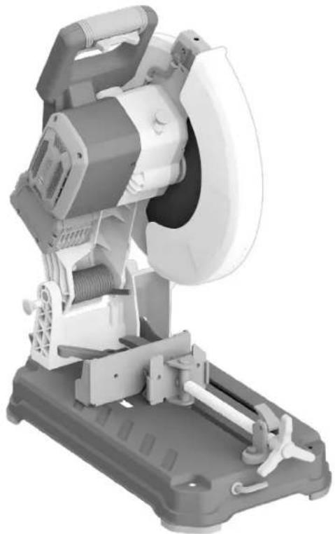
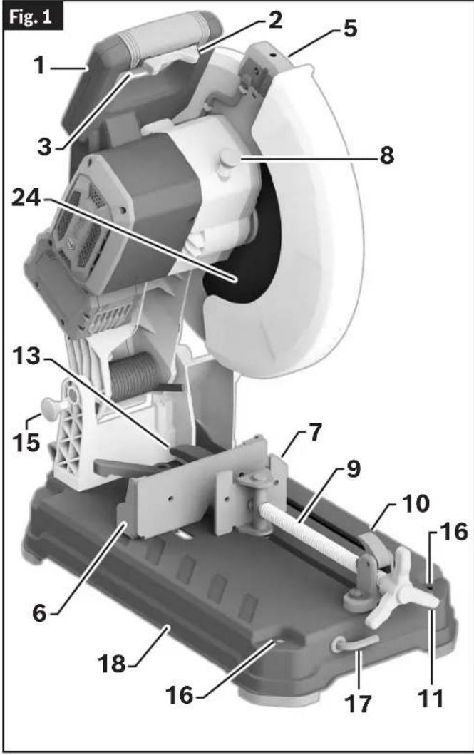
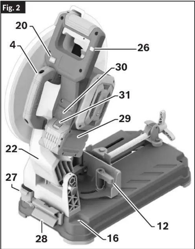
Getting to Know Your GCD18V-14 Dry Cut Saw
text_image
Fig. 1 1 2 3 5 8 24 13 15 7 9 10 16 6 18 16 17 111 Main Handle - Contains the Power Switch. Pulling this handle down lowers the Blade into the workpiece.
2 Switch Lock-OFF Toggle - Locks the Power Switch in the OFF position. It needs to be moved left or right before the Power Switch can be pressed.
3 Power Switch - Used with the Switch Lock-OFF Toggle, energizes the unit.
4 Carry Handle - Is used to transport the saw.
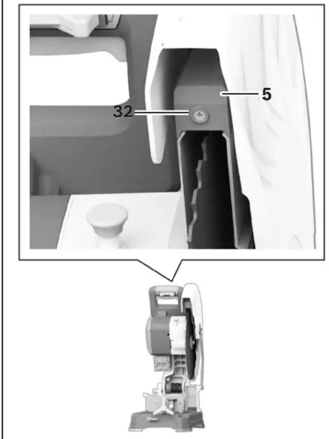
5 Laser Protection Cap - Protects the optical lens from damage.
6 Vise Stop - Swivels 0^ to 45^ to allow for angled miter cuts.
7 Vise Clamp - Securely holds the workpiece to the Vise Stop.
8 Spindle Lock - Locks Spindle and prevents rotation during Blade removal and installation.
9 Locking Spindle
text_image
Fig. 2 20 4 26 30 31 29 22 27 12 16 28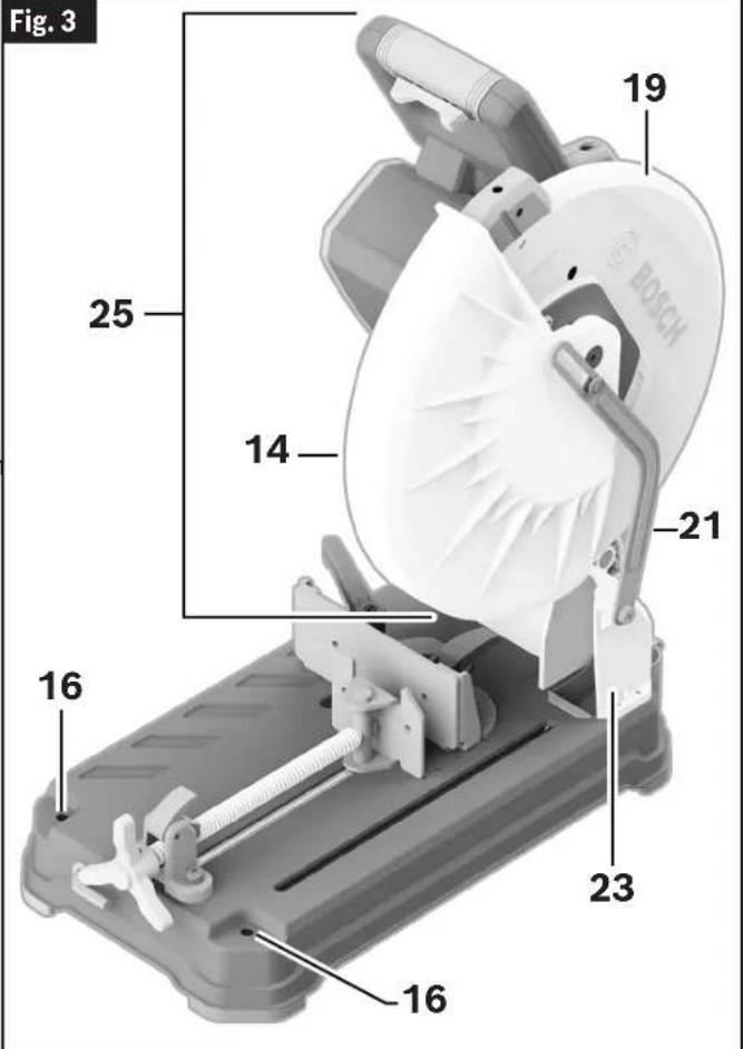
text_image
Fig. 3 19 25 14 21 16 23 16 16Getting to Know Your GCD18V-14 Dry Cut Saw
Fig. 4
text_image
32 515 Head Assembly Lock Pin - Used to lock the tool's Head Assembly in the lower position for transporting.
16 Mounting Holes – Provides the ability to mount the Dry Cut Saw to a workbench.
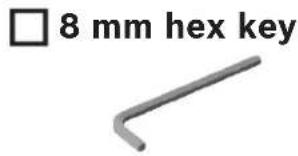
17 Hex Key (8 mm) - This is utilized for removal and installation of the Blade. The Hex Key is conveniently stored on the front of your Dry Cut Saw.
18 Base - Provides working surface to support workpiece.
19 Upper Guard - Covers upper portion of the Blade.
20 Laser On/Off Switch – Allows for activation of the cutting line indicator of the saw blade.
21 Lower Guard Linkage - Allows for smooth movement of the Lower Guard.
22 Tool Arm
23 Chip Deflector - deflects metal chips and other debris generated during cutting into the Chip Collector.
24 Blade - Use only 14" (355 mm) diameter blades with 1" (25.4 mm) diameter arbor holes.
25 Head Assembly
26 Overload Indicator – Provides feedback of the current load conditions of the Dry Cut Saw.
27 Chip Collector - A removable box where metal chips and debris from the cutting process are collected.
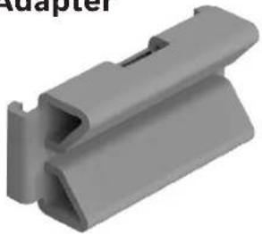
28 K-Adapter - A clamping fixture for cutting of round material from 2" (50.8 mm) to a maximum of 4.5" (114.3 mm) in diameter.
29 Battery Pack (Sold separately.)
30 Battery Bay - Used to insert Bosch Battery or AMPSshare Battery packs.
31 Battery Pack Release Button – used to remove Battery Pack from the Battery Bay.
32 Set Screw for Laser Protection Cap – Used to remove the laser protection cap.
10 Quick Release Lock Lever - This is used to quickly release and engage the Vise Clamp.
11 Vise Clamp Handle – This is used to tighten or loosen the Vise Clamp.
12 Miter Adjustment Handle - This is used to adjust the Vise Stop 0^ to 45^ to allow for angled miter cuts.
13 Cam Handle – Is used to move the Vise Stop into the selected position.
14 Lower Blade Guard – The Lower Blade Guard helps protect your hands from the spinning Blade. It retracts as the Head Assembly is lowered into the workpiece.
Specifications
| Model number | GCD18V-14 |
| Voltage | 18V --- |
| No Load Speed | 1300/min (RPM) |
| Blade Diameter | 14" (355 mm) |
| Blade Thickness | .070" - .087" (1.8 - 2.2 mm) |
| Arbor | 1" (25.4 mm) |
| Permitted battery temperature during charging | 0...+45°C (+32...113°F) |
| Permitted battery temperature during operation and storage | -20...+50°C (-4...122°F) |
| Permitted ambient temperature during charging | 0...+35°C (+32...+95°F) |
Recommended Cutting Capacities
WARNING
Use of this tool beyond recommended cutting capacities may lead to motor burn-out.
| Workpiece Shape | Material/Miter Angle Maximum Height Maximum Width | ||
 | Round material at 0° 5" (127 mm) | 5" (127 mm) | |
| Round material at 45° 4-1/2" (115 mm) | 4-1/2" (115 mm) | ||
 | Rectangle material at 0° 4" (101 mm) | 5" (127 mm) | |
| Rectangle material at 45° 4-1/2" (115 mm) | 4-1/2" (115 mm) | ||
 | Square material at 0° 5" (127 mm) | 5" (127 mm) | |
| Square material at 45° 4-1/2" (115 mm) | 4-1/2" (115 mm) | ||
 | L-Profile material at 0° 3-1/8" (80 mm) | 3-1/8" (80 mm) | |
| L-Profile material at 45° | 3-1/8" (80 mm) | 3-1/8" (80 mm) | |
 | U-Channel material at 0° | 5" (127 mm) | 5" (127 mm) |
| U-Channel material at 45° | 4-1/2" (115 mm) | 4-1/2" (115 mm) | |
 | Banded steel stud bundle* at 0° | 4" (101 mm) | 7-5/8" (194 mm) |
* Only cut 20 or 25 gauge steel studs banded in bundles of ten.
Unpacking and Checking Contents
Unpacking the Dry Cut Saw

Never carry the tool by the Main Handle.

If any parts are missing, do not install the battery or turn
the switch on until the missing parts are obtained and are installed correctly.
The saw is shipped complete in one box.
When removing this tool from packaging materials, locate and reach down to the main carry handle and slowly lift until it clears the package.
Separate tool from packing materials and examine the tool.
Checking Contents in Package
(Fig. 5)
Open the top of the package and look for all the included parts. Refer to Fig. 5.
Fig. 5
Parts Check off for each part
text_image
□ 8 mm hex key□ K-Adapter
natural_image
Gray plastic component with a V-shaped groove and a slot, labeled 'Adapter' in the top left corner (no other text or symbols)Assembly
WARNING To avoid possible injury, disconnect battery pack before performing any assembly, adjustments or repairs.
Inserting and Releasing the Battery Pack
Inserting the Battery Pack
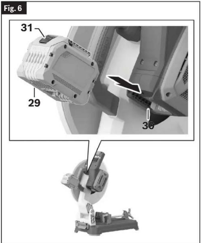
(Fig. 6)
Slide the charged Battery Pack 29 into the Battery Bay 30 until the Battery Pack 29 locks into position.
Your tool is equipped with a secondary locking latch to prevent the Battery Pack 29 from completely falling out of the Battery Bay 30, should it become loose due to vibration.
Releasing the Battery Pack
(Fig. 6)
To remove the Battery Pack 29, press the Battery Pack Release Button 31 and slide the Battery Pack 29 completely out of the Battery Bay 30.
text_image
Fig. 6 31 29 30Removing and Installing the Blade
CAUTION Always wear gloves when changing or handling blades.
Blade tips can cause personal injury.
Removing the Blade
(Fig. 1, Fig. 7, Fig. 8, Fig. 9, Fig. 10)
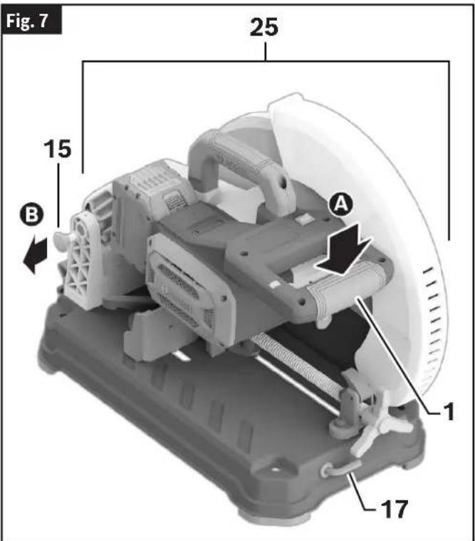
- Position the Saw Head Assembly 25 in the UP position. If in the DOWN position, press down slightly on the Saw Head Assembly 25A and pull out the Head Assembly Lock Pin 15B. Then allow the Saw Head Assembly 25 to come upC.
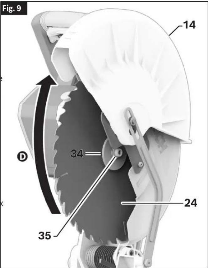
- Rotate Lower Blade Guard 14 up Dntil there is clear access to the Outer Washer 34 and Hex Bolt 35.
- Press and hold the Spindle Lock 8. Rotate the Blade 24 slowly until it fully seats into its locked position. Rotate the Hex Bolt 35 counterclockwise using the provided 8 mm Hex Key 17 to loosen the Blade 24.
- Remove the Hex Bolt 35 and Outer Washer 34. Carefully grab the Blade 24 and slide the Blade 24 completely off the Spindle Shaft 36.
text_image
Fig. 7 25 15 B A 1 17Assembly
Installing the 14" Blade
(Fig. 1, Fig. 7, Fig. 8, Fig. 9, Fig. 10)
WARNING To avoid injury, do not use blade larger or smaller than 14" (355 mm) diameter and 1" (25.4 mm) arbor. The blade's maximum plate thickness is 0.100" (2.54 mm).
WARNING To reduce risk of injury, use saw blade rated 1300/min (RPM) or greater.
- Follow all steps in "Removing the Blade" on page 13.
- Carefully handle the new Blade 24. Check that the rotation arrow on the Blade 24 matches the rotation arrow on the Upper Guard 19. With the Lower Blade Guard 14 up, carefully slide the new Blade 24 onto the Spindle Shaft 36. Move the Blade 24 so its arbor hole goes around the Support Ring 37 of the Inner Washer 38.
- Fit the Outer Washer 34 over the Spindle Shaft 36. Once fitted, finger-tighten the Hex Bolt 35 clockwise into the Spindle Shaft 36.
- Press and hold the Spindle Lock 8.
- Using the 8 mm Hex Key 17, rotate the Hex Bolt 35 clockwise until it fully seats into its lock position.
- Using the 8 mm Hex Key 17, tighten the Hex Bolt 35 clockwise. (ATTEN TION: DO NOT OVERTIGHTEN.)
-
Release the Spindle Lock 8 and Rotate the Lower Blade Guard 14 down.
-
Ensure the Blade 24 can rotate freely and does not make contact with the Lower Blade Guard 14 or the Upper Guard 19.
a9. Place the 8 mm Hex Key 17 back in the storage area.
After installing a new blade, lower the blade into the blade slot and check for any contact with the base structure. If the blade contacts the base, seek authorized service.
text_image
Fig. 9 14 34 24 35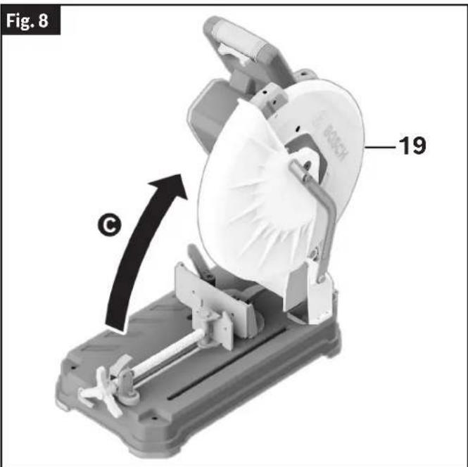
text_image
Fig. 8 19 ©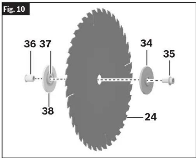
text_image
Fig. 10 36 37 38 34 35 24Adjustments
⚠ WARNING To avoid possible injury, disconnect battery pack before performing any assembly, adjustments or repairs.
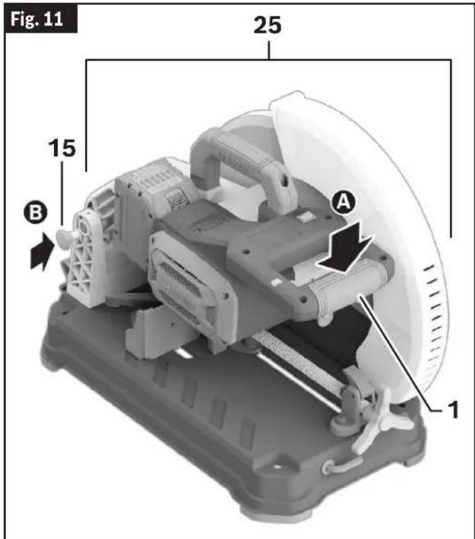
Using the Head Assembly Lock Pin
(Fig. 11)
The Head Assembly Lock Pin 15 is located on the left side of the tool near the Tool Arm 22. It is used to hold the tool's head assembly in the DOWN position. This position prevents the head from bouncing up and down during transportation. This also makes the tool more compact for lifting and storage.
To Engage the Head Assembly Lock Pin
(Fig. 11)
- Grasp the tool's Main Handle 1 and press down on the Head Assembly 25 A
- While pressing the tool head down, push in on the Head Assembly Lock Pin 15 B Release the Head Assembly 25. The Head Assembly 25 will be locked in the DOWN position.
text_image
Fig. 11 25 15 B A 1To Disengage the Head Assembly Lock Pin
(Fig. 7, Fig. 8)
- Grasp the Main Handle 1 and press down on the Head Assembly 25 A
- While pressing the head down, pull out the Head Assembly Lock Pin 15 ☐ While maintaining your grip on the Main Handle 1, release the Head Assembly Lock Pin 15. Slowly allow the spring-loaded Head Assembly 25 to come up to the top of its travel and then release the Main Handle 1.
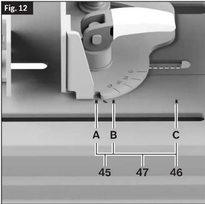
Adjusting the Vise Stop
(Fig. 12)
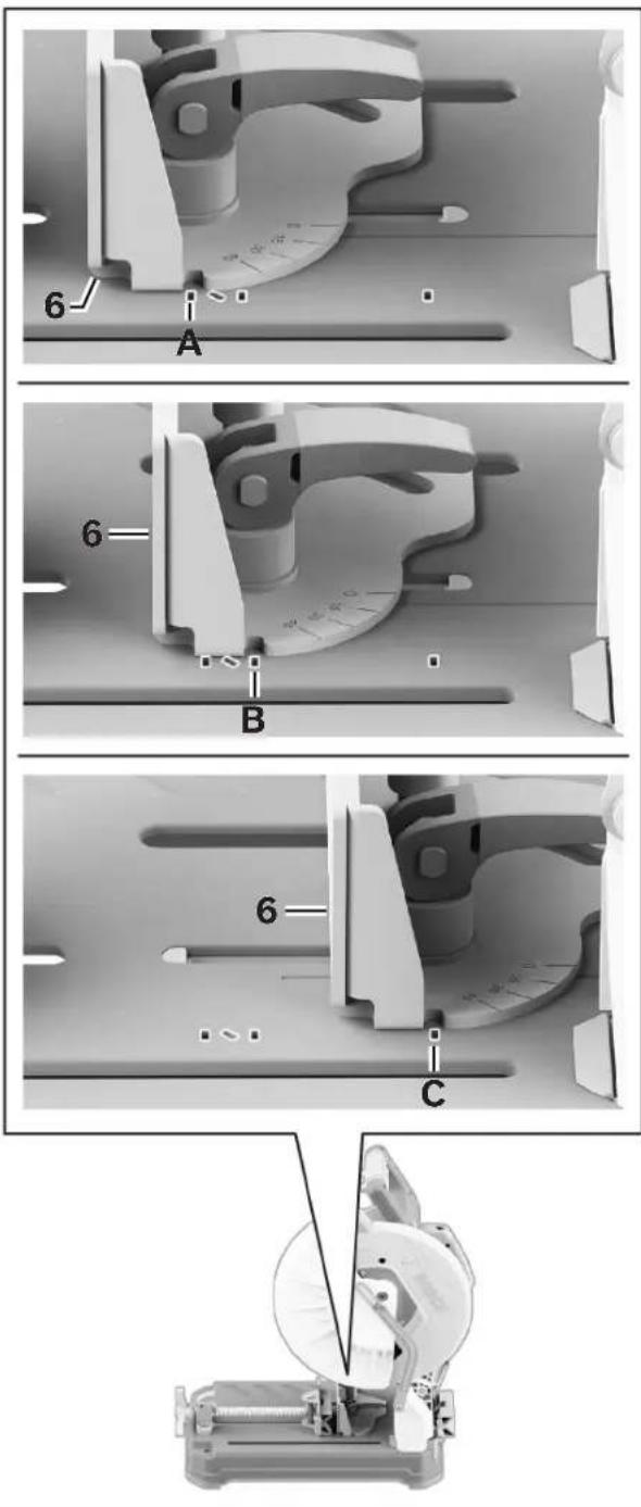
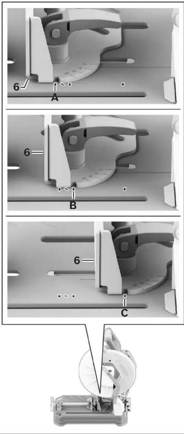
The Vise Stop 6 can be adjusted to accommodate cross or chop cuts in standard profiles and steel stud bundles at 90°. It can also be adjusted to perform miter cuts between 0° and 45° in standard profile sizes. In the 0° setting, two capacity settings are available: standard profile and steel stud bundle. Miter cuts can only be performed when the Vise Stop 6 is set in the Miter Zone 45.
The Base 18 is marked with slots next to the Vise Stop 6 that serve as an alignment guide. When the Vise Stop 6 is positioned between slot A and B it supports 90° chop cuts in standard profile sizes. When the Vise Stop 6 is aligned with slot C it supports 90° chop cuts in banded steel stud bundles (the Steel Stud Setting 46).
The space between slot A and slot B is called the Miter Zone 45. When the Vise Stop 6 is set in the miter zone it can be adjusted to make miter cuts of up to 45°. Do not perform miter cuts outside of the designated miter zone area (the No Miter Zone 47).
WARNING Do not set the Vise Stop for miter cuts outside of the miter
zone. Upstroke cutting may occur when Vise Clamp is set for miter cutting outside of the miter zone. Upstroke of the blade tends to pull the workpiece up from the vise and may result in serious damage to the tool and possible personal injury.
Adjustments
text_image
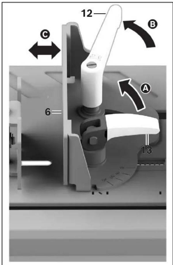
Fig. 12 A B C 45 47 46Adjusting the Vice Stop for Capacity
(Fig. 13, Fig. 14)
To increase cutting capacity at 0^ , make the following Vise Stop 6 adjustments:
- Move the Cam Handle 13 into the UP/UNLOCK position ☐ Unlock the Miter Adjustment Handle 12 by rotating it counterclockwise ☐. If more space for the Miter Adjustment Handle 12 is needed for unlocking, pull the Miter Adjustment Handle 12 up and rotate it clockwise until sufficient space for the Miter Adjustment Handle 12 has been obtained. Put the Miter Adjustment Handle 12 down in order to continue unlocking.
Note: The Miter Adjustment Handle 12 is spring loaded, so when pulled up, there will be tension present and when the Miter Adjustment Handle 12 is released, it will return to the down position.
-
Move the Vise Stop 6 forward or backward to the desired mounting location ©
-
Once the desired Vise Stop 6 position is selected, rotate the Miter Adjustment Handle 12 clockwise to tighten the Vise Stop 6.
Fig. 13
text_image
12 C 6 A B 13
natural_image
Mechanical tool with a circular component and attached bracket, no visible text or symbolsAdjustments
Fig. 14

Adjusting the Vice Stop for Miter Cutting
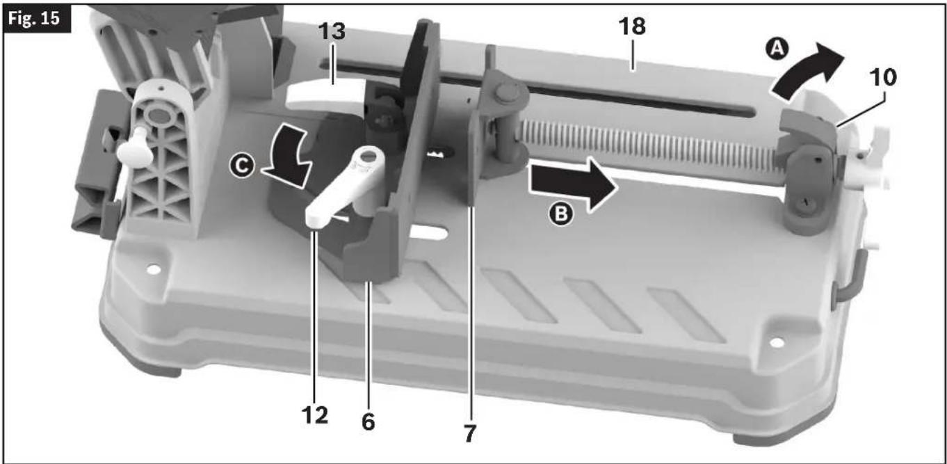
(Fig. 15, Fig. 16)
WARNING For miter cuts, do not set the Vise Stop outside of the miter
zone, as this may cause upstroke cutting. The upstroke of the blade tends to pull the workpiece up from the vise and may result in serious damage to the tool and possible personal injury.
For miter cutting from 0° to 45° left, the Vise Stop 6 should be positioned in the Miter Zone 45, from Slot A to Slot B.
To position the Vise Stop 6 for miter cutting, make the following adjustments:
- Set the Vise Stop 6 for the desired capacity, as described in "Adjusting the Vice Stop for Capacity" above.
- Lift the Quick Release Lock Lever 10 A, and pull the Vise Clamp 7 away from the Vise Stop 6 B
- Loosen the Miter Adjustment Handle 12 ©
-
Adjust the Vise Stop 6 to the desired angle by aligning the desired angle mark on the Miter Scale 39 with the Index Line 40 on the Base 18 D. The Vise Stop 6 can be adjusted between 0^ and 45^ . The Miter Scale 39 shows the angle of the Blade 24 relative to the angle of the Vise Stop 6.
-
Tighten the Miter Adjustment Handle 12.
Note: The Vise Stop 6 can be angled when the Cam Handle 13 is in the DOWN/LOCK position.
Adjustments
text_image
Fig. 15 13 18 A 10 C B 12 6 7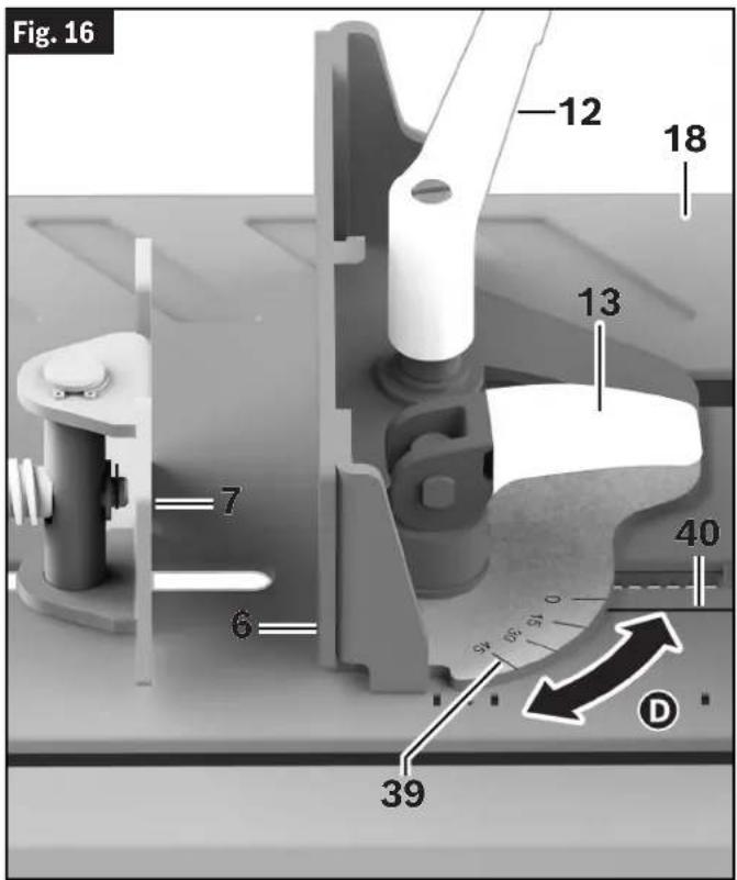
text_image
Fig. 16 12 18 13 7 40 6 59 59 D 39Transporting and Mounting
WARNING To avoid possible injury, disconnect battery pack before performing any assembly, adjustments or repairs.
WARNING To avoid injury, follow all statements identified below by the BULLET (•) symbol.
• To avoid back injury, hold the tool close to your body when lifting. Bend your knees so you can lift with your legs, not your back.
- Never lift tool by Main Switch Handle. This may cause serious damage to the tool.
- Place the saw on a firm, level surface where there is plenty of room for handling and properly supporting the workpiece.
• ONLY lift this saw by the Carry Handle.
Preparing to Lift the Saw
(Fig. 17)
- Push the tool's Head Assembly 25 down and lock in DOWN position using the Head Assem-Lock Pin 15 A.
- Push the Vise Clamp 7 all the way towards the Vise Stop 6 B. Engage the Quick Release Lock Lever 10, then tighten the Vise Clamp 7.
Note: When pushing the Vise Clamp 7 towards the Vise Stop 6, ensure the Vise Stop 6 is in the forward most position.
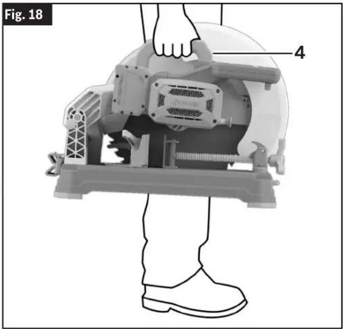
Transporting the Saw
(Fig. 17, Fig. 18)
Transport the tool by firmly gripping the Carry Handle 4. When transporting the tool, ensure the wheel side is directed toward your body.
text_image
Fig. 18 4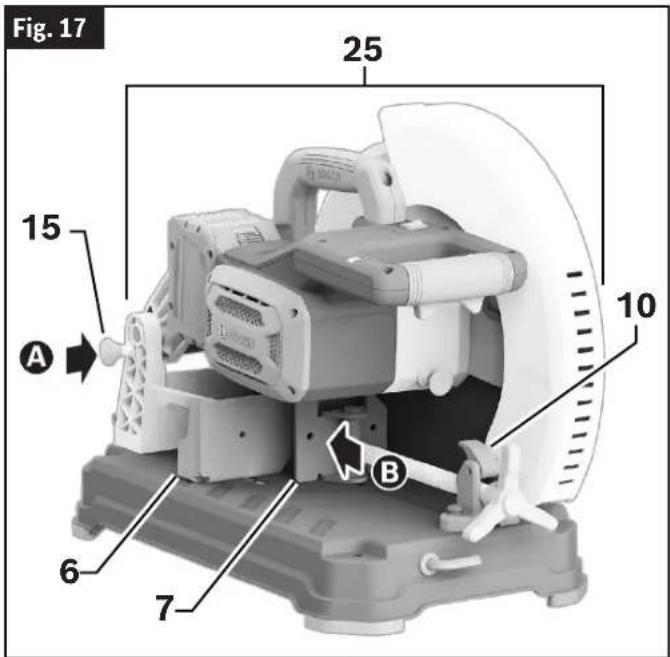
text_image
Fig. 17 25 10 15 A B 6 7Mounting Applications
WARNING Be certain the dry cut saw is mounted or placed on a level, firm work surface before using. A level and firm work surface reduces the risk of the dry cut saw becoming unstable.
Permanent Attachment to Workbench
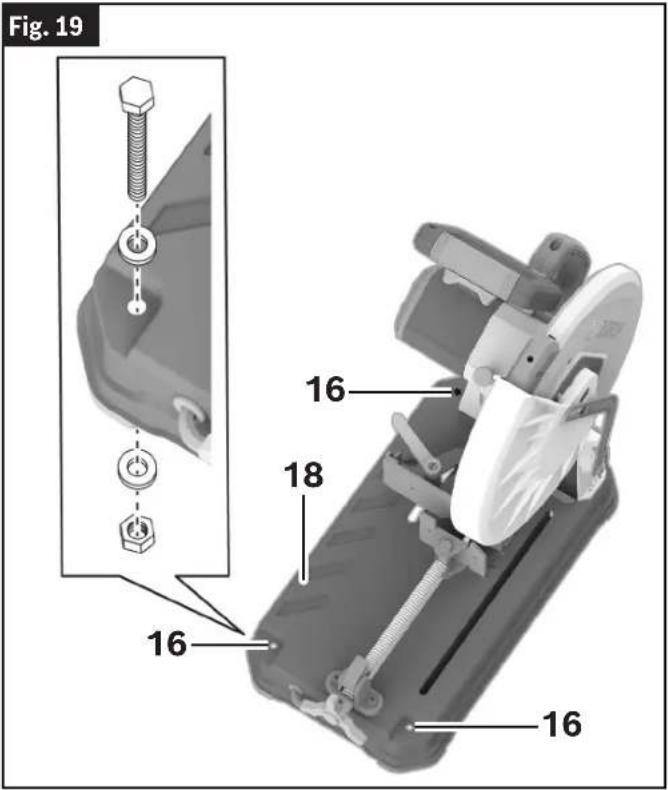
(Fig. 19)
- Each of the three Mounting Holes 16 should be bolted securely using 5/16" (M8) bolts, lock washers and hex nuts (not included).
- Locate and mark where the saw is to be mounted.
- Drill three 5/16" (8 mm) diameter holes through workbench.
- Place the dry cut saw on the workbench aligning the Mounting Holes 16 in the Base 18 with the holes drilled in the workbench. Install bolts, lock washers and hex nuts.
Transporting and Mounting
text_image
Fig. 19 16 16 18 16 16Temporary Mounting Using Clamps
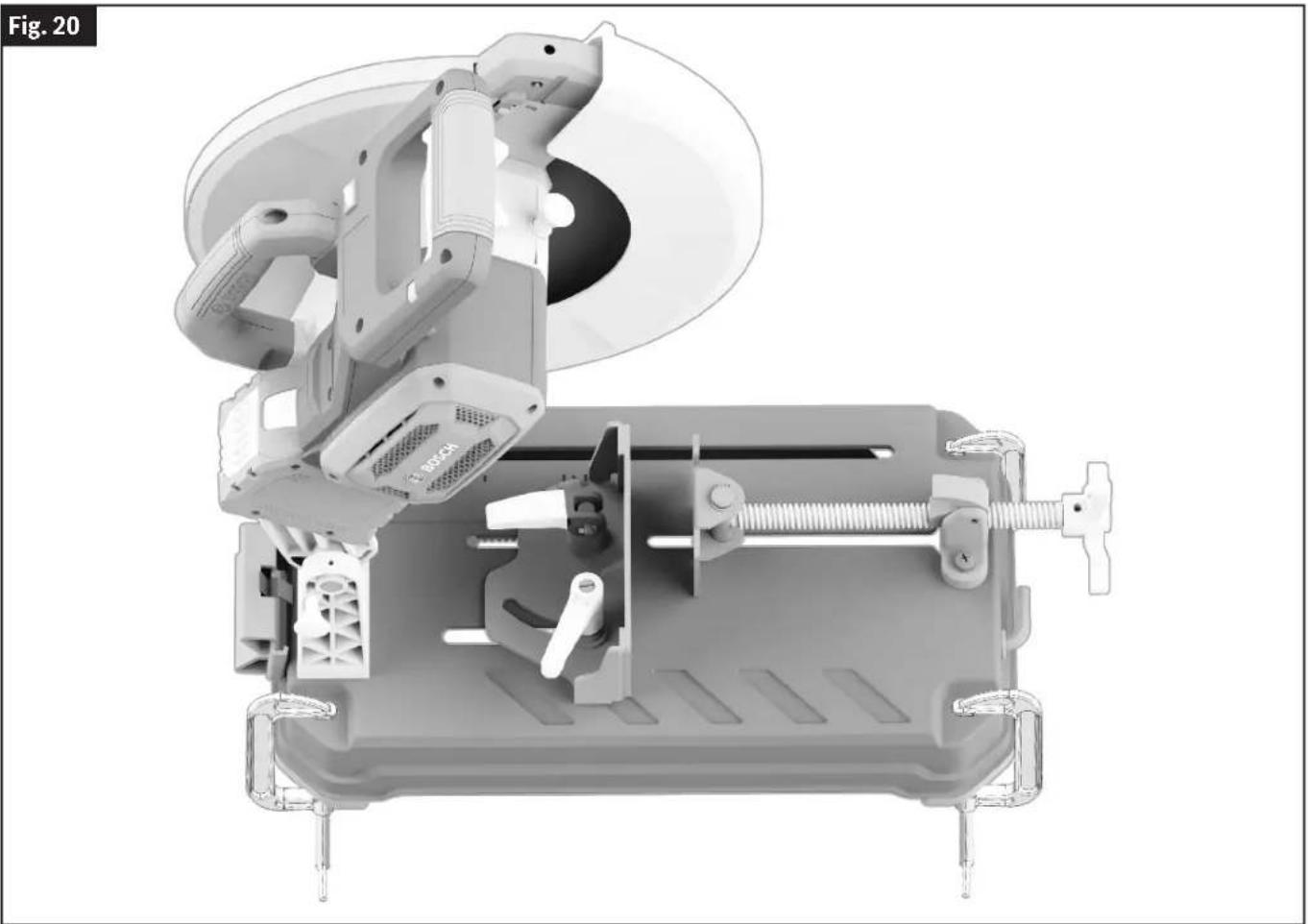
(Fig. 20)
- If necessary, clamp the dry cut saw to a workbench or table top.
- Place three or more clamps on the clamping areas and secure. There are clamping areas at three corners of the saw.
- Mounting with clamps may prevent access to some miter angles.
natural_image
3D mechanical assembly diagram showing internal components like a fan, housing, and clamping device (no text or symbols)Basic Saw Operations
WARNING To avoid possible injury, disconnect battery pack before performing any assembly, adjustments or repairs.
Switch Activation
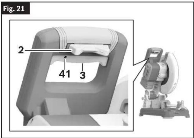
(Fig. 21)
For safety, the Power Switch 3 is designed to prevent accidental starts.
Note: The Power Switch 3 has a Padlock Provision 41 that can accommodate a padlock with a long shackle of up to 1/4" in diameter (not provided with the saw) to prevent unauthorized use.
To Turn the Tool On
Slide the Switch Lock-Off Toggle 2 with either thumb to disengage the lock. Then pull the Power Switch 3 and release the Switch Lock-Off Toggle 2.
To Turn the Tool Off
Release the Power Switch 3.
When the Power Switch 3 is released, the Switch Lock-Off Toggle 2 will lock the Power Switch 3 automatically, and the lever will no longer operate until the Switch Lock-Off Toggle 2 is engaged again.
text_image
Fig. 21 2 41 3Brake Operation
(Fig. 1)
WARNING The brake action of this saw is not intended as a safety feature. Re member to let the saw blade come to a complete stop be fore raising the blade from the workpiece. As always, the guard system is your best protection against unintentional contact with a spinning saw blade. NEVER wedge open or defeat the closing action of the lower guard.
WARNING Know the charge state of your bat tery. The electric braking action is initiated ONLY by the release of the power switch and in a tool that has power available. When electrical power is lost due to a discharged battery or other causes, the elec tric brake will not operate, and the motor will gradually slow down. Unexpected run-down time may cause property damage and/or personal injury.
Your saw is equipped with an automatic electric brake which is designed to stop the Blade 24 from spinning in about five (5) seconds after you release the Power Switch 3.
Braking starts once the power is turned off.
The brake requires a charged Battery Pack 29 to function. Stopping time will vary depending on, among other factors, saw Blade 24 used and number of actuations. The electric brake of your dry cut saw has been designed for a high degree of reliability, but unexpected circumstances such as contamination or failure of the motor's components can cause the brake to not activate. If the tool operates but the brake does not consistently stop the Blade 24 in about 5 seconds, DO NOT use the Dry Cut Saw and have it serviced by a Bosch Factory Service Center or Bosch authorized service facility.
Laser Line Guide
(Fig. 1, Fig. 2)
CAUTION Laser radiation. Do not expose users of telescopic optics. Class
2 Laser product.
Your tool is equipped with a laser line guide that will turn on when the Laser On/Off Switch 20 is set to 'I' and when the Power Switch 3 is partially depressed.
Laser Line Adjustment
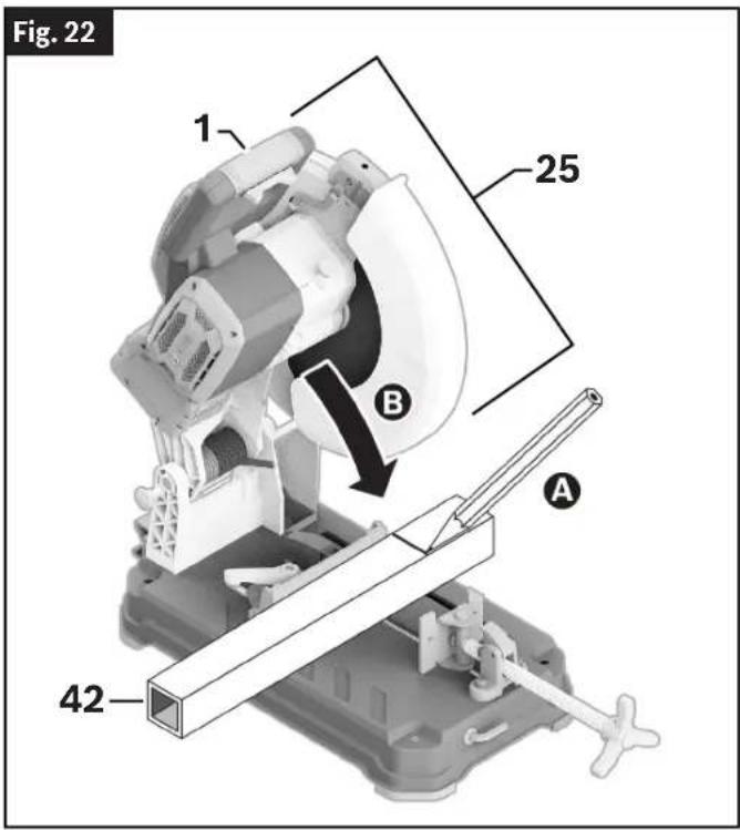
(Fig. 1, Fig. 2, Fig. 22, Fig. 23, Fig. 24, Fig. 25, Fig. 26, Fig. 27)
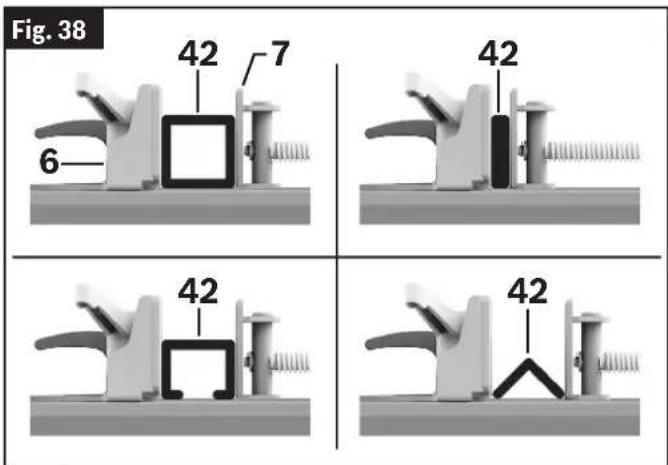
-
Draw a straight cutting line on the Workpiece 42 A. Slowly lower the Head Assembly 25 using the Main Handle 1 B.
-
Position the Workpiece 42 so that the teeth of the Blade 24 line up with the cutting line C. Hold the Workpiece 42 in this position and slowly guide the Head Assembly 25 back up D. Clamp the Workpiece 42 E.
Basic Saw Operations
- Turn on the laser beam by depressing the Power Switch 3 without pressing the Switch Lock-Off Release Button 2.
WARNING
Do not press the Switch Lock-OFF Toggle while adjusting
the laser. Pressing the Switch lock-OFF Toggle while pressing the Power Switch will turn the tool on and may result in personal injury and property damage.
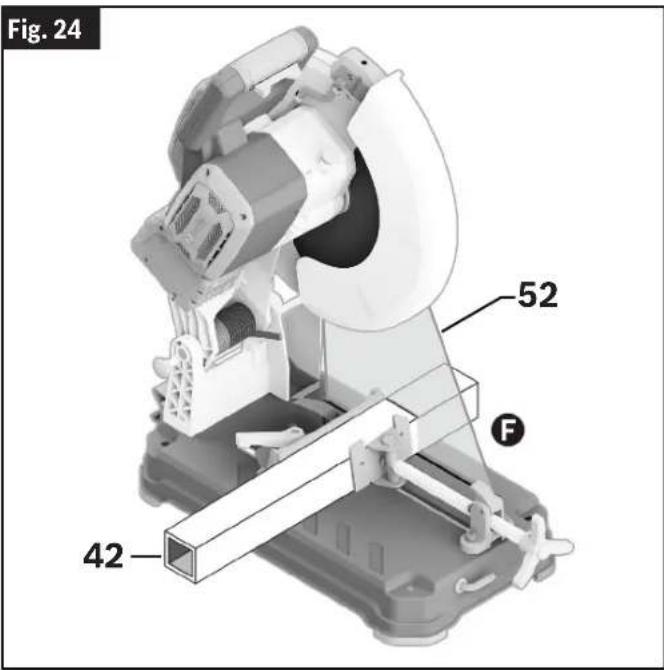
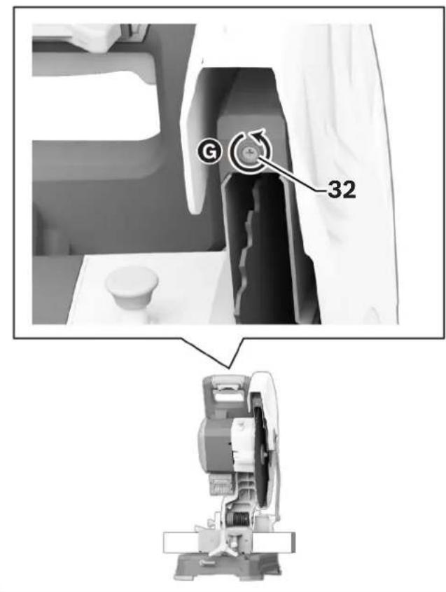
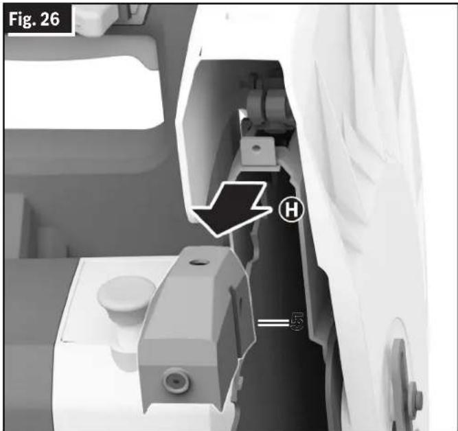
- Check to see if the Laser Beam 52 is aligned with the cutting line on the Workpiece 42 along its entire length F If not, raise the Lower Blade
text_image
Fig. 22 1 25 B A 42Guard 14, remove the Set Screw for Laser Protection Cap 32 by turning it counterclockwise G, and completely remove the Laser Protection Cap 5 from the tool H
- Allow the Lower Blade Guard 14 to return to the down position.
text_image
Fig. 24 52 F 42Fig. 25
text_image
G 32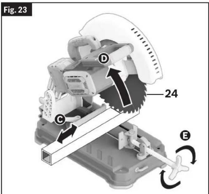
text_image
Fig. 23 24 D C EBasic Saw Operations
- On the top of the Laser 51, loosen the Laser Adjustment Screw 50 by turning it counterclockwise ①. The Laser 51 can now be moved by hand from right to left or from left to right depending on the adjustment needed ②.
- When the Laser 51 is properly aligned, tighten the Laser Adjustment Screw 50 by turning clockwise.
- Reinstall the Laser Protection Cap 5, and install the Set Screw for Laser Protection Cap 32 by turning it clockwise.
text_image
Fig. 26 H S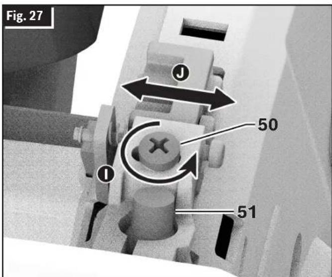
text_image
Fig. 27 J 50 I 51Overload Indicator
(Fig. 1, Fig. 2)
Your tool is equipped with an Overload Indicator 26 that will inform the operator of the current load conditions. Whenever the Power Switch 3 is turned on and load conditions are normal, the Overload Indicator 26 LED will not be illuminated.
- When using the tool and approaching overload conditions, the Overload Indicator 26 LED will illuminate yellow.
- If the tool continues to run in overload conditions for a sustained period of time, the electronic overload protection unit will shut the tool off.
- If the Blade 24 encounters a bind and completely stops, the Overload Indicator 26 LED will remain illuminated until the bind is cleared.
- If light overload conditions are present and the Overload Indicator 26 LED consistently illuminates, check the charge of the Battery Pack 29. Replace if needed. If the Battery Pack 29 is fully charged, run the tool at no load for approximately 10 seconds to allow the motor to cool down before continuing use.
Body and Hand Position
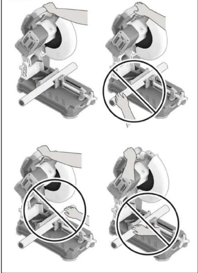
(Fig. 28)
WARNING To avoid injury, follow all statements identified below by the BULLET (•) symbol.
- Never place hands near cutting area on table or on workpiece.
• Always use Vise Clamp 7 to hold Workpiece 42 against the Base 18 and Vice Stop 6 when making cuts. - Do not support the workpiece by hand.
- Unclamp the workpiece ONLY after the Power Switch 3 has been released and blade has stopped completely.
- Keep feet firmly on the floor and maintain proper balance.
- Stand slightly to the side of the Saw Blade 24.
- Before making any cut, with the power off, lower the Blade 24 to preview the blade path - dry run.
WARNING Be aware of the path of the saw blade. Make a dry run with the saw OFF by conducting a simulated cutting cycle, and observe the projected path of the saw blade.
Basic Saw Operations
Dry Run
It is important to know where the blade will intersect with the workpiece during cutting operations.
Always perform the simulated cutting sequence with the power tool switched OFF to gain an understanding of the projected path of the saw blade Adjust the Vise Clamp 7, Vice Stop 6, and any clamps or fixtures being used to make sure that the lower guard and cutting action is not interfered with during cutting operation.
Workpiece Support
Using Workpiece Clamp
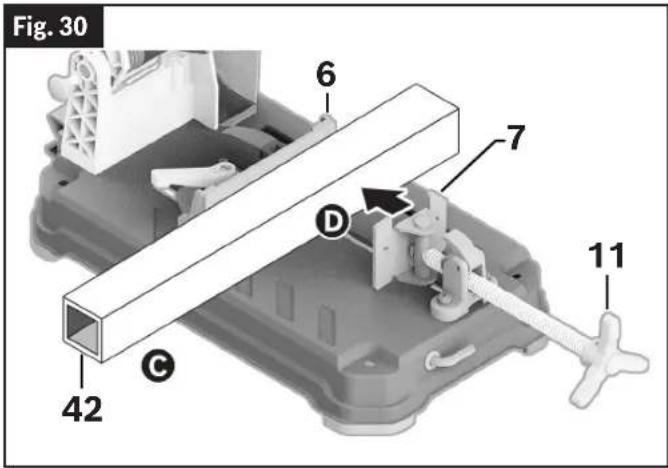
(Fig. 30, Fig. 31)
To secure a Workpiece 42, position the Workpiece 42 on the Base 18, making sure that it is resting fully on the Base 18, and clamp it firmly between the Vise Clamp 7 and Vise Stop 6.
Fig. 28
text_image
Technical diagram showing four steps of a cutting machine operation with hand positions and no text labelsClamping the Workpiece
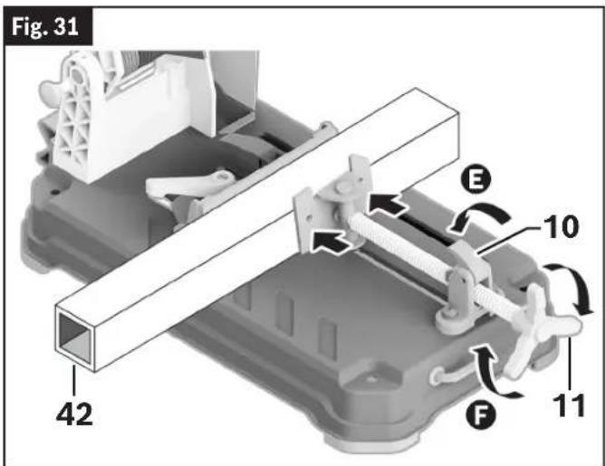
(Fig. 29, Fig. 30, Fig. 31)
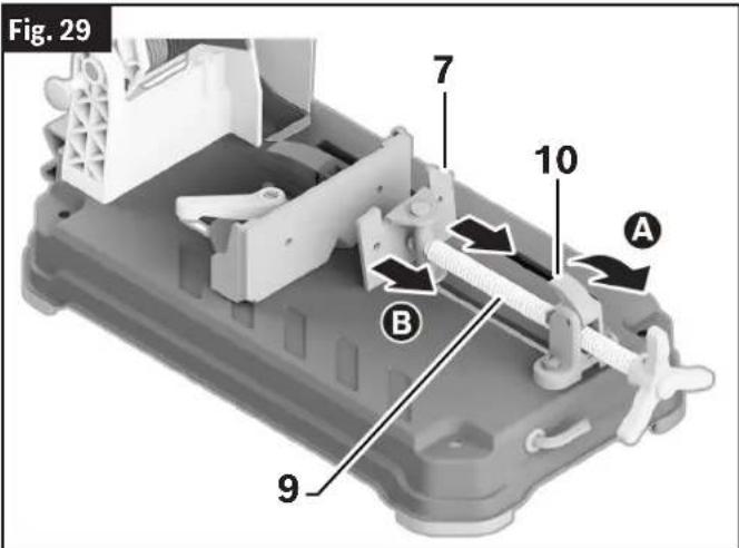
- Tilt Quick Release Lock Lever 10A up to release Vise Clamp 7.
- Pull the Vise Clamp 7 back B
- Place the Workpiece 42 between the Vise Stop 6 and the Vise Clamp 7 ©
- Slide the Vise Clamp 7 toward the Work piece 42 using the Vise Clamp Handle 11
- Tilt the Quick Release Lock Lever 10 back down E. Rotate the Vise Clamp Handle 11 clockwise F until the Workpiece 42 is secure.
Releasing the Workpiece
(Fig. 29, Fig. 30, Fig. 31)
- Rotate the Vise Handle 11 counterclockwise to loosen the Vise Clamp 7 from the workpiece.
- Tilt the Quick Release Lock Lever 10 UP.
- Using the Vise Clamp Handle 11, slide the Vise Clamp 7 away from the Workpiece 42.
text_image
Fig. 29 7 10 A B 9Basic Saw Operations
text_image
Fig. 30 6 7 D 11 42 C- Position the K-Adapter 28 over the top of the Vice Clamp 7 and slide the K-Adapter 28 down the face of the Vice Clamp 7 A
- Position the Workpiece 42 on the Base 18, making sure that the Workpiece 42 is resting fully on the Base 18 Ⓑ
- Clamp the Workpiece 42 securely between the K-Adapter 28 and Vise Stop 6 © D. (See "Clamping the Workpiece" on page 24 and "Releasing the Workpiece" on page 24.) To maintain workpiece stability and proper clamping, the top of the K-Adapter 28 should never be higher than the top of the Vise Clamp 53. Do not use a Spacer 54.
text_image
Fig. 31 42 E 10 F 11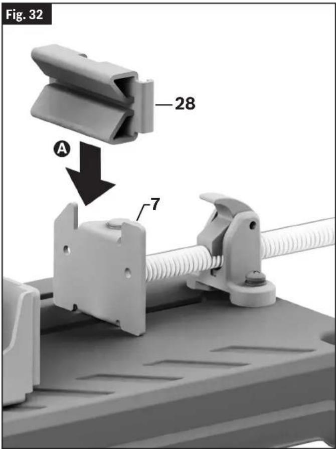
text_image
Fig. 32 28 A 7Using the K-Adapter
(Fig. 2, Fig. 32, Fig. 33, Fig. 34)
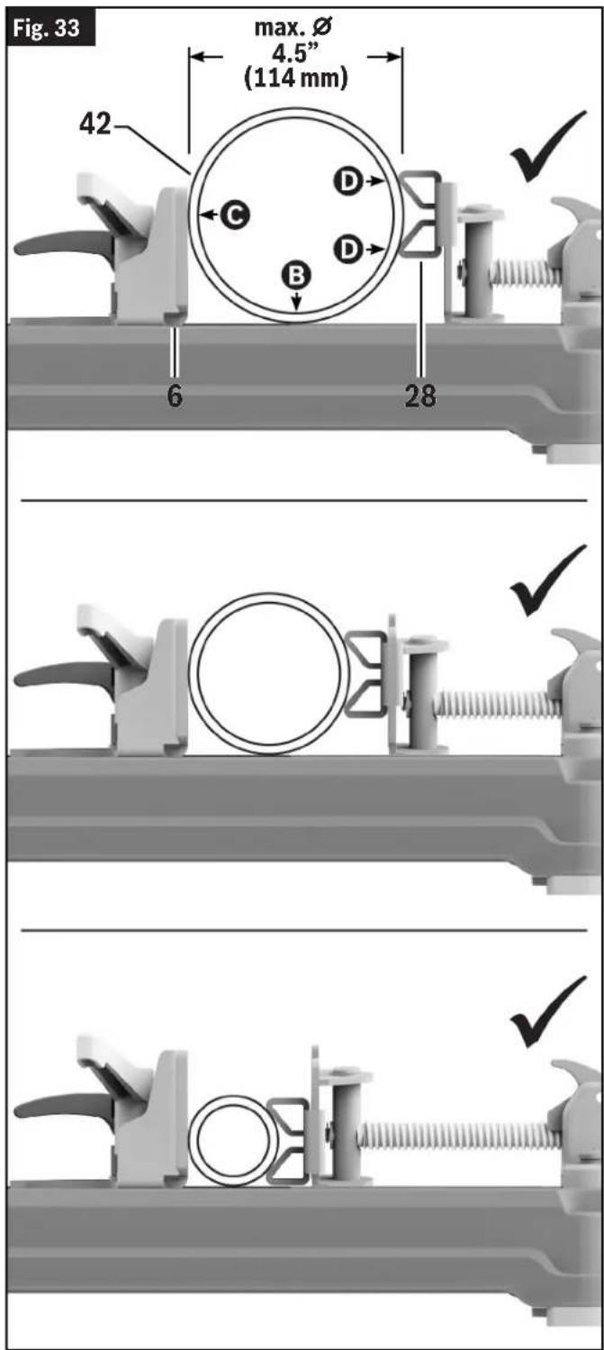
WARNING Use K-Adapter ONLY for round pipes with diameters ranging from the MINIMUM of 2" (51 mm) to the MAXIMUM of 4.5" (114 mm). Cutting round pipes with diameters smaller or larger than this diameter range may result in workpiece instability and kickback.
WARNING Always make sure that round workpieces rest on the Base and are clamped firmly between the Vise Stop and the K Adapter. Improperly clamped workpieces may roll or become unstable during the cut.
Your tool is equipped with a K-Adapter 28 intended to provide secure clamping of pipes with diameters ranging from the minimum of 2" (50.8 mm) to the maximum of 4.5" (114.3 mm).
To use the K adapter:
- Remove the K-Adapter 28 from its storage location on the rear of the tool's Base 18.
Basic Saw Operations
text_image
Fig. 33 max. Ø 4.5" (114 mm) 42 C D B 6 28 ✓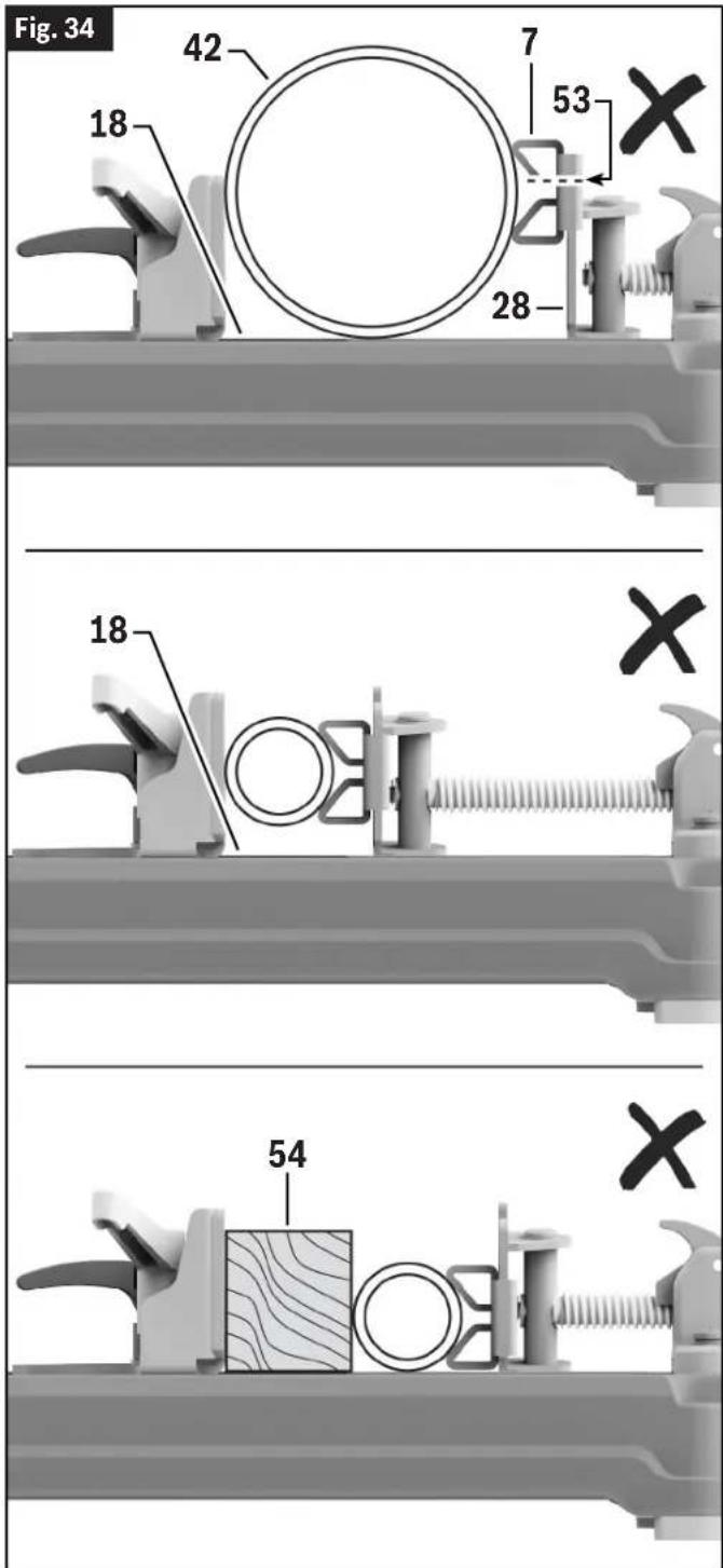
text_image
Fig. 34 42 7 53 18 28 18 54Basic Saw Operations
Material Positioning and Clamping
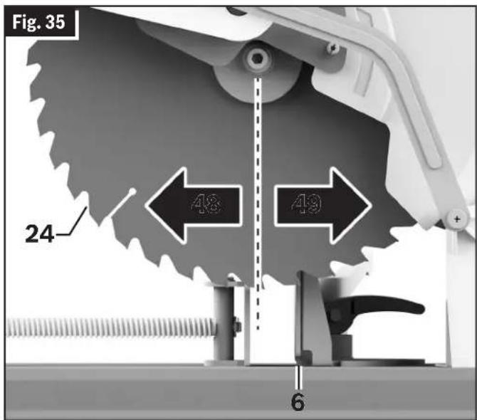
(Fig. 1, Fig. 35, Fig. 36)
Position the Workpiece 42 so it will be cut on the downstroke of the Blade 24. Downstroke cutting occurs in front of the blade center line 48 while upstroke cutting behind the blade center line 49.
WARNING Use appropriate clamping to restrain vertical movement of the workpiece when upstroke cutting is possible. Upstroke of the blade tends to pull the workpiece up from the vise and may result in serious damage to the tool and possible personal injury.
- Long workpieces must be supported with an auxiliary workpiece support to prevent sagging.
- Always securely clamp the workpiece with the Vise Clamp 7 and Vise Stop 6. (See “Clamping the Workpiece” on page 24.)
Long Workpiece Support
(Fig. 37)
WARNING Do not use another person as a sub stitute for a table extension or as additional support. Unstable support for the workpiece can cause the blade to bind or the workpiece to shift during the cutting operation, causing you to contact the spinning blade.
WARNING Long workpieces have a tendency to tip over unless clamped down and properly supported from underneath.
Support long Workpieces 42 to prevent sagging.
Use an Auxiliary Workpiece Support 43 for long Workpieces 42, opposite the Cut-Off End 44.
Blocks – Long Workpieces 42 need extra support. The base height is 2-5/8" (66 mm). Cut two 2x4 pieces to 2-5/8" in length and fasten together. Boards of this thickness and height can be used to create auxiliary support extensions for long Workpieces 42.
Clamps - Other hold-down devices such as C-clamps can be used to hold the Workpiece 42 firmly against the Base 18 and the Vise Stop 6. Make sure the clamps are clear of the cutting path.
text_image
Fig. 35 24 48 49 6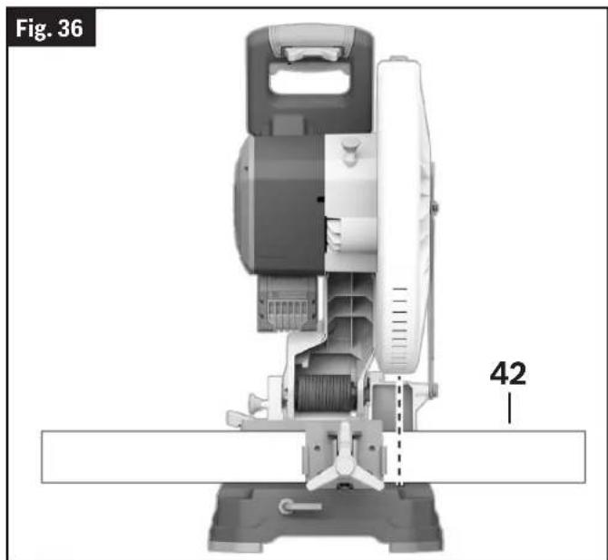
natural_image
Technical diagram of a mechanical device with labeled part 42, showing internal components and alignment lines (no readable text or symbols beyond labels)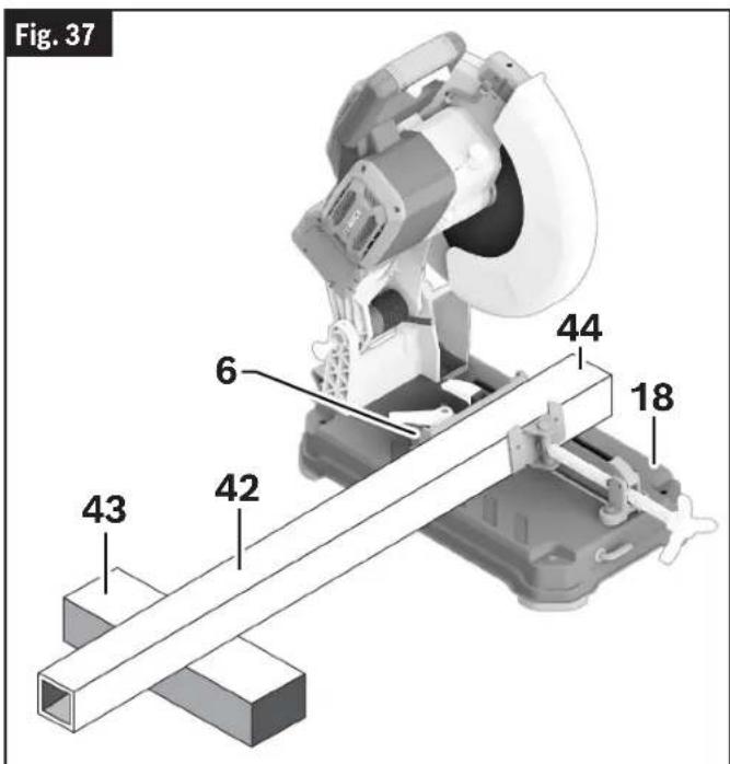
text_image
Fig. 37 6 44 18 42 43Basic Saw Operations
Tips for Using the Dry Cut Saw
(Fig. 30, Fig. 31, Fig. 36, Fig. 38)
Life of the dry cut saw Blade 24 will depend proper use of the saw. In order to achieve optimal saw Blade 24 performance, please read and follow the procedures below:
- Do not force the Blade 24 into the Workpiece 42 to be cut.
- Only cut the Workpiece 42 within the specified capacity for the saw Blade 24.
- Let the tool reach full speed before starting the cut.
- NEVER stop and restart with the Blade 24 in contact with the Workpiece 42. This could break the carbide teeth.
- Check the carbide saw Blade 24 regularly for abrasion and broken carbide teeth. If a Blade 24 becomes dull due to wear and/or broken teeth, replace it immediately.
- Clamp the Workpiece 42 correctly and ensure that is it centered relative to the Blade 24.
See “Clamping the Workpiece” on page 24 and “Material Positioning and Clamping” on page 27.
Making a Cut
Making a Chop Cut
(Fig. 1, Fig. 3)
A "chop cut" is a cross cut at 0^ miter angle.
Follow these instructions for making your chop cut:
- Pull the Head Assembly Lock Pin 15 and let the head assembly rise to the top position.
- Properly position Workpiece 42. Make sure Workpiece 42 is clamped firmly (See "Clamping the Workpiece" on page 24.)
- Activate the Power Switch 3. Lower the Head Assembly 25 and make your cut.
- Wait until Blade 24 comes to a complete stop before returning Head Assembly 25 to the raised position and/or removing Workpiece 42.
Making a Miter Cut
(Fig. 1, Fig. 3, Fig. 37)
A miter cut is a chop cut made at any miter angle in the range from 0 to 45°.
Follow these instructions for making your miter cut:
- Position the Vise Stop 6 for your miter cut by following the steps in "Adjusting the Vice Stop for Miter Cutting" on page 17.
- Properly secure the Workpiece 42 by following the steps in "Using Workpiece Clamp" on page 24.
- Follow the steps in "Making a Chop Cut" above.
- Wait until the Blade 24 comes to a complete stop before returning the Head Assembly 25 to the raised position or removing the Workpiece 42.
Cutting Banded Steel Stud Bundles
(Fig. 14, Fig. 39, Fig. 40)
WARNING Cut only full and banded bundles of steel studs with this
dry cut saw. Unbanded steel stud bundles, or bundles of any other material profile, such as rebar, may not clamp properly. Cutting improperly clamped workpieces may result in workpiece instability, kickback, tool damage, and serious personal injury.
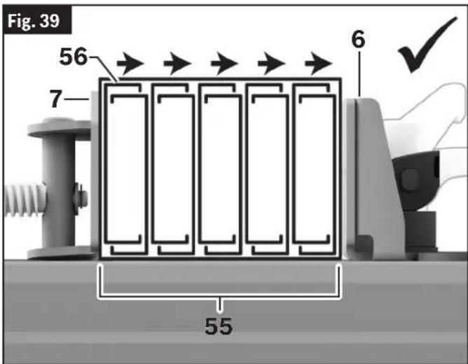
This dry cut saw can chop cut Banded Steel Stud Bundles 55 at 0° when the Vise Stop 6 is set in the Steel Stud Bundle Position 46. Banded Steel Stud
Basic Saw Operations
Bundles 55 must be supported and clamped properly before the cut is made.
Follow these steps to prepare to cut a Banded Steel Stud Bundle 55.
- Place and support the Banded Steel Stud Bundle 55 according to instructions in "Long Workpiece Support" on page 27.
Make sure to orient the Banded Steel Stud Bundle 55 with the Top Flanges or Legs of the Studs 56 pointing towards the Vise Stop 6. Orienting the Top Flanges 56 towards the Vise Clamp 7 will result in the flanges being deformed and/or torn by the blade during cutting.
- Clamp the Banded Steel Stud Bundle 55 following the instructions in "Clamping the Workpiece" on page 24. Make sure that the saw and bundle are stable and secure after clamping. Tighten the Vise Clamp 7 so that the studs are visibly compressed and flex slightly. To avoid permanent deformation, do not overtighten.
text_image
Fig. 39 56 7 6 55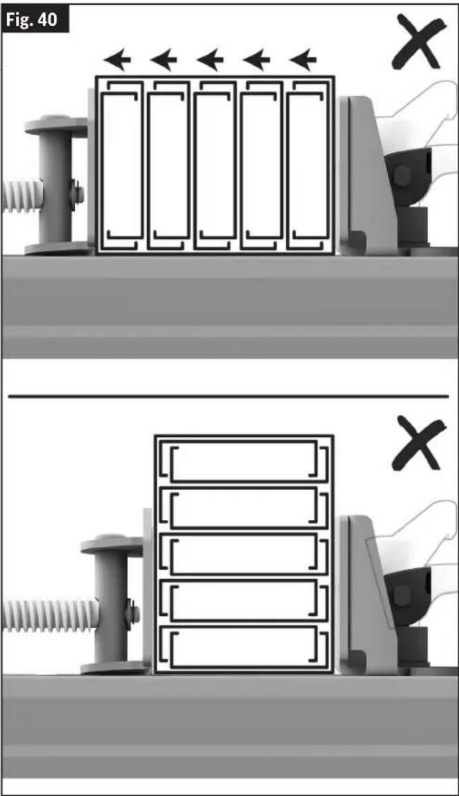
text_image
Fig. 40 X XBasic Saw Operations
Emptying the Chip Collector
(Fig. 41)
The Chip Deflector 23 is located on the rear right side of the tool. It is used to collect metal chips and other debris generated during the cutting process.
To maintain operational safety and efficiency, the accumulated chippings should be removed from the tool when the Chip Collector 27 is approximately 2/3 full.
- Place the Chip Collector Locking Latch 33 into the up/unlock position A
- Slide the Chip Collector 27 out of the tool, and discard the metal chips and other debris in an environmentally responsible way.
- Reinstall the Chip Collector 27 back into its location below the Chip Deflector 23.
- Place the Chip Collector Locking Latch 33 into the lock position. Before using the tool again, make sure it is seated firmly.

text_image
Fig. 41 23 23 27 33 A B 27Maintenance and Lubrication
WARNING To avoid possible injury, disconnect battery pack before performing any assembly, adjustments or repairs.
Service
⚠ WARNING All repairs, electrical or mechanical, should be attempted only by trained repairmen. Contact the nearest Factory Service Center or Authorized Service Sta-the blade is dull or has missing teeth. Replace the tion or other competent repair service. Use onlyblade if any teeth are missing, loose, or dull.
identical replacement parts, any other may create a hazard. Remember, blades are designed to cut, so handle carefully.
Batteries
Be alert for battery packs that are nearing their end of life. If you notice decreased tool performance or significantly shorter running time between charges then it is time to re place the battery pack. Failure to do so can cause the tool to operate improperly or damage the charger.
Cleaning
WARNING To avoid accidents, always disconnect the tool from the power supply before cleaning or performing any maintenance. The tool may be cleaned most effectively with compressed air. Always wear safety goggles when cleaning tools with compressed air.
Ventilation openings and switch levers must be kept clean and free of foreign matter. Do not attempt to clean by inserting pointed objects through openings.
Check regularly to make sure the lower guard and all moving parts are working properly.
Remove accumulated chips from working parts by blowing with compressed air or wiping with a damp cloth.
CAUTION Certain cleaning agents and solvents damage plastic parts.
Some of these are: gasoline, carbon tetrachloride, chlorinated cleaning solvents, ammonia and household detergents that contain ammonia.
Care of Blades
Blades can quickly become dull or lose teeth. If you find yourself forcing the saw forward to cut instead of just guiding it through the cut, chances are -the blade is dull or has missing teeth. Replace the yblade if any teeth are missing, loose, or dull.
Remember, blades are designed to cut, so handle carefully.
Tool Lubrication
Your Bosch tool has been properly lubricated and is ready to use. It is recommended that tools with gears be regreased with a special gear lubricant at every brush change.
Periodically lubricate moving parts with a silicone, or light oil spray. Do not use grease because it tends to attract and hold metal shavings.
Bearings
All bearings in this tools are lubricated with a sufficient amount of high grade lubricant for the life of the unit under normal operating conditions. No further lubrication is required.
Troubleshooting
Troubleshooting Guide - Electrical
| Problem | Cause | Corrective Action |
| Brake does not stop blade in about 5 seconds. | Blade bolt loose. Tighten blade bolt. | |
| Other. Authorized service. | ||
| Motor does not start. | Battery pack not charged. Charge | battery if needed. |
| Battery pack not installed properly. | Confirm battery is locked and secured to the tool. | |
| Battery pack temperature is too hot or cold for operation. | Let battery sit a few minutes or until it reaches normal operating temperature. | |
| Electronic Motor Protection turned tool off. | Remove battery and replace. | |
| Burned out switch. | Let tool sit a few minutes or until it reaches normal operating temperature. | |
| Other. | Have switch replaced by an Authorized Bosch Service Center or Service Station. | |
| Overload Indicator LED flashes or stays illuminated. | Tool is in an overload condition | Decrease pressure on Head Assembly and cut material slowly. |
| Tool is over heated. Let tool cool | down. | |
| Battery is over heated. Exchange | the battery. | |
| Blade binds. | Improper operation. See “Basic Saw Operations” starting on page 21. |
Troubleshooting Guide - General
| Problem | Cause | Corrective Action |
| Inaccurate cuts. | Vise Stop incorrectly positioned. | Check position and adjust. See “Adjusting the Vise Stop” on page 15. |
| Incorrect miter angle. | Check position and adjust. See “Adjusting the Vise Stop” on page 15. | |
| Excessive pressure used when cutting | Reduce cutting force, allow the blade do the work. | |
| Work piece is moving. | Clamp workpiece securely. See “Clamping the Workpiece” on page 24.) |
Troubleshooting
| Problem | Cause | Corrective Action |
| Head assembly will not fully raise or blade guard will not fully close. | Head assembly lock pin is engaged. | Pull out the head assembly lock pin, allowing head assembly to go up. See “To Disengage the Head Assembly Lock Pin” on page 15. |
| Chip accumulation. | Clean head assembly. | |
| Authorized service. | ||
| Blade binds, jams. Rough cuts. | Improper operation. | See “Basic Saw Operations” starting on page 21. |
| Dull blade. Replace or sharpen blade. | ||
| Improper blade. | Replace with 14" (355 mm) diameter blade designed for material being cut. | |
| Bent blade. Replace blade. | ||
| Tool vibrates or shakes. | Saw blade not round. Replace blade. | |
| Saw blade damaged. Replace blade. | ||
| Saw blade loose. | Check that blade is properly seated on the inner washer. See “Removing and Installing the Blade” on page 13. | |
| Tool not mounted securely to stand or work bench. | Tighten all mounting hardware. See “Permanent Attachment to Work-bench” on page 19. | |
| Workpiece not clamped properly. | See “Clamping the Workpiece” on page 24. | |
| Other. Authorized service. | ||
| Blade does not cut completely through workpiece. | Replacement blade is less than 14" (355 mm) diameter. | Change to a blade that is fully 14" (355 mm) diameter. |
| Vice Stop 6 is in the incorrect cutting position. | Reposition the Vice Stop to the correct cutting position. See “Material Positioning and Clamping” on page 27. |
Maintenance et lubrification....63
Service après-vente....63
Piles 63
Nettoyage....63
Entretien des lames....63
text_image
Fig. 8 19 ©natural_image
Mechanical tool with circular component and connecting rod, no visible text or symbolsRéglages
Fig. 14
text_image
Technical diagram of a mechanical assembly with labeled parts including bolts, springs, and a motor componentnatural_image
Technical illustration of a mechanical assembly with no visible text or symbolsnatural_image
Technical diagram of a mechanical device with labeled part 42, showing internal components and alignment lines (no readable text or symbols beyond labels)text_image
Fig. 40 X Xtext_image
Fig. 8 19 ©natural_image
Mechanical tool with a white cutting or grinding machine and attached base (no visible text or symbols)Ajustes
Fig. 14
natural_image
3D mechanical assembly diagram showing internal components like a fan, housing, and clamping device (no text or symbols)text_image
Technical diagram showing four steps of a mechanical assembly with hand operating and no tool crossed out, labeled in Chinese.hoja de sierra.
natural_image
Technical diagram of a mechanical device with labeled part 42, showing internal components and alignment lines (no readable text or symbols beyond label)text_image
Fig. 40 X XThis page was intentionally left blank.
This page was intentionally left blank.
For details on the terms of the limited warranty for this product, go to https://rb-pt.io/PowerToolWarranty or call 1-877-BOSCH99.
GARANTIE LIMITÉE
© Robert Bosch Tool Corporation
1800 W. Central Road
Mt. Prospect, IL 60056-2230
1619PC4952 01/2025