
LRP S3 6-36x56 - Riflescope ZEISS - Free user manual and instructions
Find the device manual for free LRP S3 6-36x56 ZEISS in PDF.

| Brand | ZEISS |
| Model | LRP S3 6-36x56 |
| Category | Rifle scope |
| Magnification | 6x to 36x |
| Reticle focal plane | First focal plane (FFP) |
| Objective lens diameter | 56 mm |
| Exit pupil diameter | 8.8 mm to 1.6 mm |
| Twilight factor | 17.7 to 44.9 |
| Field of view | 6.8 m to 1.1 m / 100 m |
| Diopter adjustment range | +3 to -3 diopters |
| Eye relief | 8 to 9 cm |
| Parallax adjustment range | 10 m to infinity |
| Elevation adjustment range (MRAD) | 32.00 MRAD |
| Lateral adjustment range (MRAD) | 11.63 MRAD |
| Click adjustment (MRAD) | 0.1 MRAD |
| Click adjustment (MOA) | 0.25 MOA |
| Main tube diameter | 34 mm |
| Eyepiece tube diameter | 45 mm |
| Objective tube diameter | 65 mm |
| Objective tube thread | M62 x 0.75 mm |
| Lens coating | LotuTec®, T* |
| Nitrogen filling | Yes |
| Waterproof | 400 mbar (4 m / 13 ft) |
| Operating temperature | -25 °C to +50 °C |
| Length | 384 mm |
| Weight | 1,107 g (39.1 oz) |
| Battery | CR 2032 3V lithium battery |
| Reticle | ZF-MRi (milliradian) or ZF-MOAi (minutes of angle) illuminated |
| Main features | Continuous magnification change, diopter adjustment, reticle illumination (red/green), parallax adjustment, elevation and windage turrets with ballistic stop and lock |
| Maintenance and cleaning | Clean the lenses with ZEISS solution; wash the exterior with lukewarm water; do not use aggressive solvents |
| Safety | Never aim at the sun or a laser source; ensure the firearm is unloaded before mounting; follow ZEISS safety instructions |
| Spare parts and repairability | Contact ZEISS customer service; battery replaceable by user |
| General information | Supplied with magnification lever, protective covers, Torx T8 key, cleaning cloth, safety instructions |
Frequently Asked Questions - LRP S3 6-36x56 ZEISS
User questions about LRP S3 6-36x56 ZEISS
0 question about this device. Answer the ones you know or ask your own.
Ask a new question about this device
Download the instructions for your Riflescope in PDF format for free! Find your manual LRP S3 6-36x56 - ZEISS and take your electronic device back in hand. On this page are published all the documents necessary for the use of your device. LRP S3 6-36x56 by ZEISS.
USER MANUAL LRP S3 6-36x56 ZEISS
Long-Range Precision Riflescope
EN Instructions for use / Customer Service and Warranty
Patents: www.zeiss.com/cop/patents
EN DE FR ES IT NL DK
FI HU PL SE RU JP CN | 06.2022

ZEISS products are famous for outstanding optical performance, precision workmanship, and long service life. Please observe the following instructions for use to obtain the best results from your riflescope and to ensure it remains as your preferred gear for many years to come.

WARNING!
Please note the enclosed safety instructions and regulatory information. You can also find them at:
www.zeiss.com/cop/safety

Table of Contents
| Table of Contents 3 |
| Scope of supply 4 |
| Technical data 5 |
| Description of the Components 6 |
| Changing the Magnification 8 |
| Focusing the Reticle / Diopter Adjustment 9 |
| Reticle Illumination 10 |
| Battery Replacement 12 |
| Parallax Adjustment 13 |
| Basic Mounting Instructions 14 |
| Leveling The Reticle 16 |
| Establishing a Sight-In Zero 18 | |
| Elevation Turret 20 | |
| How to Set the Ballistic Stop, Elevation 21 | |
| External Locking Windage Turret (ELWT) | 26 |
| How to Re-Index to Zero (ELWT) | 27 |
| Reticle Type ZF-MRi (FFP) | 32 |
| Reticle Type ZF-MOAi (FFP) | 34 |
| Accessories | 36 |
| Care and Maintenance | 38 |
| Customer Service and Warranty | 40 |
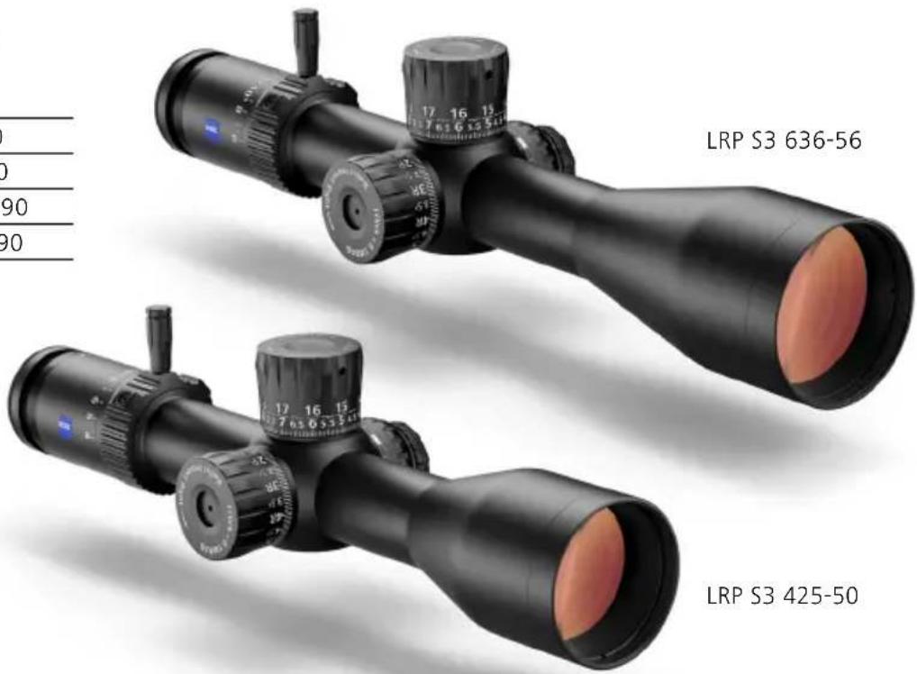
EN Instructions for use ZEISS LRP S3 425-50 | 636-56
Scope of supply
LRP S3 Order number
425-50 MRI 522675-9916-090
636-56 MRI 522695-9916-090
425-50 MOAi 522665-9917-090
636-56 MOAi 522685-9917-090
Scope of Supply
- Riflescope
- Throw Lever
- Protective lens cap
- Li battery 3V CR 2032
- Optical cleaning cloth
- User guide
- Safety information
- Torx* wrench (size T 8)
* Torx is a registered trademark of Acument Intellectual Properties, LLC.
| Technical data | 36-56 | ||
| Magnification 4x-25x6x-36x | |||
| Focal Plane First Focal Plane (FFP) | |||
| Effective lens diameter 50mm 56mm | |||
| Exit pupil diameter 7.1-20mm 8.8-1.6mm | |||
| Twilight factor 11.7-35.4 | 17.7-44.9 | ||
| Field of view | 9.5-1.6m/100m // 28.5-4.8ft/100yd | 6.8-1.1m/100m // 20.4-3.3ft/100yd | |
| Objective viewing angle | 5.4°-0.9° | 3.9°-0.6° | |
| Diopter adjustment range | +3/-3 dpt | ||
| Eye relief | 8-9 cm / 3-3.5 in | ||
| Parallax setting | 15-∞m / 16.4-∞yd | 10-∞m / 10.9-∞yd | |
| Elevation (E) + Windage (W) adjustment range | MRAD | E: 46.54 + W: 17.45 | E: 32.00 W: 11.63 |
| MOA | E: 160+ W: 60 | E: 110 + W: 40 | |
| Adjustment per click | MRAD | 0.1 | |
| MOA | 0.25 | ||
| Main tube diameter | 34 mm | ||
| Eyepiece tube diameter | 45 mm 45 mm | ||
| Objective tube diameter | 60 mm | 65 mm | |
| Objective Thread | M57×0.75mm | M62×0.75mm | |
| Coatings | LotuTec®, T* (T-Star) | ||
| Nitrogen filling | yes | ||
| Waterproof | 400mbar (4 m / 13 ft) | ||
| Operating temperature | -25/+50°C / -13/+122°F | ||
| Length (neutral diopter setting) | 340 mm / 13.4 in | 384 mm / 15.1 in | |
| Weight | 1,040g / 36.7 oz | 1,107 g / 39.1 oz | |
| Reticles (illuminated) | ZF-MRi (Milliradian) / ZF-MOAi (Minute of Angle) | ||
5Data above
EN Instructions for use ZEISS LRP S3 425-50 | 636-56
Description of the Components
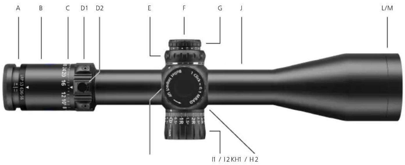
Features may vary, depending upon model configurations.
A Diopter Adjustment
B Ocular Housing
C Magnification Zoom Indicator
D1 Magnification Zoom Adjustment
D2 Throw Lever
E Parallax Adjustment
F Battery Housing
G Illumination On /Off and Adjustment
H1 Elevation Turret MRAD
H2 Elevation Turret MOA
I1 Locking Windage Turret MRAD
12 Locking Windage Turret MOA
J Main Tube
K Saddle area
L Objective
M Objective Thread
For the latest updates and information regarding our products, visit:
www.zeiss.com/precision-shooting

H1 - Elevation Turret MRAD
H2 - Elevation Turret MOA
I1 - Windage Turret MRAD

I2 - Windage Turret MOA
EN Instructions for use ZEISS LRP S3 425-50 | 636-56

WARNING!
Never look at the sun or a laser light source through the riflescope. This can cause severe injuries to your eyes.
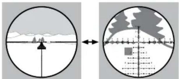
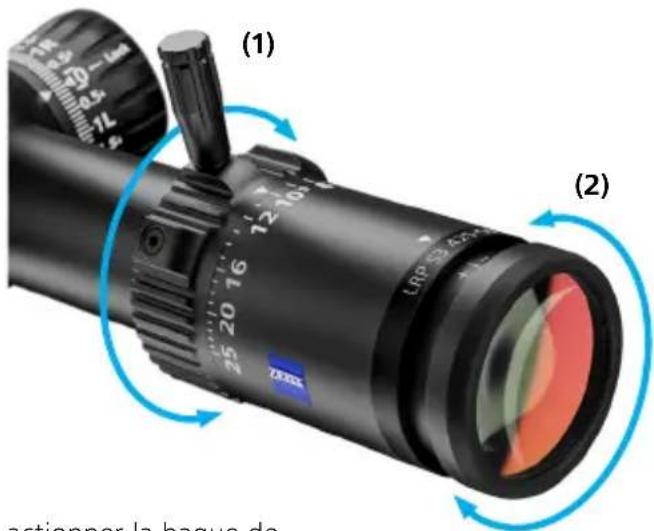
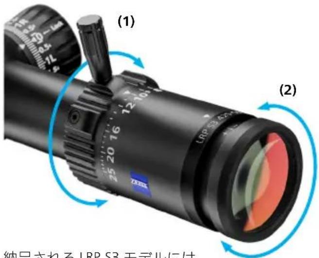
Changing the Magnification
The magnification adjustment allows to select the desired magnification setting (1a, 1b). Accomplish this task by rotating the adjustment ring (1).
natural_image
Two circular diagrams showing a landscape with mountains and a crosshairs, one with a scale bar and arrow, the other with a shaded region (no text or symbols)(1a) Low magnification
(1b) High magnification

The LRP S3 comes
with a magnification throw lever.
It can be installed into any of the three integrated ports of the magnification/zoom adjustment.
The user can elect to use the throw lever, or not.
This feature allows the shooter to select the appropriate position that works best for their application.
Focusing the Reticle / Diopter Adjustment
To adjust the eyepiece to establish an appropriate diopter setting, turn the eyepiece either inward or outward (2) to achieve the preferred setting (2b). If you plan to wear corrective vision glasses when shooting, then set this focus while wearing your corrective glasses or using contact lenses.
-
Begin at the highest magnification setting.
-
Set parallax to the infinity setting .
-
Look through the riflescope at a neutral colored background, such as a white or gray wall, or cover the objective lens with a light cloth to eliminate distracting background. Determine if the reticle is clear and in focus as soon as you view through the eyepiece. Note that staring
at the reticle for more than about two seconds during this setup will cause the eye to begin to compensate for focus, resulting in a false indication of the reticle's true focus. Try to assess a few seconds at a time, looking away for about 5-10 seconds, and then view again to determine results. The goal is to get a crisp and highly focused reticle image – without straining the eye.
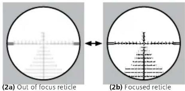
- If adjustment is necessary, follow these steps: Because of the way the eye accommodates, ideal results are typically obtained by turning the eyepiece inward until the reticle is slightly blurred (2a), then turning it outward until sharp focus is obtained (2b).
Once you are satisfied with the reticle's focus, memorize the position of the eyepiece for quick reference in the future.
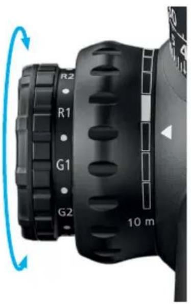
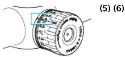
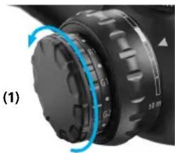
Reticle Illumination
Illumination is turned on by rotating the illumination adjustment knob to any of the 'R' or 'G' settings. The 'G' zone represents illumination in green. The 'R' zone represents illumination in red.
Illumination intensity control is variable. The numerical scale of '1' represents the lowest intensity setting, while '5' represents the maximum intensity setting. The 'off' setting is located between each numerical intensity setting.
As soon as the battery voltage decreases (becomes empty), the reticle illumination flashes. This is only visible in the high intensity levels, first in the green, then in the red illumination area.
natural_image
Close-up of a black mechanical device with labeled buttons (R1, R2, G1, G2) and a 10-meter scale indicator, showing rotational motion (no text beyond labels)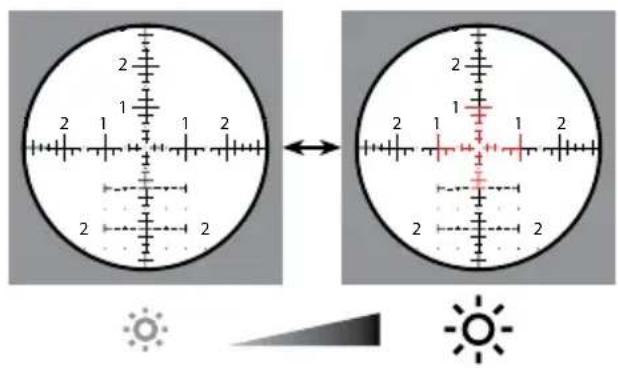
Illumination technology
If a slight movement/displacement of the illuminated part of the reticle is noticeable in unique shooting conditions, please ensure that the eye is properly aligned with the optical axis. This ensures that a precise shot placement can be achieved.
EN Instructions for use ZEISS LRP S3 425-50 | 636-56
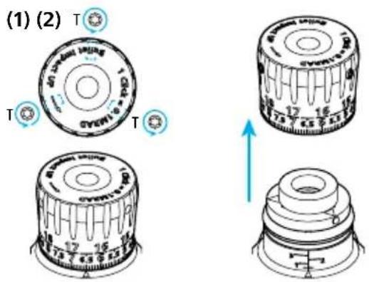
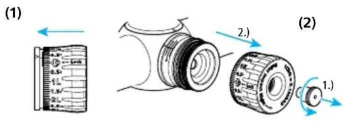
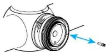
Battery Replacement
Inserting/removing the battery
To change the battery (model CR 2032), turn the cover (1) to the left (counterclockwise).
The battery is inserted with the positive (+) pole facing out. Then screw the cover (2) back on.
Make sure it is seated properly and check the condition of the sealing ring.
Replace the seal if it is damaged.
Note: If the riflescope will not be used for an extended period of time, remove the battery.

WARNING!
Please note the enclosed safety instructions and regulatory information about battery handling and disposal. You can also view them at:
www.zeiss.com/cop/safety

natural_image
Close-up of a black mechanical component with blue circular arrows indicating rotation or adjustment (no text or symbols)
natural_image
Close-up of a camera lens assembly showing internal components and a blue circular arrow indicating rotation (no text or symbols)(2)
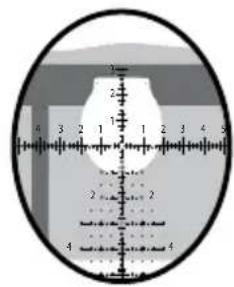
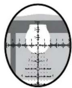
Parallax Adjustment
Parallax is the reticle's apparent movement in relation to the target as the user moves his eye across the exit pupil of the riflescope. This condition is caused by the target and the reticle appearing on different focal planes within the riflescope.
The goal is to remove the parallax sighting error by adjusting the focus setting via the parallax adjustment. If parallax is present, it will be noticeable by moving the eye left and right or up and down, and witnessing the reticle slightly move against the target. Parallax creates an aiming error.
Adjusting to Remove Parallax
Check for parallax with the rifle in a stable position while looking through the riflescope at a defined point on the target. To eliminate parallax, rotate the parallax adjustment until the reticle remains stable in relation to the target, regardless of head movement / eye placement.
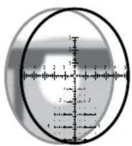
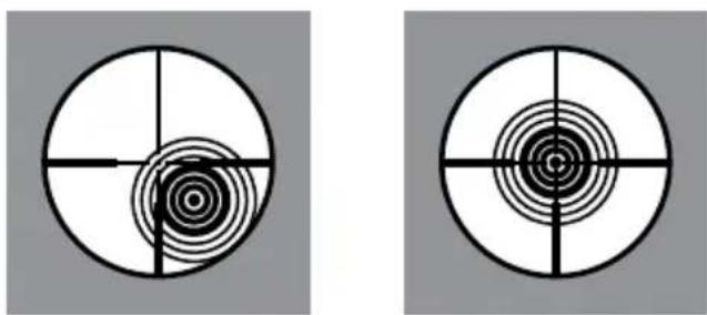
Image plane is behind the reticle (parallax present).

Image and reticle are located in a single plane (parallax absent).

Make sure your rifle is unloaded, the chamber is empty, and the action is open prior to installing your ZEISS riflescope.
Poor or improper mounting of the riflescope can cause equipment and personal damage, which can result in serious equipment damages, as well as personal injury or death.
Recoil is real energy, and it can be dangerous for the user! Please be certain that the installation provides maximum eye relief. Pay attention to this warning, especially when shooting uphill or from a prone position. Shooting conditions such as these can dramatically reduce eye relief.
If you are not familiar or comfortable with the following steps of the process, ZEISS suggests that these steps of the procedure be accomplished by a competent gun shop staff member, gunsmith, or professional entity.
Basic Mounting InstructionsWARNIN
Ring and Base Selection (Rings Equal 34 mm)
To optimize the performance of the riflescope and mounting solutions, ZEISS recommends the following:
■ Use a high-quality ring and base combination that properly fits the rifle as well as the riflescope model, e.g., ZEISS Precision rings.
Mounting the Base to the Action
Attach the base to the action, and follow the torque setting for the mounting screws provided by the manufacturer. Ensure the mounting screws and threaded holes are clean and free of grease and contaminants.
Mounting the Rings to the Base
Ensure that the rings' inside surfaces and the surface of the scope tube are clean and free of grease.
Do not place any other substance or material between the scope tube and the inner surface of the rings.
Ensure that the height of the rings will allow for adequate clearance of the objective and barrel surface. If you plan to use flip-up or pull-over lens covers, consider the additional space requirements. Install the rings on the base per manufacturer's specifications. Take care to ensure that the rings do not contact the main tube transition points of the ocular or objective. Ensure as well that the rings do not come into contact with the saddle portion of the riflescope.
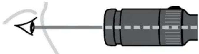
Mounting the Riflescope
- For the initial fit of the riflescope to the rifle, set the riflescope to the highest magnification. Place the riflescope in the rings as far forward as possible. Tighten the ring screws with minimal tension to gently but safely hold the riflescope
in position. This initial step should just allow the scope to move back and forth for step 2 listed below.
- Place the rifle in your normal shooting position. Place your head as far forward on the stock as you might position it in field use. Slowly move the riflescope back just to the point where the full field of view is obtained. ZEISS recommends mounting the riflescope at this position to ensure maximum eye relief.
Eye relief: 3"-3.5"/ \~8-9 cm
natural_image
Diagram of a mechanical component with a pointed tip and internal shaft (no text or symbols)Note: While wearing thick clothing, you may need to adjust your riflescope mounting location to accommodate for maximum eye relief.
Leveling The Reticle
For precise shot placement, the reticle and the rifle need to be squared or plumb to each other. This will reduce sighting errors that will be magnified as the distance to target is increased.
The reticles in ZEISS riflescopes are plumb with the flat surface of the bottom of the saddle area. To level the reticle using a plumb line, follow these helpful steps:
- Ensure the rifle is unloaded and is level and affixed in a steady rest or sandbags throughout this procedure.
-
While viewing through the riflescope, reference a plumb line or plumb target frame at a suggested distance of approximately 100 meters / yards.
-
From the shooting position, center/align the reticle on the plumb line for reference and rotate the riflescope in the rings until the vertical line of the reticle is parallel with the plumb reference line.
When all is adjusted and aligned properly, finalize the tightening of the ring screws evenly to secure the riflescope in the rings.
Torque the ring screws to the recommended torque settings. Your ZEISS riflescope should now be mounted and secured in the proper position.
Establishing a Sight-In Zero
Please visit www.zeiss.com/lrp-s3 or ZEISS Hunting YouTube channel for a video tutorial on this process and setting methods that can maximize the performance of your Ballistic Stop configured riflescope.
- Confirm that the rifle is unloaded and the chamber is empty. Affix the rifle in a steady rest and remove the bolt assembly.
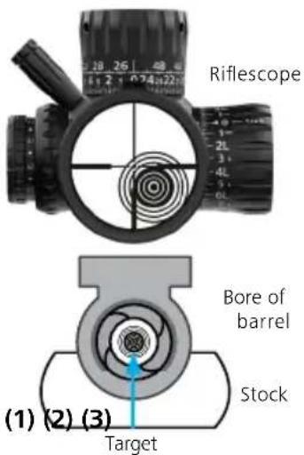
- While looking down the bore's centerline from the action end (1), center the target in the bore. The target should appear in the center of the barrel's bore (2). With the rifle held in a position not allowing it to move, adjust the elevation and windage turrets until the reticle is centered on the target (3), keeping the target centered in the bore during this process (ensure the windage turret is in the unlocked position, see page 26).
Adjust the elevation and windage turrets until the reticle is centered on the target, keeping the target centered in the bore during this process.
natural_image
Two identical circular diagrams with concentric rings and crosshairs, no text or symbols present.- With the bore sighting process completed, you can begin live firing sight-in at the respective 25, 50, or 100 meters / yards. ZEISS recommends 2–3 confirmation shots. After the point of impact is confirmed, proceed to the next step. The 2–3 shots should be located somewhere on your sighting target.
-
Now aim the rifle and center the reticle on the intended sight-in target from step 3. While holding the rifle steady on the center of the target and looking through the riflescope, adjust the elevation and windage turrets until the reticle is aligned in the center of the 2-3 shot group from step 3.
-
After completing step 4 to confirm sight-in adjustments, shoot a three-shot group at the sight-in target. The center of the group should represent the center of aim. Once your zero is established, ZEISS suggests a final confirmation of 2–3 shots on target at your sight-in distance. See the "NOTE" section below.
-
a) Reindex the elevation turret to zero and set the Ballistic Stop (see page 21). b) Reindex the windage turret to zero and lock the turret (see page 27).
NOTE: Many variables can impact your point of aim and zero, i.e., different types of ammunition, ammunition temperature, barrel temperature, and wind. Please zero-in under stable conditions and parameters.
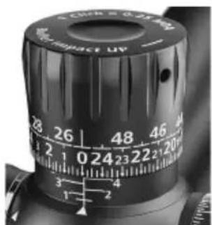
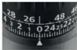
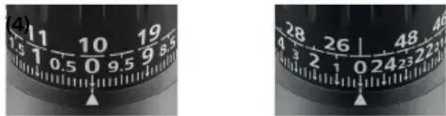
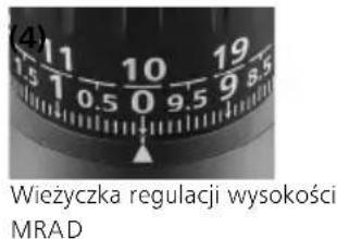
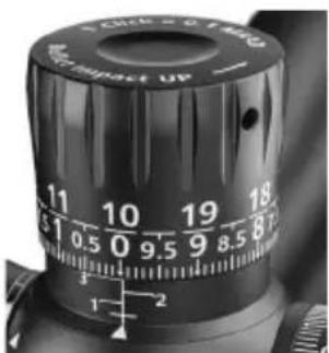
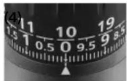
Elevation Turret
The turret incorporates a mechanically lifting design that allows for multi-turn functionality.
Counterclockwise (CCW) adjustment for upward bullet impact on target (1) and clockwise (CW) adjustment for downward bullet impact on target (2).
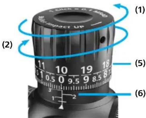
(3)
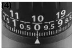
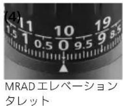
Elevation Turret MRAD Elevation Turret MOA
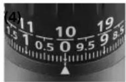
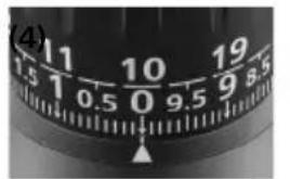
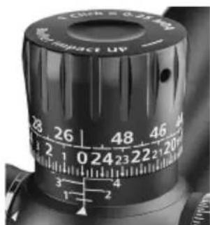
Depending upon the configuration of your riflescope, the turret will be engraved with either milliradian (MRAD) (3) or minute of angle (MOA) (4) value of adjustment.
The dual-row engraving allows for quick visual tracking references for most short-to-long-distance shooting scenarios (5). The current turret rotation will be shown by the numbers (6).
Zero is represented with a horizontal line at the top of the delta indicator.
The ZEISS LRP S3 models are shipped from the manufacturing facility
- with the elevation turret set at the middle of the riflescope's total elevation travel adjustment value.
- with the Ballistic Stop set to allow for total elevation travel value.
The per-click value will be:
■ MRAD turrets = 0.1 MRAD - per click
■ MOA turrets = 0.25 MOA - per click
The complete travel of one full rotation will be:
■ MRAD turrets = 10 MRAD - per rotation
■ MOA turrets = 25 MOA – per rotation
The total travel adjustment value will be:
■ MRAD turrets = total elevation travel
425-50: 46.5 MRAD
636-56: 32.0 MRAD
■ MOA turrets = total elevation travel
425-50: 160 MOA
636-56: 110 MOA
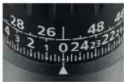
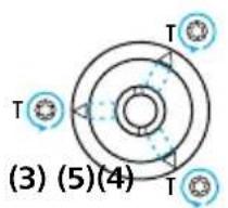
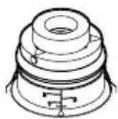
How to Set the Ballistic Stop, Elevation
NOTE A: The Ballistic Stop allows the elevation turret to be aligned with the '0' reference when set.
NOTE B: The elevation turret cap is removable via three Torx T8 set screws which require being loosened to access the Ballistic Stop assembly.
NOTE C: Once the Ballistic Stop assembly is exposed, you will need to loosen three additional Torx T8 set screws for setting the Ballistic Stop.
Attention: Before attempting to zero your rifle, always make sure the firearm is unloaded.
Step 1: It is assumed that the riflescope is, and that the turret settings are, now sighted-in to the preferred zeroing distance. It is suggested that the rifle and scope be well secured to prevent any unnecessary movement and allow for both hands to be free to work.
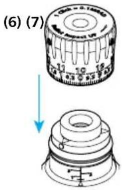
Step 2:
a) Using the appropriate Torx T8 wrench, loosen the three set screws on the turret cap by turning each of them counterclockwise for one rotation (1).
b) Remove the elevation turret cap by lifting off the turret cap assembly (2).
c) You may feel slight resistance while lifting off the cap.
d) Place the turret cap aside on a clean surface. Take care to keep the inside of the turret cap clean and free of debris.
e) The Ballistic Stop assembly is now exposed. Maintain the cleanliness of the Ballistic Stop assembly.
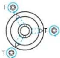
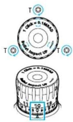
Step 3: Loosen the three T8 set screws, marked with a delta atop the Ballistic Stop disc, counterclockwise for one rotation (3). Press down firmly on the disc until stopped and bottomed out (4).
Then rotate the Ballistic Stop disc clockwise until it comes to a hard stop (4). Ensure the two pins remain in contact with each other—not allowing further downward adjustment of the turret. Now tighten the three T8 set screws atop the Ballistic Stop disc, indicated with a delta (5). The torque value setting for these screws is 1 Nm or 8.85 in lbs.
NOTE: Do not overtighten the screws. Improper torque settings can cause the turret's cap to slip during turret adjustment.
Step 4: Be sure the entire assembly is clean and free of debris and put the turret cap on again. Center it over the turret body assembly and press it down lightly into position (6). Maintain a slight downward pressure on the cap, align the cap's engraved numerical "0"/zero index mark with the vertical engraved center line on the turret's base housing, and tighten the three T8 set screws clockwise (7). The torque value setting for these screws is 1 Nm or 8.85 in lbs.
Step 5: When completed, it is advised to test the 'stop' setting. To do so, try to rotate the elevation turret beyond the newly established 'stop'.
You should not be able to rotate past the newly established Ballistic Stop setting. It should render a solid and robust stop, with no further click feeling or adjustment.
Step 6: Once satisfied that the Ballistic Stop is set properly, confirm the rifle and scope zero by firing 2–3 additional shots on the sight-in target, at the sight-in distance, to reconfirm the previously established zero.
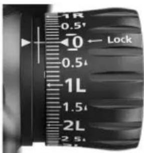
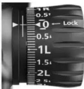
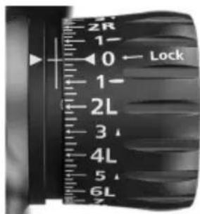
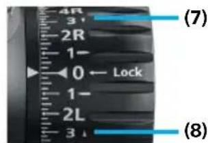
External Locking Windage Turret (ELWT)
The turret incorporates a multi-turn functionality. From the UNLOCKED position, counterclockwise (CCW) adjustment is for rightward bullet impact on target (1), and clockwise (CW) adjustment is for leftward bullet impact on target (2).
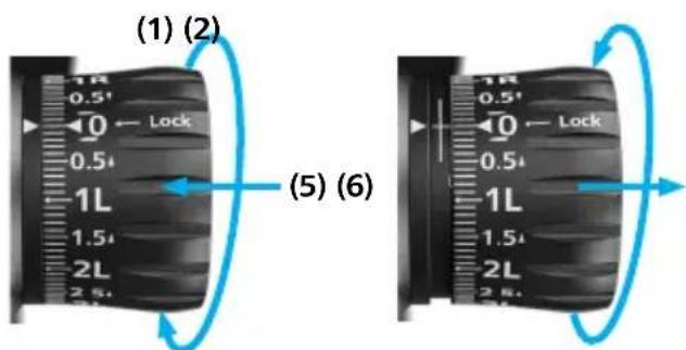
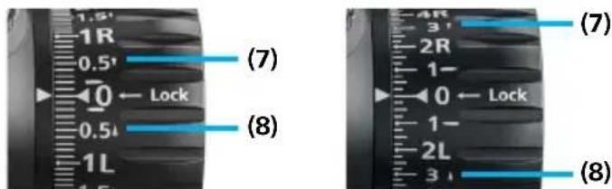
(3) (4) Windage Turret MRAD Windage Turret MOA
Depending upon the configuration of your rifle-scope, the turret will be engraved with either milliradian (MRAD) (3) or minute of angle (MOA) (4) value of adjustment.
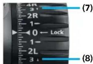
The locking feature protects the chosen turret setting by pushing in on the turret knob (5).
To adjust the turret setting, unlock the turret by pulling out on the turret knob (6).
The arrow indicators next to the respective engraving of 'R' (7) or 'L' (8) indicate the necessary direction to rotate the turret to get the bullet to impact further right 'R' or further left 'L'.
The ZEISS LRP S3 models are shipped from the manufacturing facility
- with the windage turret set at the middle of the riflescope's total windage travel adjustment value
- with the locking collar set in the 'locked' position.
The per-click value will be:
■ MRAD turrets = 0.1 MRAD - per click
■ MOA turrets = 0.25 MOA - per click
The complete travel of one full rotation will be:
■ MRAD turrets = 10 MRAD - per rotation
■ MOA turrets = 25 MOA – per rotation
The total travel adjustment value will be*:
■ MRAD turrets = total windage travel 425-50: 15.45 MRAD 525-56: 11.63 MRAD
■ MOA turrets = total windage travel 425-50: 60 MOA 525-56: 40 MOA
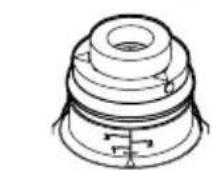
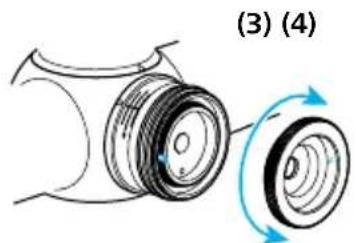
How to Re-Index to Zero (ELWT)
NOTE A: The windage turret incorporates a lock system and windage limiter feature. The turret can be removed.
NOTE B: The Torx T8 cap screw for the ELWT needs to be loosened - AND then removed for re-indexing purposes.
NOTE C: If desired, the Windage Limiter Pin can be removed by the end-user.
* This is only valid if the limiter pin will be removed (otherwise it is limited to 0.5 rotations in each direction)
Attention: Before attempting to zero your rifle, always make sure the firearm is unloaded.
Step 1: It is assumed that the riflescope is zeroed and that the turret settings are now sighted-in to the preferred zeroing distance. It is suggested that the rifle and scope be well secured to prevent any unnecessary movement and allow for both hands to be free to work.
Step 2: You will most likely need to adjust the ELWT beyond the factory settings for your zeroing needs first. Then you will need to re-index to zero once you have sighted-in your riflescope. This is typical of all riflescopes. The adjustment process is simple, but it does require your attention to detail.
While zeroing your rifle, if you have adjusted your ELWT and have encountered the
windage limiter—which feels like a hard stop—you will need to remove the ELWT turret cap in order to achieve further adjustment for zeroing.
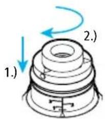
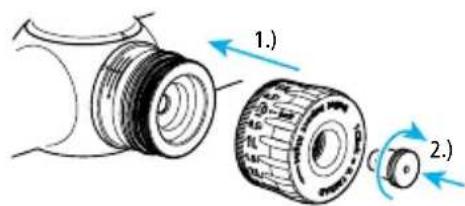
Step 3: Remove the ELWT adjustment cap by first ensuring the turret is in the locked position (pushed in) (1).
Fully loosen the Torx T8 screw centered on the face of the ELWT by turning it counterclockwise multiple times (2) 1.).
Step 4: Then remove the adjustment cap from the turret assembly (2) 2.). Set it aside on a clean surface. Make sure not to contaminate the internal surfaces of the cap or the exposed mechanics and O-ring of the turret.
Step 5: With the cap removed, the windage limiter disc is now exposed. Remove it by pulling it away from the turret assembly.
Rotate the disc to where the stop pin is indexed 180^ from the base assembly limiter pin (3), and reinstall it, taking care to allow for alignment of mechanism.
natural_image
Diagram of a mechanical component with two rotating parts, labeled (3) and (4), showing no text or symbols.Step 6: Index to zero and reinstall the turret cap, pressing it firmly over the turret body and into the locked position (Note: It should be fully seated). Replace the Torx T8 turret screw and torque to 0.5 Nm or 4.43 in lbs. (4).
Step 7: Continue to adjust the ELWT adjustment until the desired sight-in zero setting is established. (If necessary, you may need to repeat the above steps if you experience the turret stopping at the limiter again, while trying to establish your selected zero).
Step 8: Final Steps: Once your sight-in zero is established, you should re-index to the turret cap's numerical 0 setting to the zero indicator (5).
i. In order to re-index to zero, follow these steps. Ensure the turret is in the LOCKED position.
ii. Fully loosen the Torx T8 screw on the face of the turret cap by turning it counterclockwise.
Then remove the adjustment cap from the turret assembly (2).
■ Position the turret disc's horizontal Stop Pin 180 degrees opposite from the vertical Base Assembly Limiter Pin and replace the turret disc ensuring that it sits properly (3).
- Put the turret cap on again with the zero aligned with the delta on the tube and set in and tighten the Torx T8 screw (4). The torque value setting for this screw is 0.5 Nm or 4.43 in lbs.
NOTE: If desired, the Windage Limiter can be removed by the end-user. To do so, remove the turret cap and turret disc and carefully rotate the vertical pin (located on the base of the turret housing) counterclockwise until it is removed (6).
natural_image
Diagram of a mechanical component with a blue arrow indicating direction (no text or symbols)Step 9: Once satisfied that the ELWT is set properly to zero, confirm the rifle and scope zero by firing 2–3 additional shots on the sight-in target, at the sight-in distance, to reconfirm the previously established zero.
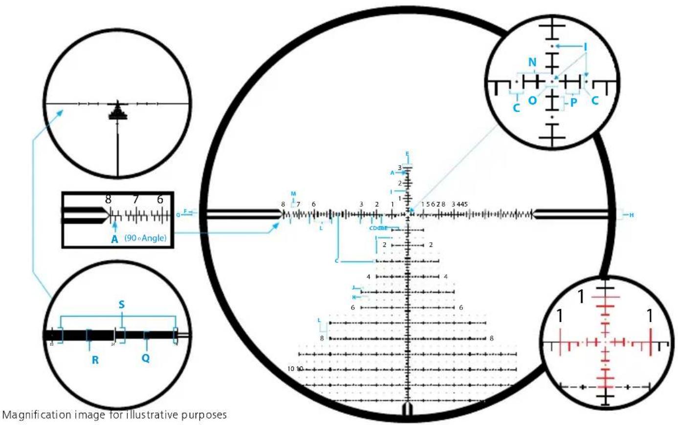
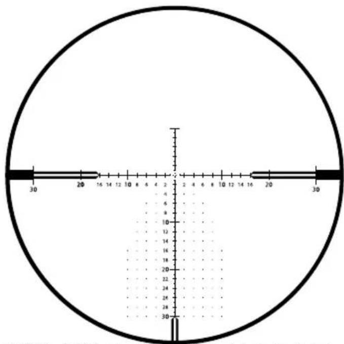
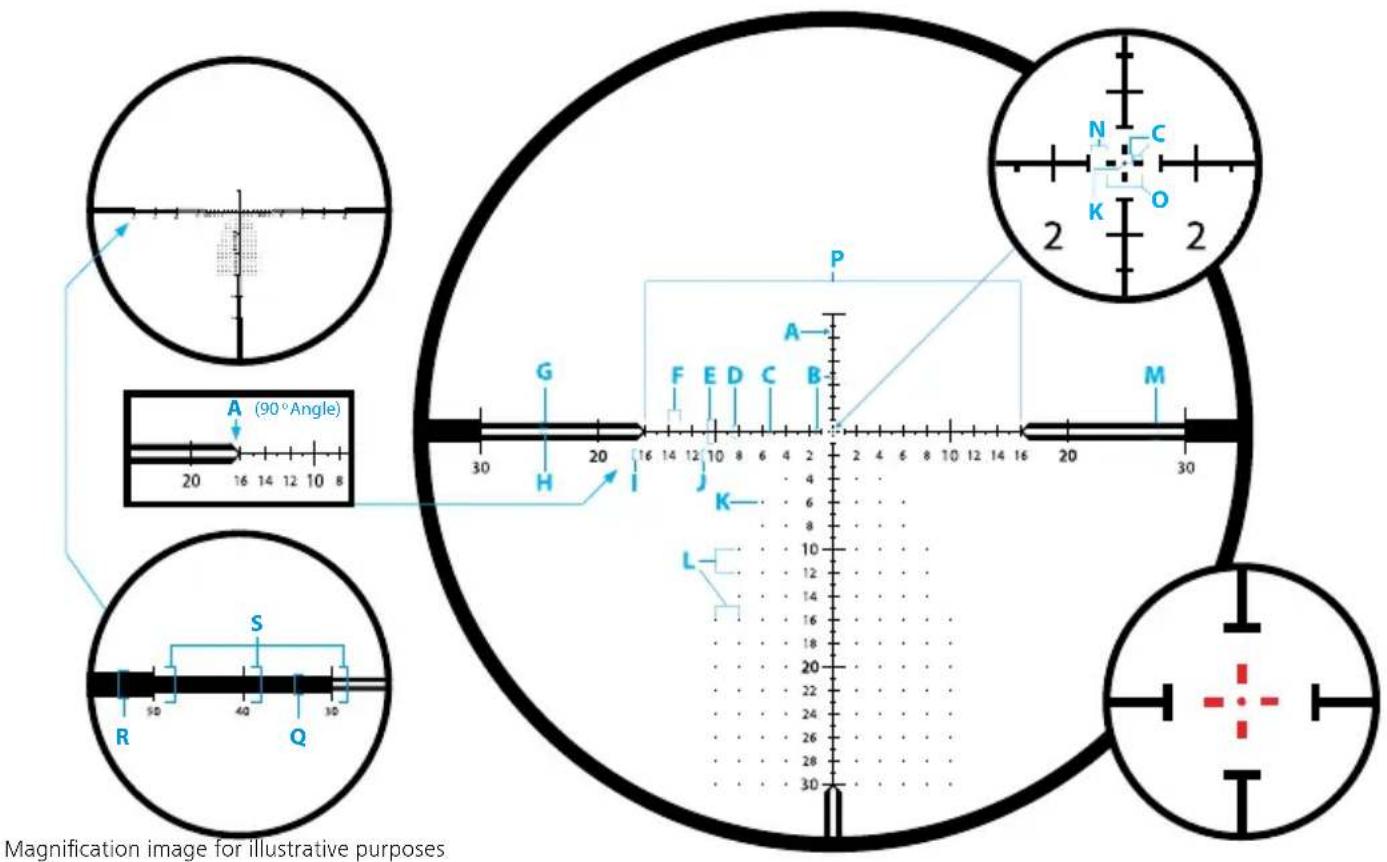
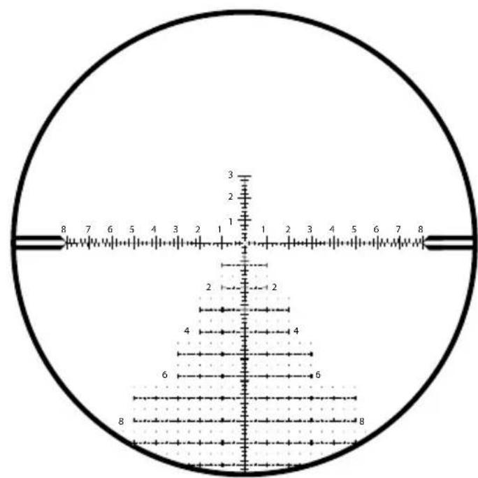
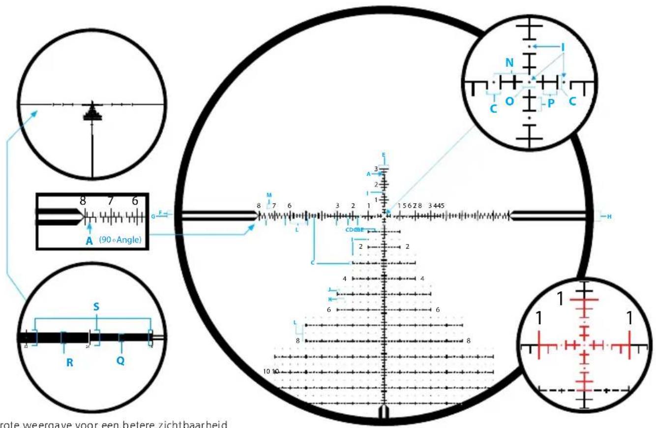
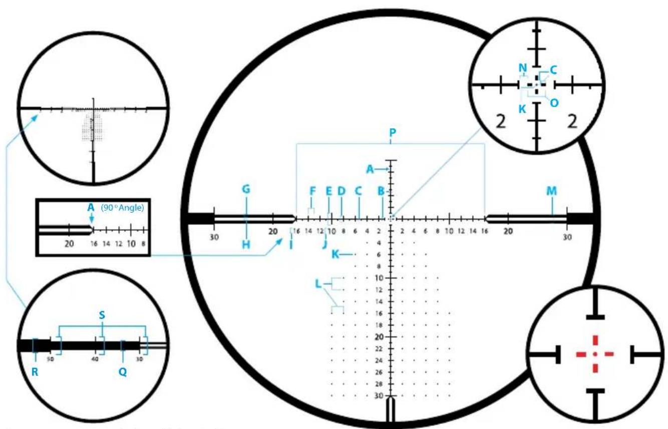
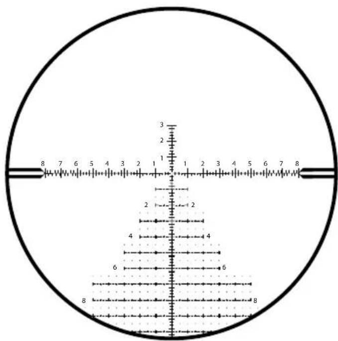
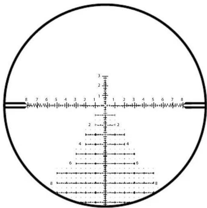
Reticle Type ZF-MRi (FFP)
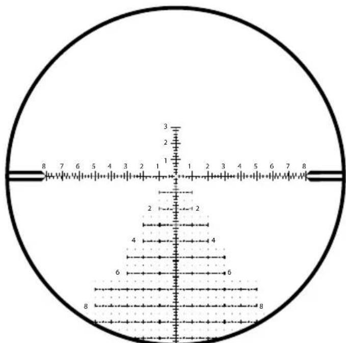
ZF-MRi = ZEISS First Focal Plane - Milliradian, illuminated
ZEISS LRP S3 425-50 636-56
| Unit of Measure MRAD | |
| Line Thickness A 0.03 | |
| Distance B 0.1 | |
| Distance C 0.2 | |
| Distance D 0.4 | |
| Distance E 0.6 | |
| Distance F 0.2 | |
| Distance G 0.2 | |
| Distance H 0.6 | |
| Dot Size I | 0.04 |
| Distance J | 0.2 |
| Distance K | 0.5 |
| Distance L | 1.0 |
| Standard Number Size M | 0.3 |
| Distance N | 0.5 |
| Distance O | 0.2 |
| Distance P | 0.2 |
| Distance Q | 0.9 |
| Distance R | 1.2 |
| Distance S | 1.8 |
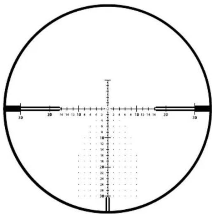
Reticle Type ZF-MOAi (FFP)
ZF-MOAi = ZEISS First Focal Plane - Minute of Angle, illuminated
ZEISS LRP S3 425-50 636-56
| Unit of Measure MOA | |
| Line Thickness A | 0.1 |
| Distance B | 0.5 |
| Distance C | 0.25 |
| Distance D | 1.0 |
| Distance E | 2.0 |
| Distance F | 1.0 |
| Distance G | 0.5 |
| Distance H | 0.5 |
| Standard Number Size I | 0.75 |
| 10, 20, 30 Number Size J | 1.0 |
| Dot Size K | 0.125 |
| Dot Spacing L 2.0 | |
| Distance M 1.5 | |
| Spacing around Center Cross N 0.5 | |
| Distance O 1.0 | |
| Distance P 32 | |
| Distance Q 2.0 | |
| Distance R 3.0 | |
| Distance S | 4.0 |
Accessories
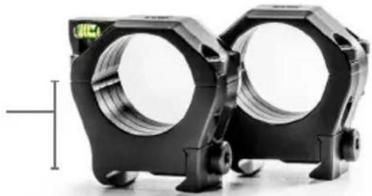
ZEISS Precision Rings with Integral Anti-cant Bubble Level
ZEISS ultralight 1913 Mil-Std, STANAG-compliant rings are manufactured to the highest of standards from premium materials and with tight tolerances for your long-term safety and field applications. They are designed for optimal long-range shooting solutions and allow for either right or left-handed operations as well as eye dominance. The bubble level is easily viewed from the shooting position, creating no disturbance in your shooting position. A smarter, sleeker, and ultralightweight ring design for all heavy-duty hunting and shooting applications.
Ring height measurements are determined from the top of the mounting rail to the center line of the ring's bore. 34 mm needed for ZEISS LRP S3
natural_image
Two black mechanical components with hexagonal bases and circular cutouts, no visible text or symbolsRecoil Lug
Integral bottom recoil lug for best alignment and a secure zero under the harshest recoil.
Hard Case
Included, with both T15 and T25 Torx ^® driver bits.
Bubble Level
Integral anti-cant bubble level in top half of ring.
Ultralight
Approximately 4.4 oz. with screws (set 30 mm low).
Durable Material
7075-T6 aluminum, 30-micron hard anodized finish – matte black.
Wider
Offers more clamping surface for a more secure mounting solution for heavy recoiling rifles and heavy riflescopes.
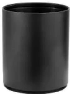
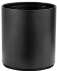
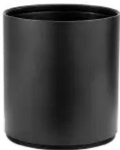
Sunshade 3"
Matte black – hard anodized sunshades.
This ZEISS accessory helps to eliminate harsh glare from the sun while viewing and shooting. Simply install by threading the sunshade to the riflescope's objective.
natural_image
Black cylindrical object with smooth surface and rounded edges (no text or symbols visible)Order no.
000000-2525-172
50 mm for LRP S3 425-50

natural_image
Black cylindrical object with smooth surface and rounded edges (no text or symbols visible)Order no.
000000-2525-173
56 mm for LRP S3 636-56
Care and Maintenance
Ensure your ZEISS riflescope is not exposed to extreme heat over prolonged periods of time, such as those elevated temperatures sometimes found inside of a vehicle on a sunny day.
Your ZEISS riflescope is designed and manufactured to give you many years of reliable and long-term service. One of the best ways to protect your optical investment is to be sure and use appropriate lens covers when you are not using your riflescope. To further protect your riflescope, ZEISS strongly suggests you keep the product clean and free of troublesome sand, dirt, saltwater, and various contaminants.
Cleaning Your ZEISS Riflescope's Exterior
For a heavily soiled riflescope, you can rinse the riflescope under a stream of lukewarm water and then wipe it down with a soft, clean tissue. Do not use strong solvents to clean your riflescope or its optics. Using such solvents will void the ZEISS warranty.
ZEISS LotuTec® Coating
Your riflescope has ZEISS LotuTec ^® coating. The effective protective coating for the lens surfaces noticeably reduces contamination of the lenses through an especially smooth surface and the resulting water-beading effect. All types of contamination stick less and can be quickly and easily removed without smearing. LotuTec ^® coating is durable and abrasion-resistant.

Cleaning Your Lenses
ZEISS recommends using original ZEISS lens cleaning solutions to care for the lenses on your riflescope.
Long-Term Storage
ZEISS suggests you remove the battery – where applicable – if the riflescope will not be used for a prolonged period of time. Store the riflescope in a cool, dry, clean, and contaminant-free location.
EN Instructions for use ZEISS LRP S3 425-50 | 636-56
Customer Service and Warranty

For service questions or obtaining the warranty terms, please see our website: www.zeiss.com/cop/warranty
For service inquiry or a free copy of the warranty terms for your region, please contact:
ZEISS Customer Service
Carl Zeiss Sports Optics GmbH
Gloelstr. 3 – 5, 35576 Wetzlar, Germany
Phone +49 800 934 77 33
E-Mail consumerproducts@zeiss.com
ZEISS Customer Service USA
Carl Zeiss SBE, LLC
Consumer Products
1050 Worldwide Blvd.
Hebron, KY 41048-8632, USA
Phone 1-800-441-3005
E-Mail info.sportsoptics.us@zeiss.com
www.zeiss.com/cop/safety

Inhaltsverzeichnis
www.zeiss.com/precision-shooting

natural_image
Close-up of a black mechanical device with labeled gears (R1, R2, G1, G2) and a 10-meter scale indicator, showing rotational motion (no text beyond labels)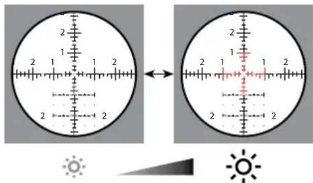
natural_image
Close-up of a black mechanical component with blue circular arrows indicating rotation or adjustment (no text or symbols)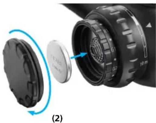
natural_image
Close-up of a camera lens assembly showing internal components and a blue circular arrow indicating rotation (no text or symbols)Parallaxeeinstellung
natural_image
Diagram of a mechanical component with a pointed tip and internal shaft, no text or symbols present(3)

natural_image
Diagram of a mechanical component with a blue arrow indicating direction, no text or symbols presentnatural_image
Two black mechanical components with circular openings, no visible text or symbolsRückstoßstollen
natural_image
Black cylindrical object with smooth surface and no visible text or symbolsnatural_image
Black cylindrical object with smooth surface and rounded edges (no text or symbols visible)1050 Worldwide Blvd.
Hebron, KY 41048-8632, USA
Telefon 1-800-441-3005
E-Mail info.sportsoptics.us@zeiss.com
www.zeiss.com/precision-shooting

natural_image
Two circular diagrams showing a landscape with mountains and a crosshairs, one with a scale bar and arrow, the other with a shaded region (no text or symbols)(1a) Grossissement min.
(1b) Grossissement max.
natural_image
Close-up of a black mechanical device with labeled gears (R1, R2, G1, G2) and a 10-meter scale indicator, showing rotational motion (no text beyond labels)
natural_image
Close-up of a black mechanical component with blue circular arrows indicating rotation or adjustment (no text or symbols)
natural_image
Close-up of a camera lens assembly showing internal components and a blue circular arrow indicating rotation (no text or symbols)natural_image
Diagram of a mechanical component with a pointed tip and internal shaft, no text or symbols presentnatural_image
Two circular diagrams with concentric rings and crosshairs, labeled (2) and (3), no text or symbols present.natural_image
Diagram of a mechanical component with a highlighted section and directional arrows (no text or symbols)Réticule ZF-MRi (FFP)

ZF-MRi = ZEISS First Focal Plane - Milliradian, illuminated ZEISS premier plan focal - milliradian, éclairé
ZEISS LRP S3 425-50 636-56
natural_image
Two black mechanical components with hexagonal bases and circular cutouts, shown side by side (no text or symbols visible)Cale anti-recul
natural_image
Black cylindrical object with smooth surface and no visible text or symbolsnatural_image
Black cylindrical object with a hollow top, resembling a cup or container (no text or symbols visible)1050 Worldwide Blvd.
www.zeiss.com/precision-shooting

12-Torreta de ajuste lateral MOA
natural_image
Two circular diagrams showing a landscape with mountains and a crosshair overlay, no text or symbols present.(2a) Reticula no enfocada (2b) Retícula enfocada
natural_image
Close-up of a black mechanical device with labeled gears (R1, R2, G1, G2) and a 10-meter scale indicator, showing no readable text or symbols beyond labels.
natural_image
Close-up of a black mechanical component with blue circular arrows indicating rotation or adjustment (no text or symbols)
natural_image
Close-up of a camera lens assembly showing internal components and a blue circular arrow indicating rotation (no text or symbols)Ajuste del paralaje
natural_image
Diagram of a mechanical component with a pointed tip and internal shaft (no text or symbols)natural_image
Two circular diagrams with concentric rings and crosshairs, labeled (2) and (3), no text or symbols present.(3)
(3) (4) Torreta de ajuste lateral MRAD
Torreta de ajuste lateral MOA

natural_image
Diagram of a mechanical component with rotational arrows indicating motion (no text or symbols)natural_image
Diagram of a mechanical component with a highlighted section and directional arrows (no text or symbols)natural_image
Two black mechanical components with hexagonal bases and circular cutouts, shown against a white background (no text or symbols visible)Túnel de retroceso
natural_image
Black cylindrical object with smooth surface and no visible text or symbolsnatural_image
Black cylindrical object with smooth surface and narrow neck (no text or symbols visible)1050 Worldwide Blvd.
Hebron, KY 41048-8632, EE. UU.
www.zeiss.com/cop/safety

Indice
www.zeiss.com/precision-shooting

natural_image
Close-up of a black brake shift lever with labeled segments (R1, R2, G1, G2) and a 10-meter scale indicator (no text beyond labels)
www.zeiss.com/cop/safety
natural_image
Close-up of a black mechanical component with blue circular arrows indicating rotation or adjustment (no text or symbols)
natural_image
Close-up of a camera lens assembly showing internal components and a blue circular arrow indicating rotation (no text or symbols)(2)
natural_image
Diagram of a mechanical component with a pointed tip and internal shaft, no text or symbols presentnatural_image
Two circular diagrams with concentric rings and crosshairs, labeled (2) and (3), no text or symbols present.natural_image
Diagram of a mechanical component with a highlighted shaft and directional arrows indicating motion (no text or symbols)Reticolo ZF-MRi (FFP)

ZF-MRi = ZEISS First Focal Plane - Milliradian, illuminated ZEISS reticolo sul primo piano focale - milliradiani, illuminato
ZEISS LRP S3 425-50 636-56
natural_image
Black cylindrical object with smooth surface and rounded edges (no text or symbols visible)N. d'ordine
000000-2525-172
50 mm per LRP S3 425-50
natural_image
Black cylindrical object with smooth surface, no visible text or symbolsN. d'ordine
000000-2525-173
56 mm per LRP S3 636-56
Cura e manutenzione
1050 Worldwide Blvd.
Hebron, KY 41048-8632, USA
Telefono 1-800-441-3005
E-mail info.sportsoptics.us@zeiss.com
www.zeiss.com/cop/safety

Inhoudsopgave
www.zeiss.com/precision-shooting

natural_image
Two circular diagrams showing a landscape with mountains and a crosshairs, one with a scale bar and arrow, the other with a shaded region (no text or symbols)(1a) Lage vergroting
(1b) Hoge vergroting

natural_image
Close-up of a black brake shift lever with labeled segments (R1, R2, G1, G2) and a 10-meter scale indicator (no text beyond labels)
Verlichtingstechnologie
natural_image
Close-up of a black mechanical component with blue circular arrows indicating rotation or adjustment (no text or symbols)
natural_image
Close-up of a camera lens assembly showing internal components and a blue circular arrow indicating rotation (no text or symbols)Parallaxregeling
natural_image
Diagram of a mechanical component with a pointed tip and shaft, showing internal structure (no text or symbols)natural_image
Two circular diagrams with concentric rings and crosshairs, labeled (2) and (3), no text or symbols present.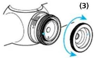
natural_image
Diagram of a mechanical component with rotational motion arrows, no text or symbols presentnatural_image
Diagram of a mechanical component with a blue arrow indicating direction, labeled (6) (no text or symbols on the diagram itself)Vizier ZF-MRi (FFP)
ZF-MRi = ZEISS First Focal Plane - Milliradian, illuminated ZEISS vizier in eerste beeldvlak - mil, verlicht
ZEISS LRP S3 425-50 636-56
| Maateenheid MRAD | |
| Lijndikte A 0,03 | |
| Afstand B 0,1 | |
| Afstand C 0,2 | |
| Afstand D 0,4 | |
| Afstand E 0,6 | |
| Afstand F 0,2 | |
| Afstand G 0,2 | |
| Afstand H 0,6 | |
| Puntgrootte I | 0,04 |
| Afstand J | 0,2 |
| Afstand K | 0,5 |
| Afstand L | 1,0 |
| Standaard cijfergrootte M | 0,3 |
| Afstand N | 0,5 |
| Afstand O | 0,2 |
| Afstand P | 0,2 |
| Afstand Q | 0,9 |
| Afstand R | 1,2 |
| Afstand S | 1,8 |
Vizier ZF-MOAi (FFP)
ZF-MOAi = ZEISS First Focal Plane – Minute of Angle, illuminated ZEISS vizier in eerste beeldvlak – boogminuten verlicht
ZEISS LRP S3 425-50 636-56
| Maateenheid MOA | |
| Lijndikte A | 0,1 |
| Afstand B | 0,5 |
| Afstand C | 0,25 |
| Afstand D | 1,0 |
| Afstand E | 2,0 |
| Afstand F | 1,0 |
| Afstand G | 0,5 |
| Afstand H | 0,5 |
| Standaard cijfergrootte I | 0,75 |
| 10, 20, 30 cijfergrootte J | 1,0 |
| Puntgrootte K | 0,125 |
| Puntafstand L 2,0 | |
| Afstand M 1,5 | |
| Afstand rond middenkruis N 0,5 | |
| Afstand O 1,0 | |
| Afstand P 32 | |
| Afstand Q 2,0 | |
| Afstand R 3,0 | |
| Afstand S | 4,0 |
natural_image
Two black mechanical components with circular cutouts, shown against a white background (no text or symbols visible)Terugslagnok
natural_image
Black cylindrical object with smooth surface and rounded edges (no text or symbols visible)Bestelnr.
000000-2525-172
natural_image
Black cylindrical object with smooth surface and rounded edges (no text or symbols)Bestelnr.
000000-2525-173
1050 Worldwide Blvd.
Hebron, KY 41048-8632, USA
Telefoon 1-800-441-3005
E-mail info.sportsoptics.us@zeiss.com
www.zeiss.com/cop/safety

Indholdsfortegnelse
www.zeiss.com/precision-shooting

12-Sidejusteringstårn MOA

ADVARSEL!
natural_image
Two circular diagrams showing a landscape with mountains and a crosshair overlay, no text or symbols present.natural_image
Close-up of a black mechanical device with labeled gears (R1, R2, G1, G2) and a 10-meter scale indicator, showing no readable text or symbols beyond labels.
Belysningsteknologi
www.zeiss.com/cop/safety.

natural_image
Close-up of a black mechanical component with blue circular arrows indicating rotation or adjustment (no text or symbols)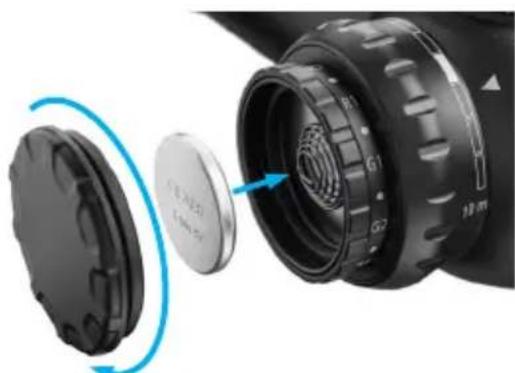
natural_image
Close-up of a camera lens assembly showing internal components and a blue circular arrow indicating rotation (no text or symbols)(2)
Parallakseindstilling
Billedplan bag ved trådkorset (parallakse)
natural_image
Diagram of a mechanical component with a pointed tip and internal shaft, no text or symbols presentnatural_image
Two circular diagrams with concentric rings and crosshairs, labeled (2) and (3), no text or symbols present.natural_image
Diagram of a mechanical component with rotational motion arrows, no text or symbols presentnatural_image
Diagram of a mechanical component with a circular housing and directional arrows indicating motion (no text or symbols)Trådkors ZF-MRi (FFP)

ZF-MRi = ZEISS First Focal Plane – Milliradian, illuminated ZEISS trådkors på det første billedniveau – milliradian, belyst
ZEISS LRP S3 425-50 636-56
natural_image
Black cylindrical object with smooth surface, no visible text or symbolsBest.-nr.
000000-2525-172
50 mm til LRP S3 425-50

natural_image
Black cylindrical object with smooth surface and narrow neck (no text or symbols)Best.-nr.
000000-2525-173
56 mm til LRP S3 636-56
1050 Worldwide Blvd.
Hebron, KY 41048-8632, USA
Telefon 1-800-441-3005
E-mail info.sportsoptics.us@zeiss.com
www.zeiss.com/cop/safety

Sisällysluettelo
www.zeiss.com/precision-shooting

natural_image
Close-up of a black brake shift lever with labeled segments (R1, R2, G1, G2) and a 10-meter scale indicator (no text beyond labels)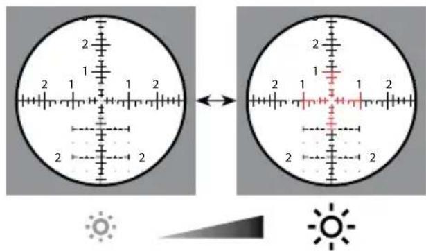
Valaistusteknologia
natural_image
Close-up of a black mechanical component with blue circular arrows indicating rotation or adjustment (no text or symbols visible)
natural_image
Close-up of a camera lens assembly showing internal components and a blue circular arrow indicating rotation (no text or symbols)Parallaksisäätö
natural_image
Diagram of a mechanical component with a pointed tip and internal shaft, no text or symbols presentnatural_image
Two circular diagrams with concentric rings and crosshairs, labeled (2) (3), no text or symbols present.(3)
natural_image
Close-up of two analog caliper scales showing main scale and dial (no text or symbols visible)natural_image
Diagram of a mechanical component with rotational motion arrows, no text or symbols presentnatural_image
Diagram of a mechanical component with a circular component and directional arrows indicating motion (no text or symbols)Ristikko ZF-MRi (FFP)
Ristikko ZF-MOAi (FFP)

natural_image
Black cylindrical object with smooth surface and no visible text or symbolsTilausnro
000000-2525-172
50 mm LRP S3 425-50:lle
natural_image
Black cylindrical object with smooth surface and rounded edges (no text or symbols visible)Tilausnro
000000-2525-173
56 mm LRP S3 636-56:lle
Hoito ja huolto
1050 Worldwide Blvd.
Hebron, KY 41048-8632, USA
Puhelin 1-800-441-3005
Sähköposti info.sportsoptics.us@zeiss.com
www.zeiss.com/precision-shooting

natural_image
Two circular diagrams showing a landscape with mountains and a crosshair overlay, no text or symbols present.natural_image
Close-up of a black brake shift lever with labeled segments (R1, R2, G1, G2) and a 10-meter scale indicator (no text beyond labels)
natural_image
Close-up of a black mechanical component with blue circular arrows indicating rotation or adjustment (no text or symbols visible)
natural_image
Close-up of a camera lens assembly showing internal components and a blue circular arrow indicating rotation (no text or symbols)Parallaxisbeállítás
natural_image
Diagram of a mechanical component with a pointed tip and internal shaft, no text or symbols presentnatural_image
Abstract geometric diagram with concentric circles and intersecting lines, no text or symbols present
natural_image
Concentric circle with concentric rings and crosshairs, no text or symbols present(3)

natural_image
Diagram of a mechanical component with a highlighted section and directional arrows (no text or symbols)natural_image
Two black mechanical components with hexagonal bases, no visible text or symbolsVisszarúgás-elnyelő
natural_image
Black cylindrical object with smooth surface and no visible text or symbolsCikkszám
000000-2525-172
natural_image
Black cylindrical object with smooth surface and narrow neck (no text or symbols visible)Cikkszám
000000-2525-173
1050 Worldwide Blvd.
Hebron, KY 41048-8632, USA
Telefon 1-800-441-3005
E-mail info.sportsoptics.us@zeiss.com
www.zeiss.com/cop/safety

Spis treści
www.zeiss.com/precision-shooting

natural_image
Two circular diagrams showing a landscape with mountains and a crosshair overlay, no text or symbols present.natural_image
Close-up of a black brake shift lever with labeled segments (R1, R2, G1, G2) and a 10-meter scale indicator (no text beyond labels)
natural_image
Close-up of a black mechanical component with blue circular arrows indicating rotation or adjustment (no text or symbols)
natural_image
Close-up of a camera lens assembly showing internal components and a blue circular arrow indicating rotation (no text or symbols)natural_image
Diagram of a mechanical component with a pointed tip and dashed centerline, no text or symbols presentnatural_image
Two circular diagrams with concentric rings and crosshairs, labeled (2) (3), no text or symbols present.(3)
natural_image
Diagram of a mechanical component with a circular housing and directional arrows indicating motion (no text or symbols)natural_image
Two black mechanical components with hexagonal bases, no visible text or symbolsOpora (recoil lug)
natural_image
Black cylindrical object with smooth surface and rounded edges (no text or symbols visible)Nr katalogowy
000000-2525-172
natural_image
Black cylindrical object with rounded edges, resembling a cup or container (no text or symbols visible)Nr katalogowy
000000-2525-173
1050 Worldwide Blvd.
Hebron, KY 41048-8632, USA
Telefon 1-800-441-3005
E-mail info.sportsoptics.us@zeiss.com
Bruksanvisningar ZEISS LRP S3
425-50 | 636-56
Patent: www.zeiss.com/cop/patents
EN DE FR ES IT NL DK
FI HU PL SE RU JP CN | 06.2022

www.zeiss.com/cop/safety

www.zeiss.com/precision-shooting

natural_image
Two circular diagrams showing a landscape with mountains and a crosshair overlay, no text or symbols present.natural_image
Close-up of a black brake shift lever with labeled segments (R1, R2, G1, G2) and a 10-meter scale indicator (no text beyond labels)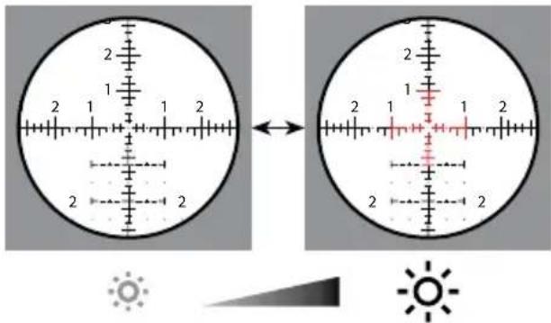
Belysningsteknik
natural_image
Close-up of a black mechanical component with blue circular arrows indicating rotation or adjustment (no text or symbols)
natural_image
Close-up of a camera lens assembly showing internal components and a blue circular arrow indicating rotation (no text or symbols)Parallaxinställning
Fokalplan bakom streckplattan (parallax)

natural_image
Diagram of a mechanical component with a pointed tip and internal shaft, no text or symbols presentnatural_image
Two circular diagrams with concentric rings and crosshairs, labeled (2) and (3), no text or symbols present.natural_image
Diagram of a mechanical component with a highlighted section and directional arrows (no text or symbols)Streckplatta ZF-MRi (FFP)
natural_image
Black cylindrical object with smooth surface and rounded edges (no text or symbols visible)natural_image
Black cylindrical object with smooth surface and rounded edges (no text or symbols)1050 Worldwide Blvd.
Hebron, KY 41048-8632, USA
Telefon 1-800-441-3005
E-post info.sportsoptics.us@zeiss.com
www.zeiss.com/cop/safety

Содержание
natural_image
Close-up of a black brake shift lever with labeled segments (R1, R2, G1, G2) and a 10-meter scale indicator (no text beyond labels)
natural_image
Close-up of a black mechanical component with blue circular arrows indicating rotation or adjustment (no text or symbols)
natural_image
Close-up of a camera lens assembly showing internal components and a blue circular arrow indicating rotation (no text or symbols)natural_image
Diagram of a mechanical component with a pointed tip and shaft, showing internal structure (no text or symbols)natural_image
Abstract geometric diagram with concentric circles and intersecting lines, no text or symbols present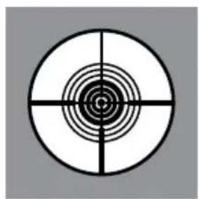
natural_image
Concentric circle with concentric rings and crosshairs, no text or symbols present(3)
natural_image
Diagram of a mechanical component with two circular parts and directional arrows indicating rotation (no text or symbols)natural_image
Diagram of a mechanical component with a blue arrow indicating direction, no text or symbols presentnatural_image
Two black mechanical components with hexagonal bases, no visible text or symbolsШептало отдачи
natural_image
Black cylindrical object with smooth surface and rounded edges (no text or symbols visible)natural_image
Black cylindrical object with rounded edges, resembling a cup or container (no text or symbols visible)1050 Worldwide Blvd.
www.zeiss.com/precision-shooting
natural_image
Two circular diagrams showing a landscape with mountains and a crosshair overlay, no text or symbols present.(1a) 低倍率
(1b) 高倍率
natural_image
Close-up of a black mechanical device with labeled gears (R1, R2, G1, G2) and a 10-meter scale indicator, showing rotational motion (no text beyond labels)
照明技術
natural_image
Close-up of a black mechanical component with blue circular arrows indicating rotation or adjustment (no text or symbols)
natural_image
Close-up of a camera lens assembly showing internal components and a blue circular arrow indicating rotation (no text or symbols)パララックス調整
natural_image
Diagram of a mechanical component with a pointed tip and shaft, showing internal structure (no text or symbols)natural_image
Two circular diagrams with concentric rings and crosshairs, labeled (2) and (3), no text or symbols present.(3)
natural_image
Diagram of a mechanical component with a circular component and directional arrows indicating motion (no text or symbols)レチクル ZF-MRi (FFP)

natural_image
Black cylindrical object with smooth surface and no visible text or symbolsnatural_image
Black cylindrical object with smooth surface and rounded edges (no text or symbols visible)1050 Worldwide Blvd.
Hebron, KY 41048-8632, USA
電話 1-800-441-3005
www.zeiss.com/cop/safety

目录
www.zeiss.com/precision-shooting

H1- 高度调节轮 MRAD
H2-高度调节轮MOA
I1-侧向调节轮MRAD
12-侧向调节轮MOA
natural_image
Diagram showing a crosshair view of a landscape with mountains and a scale bar, alongside a magnified circular view of a landscape with a scale bar (no text or symbols)natural_image
Close-up of a black mechanical device with labeled gears (R1, R2, G1, G2) and a 10-meter scale indicator, showing rotational motion (no text beyond labels)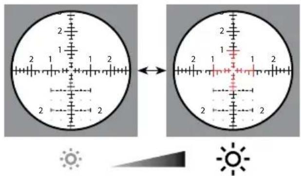
照明技术
natural_image
Close-up of a black mechanical component with blue circular arrows indicating rotation or adjustment (no text or symbols)
natural_image
Close-up of a camera lens assembly showing internal components and a blue circular arrow indicating rotation (no text or symbols)(2)
视差调节
瞄准装置后方的焦平面 (视差)
图像和瞄准装置位于一个平面上(无视差)

警告!
natural_image
Diagram of a mechanical component with an eye and shaft, no text or symbols presentnatural_image
Two circular diagrams with concentric rings and crosshairs, labeled (2) and (3), no text or symbols present.(3)
MRAD 高度调节轮

MOA 高度调节轮
(3) (4)
MOA 侧向调节轮
natural_image
Diagram of a mechanical component with rotational motion arrows, no text or symbols presentnatural_image
Diagram of a mechanical component with a highlighted shaft and directional arrows indicating motion (no text or symbols)瞄准装置 ZF-MRi (FFP)

ZF-MRi = ZEISS First Focal Plane - Milliradian, illuminated ZEISS 瞄准装置处于第一焦平面-毫弧度,发光
ZEISS LRP S3 425-50 636-56
natural_image
Black cylindrical object with smooth surface and no visible text or symbolsnatural_image
Black cylindrical object with smooth surface and rounded edges (no text or symbols visible)1050 Worldwide Blvd.
Hebron, KY 41048-8632, USA
电话 1-800-441-3005
电子邮箱 info.sportsoptics.us@zeiss.com
Carl Zeiss AG
Consumer Products
Carl-Zeiss-Strasse 22
73447 Oberkochen
Germany
www.zeiss.com/consumer-products
EN_2424-945 000000-2526-068 CZ-06/2022 Subject to change in design and scope of delivery and as a result of ongoing technical development. ZEISS is not responsible for typographical errors. Product images are for illustration purposes only. Specifications and products may change without prior written notice.
- Long-Range Precision Riflescope
- WARNING!
- Scope of supply
- Description of the Components
- Changing the Magnification
- Focusing the Reticle / Diopter Adjustment
- Reticle Illumination
- Illumination technology
- Battery Replacement
- Inserting/removing the battery
- Parallax Adjustment
- Adjusting to Remove Parallax
- Basic Mounting InstructionsWARNIN
- Ring and Base Selection (Rings Equal 34 mm)
- Mounting the Base to the Action
- Mounting the Rings to the Base
- Mounting the Riflescope
- Leveling The Reticle
- Establishing a Sight-In Zero
- Elevation Turret
- How to Set the Ballistic Stop, Elevation
- Attention: Before attempting to zero your rifle, always make sure the firearm is unloaded.
- Step 2:
- External Locking Windage Turret (ELWT)
- How to Re-Index to Zero (ELWT)
- Accessories
- ZEISS Precision Rings with Integral Anti-cant Bubble Level
- Recoil Lug
- Hard Case
- Bubble Level
- Ultralight
- Durable Material
- Wider
- Sunshade 3"
- Care and Maintenance
- Cleaning Your ZEISS Riflescope's Exterior
- ZEISS LotuTec® Coating
- Cleaning Your Lenses
- Long-Term Storage
- Customer Service and Warranty
- ZEISS Customer Service
- ZEISS Customer Service USA
- Parallaxeeinstellung
- Rückstoßstollen
- Cale anti-recul
- Ajuste del paralaje
- Túnel de retroceso
- Cura e manutenzione
- Verlichtingstechnologie
- Parallaxregeling
- Terugslagnok
- ADVARSEL!
- Belysningsteknologi
- Parallakseindstilling
- Valaistusteknologia
- Parallaksisäätö
- Hoito ja huolto
- Parallaxisbeállítás
- Visszarúgás-elnyelő
- Opora (recoil lug)
- Bruksanvisningar ZEISS LRP S3
- Belysningsteknik
- Parallaxinställning
- Шептало отдачи
- 照明技術
- パララックス調整
- 照明技术
- 视差调节
- 警告!
- Carl Zeiss AG
Brand : ZEISS
Model : LRP S3 6-36x56
Category : Riflescope