Pro Serie Wifi - Air Conditioning TAURUS - Free user manual and instructions
Find the device manual for free Pro Serie Wifi TAURUS in PDF.

User questions about Pro Serie Wifi TAURUS
0 question about this device. Answer the ones you know or ask your own.
Ask a new question about this device
Download the instructions for your Air Conditioning in PDF format for free! Find your manual Pro Serie Wifi - TAURUS and take your electronic device back in hand. On this page are published all the documents necessary for the use of your device. Pro Serie Wifi by TAURUS.
USER MANUAL Pro Serie Wifi TAURUS
natural_image
Line drawing of a rectangular air conditioner unit with ventilation grilles (no text or symbols)ES. MANUAL DE INSTRUCCIONES
EN. OPERATING MANUAL
FR. NOTICE D'UTILISATION
| TIPO DE INVERSOR MODELO capacidad (Btu/h) | 9k 12k | 18k | 24k | ||
| área seccional | |||||
| Cable de alimentación | N | 1.5mm^2 | 1.5mm^2 | 1.5mm^2 | 2.5mm^2 |
| L | 1.5mm^2 | 1.5mm^2 | 1.5mm^2 | 2.5mm^2 | |
| ⊕ | 1.5mm^2 | 1.5mm^2 | 1.5mm^2 | 2.5mm^2 | |
| Cable de conexión | N | 0.75mm^2 | 0.75mm^2 | 0.75mm^2 | 0.75mm^2 |
| L o (L) | 0.75mm^2 | 0.75mm^2 | 0.75mm^2 | 0.75mm^2 | |
| 1 | 0.75mm^2 | 0.75mm^2 | 0.75mm^2 | 0.75mm^2 | |
| ⊕ | 0.75mm^2 | 0.75mm^2 | 0.75mm^2 | 0.75mm^2 | |
NOTA:
natural_image
Diagram of a coiled tube with two connectors and directional arrows indicating rotation (no text or symbols)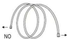
natural_image
Diagram of a coiled tube with directional arrows indicating flow or movement (no text or symbols)natural_image
Four sequential diagrams showing a mechanical or electrical component with arrows indicating movement, no text or symbols present.PASO 6: CONECTAR EL CABLEADO
natural_image
Pure diagram of a pipe or tube with a circular symbol and a small object inside, no text or labels present.natural_image
Line drawing of a dual air conditioner unit with fan blades and ventilation slots (no text or symbols)PANTALLA DEL MANDO A DISTANCIA
Many thanks for choosing to purchase a TAURUS brand product.
Thanks to its technology, design and operation and the fact that it exceeds the strictest quality standards, a fully satisfactory use and long product life can be assured.
SAFETY ADVICE AND WARNINGS

Please read this manual thoroughly. Keep this instructions manual for future reference.

Do not use your air conditioner before you have carefully read the operating instructions of the appliance.
Do not install the single split air conditioner before reading carefully the technical installation instructions. Failure to follow
and observe these instructions could lead to an accident.

CAUTION: RISK OF FIRE.
This appliance contains flammable refrigerant R32.
- WARNING: Do not use means to accelerate the defrosting process or to clean, other than those recommended by the manufacturer.
- The appliance shall be stored in a room without continuously operating ignition sources (for example: open flames, an operating gas appliance or an operating electric heater).
- Do not pierce or burn.
- Be aware that refrigerants may not contain an odour.
- The appliance shall be installed, operated and stored in a room with a floor area larger than 4m^2 .
- The installation, maintenance, servicing, reparation, or leak checks shall only be made by professional, qualified persons trained and certified on safe handling of fluorinated greenhouse gases in accordance to EU regulation 517/2014 or 2024/573 and national laws.
- This appliance can be used by children aged from 8 years and above and persons with reduced physical, sensory or mental capabilities or lack of experience and knowledge if they have been given supervision or instruction concerning use of the appliance in a safe way and understand the hazards involved.
- Cleaning and user maintenance shall not be made by children.
- Children should be supervised to ensure that they do not play with the appliance.
- This appliance must be fitted with means for disconnection from the supply mains having a contact
separation in all poles that provide full disconnection under over voltage category III conditions, and these means for disconnection must be incorporated in the fixed wiring in accordance with the wiring rules.
- If the supply cord is damaged, it must be replaced by the manufacturer, its service agent or similarly qualified persons in order to avoid a hazard.
- This appliance shall be installed in accordance with national wiring regulations.
- The fuse used in the indoor unit is type: 50T or type: 50CT or type: 524, with electrical characteristics: 250VAC, T4 A, 6*21,5 mm.
- The fuse used in the outdoor unit is type: 50CF or type:524, with electrical characteristics: 250VAC, 15 A, 5,5^*21 mm.
- WARNING: To reduce the risk of fire, keep textiles, curtains, or any other flammable material a minimum distance of 1 m from the air outlet.
- Do not install this appliance at a distance of less than 1 m from flammable substances (alcohol, etc.) Or from pressurized containers (e.g. spray cans).
- This appliance has been made for air conditioning domestic environments and must not be used for any other purpose, such as for drying clothes, cooling food, etc.
- Always use the appliance with the air filter mounted. The use of the conditioner without air filter could cause an excessive accumulation of dust or waste on the inner parts of the device with possible subsequent failures.
- Never remain directly exposed to the flow of cold air for a long time. The direct and prolonged exposition to cold air could be dangerous for your health. Particular care should be taken in the rooms where there are children, old or sick people.
- Selecting the most suitable temperature can prevent damage to the appliance.
• The airflow direction must be properly adjusted. - The flaps must be directed downwards in the heating mode and upwards in the cooling mode.
- The packaging materials are recyclable and should be disposed of in separate waste bins according to the regulations of your community.
- The batteries in remote controller must be recycled or disposed of properly. Disposal of Scrap Batteries. Please discard the batteries as sorted municipal waste at the accessible collection point.
- For proper waste management, when the air conditioner is at the end of its useful life, ask a professional qualified person to uninstall safely the appliance, to ensure the proper collection, treatment, recovery, environmentally sound disposal, recycling, reclamation or destruction of fluorinated greenhouse gases contained in the appliance. Then take the air conditioner to a special waste collection center for disposal of waste of electrical and electronic equipment (WEEE).
- Only use the air conditioner as instructed in this booklet. These instructions are not intended to cover every possible condition and situation. As with any electrical household appliance, common sense and caution are therefore always recommended for installation, operation, and maintenance.
- If the appliance gives off smoke or there is a smell of burning, immediately cut off the power supply and contact the Service Center. The prolonged use of the device in such conditions could cause fire or electrocution.
- Have repairs carried out only by an authorized Service Center of the manufacturer. Incorrect repair could expose the user to the risk of electric shock.
- Unhook the automatic switch if you foresee not to use the device for a long time.
- Ensure that the appliance is disconnected from the power supply when it will remain inoperative for a long period and before carrying out any cleaning or maintenance.
- Do not bend, tug or compress the power cord since this could damage it. Electrical shocks or fire are probably due to a damaged power cord. Specialized technical personnel only must replace a damaged power cord.
-
Do not use extensions or gang modules.
-
Do not touch the appliance when barefoot or parts of the body are wet or damp.
- Do not obstruct the air inlet or outlet of the indoor or the outdoor unit. The obstruction of these openings causes a reduction in the operative efficiency of the conditioner with possible consequent failures or damages.
• In no way alter the characteristics of the appliance. - Do not install the appliance in environments where the air could contain gas, oil or sulphur or near sources of heat.
- Do not place any heavy or hot objects on top of the appliance.
- Do not leave windows or doors open for long when the air conditioner is operating.
- Do not direct the airflow onto plants or animals.
- A long direct exposition to the flow of cold air of the conditioner could have negative effects on plants and animals.
- Do not put the conditioner in contact with water. The electrical insulation could be damaged and thus causing electrocution.
- Do not climb onto or place any objects on the outdoor unit.
- Never insert a stick or similar object into the appliance. It could cause injury.
SERVICE INSTRUCTIONS (R32) WARNINGS
- Check the information in this manual to find out the dimensions of space needed for proper installation of the device, including the minimum distances allowed compared to adjacent structures.
- Appliance shall be installed, operated and stored in a room with a floor area larger than 4m^2 .
- The installation of pipe-work shall be kept to a minimum.
- The pipe-work shall be protected from physical damage, and shall not be installed in an unventilated space if the space is smaller than 4m^2 .
• The compliance with national gas regulations shall be observed. - The mechanical connections shall be accessible for maintenance purposes.
- Follow the instructions given in this manual for handling, installing, cleaning, maintaining and disposing of the refrigerant.
- Make sure ventilation openings clear of obstruction.
Notice: The servicing shall be performed only as recommended by the manufacturer.
Warning: The appliance shall be stored in a well-ventilated area where the room size corresponds to the room area as specified for operation.
Warning: The appliance shall be stored in a room without continuously operating open flames (for example an operating gas appliance) and ignition sources (for example an operating electric heater).
- The appliance shall be stored so as to prevent mechanical damage from occurring.
COMPETENCE OF SERVICE PERSONNEL GENERAL
- Any person who is involved with working on or breaking into a refrigerant circuit should hold a current valid certificate from an industry-accredited assessment authority, which authorises their competence to handle refrigerants safely in accordance with an industry recognised assessment specification.
- Servicing shall only be performed as recommended by the equipment manufacturer. Maintenance and repair requiring the assistance of other skilled personnel shall be carried out under the supervision of the person competent in the use of flammable refrigerants.
TRAINING
• The training should include the substance of the following:
- Information about the explosion potential of flammable refrigerants to show that flammable refrigerants may be dangerous when handled without care. - Information about potential ignition sources, especially those that are not obvious, such as lighters, light switches, vacuum cleaners, electric heaters.
• Information about the different safety concepts:
- Requirements for charge limits in ventilated areas. - Requirements for charge limits in unventilated areas - Requirements for charge limits in areas with mechanical ventilation - Requirements for mechanical ventilation within the appliance enclosure.
- Every working procedure that affects safety means shall only be carried out by competent persons.
INSTRUCTIONS FOR REPAIRING APPLIANCES CONTAINING R32 GENERAL INSTRUCTIONS CHECKS TO THE AREA
- Prior to beginning work on systems containing flammable refrigerants, safety checks are necessary to ensure that the risk of ignition is minimized. For repair to the refrigerating system, the following precautions shall be complied with prior to conducting work on the system.
WORK PROCEDURE
- Work shall be undertaken under a controlled procedure so as to minimize the risk of a flammable gas or vapor being present while the work is being performed.
GENERAL WORK AREA
- All maintenance staff and others working in the local area shall be instructed on the nature of work being carried out. Work in confined spaces shall be avoided. The area around the workspace shall be sectioned off. Ensure that the conditions within the area have been made safe by control of flammable material
CHECKING FOR PRESENCE OF REFRIGERANT
- The area shall be checked with an appropriate refrigerant detector prior to and during work, to ensure the technician is aware of potentially flammable atmospheres. Ensure that the leak detection equipment being used is suitable for use with flammable refrigerants, i.e. non-sparking, adequately sealed or intrinsically safe.
PRESENCE OF FIRE EXTINGUISHER
- If any hot work is to be conducted on the refrigeration equipment or any associated parts, appropriate fire extinguishing equipment shall be available to hand. Have a dry powder or CO_2 fire extinguisher adjacent to the charging area.
NO IGNITION SOURCES
- No person carrying out work in relation to a refrigeration system which involves exposing any pipe work shall use any sources of ignition in such a manner that it may lead to the risk of fire or explosion. All possible ignition sources, including cigarette smoking, should be kept sufficiently far away from the site of installation, repairing, removing and disposal, during which refrigerant can possibly be released to the surrounding space. Prior to work taking place, the area around the equipment is to be surveyed to make sure that there are no flammable hazards or ignition risks. No Smoking signs shall be displayed.
VENTILATED AREA
- Ensure that the area is in the open or that it is adequately ventilated before breaking into the system or conducting any hot work. A degree of ventilation shall continue during the period that the work is carried out.
- The ventilation should safely disperse any released refrigerant and preferably expel it externally into the atmosphere.
CHECKS TO THE REFRIGERATION EQUIPMENT
- Where electrical components are being changed, they shall be fit for the purpose and to the correct specification. At all times the manufacturer's maintenance and service guidelines shall be followed.
- If in doubt consult the manufacturer's technical department for assistance.
- The following checks shall be applied to installations using flammable refrigerants:
- The charge size is in accordance with the room size within which the refrigerant containing parts are installed;
- The ventilation machinery and outlets are operating adequately and are not obstructed;
- If an indirect refrigerating circuit is being used, the secondary circuit shall be checked for the presence of refrigerant;
- Marking to the equipment continues to be visible and legible. Markings and signs that are illegible shall be corrected;
- Refrigeration pipe or components are installed in a position where they are unlikely to be exposed to any substance which may corrode refrigerant containing components, unless the components are constructed of materials which are inherently resistant to being corroded or are suitably protected against being so corroded.
CHECKS TO ELECTRICAL DEVICES
- Repair and maintenance to electrical components shall include initial safety checks and component inspection procedures. If a fault exists that could compromise safety, then no electrical supply shall be connected to the circuit until it is satisfactorily dealt with. If the fault cannot be corrected immediately but it is necessary to continue operation, an adequate temporary solution shall be used. This shall be reported to the owner of the equipment so all parties are advised.
- Initial safety checks shall include:
- That capacitors are discharged: this shall be done in a safe manner to avoid possibility of sparking;
- That there no live electrical components and wiring are exposed while charging, recovering or purging the system;
- That there is continuity of earth bonding.
REPAIRS TO SEALED COMPONENTS
- During repairs to sealed components, all electrical supplies shall be disconnected from the equipment being worked upon prior to any removal of sealed covers, etc. If it is absolutely necessary to have an electrical supply to equipment during servicing, then a permanently operating form of leak detection shall be located at the most critical point to warn of a potentially hazardous situation.
- Particular attention shall be paid to the following to ensure that by working on electrical components, the casing is not altered in such a way that the level of protection is affected. This shall include damage to cables, excessive number of connections, terminals not made to original specification, damage to seals, incorrect fitting of glands, etc. Ensure that apparatus is mounted securely. Ensure that seals or sealing materials have not degraded such that they no longer serve the purpose of preventing the ingress of flammable atmospheres. Replacement parts shall be in accordance with the manufacturer's specifications.
NOTE: The use of silicon sealant may inhibit the effectiveness of some types of leak detection equipment. Intrinsically safe components do not have to be isolated prior to working on them.
REPAIR TO INTRINSICALLY SAFE COMPONENTS
- Do not apply any permanent inductive or capacitance loads to the circuit without ensuring that this will not exceed the permissible voltage and current permitted for the equipment in use.
- Intrinsically safe components are the only types that can be worked on while live in the presence of a flammable atmosphere. The test apparatus shall be at the correct rating. Replace components only with parts specified by the manufacturer. Other parts may result in the ignition of refrigerant in the atmosphere from a leak.
CABLING
- Check that cabling will not be subject to wear, corrosion, excessive pressure, vibration, sharp edges or any other adverse environmental effects. The check shall also take into account the effects of aging or continual vibration from sources such as compressors or fans.
DETECTION OF FLAMMABLE REFRIGERANTS
- Under no circumstances shall potential sources of ignition be used in the searching for or detection of refrigerant leaks. A halide torch (or any other detector using a naked flame) shall not be used.
LEAK DETECTION METHODS
- The following leak detection methods are deemed acceptable for systems containing flammable refrigerants.
- Electronic leak detectors shall be used to detect flammable refrigerants, but the sensitivity may not be adequate, or may need re-calibration. (Detection equipment shall be calibrated in a refrigerant-free area.) Ensure that the detector is not a potential source of ignition and is suitable for the refrigerant used. Leak detection equipment shall be set at a percentage of the LFL of the refrigerant and shall be calibrated to the refrigerant employed and the appropriate percentage of gas (25 % maximum) is confirmed. Leak detection fluids are suitable for use with most refrigerants but the use of detergents containing chlorine shall be avoided as the chlorine may react with the refrigerant and corrode the copper pipe-work. If a leak is suspected, all naked flames shall be removed/ extinguished. If a leakage of refrigerant is found which requires brazing, all of the refrigerant shall be recovered from the system, or isolated (by means of shut off valves) in a part of the system remote from the leak. Oxygen free nitrogen (OFN) shall then be purged through the system both before and during the brazing process.
REMOVAL AND EVACUATION
- When breaking into the refrigerant circuit to make repairs or for any other purpose conventional procedures shall be used. However, it is important that best practice is followed since inflammability is a consideration. The following procedure shall be adhered to:
- Remove refrigerant;
- Purge the circuit with inert gas;
- Evacuate;
- Purge again with inert gas;
-
Open the circuit by cutting or brazing.
-
The refrigerant charge shall be recovered into the correct recovery cylinders. The system shall be flushed with OFN to render the unit safe. This process may need to be repeated several times. Compressed air or oxygen shall not be used for this task.
- Flushing shall be achieved by breaking the vacuum in the system with OFN and continuing to fill until the working pressure is achieved, then venting to atmosphere, and finally pulling down to a vacuum. This process shall be repeated until no refrigerant is within the system. When the final OFN charge is used, the system shall be vented down to atmospheric pressure to enable work to take place. This operation is absolutely vital if brazing operations on the pipework are to take place.
- Ensure that the outlet for the vacuum pump is not close to any ignition sources and there is ventilation available.
CHARGING PROCEDURES
- In addition to conventional charging procedures, the following requirements shall be followed.
- Ensure that contamination of different refrigerants does not occur when using charging equipment. Hoses or lines shall be as short as possible to minimise the amount of refrigerant contained in them.
- Cylinders shall be kept upright.
- Ensure that the refrigeration system is earthed prior to charging the system with
- refrigerant.
- Label the system when charging is complete (if not already).
- Extreme care shall be taken not to overfill the refrigeration system.
- Prior to recharging the system it shall be pressure tested with OFN. The system shall be leak tested on completion of charging but prior to commissioning. A follow up leak test shall be carried out prior to leaving the site.
DECOMMISSIONING
- Before carrying out this procedure, it is essential that the technician is completely familiar with the equipment and all its detail. It is recommended good practice that all refrigerants are recovered safely. Prior to the task being carried out, an oil and refrigerant sample shall be taken in case analysis is required prior to re-use of reclaimed refrigerant. It is essential that electrical power is available before the task is commenced.
a) Become familiar with the equipment and its operation.
b) Isolate system electrically.
c) Before attempting the procedure, ensure that:
- mechanical handling equipment is available, if required, for handling refrigerant cylinders;
- all personal protective equipment is available and being used correctly;
- the recovery process is supervised at all times by a competent person;
- recovery equipment and cylinders conform to the appropriate standards.
d) Pump down refrigerant system, if possible.
e) If a vacuum is not possible, make a manifold so that refrigerant can be removed from various parts of the system.
f) Make sure that cylinder is situated on the scales before recovery takes place.
g) Start the recovery machine and operate in accordance with manufacturer's instructions.
h) Do not overfill cylinders. (No more than 80 % volume liquid charge).
i) Do not exceed the maximum working pressure of the cylinder, even temporarily.
j) When the cylinders have been filled correctly and the process completed, make sure that the cylinders and the equipment are removed from site promptly and all isolation valves on the equipment are closed off.
k) Recovered refrigerant shall not be charged into another refrigeration system unless it has been cleaned and checked.
LABELING
- Equipment shall be labeled stating that it has been de-commissioned and emptied of refrigerant. The label shall be dated and signed. Ensure that there are labels on the equipment stating the equipment contains flammable refrigerant.
RECOVERY
- When removing refrigerant from a system, either for servicing or decommissioning, it is recommended good practice that all refrigerants are removed safely.
- When transferring refrigerant into cylinders, ensure that only appropriate refrigerant recovery cylinders are employed. Ensure that the correct number of cylinders for holding the total system charge are available. All cylinders to be used are designated for the recovered refrigerant and labeled for that refrigerant (i.e. Special cylinders for the recovery of refrigerant). Cylinders shall be complete
with pressure-relief valve and associated shut-off valves in good working order. Empty recovery cylinders are evacuated and, if possible, cooled before recovery occurs.
- The recovery equipment shall be in good working order with a set of instructions concerning the equipment that is at hand and shall be suitable for the recovery of all appropriate refrigerants including, when applicable, flammable refrigerants. In addition, a set of calibrated weighing scales shall be available and in good working order. Hoses shall be complete with leak-free disconnect couplings and in good condition. Before using the recovery machine, check that it is in satisfactory working order, has been properly maintained and that any associated electrical components are sealed to prevent ignition in the event of a refrigerant release. Consult manufacturer if in doubt.
- The recovered refrigerant shall be returned to the refrigerant supplier in the correct recover cylinder, and the relevant waste transfer note arranged. Do not mix refrigerants in recovery units and especially not in cylinders.
- If compressors or compressor oils are to be removed, ensure that they have been evacuated to an acceptable level to make certain that flammable refrigerant does not remain within the lubricant. The evacuation process shall be carried out prior to returning the compressor to the suppliers. Only electric heating to the compressor body shall be employed to accelerate this process. When oil is drained from a system, it shall be carried out safely.
INSTALLATION PRECAUTIONS (R32)
IMPORTANT CONSIDERATIONS
- The air conditioner must be installed by professional personnel and the Installation manual is used only for the professional installation personnel! The installation specifications should be subject to our after-sale service regulations.
- When filling the combustible refrigerant, any of your rude operations may cause serious injury or injuries to human body and objects.
- A leak test must be done after the installation completed.
- It is a must to do the safety inspection before maintaining or repairing an air conditioner using combustible refrigerant in order to ensure that the fire risk is reduced to minimum.
- It is necessary to operate the machine under a controlled procedure in order to ensure that any risk arising from the combustible gas or vapor during the operation is reduced to minimum.
- Requirements for the total weight of filled refrigerant and the area of a room to be equipped with an air conditioner (are shown as in the following Tables GG.1 and GG.2)
THE MAXIMUM CHARGE AND THE REQUIRED MINIMUM FLOOR AREA
$$ \mathrm{m} _ {1} = (4 \mathrm{m} ^ {3}) \times \text { L F L }, \mathrm{m} _ {2} = (2 6 \mathrm{m} ^ {3}) \times \text { L F L }, \mathrm{m} _ {3} = (1 3 0 \mathrm{m} ^ {3}) \times \text { L F L } $$
Where LFL is the lower flammable limit in kg/m ^3 , R32 LFL is 0.038 kg/m ^3 .
For the appliances with a charge amount m_1 < M ≤ m_2 :
The maximum charge in a room shall be in accordance with the following:
$$ m _ {\max} = 2. 5 \times (L F L) ^ {(5 4)} \times h _ {0} \times (A) ^ {1 / 2} $$
The required minimum floor area A_min to install an appliance with refrigerant charge M (kg) shall be in accordance with following:
$$ A _ {\min} = (M / (2. 5 \times (\mathrm{LFL}) ^ {1 5 i a l} \times h ^ {0})) ^ {2} $$
Where:
TABLE GG.1 Maximum charge (kg)
| Category | LFL (kg/m3) | h_ij(m) Flo | or area (m2) | ||||||
| 4 7 10 15 20 30 50 | |||||||||
| R32 | 0.306 | 1 | 1.14 | 1.51 | 1.8 | 2.2 | 2.54 | 3.12 | 4.02 |
| 1.8 2.05 2.71 3.24 3.97 4.58 5.61 7.254 | |||||||||
| 2.2 2.5 3.81 3.96 4.85 5.6 6.86 8.85 | |||||||||
TABLE GG.2 Minimum room area (m²)
| Category | LFL (kg/m3) | h3(m) Charge amount (M) (kg) Minimum room area (m2) | ||||||
| R32 0.306 | 1.224 kg 1.836 kg 2.448 | kg 3.672 kg | 4.896 kg 6.12 kg 7.956 kg | |||||
| 0.6 | 29 | 51 | 116 | 206 | 321 | |||
| 1 | 10 | 19 | 42 | 74 | 116 | |||
| 1.8 | 3 6 13 23 36 60 | |||||||
| 2.2 | 2 4 9 15 24 | 40 | ||||||
RECOMMENDATIONS FOR THE INSTALLER
- Do not try to install the conditioner alone, always contact specialized technical personnel.
- The air conditioner must only be installed by professional, qualified persons, trained and certified.
- Cleaning and maintenance must be carried out by specialized technical personnel. In any case disconnect the appliance from the mains electricity supply before carrying out any cleaning or maintenance.
- The user is responsible for having the appliance installed by a qualified technician, who must check that it is earth in accordance with current legislation and insert a thermos magnetic circuit breaker.
- Please read thoroughly this booklet before installing this appliance.
- Ensure that the mains voltage corresponds to that stamped on the rating plate.
- Precautions must be taken to prevent any leaks of refrigerant gas from remaining in the environment and creating a danger of fire.
- Before accessing the terminals, all the power circuits must be disconnected from the power supply.
- This appliance must be installed in accordance with applicable national regulations.
- During the installation of the indoor and outdoor units the access to the working area should be forbidden to children. Unforeseeable accidents could happen.
- Protect the indoor unit with a fuse of suitable capacity for the maximum input current or with another overload protection device.
- Make sure that the base of the outdoor unit is firmly fixed.
- Check that air cannot enter the refrigerant system and check for refrigerant leaks when moving the air conditioner.
- Carry out a test cycle after installing the air conditioner and record the operating data.
- Inform the user to read this manual carefully before use, and demonstrate to the user how to use the air conditioner, the necessary knowledge for service and maintenance, and the reminder for storage of accessories.
INSTALLATION SAFETY PRINCIPLES
SITE SAFETY
- Open flames prohibited
- Ventilation necessary
OPERATION SAFETY
- Must wear protective clothing
- Mind static electricity, and wear anti-static gloves
- Do not use mobile phone
INSTALLATION SAFETY
- Use a Refrigerant Leak Detector
- The installation site should be well-ventilated.
- The sites for installing and maintaining an air conditioner using Refrigerant R32 should be free from open fire or welding, smoking, drying oven or any other heat source which easily produces open fire.
- When installing an air conditioner, it is necessary to take appropriate anti-static measures such as wear anti-static clothing and/or gloves.
- It is necessary to choose the site convenient for installation or maintenance wherein the air inlets and outlets of the indoor and outdoor units should be not surrounded by obstacles or close to any heat source or combustible and/or explosive environment.
- If the indoor unit suffers refrigerant leak during the installation, it is necessary to immediately turn off the valve of the outdoor unit and all the personnel should go out till the refrigerant leaks completely for 15 minutes. If the product is damaged, it is a must to carry such damaged product back to the maintenance station and it is prohibited to weld the refrigerant pipe or conduct other operations on the user's site.
- It is necessary to choose the place where the inlet and outlet air of the indoor unit is even.
- It is necessary to avoid the places where there are other electrical products, power switch plugs and sockets, kitchen cabinet, bed, sofa and other valuables right under the lines on two sides of the indoor unit.
SUGGESTED TOOLS
- Refrigerant Leak Detector
- Standard Wrench
Adjustable/ Crescent Wrench
- Torque Wrench
- Hex Keys or Allen Wrenches
- Drill & Drill Bits
- Hole Saw
- Pipe Cutter
- Screw drivers (Phillips & Flat blade)
- Manifold Gauges
- Level
- Flaring tool
- Clamp on Amp Meter
- Vacuum Pump
- Safety Glasses
- Work Gloves
- Refrigerant Scale
- Micron Gauge
PIPE LENGTH AND ADDITIONAL REFRIGERANT
| Inverter Models Capacity (Btu/h) 9K-12K 18K-24K | ||
| Lenght of pipe with standard charge 5m | 5m | |
| Maximum distance between indoor and outdoor unit 25m | 25m | |
| Additional refrigerant charge 15g/m | 25g/m | |
| Max. diff. in level between indoor and outdoor unit 10m | 10m | |
| Type of refrigerant R32 | R32 |
TORQUE PARAMETERS
| PIPE Size | Newton meter [N x m] | Pound-force foot (1bf-ft) | Kilogram-force meter (kgf-m) |
| 1/4" (Φ 6.35) 18-20 | 24.4-27.1 2.4-2.7 | ||
| 3/8" (Φ 9.52) | 30-35 40.6-47.4 4.1-4.8 | ||
| 1/2" (Φ 12) | 45-50 61.0-67.7 6.2-6.9 | ||
| 5/8" (Φ 15.88) | 60-65 81.3-88.1 8.2-8.9 |
DEDICATED DISTRIBUTION DEVICE AND WIRE FOR AIR CONDITIONER
| INVERTER TYPE MODEL capacity (Btu/h) | 9k 12k 18k | 24k | |||
| sectional area | |||||
| Power supply cable | N | 1.5 mm^2 | 1.5 mm^2 | 1.5 mm^2 | 2.5 mm^2 |
| L | 1.5 mm^2 | 1.5 mm^2 | 1.5 mm^2 | 2.5 mm^2 | |
| ⊕ | 1.5 mm^2 | 1.5 mm^2 | 1.5 mm^2 | 2.5 mm^2 | |
| Connection cable | N | 0.75 mm^2 | 0.75 mm^2 | 0.75 mm^2 | 0.75 mm^2 |
| L or (L) | 0.75 mm^2 | 0.75 mm^2 | 0.75 mm^2 | 0.75 mm^2 | |
| 1 | 0.75 mm^2 | 0.75 mm^2 | 0.75 mm^2 | 0.75 mm^2 | |
| ⊕ | 0.75 mm^2 | 0.75 mm^2 | 0.75 mm^2 | 0.75 mm^2 | |
NOTE: This table is only for reference, the installation shall meet the requirements of local laws and regulations.
INDOOR UNIT INSTALLATION
STEP 1: SELECT INSTALLATION LOCATION
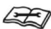
1.1 Ensure the installation complies with the installation minimum dimensions (defined below) and meets the minimum and maximum connecting piping length and maximum change in elevation as defined in the System Requirements section.
1.2 Air inlet and outlet will be clear of obstructions, ensuring proper airflow throughout the room.
1.3 Condensate can be easily and safely drained.
1.4 All connections can be easily made to outdoor unit.
1.5 Indoor unit is out of reach of children.
1.6 A mounting wall strong enough to withstand four times the full weight and vibration of the unit.
1.7 Filter can be easily accessed for cleaning.
1.8 Leave enough free space to allow access for routine maintenance.
1.9 Install at least 10 ft. (3m) away from the antenna of TV set or radio. Operation of the air conditioner may interfere with radio or TV reception in areas where reception is weak. An amplifier may be required for the affected device.
1.10 Do not install in a laundry room or by a swimming pool due to the corrosive environment.
MINIMUM INDOOR CLEARANCES
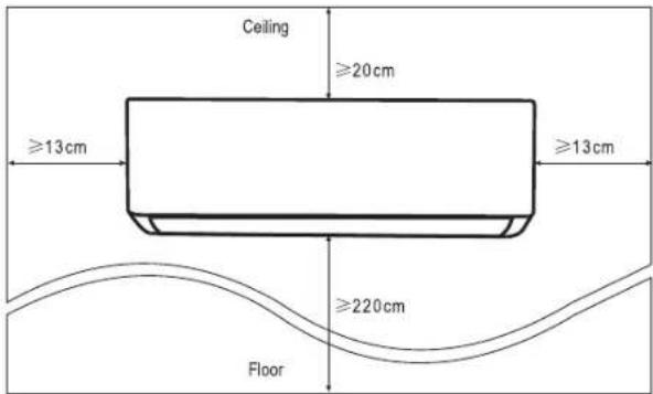
STEP 2: INSTALL MOUNTING PLATE
2.1 Take the mounting plate from the back of indoor unit.
2.2 Ensure to meet the minimum installation dimension requirements as step 1, according to the size of mounting plate, determine the position and stick the mounting plate close to the wall.
2.3 Adjust the mounting plate to a horizontal state with a spirit level, then mark out the screw hole positions on the wall.
2.4 Put down the mounting plate and drill holes in the marked positions with drill.
2.5 Insert expansion rubber plugs into the holes, then hang the mounting plate and fix it with screws
NOTE:
- Make sure the mounting plate is firm enough and flat against the wall after installation.
- This figure shown may be different from the actual object, please take the latter as the standard.
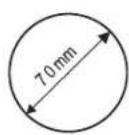
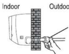
STEP 3: DRILL WALL HOLE
A hole in the wall should be drilled for refrigerant piping, the drainage pipe, and connecting cables.
3.1 Determine the location of wall hole base on the position of mounting plate.
3.2 The hole should be have a 70mm diameter at least and a small oblique angle to facilitate drainage.
3.3 Drill the wall hole with 70mm core drill and with small oblique angle lower than the indoor end about 5mm to 10mm.
3.4 Place the wall sleeve and wall sleeve cover(both are optional parts) to protect the connection parts.
Caution: When drill the wall hole, make sure to avoid wires, plumbing and other sensitive components.
Indoor
Wall sleeve Cover (optional)
Wall sleeve (optional)
Outdoor
5-10mm
Small oblique angle
STEP 4: CONNECTING REFRIGERANT PIPE
4.1 According to the wall hole position, select the appropriate piping mode.
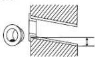
There are three optional piping modes for indoor units as shown in the figure below:
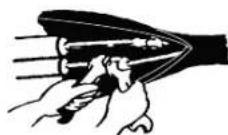
- In Piping Mode 1 or Piping Mode 3, a notch should be made by using scissors to cut the plastic sheet of piping outlet and cable outlet on the corresponding side of the indoor unit.
Note: When cutting off the plastic sheet at the outlet, the cut should be trimmed to smooth.
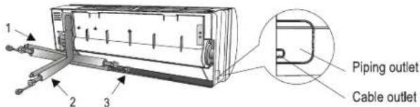
4.2 Bending the connecting pipes with the port facing up as shown in the figure.
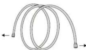
natural_image
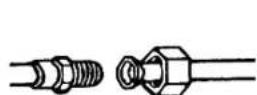
Diagram of two coiled pipes with directional arrows indicating flow or movement (no text or symbols)4.3 Take off the plastic cover in the pipe ports and take off the protective cover on the end of piping connectors.
4.4 Check whether there is any sundry on the port of the connecting pipe and make ensure the port is clean.
4.5 After align the center, rotate the nut of the connecting pipe to tighten the nut as tightly as possible by hand.
4.6 Use a torque wrench to tighten it according to the torque values in the torque requirements table; (Refer to the torque requirements table on section INSTALLATION PRECAUTIONS)
4.7 Wrap the joint with the insulation pipe.
Note: For R32 refrigerant, the connector should be placed outdoors.
The conector shloud be outdoor
STEP 5: CONNECT DRAINAGE HOSE
5.1 Adjust the drainage hose (if applicable)
In some model, both sides of the indoor unit are provided with drainage ports, you can choose one of them to attach the drainage hose. And plug the unused drain port with the rubber attached in one of the ports.
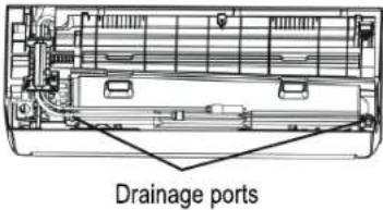
5.2 Connect the drainage hose to the drainage port, ensure the joint is firm and the sealing effect is good.
5.3 Wrap the joint firmly with teflon tape to ensure no leaks.
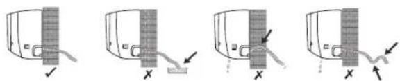
Note: Make sure there is no twists or dents, and the pipes should be placed obliquely downward to avoid blockage, to ensure proper drainage.
natural_image
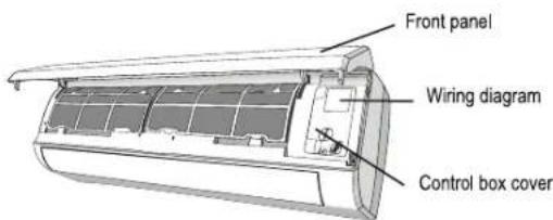
Four-step diagram showing a mechanical or electrical component with arrows indicating movement, no text or symbols present.STEP 6: CONNECT WIRING
6.1 Choose the right cables size determined by the maximum operating current on the nameplate. (Check the cables size refer to section INSTALLATION PRECAUTIONS)
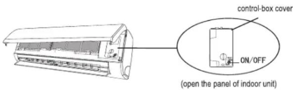
6.2 Open the front panel of indoor unit.
6.3 Use a screwdriver, open the electric control box cover, to reveal the terminal block.
6.4 Unscrew the cable clamp.
6.5 Insert one end of the cable into the position of control box from the back of the right end of the indoor unit.
6.6 Connect the wires to corresponding terminal according to the wiring diagram on the electric control box cover. And make sure that they are well connected.
6.7 Screw the cable clamp to fasten the cables.
6.8 Reinstall the electric control box cover and front panel.
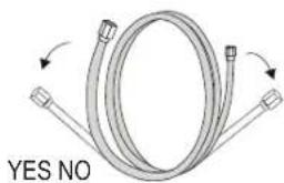
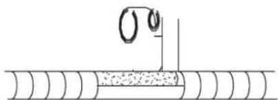
STEP 7: WRAP PIPING AND CABLE
After the refrigerant pipes, connecting wires and drainage hose are all installed, in order to save space, protect and insulate them, it must be bundle with insulating tape before passing them through the wall hole.
7.1 Arrange the pipes, cables and drainage hose well as the following picture.
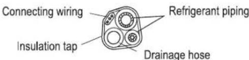
Note: Make sure the drainage hose is at the bottom. Avoid crossing and bending of parts.
7.2 Using the insulating tape wrap the refrigerant pipes, connecting wires and drainage hose together tightly.
natural_image
Pure diagram of a pipe with a circular symbol and a vertical line, no text or labels presentSTEP8: MOUNT INDOOR UNIT
8.1 Slowly pass the refrigerant pipes, connecting wires and drainage hose wrapped bundle through the wall hole.
8.2 Hook the top of indoor unit on the mounting plate.
8.3 Apply slight pressure to the left and right sides of the indoor unit, make sure the indoor unit is hooked firmly.
8.4 Push down the bottom of indoor unit to let the snaps onto the hooks of the mounting plate, and make sure it is hooked firmly.
Sometimes, if the refrigerant pipEs were already embedded in the wall, or if you want to connecting the pips and wires on the wall, do as below:
- Hook the top of the indoor unit on the mounting plate without piping and wiring.
- Lift the indoor unit opposite the wall, unfold the bracket on the mounting plate, and use this bracket to prop up the indoor unit, there will be a big space for operation.
- Do the refrigerant piping, wiring, connect drainage hose, and wrap them as Step 4 to 7.
OUTDOOR UNIT INSTALLATION
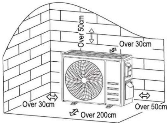
STEP 1: SELECT INSTALLATION LOCATION
Select a site that allows for the following:
1.1 Do not install the outdoor unit near sources of heat, steam or flammable gas.
1.2 Do not install the unit in too windy or dusty places.
1.3 Do not install the unit where people often pass. Select a place where the air discharge and operating sound will not disturb the neighbors.
1.4 Avoid installing the unit where it will be exposed to direct sunlight (other wise use a protection, if necessary, that should not interfere with the air flow).
1.5 Reserve the spaces as shown in the picture for the air to circulate freely.
1.6 Install the outdoor unit in a safe and solid place.
1.7 If the outdoor unit is subject to vibration, place rubber blankets onto the feet of the unit.
STEP 2: INSTALL DRAINAGE HOSE
2.1 This step only for heating pump models.
2.2 Insert the drainage joint to the hole at the bottom of the outdoor unit.
2.3 Connect the drainage hose to the joint and make the connection well enough.

STEP 3: FIX OUTDOOR UNIT
3.1 According to the outdoor unit installation dimensions to mark the installation position for expansion bolts.
3.2 Drill holes and clean the concrete dust and place the bolts.
3.3 If applicable install 4 rubber blankets on the hole before place the outdoor unit (Optional). This will reduce vibrations and noise.
3.4 Place the outdoor unit base on the bolts and pre-drilled holes.
3.5 Use wrench to fix the outdoor unit firmly with bolts
Note: The outdoor unit can be fixed on a wall-mounting bracket. Follow the instruction of the wall-mounting bracket to fix the wall-mounting bracket on the wall, and then fasten the outdoor unit on it and keep it horizontal.
The wall-mounting bracket must be able to support at least 4 times of the weight of outdoor unit.
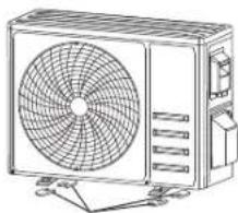
natural_image
Line drawing of a commercial air conditioner unit with fan and control panel (no text or symbols)Install 4 rubber blankets (optional)
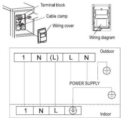
STEP 4: INSTALL WIRING
4.1 Use a Philips screwdriver to unscrew wiring cover, grasp and press it down gently to take it down.
4.2 Unscrew the cable clamp and take it down.
4.3 According to the wiring diagram pasted inside the wiring cover, connect the connecting wires to the corresponding terminals, and ensure all connections are firmly and securely connected.
4.4 Reinstall the cable clamp and wiring cover.
Note: When connecting the wires of indoor and outdoor units, the power should be cut off.
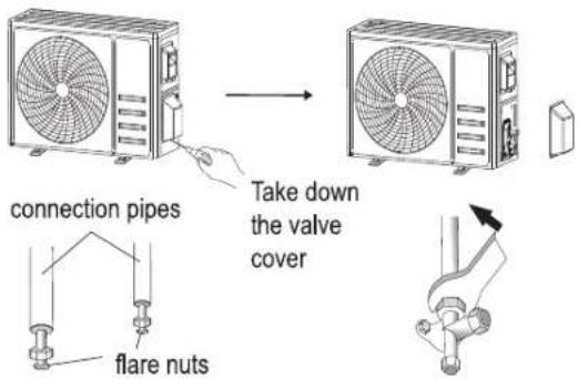
STEP 5: CONNECTING REFRIGERANT PIPE
5.1 Unscrews the valve cover, grasp and press it down gently to take it down (if the valve cover is applicable).
5.2 Remove the protective caps from the end of valves.
5.3 Take off the plastic cover in the pipe ports and check whether there is any sundry on the port of the connecting pipe and make ensure the port is clean.
5.4 After align the center, rotate the flare nut of the connecting pipe to tighten the nut as tightly as possible by hand.
5.5 Use a spanner hold the body of the valve and use a torque wrench to tighten the flare nut according to the torque values in the torque requirements table. (Refer to the torque requirements table on section INSTALLATION PRECAUTIONS)
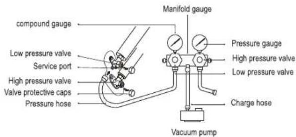
STEP 6: VACUUM PUMPING
6.1 Use a spanner to take down the protective caps from the service port, low pressure valve and high pressure valve of the outdoor unit.
6.2 Connect the pressure hose of manifold gauge to the service port on the outdoor unit low pressure valve.
6.3 Connect the charge hose from the manifold gauge to the vacuum pump.
6.4 Open the low pressure valve of the manifold gauge and close the high pressure valve.
6.5 Turn on the vacuum pump to vacuum the system.
6.6 The vacuum time should not be less than 15 minutes, or make sure the compound gauge indicates -0.1 MPa (-76 cmHg)
6.7 Close the low pressure valve of the manifold gauge and turn off the vacuum.
6.8 Hold the pressure for 5 minutes, make sure that the rebound of compound gauge pointer does not exceed 0.005 MPa.
6.9 Open the low pressure valve counterclockwise for 1/4 turn with hexagonal wrench to let a little refrigerant fill in the system, and close the low pressure valve after 5 seconds and quickly remove the pressure hose.
6.10 Check all indoor and outdoor joints for leakage with soapy water or leak detector.
6.11 Fully open the low pressure valve and high pressure valve of the outdoor unit with hexagonal wrench.
6.12 Reinstall the protective caps of the service port, low pressure valve and high pressure valve of the outdoor unit.
6.13 Reinstall the valve cover.
TEST OPERATION
INSPECTIONS BEFORE TEST RUN
- Do the following checks before test run.
ELECTRICAL SAFETY INSPECTION
- Check whether the power supply voltage complies with specification.
- Check whether there is any wrong or missing connection between the power lines, signal line and earth wires.
- Check whether the earth resistance and insulation resistance comply with requirements.
INSTALLATION SAFETY INSPECTION
- Confirm the direction and smoothness of drainage pipe. Confirm that the joint of refrigerant pipe is installed completely.
- Confirm the safety of outdoor unit, mounting plate and indoor unit installation.
- Confirm that the valves are fully open.
- Confirm that there are no foreign objects or tools left inside the unit. Complete installation of indoor unit air inlet grille and panel.
REFRIGERANT LEAKAGE DETECTION
- The piping joint, the connector of the two valves of the outdoor unit, the valve spool, the welding port, etc., where leakage may occur.
- Foam detection method:
- Apply soapy water or foam evenly on the parts where leakage may occur, and observe whether bubbles appear or not.
- Leak detector method:
- Use a professional leak detector and read the instruction of operation, detect at the position where leakage may occur.
- The duration of leak detection for each position should last for 3 minutes or more.
- If the test result shows that there is leakage, the nut should be tightened and tested again until there is no leakage.
- After the leak detection is completed, wrap the exposed pip connector of indoor unit with thermal insulation material and wrap with insulation tape.
TEST RUN INSTRUCTION
- Turn on the power supply.
- Press the ON/OFF button on the remote controller to turn on the air conditioner.
- Press the Mode button to switch the mode COOL and HEAT. In each mode set as below: COOL-Set the lowest temperature HEAT-Set the highest temperature.
-
Run about 8 minutes in each mode and check all functions are properly run and respond the remote controller. Functions check as recommended:
-
4.1 If the outlet air temperature respond the cool and heat mode
- 4.2 If the water drains properly from the drainage hose
-
4.3 If the Louver and deflectors(optional) rotate properly
-
Observe the test run state of the air conditioner at least 30 minutes.
-
After the successfully test run, return the normal setting and press ON/OFF button on the remote controller to turn off the unit.
- Inform the user to read this manual carefully before use, and demonstrate to the user how to use the air conditioner, the necessary knowledge for service and maintenance, and the reminder for storage of accessories.
Note: If the ambient temperature exceeds the range refer to section OPERATION INSTRUCTIONS, and it can not run COOL or HEAT mode, lift the front panel and refer to the emergency button operation to run the COOL and HEAT mode.
OPERATION INSTRUCTIONS
WARNING: Attempt to use the air conditioner under the temperature beyond the specified range may cause the air conditioner protection device to start and the air conditioner may fail to operate. Therefore, try to use the inverter air conditioner in the following temperature conditions.
| MODE | Heating Cooling Dry | ||
| Room temperature 0°C~30°C | 17°C~32°C | ||
| Outdoor temperature -20°C | ~30°C -15°C~53°C | ||
With the power supply connected, restart the air conditioner after shutdown, or switch it to other mode during operation, and the air conditioner protection device will start. The compressor will resume operation after 3 minutes.
CHARACTERISTICS OF HEATING OPERATION (APPLICABLE TO HEATING PUMP)
PREHÉATING
- When the heating function is enabled, the indoor unit will take 2\~5 minutes for preheating, after that the air conditioner will start heating and blows warm air.
DEFROSTING
- During heating, when the outdoor unit frosted, the air conditioner will enable the automatic defrosting function to improve the heating effect. During defrosting, the indoor and outdoor fans stop running. The air conditioner will resume heating automatically after defrosting finish.
EMERGENCY BUTTON
- Open the panel and find the emergency button on the electronic control box when the remote controller fails. (Always press the emergency button with insulation material.)
| Current status Operation Respond Enter mode | |||
| Standby Press the | emergency button once | It beeps briefly once. | Cooling mode |
| Standby (Only for heating pump) | Press the emergency button twice in 3 seconds | It beeps briefly twice. | Heating mode |
| Running Press the | emergency button once | It keeps beeping for a while | Off mode |
Note: This figure shown may be different from the actual object. please take the latter as the standard.
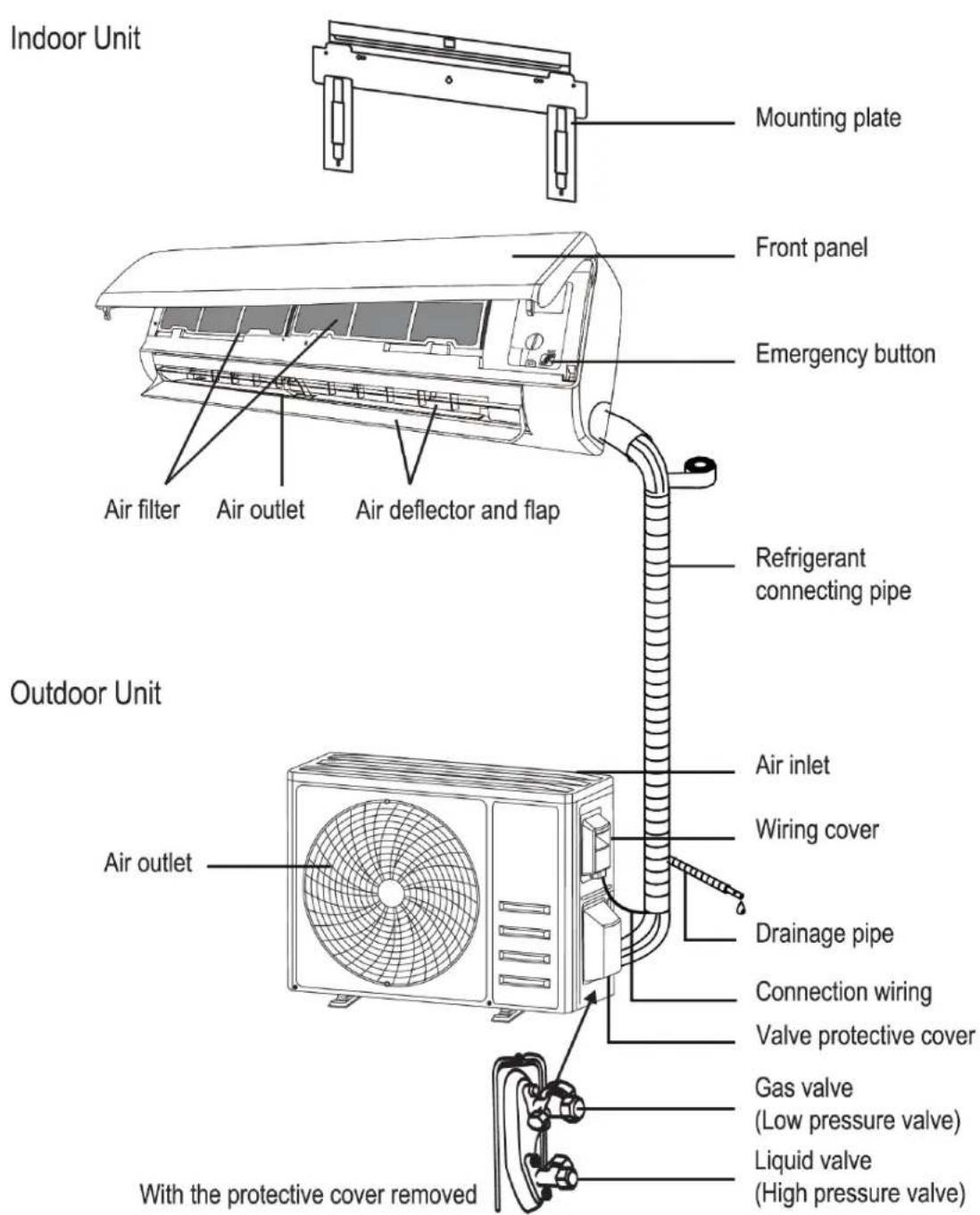
DESCRIPTION OF PARTS
INDOOR UNIT
- Mounting plate
- Front panel
- Air filter
- Air outlet
- Air deflector and flap
- Emergency button
- Refrigerant connecting pipe **
OUTDOOR UNIT
- Air outlet
- Air inlet
- Wiring cover
- Drainage pipe
- Connection wiring **
- Valve protective cover
- Gas valve (low pressure valve)
- Liquid valve (High pressure valve)
** Parts not included
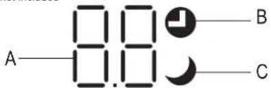
INDOOR UNIT DISPLAY
A Indicator of Timer, temperature and error codes
B Lights up during timer operation
C Sleep mode on
REMOTE CONTROL
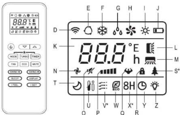
R Child lock
S Health function *
T Sleep function
U I FEEL function
V Gentle Wind *
W ECO mode
X 8 °C heating function *
Y Timer
Z Display On/Off
(*) Function available on some models
flowchart
graph TD
    a -->|+| b
    b --> c
    d --> MODE
    d --> TURBO
    d --> TIMER
    g --> FAN
    g --> ECO
    g --> MUTE
    j --> SWING
    j --> SWING
    l --> SLEEP
    l --> DISPLAY
    n --> IFEEL
    n --> ISET
    f --> e
    i --> h
    k --> m
    o -->
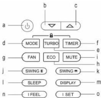
REMOTE CONTROL BUTTONS
a. Switch on/off
b. ▼ To decrease temperature or timer setting hours
c. ▲ To increase temperature or timer setting hours
d. MODE. To select the mode of operation (AUTO, COOL, DRY, FAN, HEAT)
e. TURBO
f. TIMER
g. FAN SPEED
h. ECO
i. MUTE
j. SWING (Up-down)
k. SWING (left-right)
I. SLEEP
m. DISPLAY to switch on/off the LED display
n. I FEEL
0. I SET
p. MODE+TIMER to active/deactivate CHILD-LOCK function
REMOTE CONTROL DISPLAY
D Signal indicator
E Auto mode
F Cooling mode
G Dry mode
H Fan only mode
I Heating Mode
J Battery indicator
K Temperature indicator
L Swing (Up-down)
M Swing (Left-right)
N Fan speed Auto
O Fan speed Mute
P Fan speed low/low-mid/mid/mid-high/high
Q Fan speed Turbo
USE AND CARE
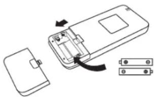
REMOTE CONTROL: REPLACEMENT OF BATTERIES
- Remove the battery cover plate from the rear of the remote control, by sliding it in direction as the arrow.
- Install the batteries according to the direction (+ and -) shown on the Remote control. Reinstall the battery cover by sliding it into place.
- Use 2 pieces LRO3 AAA (1.5V) batteries.
- Do not use rechargeable batteries.
- Replace the old batteries with new ones of the same type when the display is no longer legible.
- Do not dispose batteries as unsorted municipal waste. Collection of such waste separately for special treatment is necessary.
natural_image
Diagram of a device showing an open rear panel, internal battery casing, and two separate components (no text or symbols)NOTE: For some model, each time when insert the batteries in the remote controller for the first time, you can set the Cooling only or the Heating pump control type. As soon as you insert the batteries, turn off the remote controller, and operate as below:
- Long press the MODE button, until the ✿ icon flash, to set the Cooling only type.
- Long press the MODE button, until the pump type. (Cooling and Heating)
NOTE: If you set the remote control in cooling mode, it will not be possible to activate the heating function in units with a heating pump. If you need to reset, take out the batteries and install again.
USE COOLING MODE
- The cooling function allows the air conditioner to cool the room and reduce Air humidity at the same time.
- To activate the cooling function (COOL), press the MODE button (d) until the symbol of cooling (F) appears on the display.
- With the buttons ▼ (b) or ▲ (c) set a temperature lower than that of the room.
FAN MODE
- Fan mode, air ventilation only.
- To set the FAN mode, press MODE button (d) until the FAN Only Mode (H) appears on the display.
- This function reduces the humidity of the air to make the room more comfortable.
- To set the DRY mode, Press MODE button (d) until the DRY icon (G) appears in the display. An automatic function of pre-setting is activated.
AUTO MODE
- Automatic mode
- To set the AUTO mode, press MODE button (d) until the icon of Auto Mode (E) appears on the display.
- In AUTO mode the run mode will be set automatically according to the room temperature.
HEATING MODE
- The heating function allows the air conditioner to heat the room.
- To activate the heating function (HEAT), press the MODE button (d) until the icon of heating (l) appears on the display.
- With the increase button ▲ (c) or decrease button ▼ (b) set a temperature higher than that of the room.
NOTE: In HEATING operation, the appliance can automatically activate a defrost cycle, which is essential to clean the frost on the condenser so as to recover its heat exchange function.
- This procedure usually lasts for 2-10 minutes. During defrosting, indoor unit fan stop operation. After defrosting, it resumes to HEATING mode automatically.
FAN SPEED
• To change the operating fan speed.
- Press the FAN SPEED button (g) to set the running fan speed. It can be set to AUTO/ MUTE/ LOW/ LOW-MID/ MID/ MID-HIGH/ TURBO.
- The display will show the selected fan speed with the following icons:
- (N) for fan speed AUTO, (O) for fan speed MUTE, (P) for fan speed LOW/LOW-MID/MID/MID-HIGH, (Q) for fan speed TURBO
CHILD-LOCK FUNCTION
- Long press the buttons MODE (d) and TIMER (f) together to active this function, and do it again to deactivate this function. Under CHILD-LOCK function, no single button will be active.
TIMER FUNCTION TIMER ON
- To automatic switch on the appliance. When the unit is switch-off, you can set the TIMER ON.
-
To set the time of automatic switch-on do as below:
-
Press TIMER button (f) first time to set the switch-on. The TIMER icon (Y) will flash on the display.
- Press the increase button ▲ (c) or decrease button ▼ (b) to set desired timer-on time. Each time you press the button, the time increases/decreases by half an hour between 0 and 10 hours and by one hour between 10 and 24 hours.
- Press TIMER button (f) second time to confirm.
- After Timer-on setting, set the needed mode (COOL / HEAT / AUTO / FAN / DRY), by pressing the MODE button (d). And set the desired fan speed by pressing the FAN SPEED button (g). Then press increase ▲ (c) and decrease ▼ (b) to set the desired operation temperature.
- Cancel it by pressing again the TIMER button (f).
TIMER OFF
- To automatic switch off the appliance. When the unit is switch-on, you can set the TIMER OFF.
-
To set the time of automatic switch-off, do as below:
-
Confirm the appliance is on.
- Press the TIMER button (f) at first time to set the switch-off.
- Press the increase button ▲ (c) or decrease button ▼ (b) to set desired timer-off time.
- Press TIMER button (f) to confirm.
- Cancel it by pressing again the TIMER button (f).
Note: All programming should be operated within 5 seconds, otherwise the setting will be cancelled.
SWING FUNCTION
- Press the button SWING to activate the louver.
- Press swing to activate the horizontal flaps to swing from up to down, the icon up-down swing will appear on the remote display. Press again to stop the swing movement at the current angle.
- Press swing to activate the vertical deflectors to swing from left to right, the icon will appear on the remote-control display.
- Press again to stop the swing movement at the current angle.
CAUTION: Never position flaps manually, the delicate mechanism might be seriously damaged.
CAUTION: Never put fingers, sticks or other objects into the air inlet or outlet vents, it might cause unforeseeable damage or injury.
TURBO FUNCTION
- To activate turbo function, press the TURBO button (e), and the TURBO icon (Q) will appear on the display of the remote control. Press again to cancel it.
- In COOL/HEAT mode, when you select the TURBO feature, the appliance will turn to quick COOL or quick HEAT mode, and operate to the highest fan speed to blow strong airflow.
NOTE: For some model of remote controller, you can program the temperature display between ^ C and ^ F.
- Press and hold the TURBO button over 5 seconds to get into the change mode.
- Press and hold the TURBO button, until it switches to ^ C and ^ F .
- Then release the pressing and wait for 5 seconds, the function will be selected.
MUTE FUNCTION
- Press MUTE button (i) to activate this function, and the icon (O) will appear in the remote-control display. Do it again to deactivate this function.
- When mute function runs, the remote control will display the auto fan speed, and the indoor unit will operate at lowest fan speed.
- If the button FAN (g) / TURBO (e) / SLEEP (l) is pressed, the mute function will be cancelled.
- MUTE function can not be activate under dry mode.
SLEEP FUNCTION
• Pre-setting automatic operating program.
- Press sleep button (I) to activate the SLEEP function, and the icon (T) will appear in the remote control display.
- Press again to cancel this function.
• After 10 hours running in sleep mode, the air conditioner will change to the previous setting mode.
ECO FUNCTION
- In this mode the appliance automatically sets the operation to save energy.
- Press the ECO button(h), the ECO icon (W) will appear in the remote control display, and the appliance will run in ECO mode. Press again to cancel it.
NOTE: The ECO function is available in both COOLING and HEATING modes.
DISPLAY FUNCTION (INDOOR UNIT DISPLAY)
- Switch ON/OFF the LED display on panel. Press the DISPLAY button (m) to switch off the LED display on the panel. Press again to switch on the LED display.
I FEEL FUNCTION (OPTIONAL)
- Press the I FEEL button (n) to activate this function. The icon (U) will appear on the display.
- This function enables the remote control to measure the temperature as its current location, and send the signal to the air conditioner to optimize the temperature around you and ensure the comfort.
- It will automatically deactivate 2 hours later.
I SET FUNCTION (OPTIONAL)
- This function remembers your favorite setting and runs it by pressing one single button. For memorize your favorite setting do as below:
- In each mode (COOLING/HEATING/FAN/DRY), long press "I SET" button over 3 seconds to remember it.
- When "AU" flashing appears on the remote controller display, that means the remote controller remember your favorite setting.
- Press any button to quit, and you can reset it by repeating steps 1 and 2.
- Run your favorite setting:
- In each mode (COOLING/HEATING/FAN/DRY), press once "I SET" button to active.
- The appliance will run as your favorite setting and you will see [AU] flashing on the remote controller.
- Press it again or any other button to cancel this function.
CLEANING
WARNING
- When cleaning, you must shut down the machine and cut off the power supply for more than 5 minutes.
- Under no circumstances should the air conditioner be flushed with water.
- Pay attention to cleaning the filter screen regularly to avoid dust covering which will affect the filter screen effect. When the operating environment is dusty, the cleaning frequency should be increased appropriately.
- After removing the filter screen, do not touch the fins of the indoor unit to avoid scratching.
CLEANING THE SURFACE
- Clean the unit with a slightly damp cloth. Gentle wipe the unit surface.
- Only use soft dry cloth or wet cloth dipped with neutral detergent to clean the air conditioner. Do not use solvents or products with an acidic or basic pH factor such as bleach or abrasive products to clean it as it will damage the air conditioner.
- Wipe frequently to keep the air conditioner clean and its good appearance.
CLEANING THE FILTERS
• Take out the filter from the unit.
- Clean the filter with soapy water and let it dry completely.
- Replace the filter.
Note: When you find accumulated dust in the filter, please clean the filter in time to ensure the clean, healthy and efficient operation inside the air conditioner.
ANOMALIES AND REPAIR
SERVICE
- Any person who is involved with working on or breaking into a refrigerant circuit should hold a current valid certificate from an industry accredited assessment authority, which authorizes their competence to handle refrigerants safely in accordance with an industry recognized assessment specification.
- Servicing shall only be performed as recommended by the equipment manufacturer. Maintenance and repair requiring the assistance of other skilled personnel shall be carried out under the supervision of the person competent in the use of flammable refrigerants.
- Make sure that the appliance is serviced only by specialist personnel, and that only original spare parts or accessories are used to replace existing parts/accessories.
- You can request technical assistance at atencioncliente@taurus.es
- Any improper use, or in disagreement with the instructions for use, can be dangerous, voiding the manufacturer's warranty and liability.
- When the air conditioner is not in use for a long time, take out the batteries of the remote controller and disconnect the power supply of the air conditioner.
-
When starting to use after long-term shutdown:
-
Clean the unit and filter screen;
- Check whether there are obstacles at the air inlet and outlet of indoor and outdoor units;
- Check whether the drain pipe is unobstructed;
- Install the batteries of the remote controller and check whether the power is on.
TROUBLESHOOTING
- If any fault is detected, refer to the following table:
| ANOMALIES POSSIBLE CAUSES | |
| The appliance does not operate | Power failure/plug pulled out. |
| Damaged indoor/outdoor unit fan motor. | |
| Faulty compressor thermomagnetic circuit breaker. | |
| Faulty protective device or fuses. | |
| Loose connections or plug pulled out. | |
| It sometimes stops operating to protect the appliance. | |
| Voltage higher or lower than the voltage range. | |
| Active TIMER-ON function. | |
| Damaged electronic control board. | |
| Strange odor Dirty air filter. | |
| Noise of running water Back flow of liquid in the refrigerant circulation. | |
| A fine mist comes from the air outlet | This occurs when the air in the room becomes very cold, for example in the COOLING or DEHUMIDIFYING/DRY modes. |
| A strange noise can be heard | This noise is made by the expansion or contraction of the front panel due to variations in temperature and does not indicate a problem. |
| Insufficient airflow, either hot or cold | Unsuitable temperature setting. |
| Obstructed air conditioner intakes and outlets. | |
| Dirty air filter. | |
| Fan speed set at minimum. | |
| Other sources of heat in the room. | |
| No refrigerant. | |
| The appliance does not respond to commands | Remote control is not close enough to indoor unit. |
| The batteries of remote control need to be replaced. | |
| Obstacles between remote control and signal receiver in indoor unit. | |
| The display is off Active DISPLAY function. | |
| Switch off the air conditioner immediately and cut off the power supply in the event of: | Strange noises during operation. |
| Faulty electronic control board. | |
| Faulty fuses or switches. | |
| Spraying water or objects inside the appliance. | |
| Overheated cables or plugs. | |
| Very strong smells coming from the appliance. | |
ERROR CODE ON THE DISPLAY
- In case of error, the display on the indoor unit shown the following error codes:
| Display Description of the trouble | |
| E1 | Indoor room temperature sensor fault |
| E2 | Indoor pipe temperature sensor fault |
| E3 | Outdoor pipe temperature sensor fault |
| E4 | Refrigerant system leakage or fault |
| E6 | Malfunction of indoor fan motor |
| E7 | Outdoor ambient temperature sensor fault |
| E0 | Indoor and outdoor communication fault |
| E8 | Outdoor discharge temperature sensor fault |
| E9 | Outdoor IPM module fault |
| EA | Outdoor current detect fault |
| EE | Outdoor PCB EEPROM fault |
| EF | Outdoor fan motor fault |
| EH | Outdoor suction temperature sensor fault |
- This appliance contains refrigerant and other potentially hazardous materials. When disposing of this appliance, the law requires special collection and treatment. DO NOT dispose of this product ashousehold waste or unsorted municipal waste.
- When disposing of this appliance, you have the following options:
Dispose of the appliance at designated municipal electronic waste collection facility. If you want to dispose of the product, after the end of its life, you must deposit it by the appropriate means at the disposal of an authorized waste manager for the selective collection of Waste Electrical and Electronic Equipment (WEEE).

The product may have batteries or batteries inside it, which must be removed before disposing of the product. Remember that batteries must be disposed of in special authorized containers. And they should never be thrown into the fire.
REGULATORY INFORMATION
CONNECTIVITY DATA
• 2,4 GHz Wi-Fi: standard IEEE 802.11b/g/n(HT20).
• The 2.4 GHz band is limited to operate between 2412 MHz - 2472 MHz.
- This appliance complies with Directive 2014/53/EU on radio equipment, including the objectives with respect to safety requirements set out in Directive 2014/35/EU, an adequate level of electromagnetic compatibility as set out in Directive 2014/30/EU,
- This appliance also complies with Directive 2011/65/EU and its amending Directive (EU) 2015/863 on the restrictions of the use of certain hazardous substances in electrical and electronic equipment and Directive 2009/125/EC on the ecodesign requirements for energy-related products.
CE
- Hereby, Electrodomésticos Taurus, S.L. declares that the Single Split Air Conditioner PRO SERIE WIFI is in compliance with Directive 2014/53/EU. The full text of the EU declaration of conformity is available at the following internet address: https://taurus-home.com/
| Information requirements for air conditioners, regulation (EU) 206/2012 | |||||||
| Function (indicate if present) | If function includes heating: Indicate the heating season the information relates to. Indicated values should relate to one heating season at a time. Include at least the heating season 'Average'. | ||||||
| cooling Y Average (mandatory) Y | |||||||
| heating Y Warmer (if designated) Y | |||||||
| Colder (if designated) N | |||||||
| Item symbol value unit Item symbol | value unit | ||||||
| Design load Seasonal efficiency | |||||||
| cooling | Pdesignc | 3,40 | kW | cooling | SEER | 6,10 | — |
| heating/Average | Pdesignh | 2,10 | kW | heating/Average | SCOP/A | 4,00 | — |
| heating/Warmer | Pdesignh | 2,40 | kW | heating/Warmer | SCOP/W | 5,10 | — |
| heating/Colder | Pdesignh | N/A | kW | heating/Colder | SCOP/C | N/A | — |
| Declared capacity for cooling, at indoor temperature 27(19) °C and outdoor temperature Tj | Declared energy efficiency ratio, at indoor temperature 27(19) °C and outdoor temperature Tj | ||||||
| Tj = 35 °C | Pdc | 3,40 | kW | Tj = 35 °C | EERd | 2,92 | — |
| Tj = 30 °C | Pdc | 2,34 | kW | Tj = 30 °C | EERd | 4,75 | — |
| Tj = 25 °C | Pdc | 1,49 | kW | Tj = 25 °C | EERd | 8,00 | — |
| Tj = 20 °C | Pdc | 0,86 | kW | Tj = 20 °C | EERd | 11,30 | — |
| Declared capacity for heating / Average season, at indoor temperature 20°C and outdoor temperature Tj | Declared coefficient of performance / Average season, at indoor temperature 20°C and outdoor temperature Tj | ||||||
| Tj = -7 °C | Pdh | 1,86 | kW | Tj = -7 °C | COPd | 2,62 | — |
| Tj = 2 °C | Pdh | 1,19 | kW | Tj = 2 °C | COPd | 4,11 | — |
| Tj = 7 °C | Pdh | 0,79 | kW | Tj = 7 °C | COPd | 5,05 | — |
| Tj = 12 °C | Pdh | 0,77 | kW | Tj = 12 °C | COPd | 5,87 | — |
| Tj = bivalent temperature,-7 °C | Pdh | 1,86 | kW | Tj = bivalent temperature | COPd | 2,62 | — |
| Tj = operating limit, -15°C | Pdh | 2,08 | kW | Tj = operating limit | COPd | 2,42 | — |
| Declared capacity for heating / Warmer season, at indoor temperature 20°C and outdoor temperature Tj | Declared coefficient of performance / Warmer season, at indoor temperature 20°C and outdoor temperature Tj | ||||||
| Tj = 2 °C | Pdh | 2,40 | kW | Tj = 2 °C | COPd | 3,08 | — |
| Tj = 7 °C | Pdh | 1,55 | kW | Tj = 7 °C | COPd | 5,15 | — |
| Tj = 12 °C | Pdh | 0,77 | kW | Tj = 12 °C | COPd | 5,94 | — |
| Tj = bivalent temperature | Pdh | 2,40 | kW | Tj = bivalent temperature | COPd | 3,08 | — |
| Tj = operating limit | Pdh | 2,40 | kW | Tj = operating limit | COPd | 3,08 | — |
| Declared capacity for heating / Colder season, at indoor temperature 20°C and outdoor temperature Tj | Declared coefficient of performance / Colder season, at indoor temperature 20°C and outdoor temperature Tj | ||||||
| Tj = -7 °C | Pdh | N/A | kW | Tj = -7 °C | COPd | N/A | — |
| Tj = 2 °C | Pdh | N/A | kW | Tj = 2 °C | COPd | N/A | — |
| Tj = 7 °C | Pdh | N/A | kW | Tj = 7 °C | COPd | N/A | — |
| Tj = 12 °C | Pdh | N/A | kW | Tj = 12 °C | COPd | N/A | — |
| Tj = bivalent temperature | Pdh | N/A | kW | Tj = bivalent temperature | COPd | N/A | — |
| Tj = operating limit | Pdh | N/A | kW | Tj = operating limit | COPd | N/A | — |
| Tj = -15 °C | Pdh | N/A | kW | Tj = -15 °C | COPd | N/A | — |
| Bivalent temperature | Operating limit temperature | ||||||
| heating/Average | Tbiv | -7 | °C | heating/Average | Tol | -15 | °C |
| heating/Warmer | Tbiv | 2 | °C | heating/Warmer | Tol | 2 | °C |
| heating/Colder | Tbiv | N/A | °C | heating/Colder | Tol | N/A | °C |
| Cycling interval capacity | Cycling interval efficiency | ||||||
| for cooling | Pcycc | N/A | kW | for cooling | EERcyc | N/A | — |
| for heating | Pcych | N/A | kW | for heating | COPcyc | N/A | — |
| Degradation co-efficient cooling | Cdc | 0,25 | — | Degradation co-efficient heating | Cdh | 0,25 | — |
| Electric power input in power modes other than 'active mode' | Annual electricity consumption | ||||||
| off mode | POFF | — | kW | cooling | QCE | 195 | kWh/a |
| standby mode | PSR | 0,005 | kW | heating/Average | QHE | 735 | kWh/a |
| thermostat-off mode | PTG | 0,020 | kW | heating/Warmer | QHE | 659 | kWh/a |
| crankcase heater mode | PCK | — | kW | heating/Colder | QHE | — | kWh/a |
| Capacity control (indicate one of three options) | Other items | ||||||
| fixed | N | Sound power level (indoor/outdoor) | LVA | 50 / 60 | dB(A) | ||
| staged | N | Global warming potential | GWP | 675 | kgCO2 eq. | ||
| variable | Y | Rated air flow (indoor/outdoor) | — | indoor: 550 outdoor: 1700 | m3/h | ||
| Contact details for obtaining more information: contact@taurus.es | Electrodomésticos Taurus, S.L. Avda. Barcelona, s/n, 25790 Oliana, Lleida (Spain) | ||||||


FR
| TYPE D'INVERSEUR MODÈLE capacité (Btu/h) | 9k 12k | 18k | 24k | ||
| zone sectionnelle | |||||
| Câble d'alimentation | N | 1.5mm^7 | 1.5mm^7 | 1.5mm^2 | 2.5mm^2 |
| L | 1.5mm^7 | 1.5mm^7 | 1.5mm^2 | 2.5mm^2 | |
| + | 1.5mm^2 | 1.5mm^2 | 1.5mm^2 | 2.5mm^2 | |
| Câble de raccordement | N | 0.75mm^2 | 0.75mm^2 | 0.75mm^2 | 0.75mm^2 |
| L ou (L) | 0.75mm^2 | 0.75mm^2 | 0.75mm^2 | 0.75mm^2 | |
| 1 | 0.75mm^2 | 0.75mm^2 | 0.75mm^2 | 0.75mm^2 | |
| + | 0.75mm^2 | 0.75mm^2 | 0.75mm^2 | 0.75mm^2 | |
NOTE:
natural_image
Technical line drawing of a mechanical assembly with no visible text or symbolsOrifices de drainage