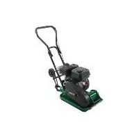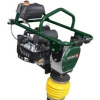
PVS 4780 A1 - Vibratory plate PARKSIDE - Free user manual and instructions
Find the device manual for free PVS 4780 A1 PARKSIDE in PDF.


| Product type | Vibratory plate |
| Brand | Parkside |
| Model | PVS 4780 A1 |
| Dimensions (L x W x H) | 480 x 780 x 1150 mm |
| Plate dimensions (L x W) | 345 x 285 mm |
| Plate stroke | 40 - 66 mm |
| Vibration frequency | 450 - 650 min⁻¹ |
| Centrifugal force | 10 kN |
| Engine type | 1 cylinder, 4-stroke |
| Max engine power | 4.1 kW |
| Displacement | 196 cm³ |
| Recommended fuel | Super E10 |
| Fuel tank capacity | 2.8 L |
| Engine oil | SAE 10W-30 or SAE 10W-40 |
| Engine oil quantity | 0.6 L |
| Tamping lubrication | SAE 10W-30, 0.8 L |
| Spark plug | F7RTC (gap 0.7-0.8 mm) |
| Weight | 78 kg |
| Sound power level | 108 dB (guaranteed) |
| Handle vibrations (right/left) | 30.61 / 29.37 m/s² |
| Intended use | Compaction of loose soil, earth, gravel |
| Warranty | 3 years |
| Included accessories | Transport device, spark plug wrench, collar, screws, protective frame |
| Cleaning and maintenance | Engine oil change every 50h, air filter every 100h |
Frequently Asked Questions - PVS 4780 A1 PARKSIDE
User questions about PVS 4780 A1 PARKSIDE
0 question about this device. Answer the ones you know or ask your own.
Ask a new question about this device
Download the instructions for your Vibratory plate in PDF format for free! Find your manual PVS 4780 A1 - PARKSIDE and take your electronic device back in hand. On this page are published all the documents necessary for the use of your device. PVS 4780 A1 by PARKSIDE.
USER MANUAL PVS 4780 A1 PARKSIDE
natural_image
Industrial power tool with mechanical components and wiring (no visible text or symbols)
text_image
PDF ONLINE www.lidl-service.comTAMPER - PVS 4780 A1 VIBRATIONSSTAMPFER - PVS 4780 A1 PILONNEUSE - PVS 4780 A1
GBENICYMT
TAMPER
Operating and Safety Instructions
Translation of Original Operating Manual
FR BE CH
PILONNEUSE
Before reading, unfold the page containing the illustrations and familiarise yourself with all functions of the device.
DE AI CH
GB / IE / NI / CY / MT Operating and Safety Instructions Page 01
text_image
Technical diagram of a sewing machine with numbered parts for identification and assembly reference.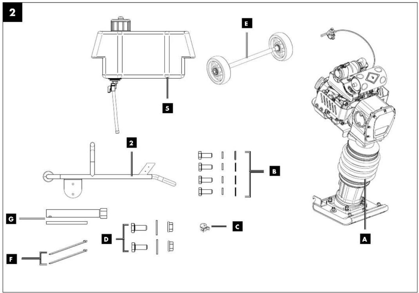
text_image
Technical diagram of a robotic arm with labeled components including chassis, wheels, and base parts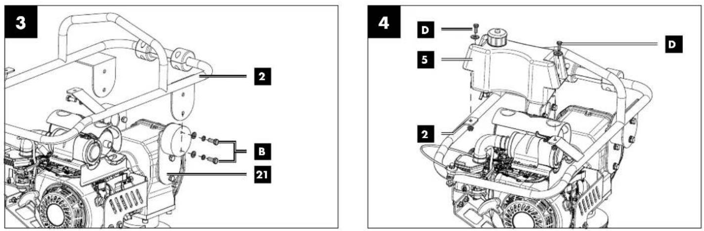
text_image
Technical diagram of a vehicle engine assembly with labeled components and numbered parts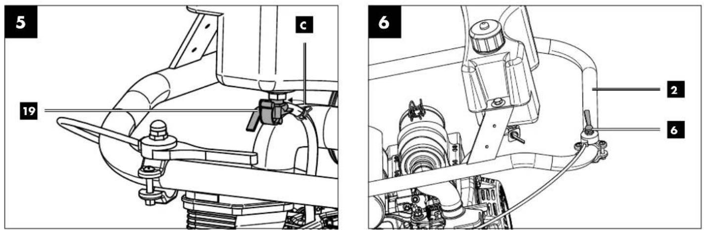
text_image
5 c 19 6 2 6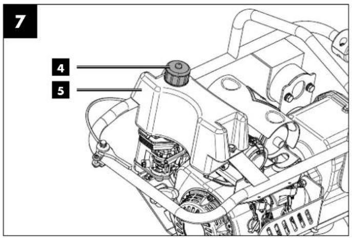
text_image
7 4 5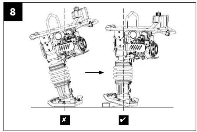
text_image
8 X ✓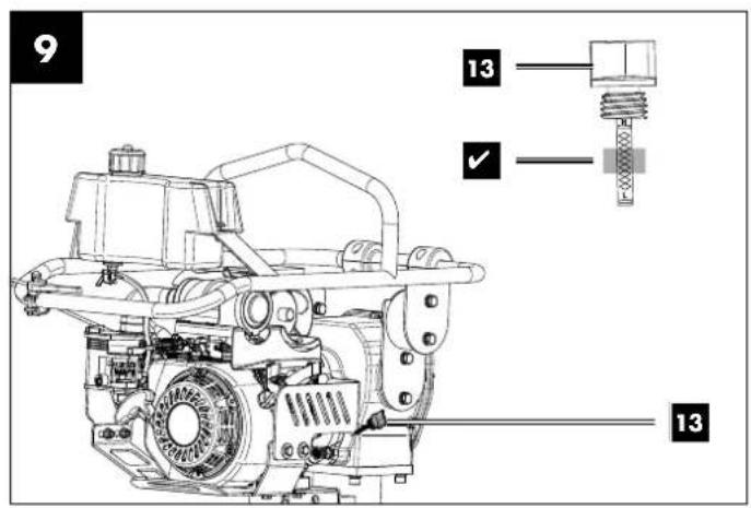
text_image
9 13 ✓ 13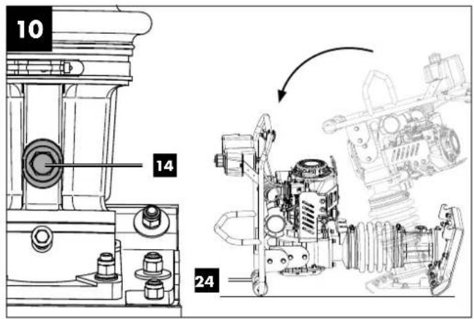
text_image
10 14 24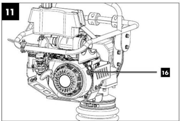
text_image
11 16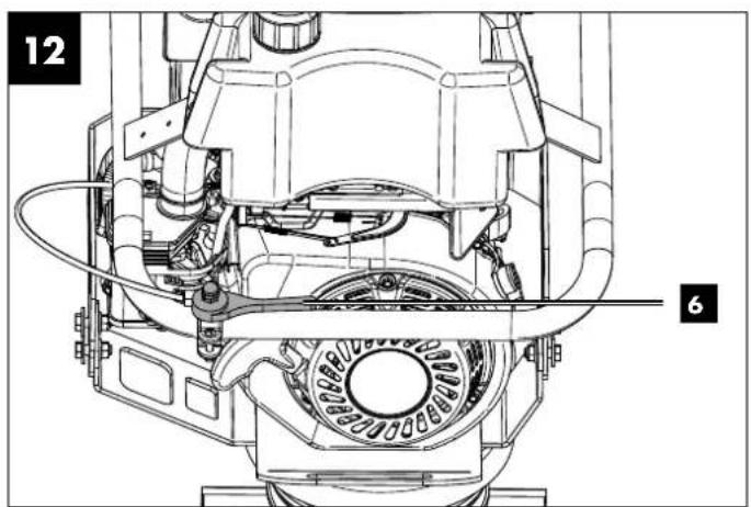
natural_image
Technical line drawing of a mechanical assembly with labeled parts (12 and 6), no readable text or symbols beyond labels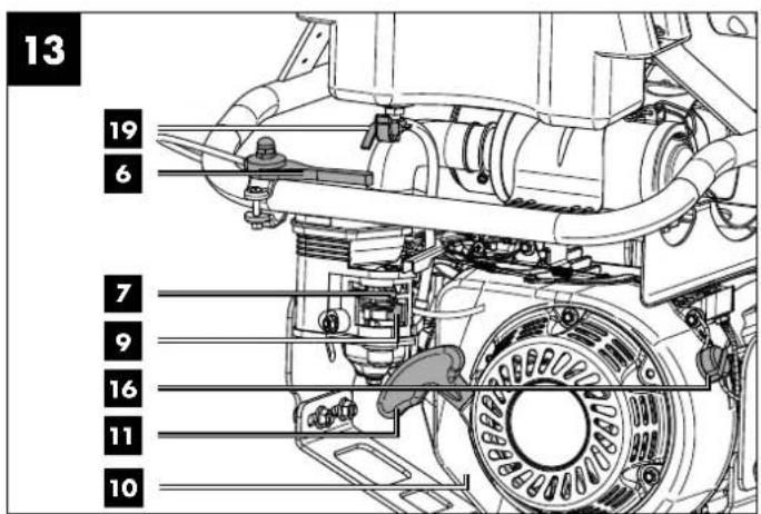
text_image
13 19 6 7 9 16 11 10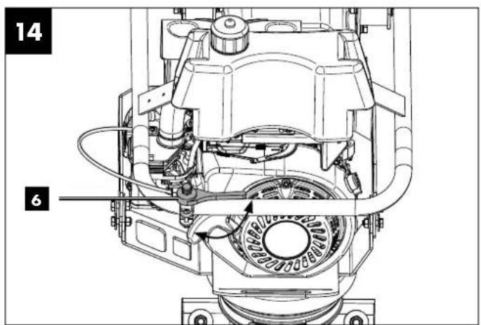
text_image
14 6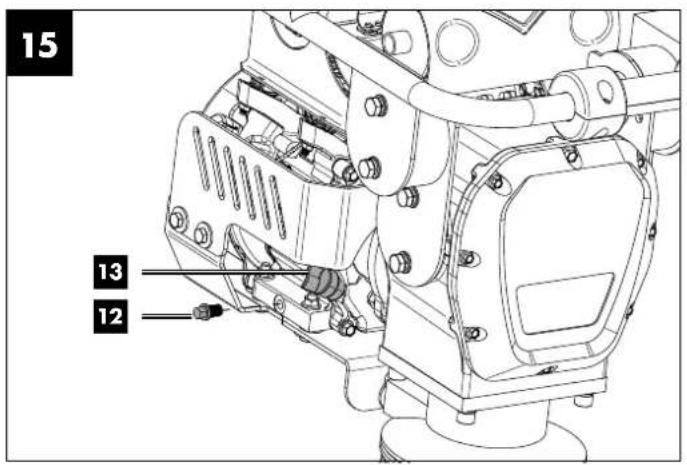
text_image
15 13 12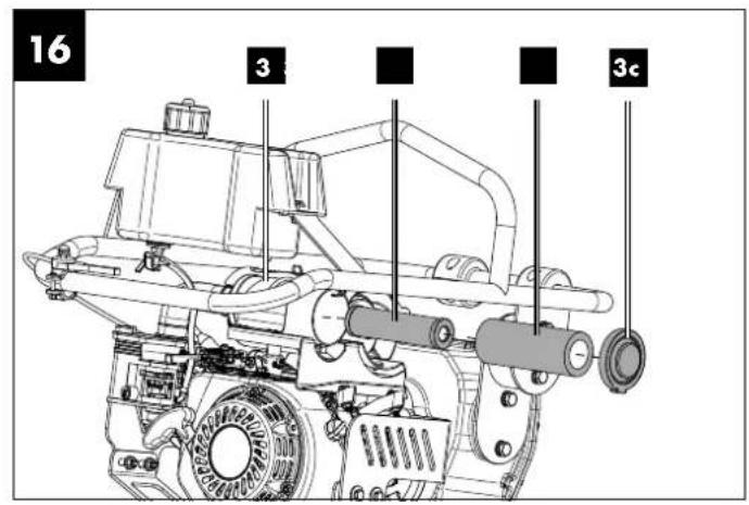
text_image
16 3 3c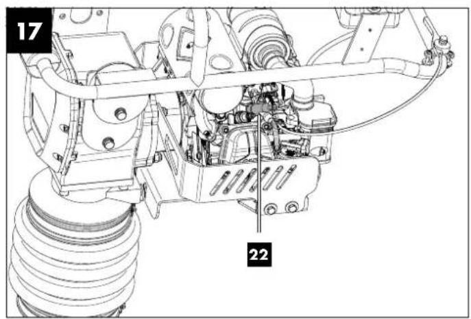
text_image
17 22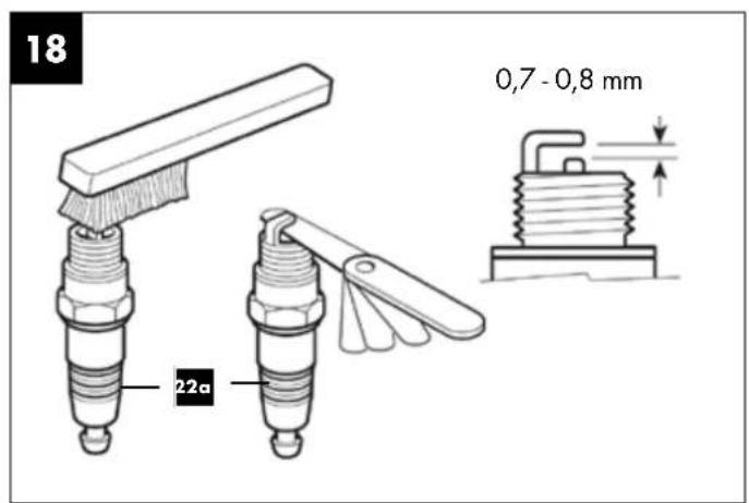
text_image
18 22a 0,7 - 0,8 mm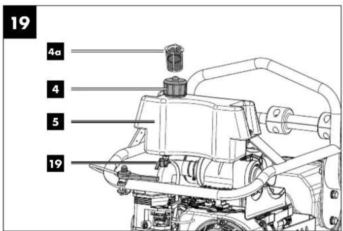
text_image
19 4a 4 5 19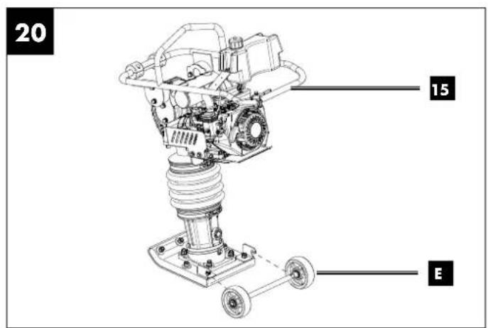
text_image
20 15 ETable of contents: Page:
- Explanation of the symbols on the device....2
- Introduction......5
- Device description (Fig. 1) ....5
- Scope of delivery (fig. 2)......5
- Proper use....5
- General safety instructions ....6
- Technical data....8
- Unpacking....9
- Layout 9
- Before commissioning....9
- Commissioning....11
- Cleaning and maintenance....12
- Transporting and lifting the machine....14
- Storage....15
- Disposal and recycling 15
- Troubleshooting....16
- Warranty certificate....17
- Exploded view....106
- Declaration of conformity....108
1. Explanation of the symbols on the device











Before commissioning, read and observe the operating manual and safety instructions!
Wear safety goggles!
Wear hearing protection!
Use work gloves.
Use safety shoes.
Do not expose the device to rain.
Lifting point, on which the machine can be securely fastened, e.g. to load onto a transport vehicle.
Lifting point is used to secure the machine during transport.
Removing or modifying protective or safety equipment is prohibited.
Do not touch rotating parts. Getting caught in the spinning belt will cause a hand injury. Always put on the belt guard.
Naked flames or smoking near the device is strictly prohibited!



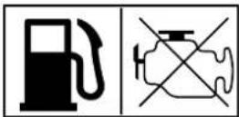
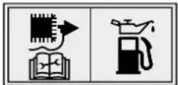

ON / OFF
Hot surface! Touching can cause burns. Only carry out servicing, maintenance and cleaning work when the engine has cooled down.
Warning - Hot parts! Make sure that other persons maintain a sufficient safety distance. Keep uninvolved persons away from the device.
Sparks are produced when the engine is started. These can ignite nearby flammable gases.
Danger of poisoning! Only use the device outdoors and never in closed or poorly ventilated rooms.
Important: Always switch off the engine before refuelling. Do not refill during operation.
Before carrying out any cleaning or maintenance work, switch off the engine and remove the spark plug connector from the spark plug. Be very careful when dealing with fuels and lubricants!
Guaranteed sound power level of the device.
On/off switch
The machine complies with the applicable European directives.


We have marked points in this operating manual that impact your safety with this symbol.
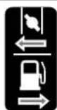
- Choke closed - Open fuel valve
 | Speed lever |
 | Checking the oil level |
| DANGER! | Signal word to indicate an imminently hazardous situation which, if not avoided, will result in death or serious injury. |
| WARNING! | Signal word to indicate a potentially hazardous situation which, if not avoided, could result in death or serious injury. |
| CAUTION! | Signal word to indicate a potentially hazardous situation which, if not avoided, could result in minor or moderate injury. |
| NOTE | Signal word for marking a potentially hazardous situation which, if not avoided, could result in material damage to the machine or property/possessions. |
2. Introduction
MANUFACTURER:
Scheppach GmbH
Günzburger Straße 69
D-89335 Ichenhausen
DEAR CUSTOMER,
we wish you much pleasure and success in working with your new device.
NOTE:
In accordance with the applicable product liability laws, the manufacturer of this device assumes no liability for damage to the device or caused by the device arising from:
- Improper handling,
• Non-compliance with the operating manual, - Repairs carried out by third parties, unauthorised specialists,
• Installing and replacing non-original spare parts,
• Application other than specified.
Note:
Read the whole text of the operating manual before assembly and commissioning.
This operating manual should help you to familiarise yourself with your device and to use it for its intended purpose.
The operating manual includes important instructions for safe, proper and economic operation of the device, for avoiding danger, for minimising repair costs and downtimes, and for increasing the reliability and extending the service life of the device.
In addition to the safety instructions in this operating manual, you must also observe the regulations applicable to the operation of the device in your country.
Keep the operating manual at the device, in a plastic sleeve, protected from dirt and moisture. They must be read and carefully observed by all operating personnel before starting the work.
The device may only be used by personnel who have been trained to use it and who have been instructed with respect to the associated hazards. The required minimum age must be observed.
In addition to the safety instructions in this operating manual and the separate regulations of your country, the generally recognised technical rules relating to the operation of such machines must also be observed.
We accept no liability for accidents or damage that occur due to a failure to observe this manual and the safety instructions.
3. Device description (Fig. 1)
- Transport bar
- Protective frame
- Air filter
3a. Paper filter
3b. Foam filter
3c. Air filter housing cover - Fuel filler cap
4a. Fuel filter insert - Fuel tank
- Throttle
- Choke lever
- Ventilation hose
- Fuel valve on the engine
- Engine
- Pull starter
- Oil drain screw
- Oil dipstick
- Rammer foot oil drain screw
- Guide bar
- On/off switch
- Bottom rammer
- Rammer foot
- Fuel valve on the fuel tank
- Transmission
- Adapter plates (2x)
- Spark plug connector
22a.Spark plug - Silencer
- Transport roller
4. Scope of delivery (fig. 2)
• Vibration rammer (A)
- 4 x Hexagon bolts M10x25 (B)
- 1 x Hose clamp (C)
- 2 x Hexagonal bolts (D)
- 1 x Transport device (E)
- 2 x Cable ties (F)
- 1 x Spark plug wrench (C)
- 1 x Protective frame (2)
- 1 x Fuel tank (5)
- 2 x Adapter plates (21)
- 1 x Operating manual
5. Proper use
The machine complies with the applicable EC machinery directive.
The machine is a motor-driven tool and is suitable for compacting loose soil, clods of earth and gravel, thereby creating a firm and stable base for foundations, sub-concrete and other subsoil consolidation.
However, the machine is not suitable for compacting soils with a high clay content.
The machine may only be used in the intended manner. Any use beyond this is improper. The machine may only be operated by persons who are trained, instructed and authorised to do so.
The user/operator, not the manufacturer, is responsible for damages or injuries of any type resulting from this.
An element of the intended use is also the observance of the safety instructions, as well as the assembly instructions and operating information in the operating manual.
Persons who operate and maintain the machine must be familiar with it and must be informed about potential dangers. In addition, the applicable accident prevention regulations must be strictly observed.
Other general occupational health and safety-related rules and regulations must be observed.
The liability of the manufacturer and resulting damages are excluded in the event of modifications of the machine.
The machine may only be operated with original parts and original accessories from the manufacturer.
Please note that our equipment was not designed with the intention of use for commercial or industrial purposes. We assume no guarantee if the device is used in commercial or industrial applications, or for equivalent work.
6. General safety instructions
We have marked points in the operating manual that impact your safety with this symbol: ⚠
Furthermore, the operating manual contains other important text sections that are marked with the word "ATTENTION!".
⚠ Attention!
When using equipment, several safety warnings must be observed to prevent injuries and damage. For this reason, please carefully read this operating manual / safety instructions. If you hand the device over to another person, please hand over this operating manual / safety instructions as well. We accept no liability for accidents or damage that occur due to a failure to observe this manual and the safety instructions.
DANGER
A failure to observe these instructions poses an extreme danger of death or the risk of life-threatening injuries.
⚠ WARNING
A failure to observe these instructions poses a danger of death or the risk of serious injuries.
CAUTION
A failure to observe these instructions poses a minor to moderate danger of injury.
NOTE!
A failure to observe these instructions poses a risk of damage to the engine or other property.
• Familiarise yourself with your machine.
- Read the operating manual carefully and make sure you understand its contents, as well as all labels attached to the machine.
- Familiarise yourself with the area of application, as well as limitations of the machine, and particular sources of danger.
- Make sure that you know all the controls and their function exactly.
- Make sure you know how to stop the machine and quickly disable the controls.
- Do not attempt to use the machine without knowing the exact method of operation and the maintenance requirements of the engine and how to avoid accidents resulting in personal injury and/or property damage.
- Keep other people, particularly children, away from your work area.
Working range
- Never start or operate the machine in an enclosed or poorly ventilated area. The exhaust gases are dangerous because they contain the odourless and deadly gas carbon monoxide. Operate the machine only in a well-ventilated outdoor area.
- Never operate the machine without good visibility or lighting conditions.
- Ensure that the trench walls are stable and will not collapse due to the vibrations. Caution: Danger of falling or toppling over!
- Ensure that the area to be tampered does not contain any electrical cables, gas or water lines which could be damaged due to the vibrations.
- Be careful when working in the vicinity of unprotected holes or excavations.
- Do not work with the device during rain, thunderstorms and especially when there is a risk of lightning.
- Make sure you have secure footing in bad weather, on uneven terrain or on slopes.
- Only use the machine on sites where the operating conditions of the site allow appropriate use of the machine. In particular, pay attention to:
- the stability conditions;
- the ground conditions and bearing capacity;
- the track width;
- the height-width ratio to obstacles and edges to be driven over (e.g. in connection with the band width; kerb height; trench depth);
- the tipping angle of the machine and the operating conditions at the site which have a negative effect on the stability (e.g. kerb height, dynamic effects).
- When operating in areas with special hazards, pay attention to the following:
- Observe the local provisions for operation,
- keep your distance from electrical power lines,
- pay attention to vapours and dust when working in tunnels,
- pay attention to special hazards when working in contaminated areas.
Personal safety
- Do not use the machine if you have taken drugs, alcohol or medication that affects your ability to operate the machine correctly.
- Wear suitable clothing. Wear long trousers and gloves. Wear safety shoes with steel caps, steel soles and non-slip tread.
-
Wear hearing protection and safety goggles when working. Use respiratory protection when carrying out dust-generating work.
-
Do not wear loose clothing, shorts or jewellery of any kind. Tie back long hair so that it is at shoulder height at most. Keep hair, clothing and gloves away from moving parts. Loose-fitting clothing, jewellery or long hair may become caught in the moving parts.
- Leave protective screens in place and in working order.
- Make sure that all nuts, bolts, etc. are securely tightened.
- Never use the machine if it is in need of repair or in poor mechanical condition. Replace damaged, missing or defective parts before use.
- The operator must be at least 18 years of age. Trainees must be at least 16 years of age and may only work on the machine under supervision.
- All operators must be adequately trained in the use, setting and operation of the machine.
- Check the machine for fuel leaks.
- Keep it in good functional order. Do not use the machine if the engine cannot be switched on and off at the corresponding switch.
- A petrol-driven machine that cannot be controlled via the engine switch is dangerous and must be replaced.
- Before starting the machine, get into the habit of checking that screwdrivers and spanners are away from the area around the machine. A screwdriver or spanner that is still in a rotating device part may result in personal injury.
- Be attentive, watch your actions and use common sense when working with the machine. Do not overextend yourself.
- Do not operate the machine barefoot or with sandals or similar light footwear. Wear safety shoes that protect your feet and improve your grip on slippery surfaces.
- Ensure safe footing and balance at all times. This will allow you to better control the machine in unexpected situations.
- Prevent unintentional start-up. Make sure that the engine switch is switched off before transporting the machine or carrying out maintenance work on the machine. Transport or maintenance work on the machine can lead to accidents if the switch is on.
- There is a risk of crushing at various locations on the machine from moving or rotating assemblies. Keep hands and feet away from the plate. Work with concentration and always make sure you have secure footing. Wear safety work shoes!
- Make sure that the machine and operator are both stable on level terrain when setting up and the machine does not tip, slip or fall during operation.
Safe handling of fuel
- Petrol is very flammable and its gases can explode if they ignite.
• Take safety measures when handling petrol to reduce the risk of serious injury. - Use a suitable petrol can when filling or draining the fuel tank.
- Carry out this work in clean, well-ventilated outdoor areas.
- Do not smoke. Do not allow sparks, naked flames or other sources of fire to get near when filling up with petrol or working with the machine.
-
Never fill the fuel tank indoors. Keep earthed, electrically conductive objects, such as tools, away from exposed electrical parts and wires to avoid sparking or arcing. This could ignite petrol gases.
-
Always switch off the engine and let it cool down before refilling the fuel tank. Never remove the fuel filler cap or fill fuel into the fuel tank while the engine is running or while the engine is hot.
- Do not use the machine if you know there is a leak in the fuel system. Slowly loosen the fuel filler cap to release any pressure in the fuel tank. Never overfill the fuel tank (petrol should never be above the marked maximum fill level). Close the fuel tank securely again with the fuel filler cap and wipe up any spilled petrol.
- Do not use the machine if the fuel filler cap is not screwed tightly shut. Avoid ignition sources near spilled petrol. If petrol has been spilled, do not attempt to start the machine. Move the machine away from the area of the spillage and prevent the formation of ignition sources until the petrol gases have dissipated.
- Store fuel only in containers specially manufactured for this purpose.
- Store petrol in a cool, well-ventilated area away from sparks and naked flames or other sources of ignition. Never store petrol or the machine with a filled fuel tank in a building where petrol gases could reach sparks, naked flames or other ignition sources such as water heaters, ovens, clothes dryers or similar.
- Allow the engine to cool before storing the machine in an enclosed area.
Use and care of the machine
- Never pick up or carry the machine while the engine is running.
- Do not handle the machine violently.
- Use the right machine for your area of application. The right machine will do the job it was designed for better and more safely.
- Do not change the speed governor setting of the engine or over-rev it. The speed control system controls the maximum speed of the engine with maximum safety.
- Do not run the engine at high speeds when not compacting.
- Do not hold your hands or feet near rotating parts.
- Avoid contact with hot fuel, oil, exhaust gases and hot surfaces. Do not touch the engine or exhaust silencer. These parts become particularly hot during use. They are still hot a short time after the machine is switched off.
- Allow the engine to cool down before carrying out maintenance or adjustment work.
- If the machine starts to make unusual noises or vibrations, switch the engine off immediately, disconnect the spark plug cable and determine the cause. Unusual noises or vibrations are usually a safety sign of faults.
- Only use assembly and accessory parts approved by the manufacturer. Failure to do so may result in injury.
- Service the machine. Check for misalignment or jamming of moving parts, damaged parts and other conditions that could impair function of the machine. Have the machine repaired before any further use if you find any damage. Many accidents are the result of poorly maintained equipment.
- Keep the engine and silencer free of grass, leaves, excess grease or soot encrustation to reduce the risk of fire.
- Never pour or splash water or any other liquid onto the machine.
- Keep the handles dry, clean and free of small parts.
-
Clean the machine after every use.
-
Follow the applicable waste disposal guidelines for petrol, oil etc. to protect the environment.
- Keep the switched-off machine out of the reach of children and do not allow persons who are not familiar with the machine or these instructions to use the machine. The machine is dangerous in the hands of untrained operators.
- Make sure that the machine does not tip, slip, roll or fall when it is out of operation.
Service
- Before cleaning, repairing, inspecting or adjusting, switch off the engine and ensure that all moving parts have come to a standstill.
- Always ensure that the engine switch is in the "OFF" position. Disconnect the spark plug cable and keep it away from the spark plug to prevent accidental start-up.
- Have your machine serviced by qualified personnel. Use only original spare parts. This ensures that the machine remains safe.
Additional safety instructions
- Keep hands, fingers and feet away from the base plate in order to avoid injuries.
- Hold the handle of the machine firmly with both hands.
- Always stay behind the machine when using it; never walk or stand in front of the machine when the engine is running.
- Never place tools or other objects under the machine. If the machine hits a foreign object, stop the engine, disconnect the spark plug and check the machine for damage; repair the damage before restarting and using the machine.
- Do not overload the machine by compacting too deep or too fast.
- Do not use the machine at high speeds on hard or slippery surfaces.
- Be especially careful when using the machine to work on or cross gravel beds, gravel paths or gravel roadways.
- Watch out for hidden dangers and traffic. Do not carry people.
- Never leave the workplace and never leave the machine unattended when the engine is running.
- Always stop the machine when work is interrupted or when relocating from one place to another.
- Stay away from trench edges and avoid actions that may cause the machine to tip over. Walk up slopes carefully backwards in a direct line, to avoid tipping the machine over onto the operator.
- Always place the device on a firm and level surface and switch the machine off.
- Limit working hours with the machine and take regular breaks to reduce vibration stress and let your hands rest. Reduce the speed and force with which you perform repetitive movements.
Residual risks
The machine has been built according to the state-of-the-art and the recognised technical safety requirements. However, individual residual risks can arise during operation.
• Furthermore, despite all precautions having been met, some non-obvious residual risks may still remain.
- Residual risks can be minimised if the "Safety instructions" and the "Proper use" together with the operating manual as a whole are observed.
- Avoid accidental start-ups of the machine.
- Use the tool that is recommended in this operating manual. This is how to ensure that your machine provides optimum performance.
- Keep your hands away from the working area when the machine is in operation.
7. Technical data
Dimensions W x D x H 480 x 780 x 1150 mm
Tamping plate L x W 345 x 285 mm
Lift of the tamping plate....40 - 66 mm
Impact force 450 - 650 /min
Centrifugal force.... 10 kN
Engine type 1 cylinder / 4-stroke
Max. engine output....4.1 kW
Displacement.... 196 ccm
Max. speed....3600 rpm
Fuel..... super E10 petrol
Fuel tank capacity....2.8 l
Engine oil capacity 0.6l
Engine oil.... SAE 10 W-30 / SAE 10 W-40
Tamping system lubrication.... SAE 10 W-30
Capacity for oil in the tamping system.... 0.8 l
Spark plug....F7RTC
Electrode gap....0.7 - 0.8 mm
Weight 78 kg
Subject to technical changes!
Noise and vibration
The noise levels have been determined in accordance with EN ISO 3744. Total vibration emission values (vector sum of three directions) determined per EN 500-4.
Noise can have serious effects on your health. If the machine noise exceeds 85 dB, please wear suitable hearing protection.
Noise data
Sound power level L_WA 108 dB
Sound pressure level L_pA 87.45 dB
Uncertainty K_wa/pA 3 dB
Vibration parameters
Maximum vibration on right handle a_h .....30.61 m/s ^2
Maximum vibration on left handle a_h .....29.37 m/s ^2
The specified sound levels have been measured in accordance with a standardised test procedure and can be used to compare different tools with one another.
In addition, these values are suitable for estimating the stresses for the user resulting from the noise in advance.
Warning! Depending on how you use the machine, the actual values may differ from those given. Implement measures to protect against noise nuisance.
In doing so, take into account the complete working process, including the times when the tool is working without load or switched off.
Suitable measures include regular maintenance and care of the tool and the insertion tools, regular breaks as well as proper planning of the working process.
Warning!
In case of extended working periods, the operating personnel may suffer circulatory disturbances in their hands (vibration white finger) due to vibrations.
Raynaud's syndrome is a vascular disease that causes the small blood vessels on the fingers and toes to cramp in spasms. The affected areas are no longer supplied with sufficient blood and therefore appear extremely pale. The frequent use of vibrating devices can cause nerve damage in people whose circulation is impaired (e.g. smokers, diabetics).
If you notice unusual adverse effects, stop working immediately and seek medical advice.
Observe the following information to reduce hazards:
- Keep your body and especially your hands warm in cold weather.
• Take regular breaks and move your hands to promote circulation. - Ensure as little vibration as possible at the device via regular maintenance and stable parts on the machine.
8. Unpacking
- Open the packaging and carefully remove the device.
- Remove the packaging material, as well as the packaging and transport safety devices. Remove the transport safety devices with an open-end spanner AF 10 mm (not included in the scope of delivery).
- Check whether the scope of delivery is complete.
- Check the device and accessory parts for transport damage. In the event of complaints the carrier must be informed immediately. Later claims will not be recognised.
- If possible, keep the packaging until the expiry of the warranty period.
- Familiarise yourself with the device by means of the operating manual before using for the first time.
- With accessories as well as wearing parts and replacement parts use only original parts. Spare parts can be obtained from your specialist dealer.
- When ordering please provide our article number as well as type and year of manufacture for your equipment.
DANGER
The device and the packaging are not children's toys! Do not let children play with plastic bags, films or small parts! There is a danger of choking or suffocating!
9. Layout
⚠ WARNING!
Danger of injury and damage!
The use of incorrect spare parts and accessories can lead to injuries and damage. These could come loose and be flung away. They can also reduce the power of the machine.
- Only use original spare parts and accessories from the manufacturer. Original spare parts or accessories can be obtained from your specialist dealer.
- Failure to do so may reduce the power of the machine and parts may come loose.
- Failure to observe this will invalidate the manufacturer's warranty.
NOTE!
Due to the heavy weight of the machine, we recommend installation by at least two people.
Some parts of the delivery come disassembled. You require the following for assembly:
- Open-end spanner AF 13 mm (mounting fuel tank)
- Needle-nosed pliers (mounting fuel tank)
- Open-end spanner AF 16 mm (assembly of protective frame and adapter plates)
- Open-end spanner AF 8 mm (mounting throttle)
- Open-end spanner AF 10 mm (mounting throttle)
The assembly tool is not included in the scope of delivery.
9.1 Mounting the protective frame (2) (Fig. 3)
- First remove the four hexagonal bolts M10x25 (B), the spring washer and washers from the adapter plates (21) on both sides.
- Fasten the protective frame (2) to the adapter plates (21) on both sides using four hexagonal bolts M10x25 (B), the spring washers and washers.
- Tighten the hexagonal bolts (B) with an open-end spanner AF 16 mm.
9.2 Fitting the fuel tank (5) (Fig. 4, 5)
- Fasten the fuel tank (5) to the mounting plate of the protective frame (2) with two hexagonal bolts (D), two washers M8 and two locking nuts M8.
- Tighten the hexagonal bolts (D) with an open-end spanner AF 13 mm.
- Push the fuel hose onto the fuel valve on the fuel tank (19). Secure the fuel hose using the hose clamp (C) to prevent slipping. Use needle-nosed pliers for this.
9.3 Fitting the throttle (6) (Fig. 2, 6)
- Fasten the throttle (6) to the protective frame (2) using the fastening clip, two hexagonal bolts M6x30 and two self-locking nuts M6.
- Tighten the hexagonal bolts and nuts with an open-end spanner AF 10 mm and AF 8 mm.
- Fasten the throttle cable to the protective frame (2) using the cable ties (F) provided.
10. Before commissioning
ATTENTION!
Always make sure the machine is fully assembled before commissioning!
⚠ WARNING!
Health hazard!
Inhalation of petrol/lubricating oil vapours and exhaust gases can cause serious damage to health, unconsciousness and in extreme cases death.
- Do not breathe petrol/lubricating oil vapours and exhaust gases.
- Operate the machine outdoors only.
NOTE!
Device damage
Using the machine without or with too little engine and gearbox oil can result in engine damage.
- Fill with petrol and oil before commissioning. The machine is supplied without engine oil and gearbox oil.
NOTE!
Environmental damage!
Spilled oil can pollute the environment permanently. The liquid is highly toxic and can quickly lead to water pollution.
- Fill/empty oil only on level, paved surfaces.
- Use a filling nozzle or funnel.
- Collect drained oil in a suitable container.
- Wipe up spilled oil carefully immediately and dispose of the cloth according to local regulations.
- Dispose of oil as per local regulations.
NOTE!
Risk of damage!
If incorrectly stored or undrained fuel is used, the carburettor may become clogged or engine operation may be affected.
- Put unused fuel in an airtight vessel and store it in a dark, cool room.
10.1 Filling up with petrol (Fig. 8)
Attention!
The machine is delivered without petrol. It is therefore essential to fill with petrol before commissioning. Use Super E10 petrol for this.
⚠️ DANGER!
Risk of fire and explosion!
When filling, fuel may ignite and even explode. This can lead to severe burns or death.
- Switch off the engine and let it cool down.
- Keep heat, flames and sparks away.
- Only fill up with fuel outdoors. Do not refuel the machine on the transport vehicle.
- Wear protective gloves.
- Avoid contact with skin and eyes.
- Start the machine at a distance of at least 3 m from the fuel filling point.
Note: Use a fuel filter (4a). The fuel filter insert (4a) is a filter cup which is located directly under the fuel filler cap (4) and filters all the fuel filled in.
- Clean the area surrounding the filling area. Impurities in the fuel tank (5) lead to operational faults.
-
Carefully open the fuel filler cap (4) so that any possible overpressure can be relieved.
-
Fill the fuel tank (5) with petrol (Super E10) using a funnel (not included in scope of delivery). Use a fuel filter insert (4a). Note the max. filling capacity of 2.8 litres. Carefully fill the petrol up to the lower edge of the filling nozzle.
- Close the fuel filler cap (4) again. Ensure that the fuel filler cap (4) is tightly sealed.
- Clean the fuel filler cap (4) and the surroundings.
- Check the fuel tank (5) and fuel lines for leaks.
- Move at least three meters away from the refuelling area before starting the engine (10).
- Do not use petrol that has already been used or that is contaminated. Do not allow dirt or water to enter the fuel tank (5).
10.2 Filling up with engine oil (Fig. 8, 9)
Attention!
The machine is delivered without engine oil. Therefore, ensure that you add oil before commissioning. Use multigrade oil (SAE 10W-30 or 10W-40 (depending on the operating temperature) for this.
Note: Check the oil level regularly before commissioning. An oil level that is too low can damage the engine.
- Place the machine on a level, even surface.
- Unscrew the oil dipstick (13).
- Fill the tank with engine oil using a funnel (not included in scope of delivery). Note the max. filling capacity of 600 ml. Carefully fill the oil up to the lower edge of the filling port.
- Wipe the oil dipstick (13) with a clean, lint-free cloth.
- Reinsert the oil dipstick (13) and check the oil level without screwing the oil dipstick (13) tight again.
- The oil level must be within the middle mark on the oil dipstick (13).
- If the oil level is too low, add the recommended amount of oil (max. 600 ml).
- Then screw the oil dipstick (13) in again.
10.3 Lubricating the tamping system (Fig. 10)
Lubricating oil is distributed into the entire tamping system by the vibrations of the machine. While the machine is operating, the oil goes into the crankcase from the bottom of the machine through the boreholes in the piston. The oil level in the tamping system must always be kept at the correct level to ensure effective tamping operation.
Remark: If the machine is transported horizontally or has just been used, it must be stood upright for 15 minutes before the oil level can be checked. This allows the oil to settle and provides a better measured value.
- Place the machine on a level, even surface. Tilt the machine so that a right angle is formed to the floor.
- Remove contamination in the area of the sight glass of the rammer foot oil drain screw (14).
- Check the oil level using the sight glass of the rammer foot oil drain screw (14). The tamping system lubrication is OK when the oil sight glass shows about 1/2 - 3/4 full.
- If no oil is visible, refill with oil.
- Tilt the machine forwards until it rests on the transport roller (24).
-
Remove the rammer foot oil drain screw (14) using a socket spanner size 24 mm and a ratchet spanner (not included in the scope of delivery).
-
Fill the oil using a funnel (not included in scope of delivery). Note the max. filling capacity of 800 ml. Use multigrade oil (SAE 10W-30 or 10W-40 (depending on the operating temperature)) for this.
- Then screw the rammer foot oil drain screw (14) back in. Tighten the rammer foot oil drain screw (14) with a torque of 9 Nm (6 ft-lbs.).
- Place the machine upright again.
NOTE: Do not overfill the tamping system with oil. Too much oil can result in a hydraulic lock in the tamping system. This can result in faulty operation and damage to the clutch of the engine, the tamping system and the rammer foot.
10.4 Rammer foot (18) (Fig. 1)
With a new machine, before any commissioning or after installation of a new rammer foot (18), all fixing nuts must be tightened with an open-end spanner AF 19 mm (not included in the scope of delivery). When using a torque wrench (not included in the scope of delivery), the tightening torque is 86 Nm.
11. Commissioning
ATTENTION!
Read through the safety instructions carefully.
11.1 Preparation
Place the machine upright on a firm, level surface to ensure proper lubrication of the engine (10).
Check before operation
- Check all sides of the engine for oil or fuel leaks.
- Check the engine oil level.
- Check the fuel level – the fuel tank should be at least half-full.
- Check the condition of the air filter.
- Check the condition of the fuel lines.
- Look for signs of damage.
- Check that all protective covers are in place and all screws, nuts and pins are tightened.
- The firm seating of the external screw connections.
- Check whether the machine is positioned of solid, level and secure ground in order to prevent tipping over. Danger of injury and tipping!
- Check the location. Do not start the machine on a hard surface such as asphalt or concrete. Avoid set-up locations with depressions or holes (such as gullies for example). There is a risk of slipping on smooth, wet surfaces!
11.2 On/Off switch (16) (Fig. 11)
The ON/OFF switch (16) activates or deactivates the ignition system. The ON/OFF switch (16) must be in the ON position for the engine (10) to run.
The engine (10) stops when the ON/OFF switch (16) is moved to the OFF position.
11.3 Throttle (6) (Fig. 1, 6, 14)
The throttle (6) controls the speed of the engine (10). If the lever is moved in the directions shown, the engine (10) runs faster or slower.
Fast =
Slow / Idle =

Note:
The machine is designed for a speed of 4,000 rpm. At optimal speed, the foot beats at a rate of 680 beats per minute. An increase of the throttle speed above the speed set at the factory does not increase the number of beats and can damage the machine.
ATTENTION!
When starting the engine (10), only open the choke lever (7) when the throttle (6) is idle. Otherwise, the machine may actuate.
Slowly start up the machine from the idle position to the full throttle position.
11.4 Starting the engine (10) (Fig. 11 - 14)
11.4.1 Cold start
- Set the fuel valve on the fuel tank (19) to ON.
- Set the fuel valve on the engine (9) to the right to open.
- Close the choke lever (7) and slide it to the left.
- Open the throttle (6) slightly by moving it a little to the left.
- Turn the on/off switch (16) to ON.
- Gently pull on the pull starter (11) until resistance is felt and let it wind back in.
- Pull strongly on the pull starter (11) and let it wind back in slowly. Do not let the pull starter (11) snap back. If necessary, pull the pull starter (11) several times until the engine (10) starts.
- Let the engine (10) warm up for a few seconds.
- Set the throttle (6) to idle.
- Set the choke lever (7) slowly to the right as soon as the engine (10) is running.
- Push the throttle (6) to the left to operate.
- The machine starts to work.
11.4.2 Warm start (Fig. 11-14)
- Set the fuel valve on the fuel tank (19) to ON.
- Set the fuel valve on the engine (9) to the right to open.
- Open the choke lever (7) and push it to the right.
- Push the throttle (6) to the right in idle position.
- Turn the on/off switch (16) to ON.
- Pull strongly on the pull starter (11) and let it wind back in slowly. Do not let the pull starter (11) snap back. If necessary, pull the pull starter (11) several times until the engine (10) starts.
- The engine (10) starts.
- Push the throttle (6) to the left to operate.
- The machine starts to work.
11.5 Switching off the engine (10) (Fig. 13, 14)
⚠ Attention!
If you need to stop the engine (10) in an emergency, turn the on/off switch (16) to the OFF position.
Use the following procedure under normal conditions:
- Push the throttle (6) to the right in idle position.
- Turn the on/off switch (16) to OFF.
- Set the fuel valve on the fuel tank (19) to OFF to close.
- Set the fuel valve on the engine (9) to the left to close.
CAUTION!
Do not adjust the choke lever (7) to stop the engine (10). Mis-firing or engine damage may occur.
CAUTION!
Do not lift or move the machine to another location during operation. You could lose control of the machine. Observe chapter 13.
11.6 Guiding the vibration rammer (Fig. 1)
- For optimal compaction and low rammer foot wear, the rammer foot (18) must rest flat on the floor, not on the front or the rear edge.
- The rammer foot (18) must always make contact parallel to the ground to avoid extreme wear of the plate.
- Guide the machine by the guide bar (15) using both hands.
- Stand behind the machine, go slowly and steer the machine while it moves forwards in the desired direction.
- Guide the machine so that you cannot be trapped between the machine and solid objects.
- Always walk uphill when working on slopes or inclines. The operator must never stand in the felling direction.
- Safety shoes must be worn when the machine is on uneven terrain or when compacting loose material.
- Keep the machine clean and dry.
- Also switch the machine off during short work interruptions.
- When working, open the throttle (6) fully to achieve maximum power.
- Never let go of the guide bar (15) when compacting.
- Let the machine pull forward by itself. The machine is designed so that it moves forward by itself when tampering. To speed the feed up, gently pull the guide bar (15) back so that the rear part of the foot touches the floor first.
- Do not exert any pressure on the machine. Do not try to move the machine forward with muscle power.
- If the machine tips over, switch the engine (10) off immediately (set on/off switch (16) to OFF). Set the machine up again or place it on its side so that the engine (10) faces upwards. (see transport position. Fig. 10).
Note: To avoid engine damage, the machine must not continue to run when it is lying on its side.
ATTENTION!
Do not use the machine on concrete or hard/solid compacted surfaces. In such cases, the machine starts to bounce instead of vibrating, causing damage to the rammer foot (18) and the engine (10).
12. Cleaning and maintenance
ATTENTION!
Always shut the engine (10) down and remove the spark plug connector (22) before carrying out any cleaning work.
After each use, clean the cylinder cooling fins and remove any dirt or stones that have accumulated on the machine.
ATTENTION!
Do not use a "high-pressure cleaner" to clean the machine. Water can penetrate sealed areas of the machine and cause damage to spindles, pistons, bearings or the engine (10). High-pressure cleaners shorten the operating time and impair operability.
ATTENTION!
Always shut the engine (10) down and remove the spark plug connector (22) before carrying out any maintenance work.
12.1 Maintenance plan
Observe the machine and engine maintenance table:
| Maintenance plan | |
| Check for servicing Interval | |
| Loose screws Before commissioning | |
| Check for damage Before commissioning | |
| Check fuel tank for leaks Before commissioning | |
| Clean machine After commissioning | |
| Check the cooling fins After 25 operating hours | |
| Check spark plug After 25 operating hours | |
| Change the engine oil | After 50 operating hours |
| Check air filter | After 100 operating hours |
| Change the engine oil | After 100 operating hours |
| Replace spark plug | After 100 operating hours |
| Clean the sedimentation cup | After 100 operating hours |
| Change the oil in the tamping system | After 300 operating hours |
| Clean the fuel filter | After 300 operating hours |
12.2 Changing the engine oil (Fig. 15) NOTE!
Environmental damage!
Spilled oil can pollute the environment permanently. The liquid is highly toxic and can quickly lead to water pollution.
- Fill/empty oil only on level, paved surfaces.
- Use a filling nozzle or funnel.
- Collect drained oil in a suitable container.
- Wipe up spilled oil carefully immediately and dispose of the cloth according to local regulations.
- Dispose of oil as per local regulations.
The engine oil change should be carried out while the engine (10) is at operating temperature and switched off.
- Place the machine on a level, even surface.
- Place a suitable collection container (not included in the scope of delivery) under the oil drain screw (12).
-
Use an open-end spanner size 10 mm (not included in the scope of delivery) to open the oil drain screw (12) and drain the engine oil.
-
After you have drained the engine oil completely, tighten the oil drain screw (12) again.
- Now unscrew the oil dipstick (13) anti-clockwise.
- Fill up with fresh engine oil and check the oil level (see 10.2.).
- Then screw the oil dipstick (13) back in clockwise.
12.3 Air filter maintenance (3) (Fig. 16)
⚠️ DANGER!
Risk of fire and explosion!
If not cleaned correctly, fuel may ignite and even explode.
This can lead to severe burns or death.
- Clean the air filter only by knocking out or blowing out with compressed air.
- Never clean the air filter with petrol or flammable solvents.
NOTE!
Risk of damage!
Operating the engine without the filter element in place can cause engine damage.
- Never run the engine without the air filter element in place.
A fouled air filter diminishes the engine output due to reduced air supply to the carburettor. Regular inspection is therefore essential.
The air filter should be checked every 100 operating hours and cleaned as required.
- Remove the air filter housing cover (3c).
- Remove the air filter inserts and check these for damage.
- Replace any damaged insert. Wipe off dirt on the inside of the filter housing with a clean moist cloth. Make sure that no direct enters the opening.
- Remove the foam filter (3b) from the paper filter (3a). Check it for damage and replace it if necessary. Clean the foam filter (3b) with a mild soapy solution.
- Blow out the paper filter (3a) from the inside to the outside with compressed air. Do not rub dirt off the paper filter (3a). This can result in damage.
- Place the foam filter (3b) on the paper filter (3a).
- Close the air filter housing cover (3c).
Never run the engine (10) without an air filter or with a damaged air filter insert. This would allow dirt into the engine (10), which would result in severe damage to the engine. The manufacturer is not responsible for the resulting damages; the user solely bears the risk.
12.4 Cleaning / replacing the spark plug (22a)
(Fig. 17, 18)
⚠️ ATTENTION: Only replace the spark plug when the engine is cold!
Check the spark plug (22a) for contamination for the first time after 25 operating hours and clean it with a copper wire brush if necessary.
Thereafter, replace the spark plug (22a) every 100 operating hours or if necessary.
-
Disconnect the spark plug connector (22) and remove any dirt in the spark plug area.
-
Unscrew the spark plug (22a) with the supplied spark plug wrench (G) and check this.
- Check the insulation. Replace the spark plug (22a) if it is damaged, e.g. cracked or fragmented.
- Clean the spark plug electrodes with a wire brush.
- Check the electrode gap and adjust it using a feeler gauge (not included in the scope of delivery). To make sure that the engine (10) remains efficient, the spark plug (22a) must have the right electrode gap (0.7-0.8 mm).
- Screw the spark plug (22a) back in by hand and tighten it about 1/4 turn with the spark plug wrench (G).
- Place the spark plug connector (22) on the spark plug (22a).
ATTENTION!
A loose spark plug can overheat and cause damage to the engine. If you tighten the spark plug too much, the thread in the cylinder head may be damaged.
12.5 Lubricating the tamping system (Fig. 10)
Check the oil level every time before commissioning.
See 10.3 Lubricating the tamper system.
12.6 Changing the tamper system oil (Fig. 10)
- Place the machine on a level, even surface. Tilt the machine so that a right angle is formed to the floor.
- Tilt the machine back until it rests on the guide bar (15).
- Place a suitable collection container (not included in the scope of delivery) under the machine.
- Remove the rammer foot oil drain screw (14) using a socket spanner size 24 mm and a ratchet spanner (not included in the scope of delivery).
- Allow the oil to drain into a collection container.
- Return the machine to an upright position and tilt it until the machine rests on the transport roller (24).
- Fill the oil using a funnel (not included in scope of delivery). Note the max. filling capacity of 800 ml.
- Then screw the rammer foot oil drain screw (14) back in. Tighten the rammer foot oil drain screw (14) with a torque of 9 Nm (6 ft-lbs.).
- Place the machine upright again.
12.7 Drain petrol with a petrol extraction pump (Fig. 19)
In case of storage over a longer period of time, the petrol must be drained.
⚠ WARNING!
Health hazard!
Inhalation of petrol/lubricating oil vapours and exhaust gases can cause serious damage to health, unconsciousness and in extreme cases death.
- Do not breathe petrol/lubricating oil vapours and exhaust gases.
-
Empty out fuel only outdoors.
-
Close the fuel valve on the fuel tank (19).
- Hold a collection container under the hose of the petrol extraction pump (not included in the scope of delivery).
- Carefully open the fuel filler cap (4) so that any possible overpressure can be relieved. Remove the fuel filler cap (4).
-
Remove the fuel filter insert (4a).
-
Push the hose of the petrol extraction pump into the fuel tank (5) and drain out the petrol completely using the petrol extraction pump.
- Reinsert the fuel filter insert (4a).
- Retighten the fuel filler cap (4).
- To ensure that no petrol remains in the carburettor, the remaining petrol must be drained out of the carburettor.
12.8 Cleaning the fuel filter insert (4a) (Fig. 19)
Note: The fuel filter insert (4a) is a filter cup which is located directly under the fuel filler cap (4) and filters all the fuel filled in.
- Unscrew the fuel filler cap (4).
- Remove the fuel filter insert (4a). Clean it in a non-flammable solvent or a solvent with a high flash point.
- Reinsert the fuel filter insert (4a).
- Retighten the fuel filler cap (4).
Please provide the following information in the event of any enquiries:
• Machine data - type plate
• Engine data - type plate
Important note in the case of repairs:
When returning the machine for repair, for safety reasons, ensure that it is free of oil and fuel when it is sent to the service centre.
Spare parts / accessories
Spark plug F7RTC - Article no.: 3904601090 / SP item 16
Air filter insert - Article no.: 3908301358 / SP item 127
Transport roller - article no. 3908301101/ SP item 90
Service information
Note that the following parts on this machine are subject to natural or usage-related wear, or that the following parts are required as consumables.
Wearing parts*: Spark plug, air filter insert, transport roller
* may not be included in the scope of delivery!
13. Transporting and lifting the machine
⚠ WARNING!
Danger of injury!
Unintended and unexpected start-up of the machine may lead to injuries.
- Before loading, switch off the engine (10) and, after the engine (10) has cooled down, remove the spark plug connector (22) from the spark plug (22a).
- Close the fuel valve on the engine (9) and the fuel tank (19). Do not refuel the machine on the transport vehicle.
- The machine can cause severe crushing injuries due to its own weight.
⚠ WARNING!
Danger of crushing!
The guide bar must not be used to lift the machine.
- Only lift the product by the transport bar.
- The transport bar must be inspected regularly for wear, damage or misuse. A damaged transport bar must be replaced immediately.
⚠ Attention! The machine can fall and cause damage or injury if it is not lifted properly.
⚠ Attention! The lifting point is used to secure the machine during transport.
⚠ Attention! The transport bar (1) is used to recover or tow a stuck machine. If towing with a tow rope is not possible, use a tow bar. Always ensure that the tow bar does not have any visible damage and can withstand the resulting forces. Unlike belts, ropes or chains, a tow bar can absorb and transmit both tensile and compressive forces.
13.1 Transport
This machine can be transported in a vehicle or by the transport device (E) depending on the conditions of the place of use and the distance to be covered.
Allow the engine (10) to cool down before transporting or loading to avoid burns and to prevent fire hazards.
Empty the fuel tank (5) completely (see section 12.7).
13.1.1 Transport device (E) (Fig. 20)
The transport device facilitates handling over short distances. Only use the transport device (E) on a level and solid surface and for short distances. Remove the transport device (E) again before first use.
- Switch the engine (10) off before transporting (see section 11.5).
- Gently tilt the machine forward and push the transport device (E) beneath the bracket.
- Hold the transport device (E) by the foot.
- Tilt the machine backwards on the axle.
- Roll it forwards and backwards as required using the guide bar (15).
- Proceed in reverse order when setting down.
- Carefully put the machine down and remove the transport device (E).
13.1.2 Transporting in a vehicle (Fig. 1, 10, 20)
Always transport the machine in an upright position, if possible. If there is no possibility to transport the machine upright, then only in the position shown in Fig. 11.
The air filter (3) must not point downwards. Oil may get into the cylinder, combustion chamber or air filter (3). This can cause starting difficulties.
- Lift the machine into a vehicle. Please note that the machine is too heavy to be lifted without mechanical help (i.e. lifting device).
- Or use the transport device (E) and a loading ramp in order to load the machine into the vehicle.
- Secure the machine on the transport vehicle against rolling, slipping or tipping over and also lash down the machine. Also secure the machine with a securing strap at the lifting point.
ATTENTION!
After transport in a horizontal position, the machine must be righted again to allow the oil to run back to the engine (10). This process may take some time until the normal oil level is restored.
13.2 Lifting the machine / transport by means of a lifting device (Fig. 1)
Before lifting, make sure that the lifting device (crane or hoist) is capable of carrying the machine weight without danger. See type plate for weight of lifting device.
Please note that loading ramps must be stable and able to bear the load.
- Fasten the lifting gear to the central mounting, i.e. the transport bar (1).
- Lift the machine a small distance and make sure that all connections are properly fastened.
- You can now lift the machine as desired using the lifting device.
ATTENTION!
The machine is heavy and must not be lifted by a single person. Always lift the machine with at least two persons.
14. Storage
⚠️ DANGER!
Risk of fire and explosion!
Storing the machine near potential sources of ignition can result in a fire or an explosion. This can lead to severe burns or death.
- Eliminate possible sources of ignition, such as furnaces, hot water boilers with gas, gas dryers, etc.
NOTE!
Risk of damage!
If the machine is not stored properly, the engine can be damaged.
- Store the machine protected against dirt, dust and moisture.
14.1 Storage during extended breaks in operation:
If the machine will not be used for a period of more than 30 days, follow the steps below to prepare it for storage.
- Empty the fuel tank (5) completely (see section 12.7). Stored petrol containing ethanol or MTBE becomes stale within 30 days. Stale petrol has a high rubber content and can thus clog the carburettor and restrict the petrol supply.
- Drain the engine oil from the engine (10) while it is still warm. Top up with new oil. (See section 12.2.)
- Use clean cloths to clean the machine. ⚠ Do not use aggressive or oil-based cleaning agents when cleaning the plastic parts. Chemicals can damage plastics.
- Store the machine in an upright position in a clean, dry building with good ventilation.
Store the machine and its accessories in a dark, dry and frost-free place that is inaccessible to children. The optimum storage temperature is between 5 and 30°C.
Store the machine in its original packaging.
Cover the machine to protect it from dust or moisture.
15. Disposal and recycling
Notes for packaging


The packaging materials are recyclable. Please dispose of packaging in an environmentally friendly manner.
Contact your local refuse disposal authority for more details of how to dispose of your worn-out electrical devices.
Fuels and oils
- Before disposing of the unit, the fuel tank and the engine oil tank must be emptied!
- Fuel and engine oil do not belong in household waste or drains, but must be collected or disposed of separately!
- Empty oil and fuel tanks must be disposed of in an environmentally friendly manner.
16. Troubleshooting
The following table shows fault symptoms and describes remedial measures in the event of your machine failing to work properly. If you cannot localise and rectify the problem with this, please contact your service workshop.
| Fault Possible cause Remedy | ||
| Untidy compaction pattern. Rammer foot (18) worn out. | Replace rammer foot (18). Contact authorised specialist workshop. | |
| Oil loss from the engine (10). | Worn seals, radial sealing rings. Contact authorised specialist workshop. | |
| Soil surface is too hard. Compaction of the soil surface is not possible. | ||
| Soil is too wet, the rammer foot (18) gets stuck. Allow time to dry. | ||
| Thick layer of dirt on the rammer foot (18). Clean the rammer foot (18) and bottom rammer (17). | ||
| The engine (10) runs but the machine runs irregularly. | Broken parts in the tamping system. | Contact authorised specialist workshop.Broken or bad spring. |
| Engine speed is set too high. | ||
| Engine (10) will not start. | No fuel in the fuel tank (5). Refuel with petrol (Super E10). | |
| Fuel valve on the engine (9) and fuel tank (19) closed. | Open the fuel valve on the engine (9) and fuel tank (19). | |
| Air filter (3) dirty. Clean the air filter (3). | ||
| On/off switch (16) set to "OFF". Set the on/off switch (16) to "ON". | ||
| Pull starter (11) defective. | Repair the pull starter (11). | |
| No engine oil. | Refill the engine oil. | |
| Spark plug (22a) contaminated. | Clean the spark plug (22a). | |
| The engine (10) runs but the machine does not move. | Centrifugal clutch defective. | Replace the clutch. Contact authorised specialist workshop. |
| Compacting pressure low. | Contact authorised specialist workshop. | |
| Exhaust opening blocked. | ||
| Engine (10) gets too hot. | The cooling air flow is obstructed. | Remove all foreign bodies from the frame, fan, air inlets and the cooling fins. |
| Spark plug (22a) defective. | Replace the spark plug (22a). | |
17. Warranty certificate
Dear Customer,
All of our products undergo strict quality checks to ensure that they reach you in perfect condition. In the unlikely event that your device develops a fault, please contact our service department at the address shown on this guarantee card. Of course, if you would prefer to call us then we are also happy to offer our assistance under the service number printed below. Please note the following terms under which guarantee claims can be made:
- These guarantee terms cover additional guarantee rights and do not affect your statutory warranty rights. We do not charge you for this guarantee.
- Our guarantee only covers problems caused by material or manufacturing defects, and it is restricted to the rectification of these defects or replacement of the device. Please note that our devices have not been designed for use in commercial, trade or industrial applications. Consequently, the guarantee is invalidated if the equipment is used in commercial, trade or industrial applications or for other equivalent activities. The following are also excluded from our guarantee: compensation for transport damage, damage caused by failure to comply with the installation/assembly instructions or damage caused by unprofessional installation, failure to comply with the operating instructions (e.g. connection to the wrong mains voltage or current type), misuse or inappropriate use (such as overloading of the device or use of non-approved tools or accessories), failure to comply with the maintenance and safety regulations, ingress of foreign bodies into the device (e.g. sand, stones or dust), effects of force or external influences (e.g. damage caused by the device being dropped) and normal wear resulting from proper operation of the device.
The guarantee is rendered null and void if any attempt is made to tamper with the device.
- The guarantee is valid for a period of 3 years starting from the purchase date of the device. Guarantee claims should be submitted before the end of the guarantee period within two weeks of the defect being noticed. No guarantee claims will be accepted after the end of the guarantee period. The original guarantee period remains applicable to the device even if repairs are carried out or parts are replaced. In such cases, the work performed or parts fitted will not result in an extension of the guarantee period, and no new guarantee will become active for the work performed or parts fitted. This also applies when an on-site service is used.
- In order to assert your guarantee claim, please contact the service partner shown below. If the complaint is within the guarantee period, we will provide you with a return slip, with which you can return your defective device free of charge to us. It would help us if you could describe the nature of the problem in as much detail as possible. If the defect is covered by our guarantee then your device will either be repaired immediately and returned to you, or we will send you a new device.
Of course, we are also happy offer a chargeable repair service for any defects which are not covered by the scope of this guarantee or for units which are no longer covered. To take advantage of this service, please send the device to our service address.
Service-Hotline (GB): Service-Hotline (IE): Service-Hotline (NI)
00800 4003 4003 00800 4003 4003 00800 4003 4003
(0,00 EUR/Min.) (0,00 EUR/Min.) (0,00 EUR/Min.)
Service-Email (GB): Service-Email (IE): Service-Email (NI):
service.GB@scheppach.com
service.IE@scheppach.com
service.NI@scheppach.com
Service Address (GB): Service Address (IE): Service Address (NI):
Forest Park & Garden LetMeRepair
Forest Park & Garden
Coed Court, Taffsmead Road
1 Langlands Court / Kelvin South Business Park
Coed Court, Taffsmead Road
Treforest, Ind. Estate, Pontypridd CF375SW CF375SW
East Kilbride G75 0YB
Treforest, Ind. Estate, Pontypridd
Service-Hotline (CY):
00800 4003 4003 00800 4003 4003
(0,00 EUR/Min.) (0,00 EUR/Min.)
service.IT@scheppach.com
Service Address (CY):
GEORGE C SOLOMONIDES & SON LTD
PO.BOX 56236 / 169, LEONTIOS A'
GR - 3305 LIMASSOL/CYPRUS
At www.lidl-service.com you can download this and many more manuals, product videos plus installation software.
The QR code takes you directly to the Lidl service page (www.lidl-service.com) and you can open your operating manual by entering the article number (IAN) 420839_2204.
Inhalt:
Seite:
Günzburger Straße 69
D-89335 Ichenhausen
VEREHRTER KUNDE,
service.AT@scheppach.com
service.CH@scheppach.com
Service Adresse (DE): Service Adresse (AT):
Scheppach GmbH Gausch Hubert
Günzburger Str. 69
DE - 89335 Ichenhausen
Service Adresse (CH):
Klaus-Häberling AG
Günzburger Straße 69
D-89335 Ichenhausen
CHER CLIENT,
Régime max....3600/min
Carburant...... Essence Super E10
Service-hotline (BE):
00800 4003 4003
(0,00 €/Min.)
Service-Hotline (CH):
00800 4003 4003
(0,00 €/Min.)
Email du service (FR):
service.FR@scheppach.com
E-mailadres (BE):
service.BE@scheppach.com
Service-Email (CH):
service.CH@scheppach.com
Scheppach France Strassburg
2, Impasse Jean Millot
FR - 6700 Strasbourg
Serviceadres (BE):
Service Center Bruyninckx
Guldendelle 30
BE - 1930 Zventem (Nossegem)
Günzburger Straße 69
D-89335 Ichenhausen
VÁŽENÝ ZÁKAZNÍKU,
Günzburger Straße 69
D-89335 Ichenhausen
SZANOWNY KLIENCIE,
Paliwo ....Benzyna Super E10
Günzburger Straße 69
D-89335 Ichenhausen
VÁŽENÝ ZÁKAZNÍK,
text_image
Exploded view diagram of a mechanical assembly with numbered components and exploded views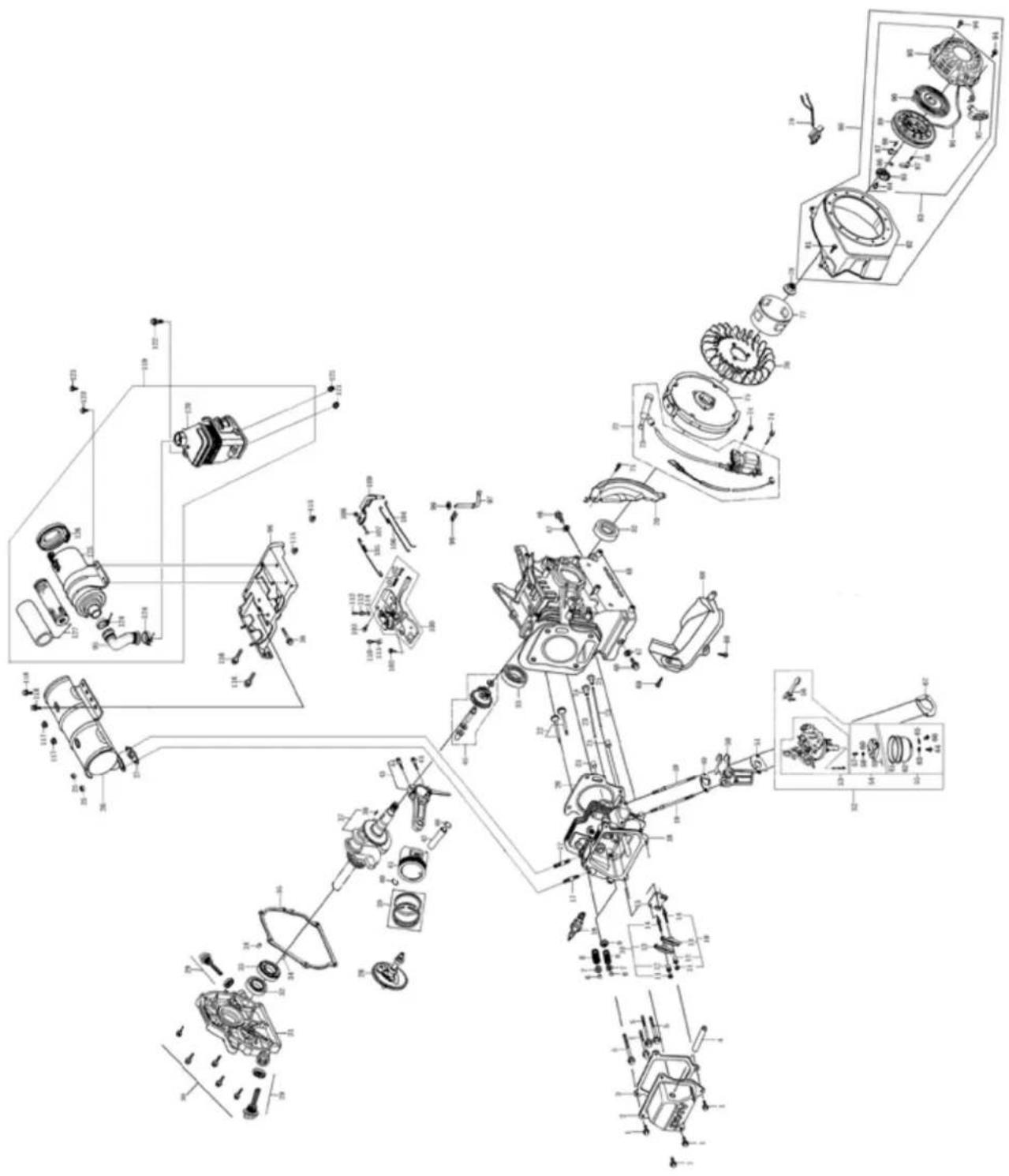
text_image
Exploded view diagram of a mechanical assembly with labeled components and exploded viewsEC Declaration of Conformity
Translation of the original EC declaration of conformity
Standard references:
EN 55012; EN 61000-6-1; EN 500-1; EN 500-4; EN ISO 3744
This declaration of conformity is issued under the sole responsibility of the manufacturer.
Subject to change without notice
Documents registrar: Tobias Ihle
Günzburger Str. 69, D-89335 Ichenhausen
CE
SCHEPPACH GMBH
Günzburger Str. 69
D-89335 Ichenhausen


FSC
www.fsc.org
MIX
Paper from responsible sources
C109124

FSC
www.fsc.org
MIXTE