
PBRM 46 A1 - Lawn mower PARKSIDE - Free user manual and instructions
Find the device manual for free PBRM 46 A1 PARKSIDE in PDF.


| Product type | Gas lawn mower with electric starter |
| Brand | Parkside |
| Model | PBRM 46 A1 |
| Cutting width | 46 cm |
| Cutting heights | 25 - 75 mm (8 levels) |
| Grass catcher capacity | 50 L |
| Engine type | 4-stroke, air-cooled, 150 cm³ |
| Engine power | 2.6 kW (3.5 HP) at 3600 min⁻¹ |
| Fuel | Unleaded petrol (max 10% bioethanol), 1 L tank |
| Engine oil | SAE 10W-30 or SAE 10W-40, capacity 0.4 L |
| Electric starter power supply | 20 V lithium-ion battery (Parkside X 20 V TEAM series) |
| Weight (assembled, empty tank) | 28.7 kg |
| Functions | Mowing with bag, mulching, side discharge, rear wheel drive |
| Cutting height adjustment | Manual, 8-position lever |
| Safety system | Engine brake with blade stop in ≤7 s, restart protection |
| Sound level (guaranteed) | 96 dB(A) |
| Vibrations (handle) | 5.7 m/s² (uncertainty 2.3 m/s²) |
| Routine maintenance | Cleaning with water connection, oil change, air filter cleaning, blade replacement |
| Main wear parts | Blade, spark plug, air filter, V-belt |
| Warranty | 5 years (subject to conditions) |
Frequently Asked Questions - PBRM 46 A1 PARKSIDE
User questions about PBRM 46 A1 PARKSIDE
0 question about this device. Answer the ones you know or ask your own.
Ask a new question about this device
Download the instructions for your Lawn mower in PDF format for free! Find your manual PBRM 46 A1 - PARKSIDE and take your electronic device back in hand. On this page are published all the documents necessary for the use of your device. PBRM 46 A1 by PARKSIDE.
USER MANUAL PBRM 46 A1 PARKSIDE
natural_image
Line drawing of a lawn mower with visible frame, wheels, and mounting brackets (no text or symbols)
PETROL LAWNMOWER PPBRM 46 A1
BENZIN-RASENMÄHER PPBRM 46 A1
TONDEUSE À ESSENCE PPBRM 46 A1

PETROL LAWNMOWER
Operating and Safety Instructions
Translation of the original operating instructions

TONDEUSE À ESSENCE
Before reading, unfold the page with the illustrations and then familiarise yourself with all the functions of the product.
DE AT CH
GB / IE / NI / CY / MTOperating and Safety Instructions Page 1
1 Explanation of the symbols on the product.... 2
2 Introduction.... 3
3 Product description (Fig. 1-28).... 3
4 Scope of delivery (Fig. 1-2).... 3
5 Proper use 3
6 Safety instructions 4
7 Technical data 6
8 Unpacking.... 7
9 Assembly 7
10 Before commissioning 8
11 Start-up....9
12 Operation 9
13 Working instructions.... 11
14 Cleaning.... 11
15 Maintenance 12
16 Transport (fig. 1).... 14
17 Storage 14
18 Repair & ordering spare parts.... 15
19 Disposal and recycling.... 15
20 Troubleshooting.... 16
21 EU Declaration of Conformity 17
22 Warranty certificate.... 18
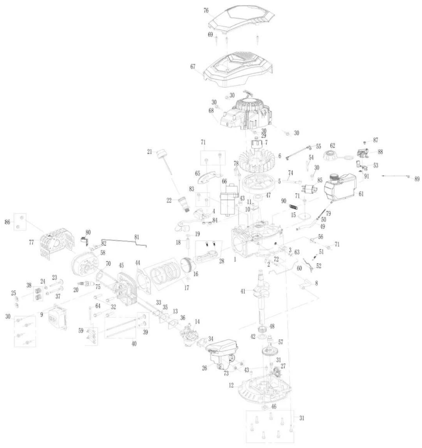
23 Exploded view 211
1 Explanation of the symbols on the product
Symbols are used in this manual to draw your attention to potential hazards. The safety symbols and the accompanying explanations must be fully understood. The warnings themselves will not rectify a hazard and cannot replace proper accident prevention measures.
 | Attention! Failure to observe the safety signs and warning information affixed to the product and failure to observe the safety and operating manual can result in serious injury or even death. |  | The motor becomes very hot during operation, do not touch! |
 | Before commissioning, read and observe the operating manual and safety instructions! |  | ATTENTION! Operating materials are flammable and explosive - danger of burning. Do not refuel while the engine is hot or running. |
 | Wear hearing protection. Wear safety goggles. | 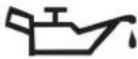 | Engine oil |
 | Make sure that other persons maintain a sufficient safety distance. | 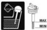 | Check the oil level. |
 | Do not mow uphill or downhill. Tank contents |  | |
 | Danger due to parts flying off while the engine is running. | 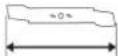 | Blade length. Max. cutting width. |
 | Keep your hands and feet away from the rotating blades. | 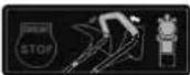 | DRIVE - Drive bow STOP - Engine brake lever |
 | Before operating the lawnmower, remove any small parts lying around that could be thrown about. |  | Remove the transport lock. |
 | Danger of poisoning! Only use the product outdoors and never in closed or poorly ventilated rooms. | 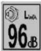 | Guaranteed sound power level of the product. |
 | Remove the spark plug connector prior to all maintenance work. |  | The product complies with the applicable European directives. |
2 Introduction
Manufacturer:
Scheppach GmbH
Günzburger Straße 69
D-89335 Ichenhausen
Dear Customer
We hope your new product brings you much enjoyment and success.
Note:
In accordance with the applicable product liability laws, the manufacturer of this product assumes no liability for damage to the product or caused by the product arising from:
- Improper handling
• Non-compliance with the operating manual
• Repairs carried out by third parties, unauthorised specialists
• Installing and replacing non-original spare parts - Improper use
- Failures of the electrical system in the event of the electrical regulations and VDE provisions 0100, DIN 57113 / VDE0113 not being observed.
Note:
The operating manual is part of this product.
It includes important instructions for the safe, proper and economic operation of the product, for avoiding danger, for minimising repair costs and downtimes and for increasing the reliability and extending the service life of the product. In addition to the safety instructions in this operating manual, you must also observe the regulations applicable to the operation of the product in your country.
Familiarise yourself with all operating and safety instructions before using the product. Only operate the product as described and for the specified areas of application. Keep the operating manual in a good place and hand over all documents when passing the product on to third parties.
3 Product description (Fig. 1-28)
- Steering
- Drive bow
2a. Bowden cable - Engine brake lever
3a. Accelerator cable - Electric starter
- Upper push bar
- Electric starter unit
- Quick release
7a. Spacer (quick release)
7b. Star grip screw (quick release)
7c. Threaded bush (quick release)
7d. Spacer disc (quick release) - Lower push bar
- Cable clip
- Guide (push bar)
- Fuel filler cap
- Fuel tank
- Air filter cover
13a. Air filter - Water connection
- Idler
-
Spark plug connector
16a. Spark plug -
Exhaust pipe
- Oil dipstick
- Side discharge flap
19a. Side discharge - Drive wheel
- Wing nut (lower push bar)
21a. M8 screw (wing nut)
21b. Spacer (wing nut) - Cutting height adjustment
- Discharge flap
- Grass collection basket
24a. Fill level indicator (grass collection basket) - Rope hook
- Pull starter
- Mulching insert
- Battery
28a. Battery unlocking lever
28b. Battery charge status indicator
28c. Button for battery charge status indicator - Battery charger
- Blade
- Blade screw
- Washer
- Engine spindle
- Carburettor screw
- V-belt
4 Scope of delivery (Fig. 1-2)
Item Quantity Designation
-
1 x Petrol lawnmower with upper push bar
-
2 x Quick release
7a. 2 x Spacer (quick release)
7b. 2 x Star grip screw (quick release)
7c. 2 x Threaded bush (quick release)
7d. 2 x Spacer disc (quick release)
-
1 x Lower push bar
-
1 x Cable clip
-
2 x Guide (push bar)
-
2 x Wing nut
21a. 2 x M8 screw (wing nut)
21b. 2 x Spacer (wing nut)
-
1 x Grass collection basket
-
1 x Mulching insert
-
1 x Battery
-
1 x Battery charger
A. 4 x Screws
B. 1 x Spark plug wrench
C. 2 x Velcro straps
2 x Operating instructions
(lawnmower, battery + battery charger)
5 Proper use
The petrol lawnmower is intended for private use i.e. for use in home and gardening environments. Private use of the lawnmower refers an annual operating time generally not exceeding that of 50 hours, during which time the machine is primarily used to maintain small-scale, residential lawns and home/hobby gardens. Public facilities, sporting halls, and agricultural/forestry applications are excluded.
The product may only be used in the intended manner. Any use beyond this is improper. The user, not the manufacturer, is responsible for damages or injuries of any type resulting from this.
An element of the intended use is also the observance of the safety instructions, as well as the assembly instructions and operating information in the operating manual.
Persons who operate and maintain the product must be familiar with the manual and must be informed about potential dangers.
The liability of the manufacturer and resulting damages are excluded in the event of modifications of the product.
The product may only be operated with original parts and original accessories from the manufacturer.
The safety, operating and maintenance specifications of the manufacturer, as well as the dimensions specified in the technical data, must be observed.
Please note that our products were not designed with the intention of use for commercial or industrial purposes. We assume no guarantee if the product is used in commercial or industrial applications, or for equivalent work.
Due to physical danger to the user, the lawnmower must not be used for the following work (incomplete list):
• for trimming bushes, hedges and shrubs,
• for cutting climbing plants,
- for lawn care on roof plantings and in balcony boxes,
- for chipping and shredding tree and hedge cuttings,
- for cleaning pavements (vacuuming, blowing away),
- for levelling ground elevations, such as molehills.
- for transporting cuttings, except in the grass collection basket provided.

WARNING
For your own safety, please thoroughly read this manual and the general safety instructions before turning the product on. If you give the product to third parties, always include these usage instructions.
The product is part of the Parkside X 20 V TEAM and can be operated using Parkside X 20 V TEAM range batteries. The batteries are permitted to be charged using the Parkside X 20 V TEAM range battery chargers.
Explanation of the signal words in the operating manual

DANGER
Signal word to indicate an imminently hazardous situation which, if not avoided, will result in death or serious injury.

WARNING
Signal word to indicate a potentially hazardous situation which, if not avoided, could result in death or serious injury.

CAUTION
Signal word to indicate a potentially hazardous situation which, if not avoided, could result in minor or moderate injury.
ATTENTION
Signal word to indicate a potentially hazardous situation which, if not avoided, could result in product or property damage.
6 Safety instructions
Keep all safety information and instructions for future reference!

WARNING
Read all safety warnings, instructions, illustrations and specifications provided with this product.
Failure to observe the following instructions can result in serious injuries.
Who is not permitted to use the product:
- Children and other people who do are not familiar with the usage instructions (local stipulations may specify a minimum age for users).
- People under the influence of alcohol, drugs and medication, as well as those who are tired or ill.
6.1 Safety instructions for hand-operated lawnmowers
- Read the usage instructions with due care. Familiarise yourself with the settings and proper operation of the product.
- Never allow children or other persons who are unfamiliar with the usage instructions to use the lawnmower. Contact your local governmental agency for information regarding minimum age requirements for operating the lawnmower.
- Never mow while people, especially children or animals are nearby. Always keep in mind that the operator is responsible for accidents involving other persons and/or their property.
- Only mow when visibility is good. It is necessary to keep third parties away.
- If you hand the product over to another person, please hand over this operating manual as well.
- Always wear sturdy, non-slip footwear and long trousers when mowing. Never mow barefoot or in sandals.
- Check the terrain on which the product will be used and remove all objects that could be caught up and violently flung out of the chute (like stones, toys, sticks and wires etc.).
- Switch off the engine, wait for it to stop and disconnect the spark plug connector if
- you are leaving the product.
- You are removing blockages or obstructions.
– the product has been in contact with foreign objects.
- malfunctions and unusual vibrations occur on the product.

WARNING
Fuel is highly flammable:
- Only store fuel in containers (canisters) designed for this purpose.
- Refuel outdoors only and do not smoke while refuelling.
-
Fuel must be filled before starting the engine. While the engine is running or immediately after switching off the product, do not open the fuel filler cap or add fuel.
-
If fuel overflows, no attempts should be made to start the engine. Instead, the product must be removed from the area contaminated with fuel. Do not try to start the engine until the fuel vapours have evaporated.
- For safety reasons, the fuel tanks and other fuel caps must be replaced if damaged.
- Never store fuel near a source of sparks. Always use a tested canister. Keep fuel away from children.
- Replace defective silencers.
- Prior to use. always perform a visual inspection to check whether the blade and fastening bolts are worn out or damaged. To prevent an imbalance, worn out or damaged blades and bolts may only be replaced in sets.
6.2 Electrical safety
- The connection plug of the electric tool must fit into the socket. Never modify the plug in any way. Do not use any adapter plugs with earthed (grounded) power tools. Unmodified plugs and matching outlets will reduce risk of electric shock.
- Avoid body contact with earthed or grounded surfaces, such as pipes, radiators, ranges and refrigerators. There is an increased risk of electric shock if your body is earthed or grounded.
- Do not expose power tools to rain or wet conditions. Water entering a power tool will increase the risk of electric shock.
Follow the safety instructions. and the notes regarding charging and correct use, as specified in the operating manual for your Parkside X 20 V Team range battery and battery charger.
A detailed description of the charging process and further information are provided in this separate operating manual.
Incorrect use of the battery or battery charger can cause electric shock or fire.
6.3 Handling
Handling:
- Make sure that all nuts, bolts and screws are securely tightened so that the product is kept in a safe working condition.
- Never store the product with fuel in the tank inside a building in which fuel vapours may come into contact with naked flames or sparks.
- Allow the engine to cool down before parking the product in enclosed spaces.
- In order to avoid fire hazards, keep the engine, exhaust pipe and the area around the fuel tank free of grass, leaves and leaking grease (oil).
- Regularly check the catch basket for signs of wear and loss of functionality.
- For safety reasons, replace worn or damaged parts.
- If the fuel tank has to be drained, you must do this outdoors.
- Do not run the combustion engine in closed rooms in which hazardous carbon monoxide can collect.
- Only mow in daylight or with good artificial lighting.
- Avoid using the product on wet grass as far as possible.
- Do not use the product in a thunderstorm - Danger of lightning strike!
• Always maintain good footing on inclines.
- Only guide the product at walking pace.
- The following applies to wheeled products: Always mow across hills i.e. never straight up or straight down. Take particular care when changing direction on a slope.
- Do not mow on excessively steep slopes and nearby rubbish tips, ditches and dykes. Take particular care when reversing the product or pulling it towards you.
- Stop the blade when the lawnmower has to be tilted, when transporting over areas other than grass and when moving the lawnmower to and from the area to be mowed.
CAUTION
The lawnmower must not be used without either the full grass catcher or the self-closing separating guard for the ejection opening in place.
- Never use the lawnmower if the blade or safety grilles are damaged, or without the attached guards, e.g. deflectors and/or grass catching devices.
- Do not adjust and overclock the engine speed settings.
- Release the engine brake and disengage all cutting tools and drives before starting the engine.
- Start the engine with care, in accordance with the manufacturers instructions. Ensure that your feet are far enough away from the blade.
- Do not tip the lawnmower when you start the engine unless the lawnmower must be raised off of the ground a little in order to start it. In this case, only tilt as far as absolutely required and only lift the side away from the operator.
- Do not start the engine if you are standing in front of the ejector chute.
- Never put hands and feet on or under rotating parts. Always keep clear of the ejection opening.
- Never lift or carry a lawnmower while the engine is running.
- Stop the engine and make sure that all moving parts have come to a standstill and that the ignition key, if present, is removed:
- Before you dislodge any blockages or clogs in the ejector chute.
- Before checking or cleaning the product, or performing work on it.
- If it came into contact with a foreign object. Inspect the product for damage and perform the required repairs before starting again and working with the product. If the product begins to experience exceptionally strong vibrations, switch it off immediately and check it.
– Any time you leave the product. - Before you refuel.
- When the engine runs out, close the throttle valve. If the engine has a petrol shut-off valve, close it after use.
- Operating the product at excessive speed can increase the risk of accidents.
-
Be careful when adjusting the product and avoid trapping fingers between the moving blade and rigid parts of the device.
-
Be particularly careful when mowing on yielding ground, nearby rubbish tips, ditches and dykes.
- Avoid mowing in places where the wheels have trouble gripping or mowing is unsafe in any other way.
- Watch out for traffic near a road.

DANGER
Risk of tripping!
Exercise particular caution when moving backwards and pulling the product.
Before reversing, make sure there are no small children behind you.
- The user must be adequately trained in the use, adjustment and operation of the machine (including prohibited operations).
- Check the product regularly and make sure that all start locks and push buttons are working properly before each use.
- Please note that improper maintenance, the use of non-compliant spare parts, or the removal or modification of safety devices can result in damage to the product and serious injury to the person working with it.
- Please note that the product's safety systems or equipment must not be tampered with or deactivated. Never remove any safety-related parts.
- Please note that the user must not change or manipulate any sealed engine speed control settings.
- Use only blades and accessories recommended by the manufacturer. Use of other insert tools and accessories may result in injury to the user.
- Always keep the product in good operating condition.
- It is necessary to take enough breaks to reduce noise and vibration exposure.
6.4 Residual risks and protective measures
Neglect of ergonomic principles
Negligent use of personal protective equipment (PPE)
Careless use or omission of personal protective equipment may result in serious injury.
- Wear prescribed protective equipment.
Human behaviour, misconduct
• Always concentrate fully on all work.
Residual danger
- Can never be ruled out
Danger from noise
Hearing damage
Prolonged unprotected work with the product may cause hearing damage.
• Always wear hearing protection as a matter of principle.
Behaviour in an emergency
In the event of an accident, initiate the necessary first aid measures and seek medical assistance as quickly as possible.
6.5 Residual risks
The product has been built according to state-of-the-art and the recognised technical safety rules. However, individual residual risks can arise during operation.
• Furthermore, despite all precautions having been met, some non-obvious residual risks may still remain.
- Residual risks can be minimised if the "Safety Instructions" and the "Intended Use" together with the operating manual as a whole are observed.
- Prevent the product being unintentionally started up.
- Keep your hands away from the working area when the product is in operation.
- Unintentional starting up of the product.
- Comply with the stipulated maintenance and safety instructions in the operating manual.
7 Technical data
| Type of motor 4-stroke engine/air-cooled | |
| Displacement 150 cm3 | |
| Rotation speed 2800 rpm | |
| Max. speed 3600 rpm | |
| Engine output 2.6 kW / 3.5 PS (3600 rpm) | |
| Fuel Regular grade petrol/lead-free max. 10% bioethanol | |
| Tank contents | 1 l |
| Engine oil | SAE 10W-30/SAE 10W-40 |
| Oil tank capacity | 0.4 l |
| Cutting height adjustment | 25-75 mm/8 stages |
| Cut heights 25 (1) / 35 (2) / 45 (3) / 50 (4) /55 (5) / 65 (6) / 70 (7) / 75 (8)(+ / - 5) mm | |
| Grass collection basket capacity | 50 l |
| Cutting width | 46 cm |
| Weight (with empty tank and fully assembled) | 28.7 kg |
Subject to technical changes!
Rechargeable battery / battery charger
The technical data for the rechargeable battery and battery charger can be found in the accompanying operating manual.
ATTENTION
The product is part of the Parkside X 20 V TEAM and can be operated using Parkside X 20 V TEAM range batteries. The batteries are permitted to be charged using the Parkside X 20 V TEAM range battery chargers.
Noise and vibration

WARNING
Noise can have serious effects on your health. If the machine noise exceeds 85 dB, please wear suitable hearing protection for you and persons in the vicinity.
Noise data
| Sound pressure level L_pA | 74.6 dB |
| Measurement uncertainty K_pA | 1.81 dB |
| Measured sound power level L_wA | 94.6 dB |
| Guaranteed sound power level L_wA | 96 dB |
| Measurement uncertainty K_wA | 1.81 dB |
If necessary, adhere to rest periods and limit the duration of work to the bare minimum.
Vibration parameters (hand/arm vibration)
| Vibration a_hv | 5.7 m/s ^2 |
| Measurement uncertainty K_h | 2.3 m/s ^2 |
Keep the noise level and vibration to a minimum!
- Only use faultless products.
- Adapt your working methods to the product.
- Do not overload the product.
- Have the product checked if necessary.
- Switch the product off if it is not in use.
- Wear gloves.
- Maintain and clean the product at regular intervals.

WARNING
In case of extended working periods, the operating personnel may suffer circulatory disturbances in their hands (vibration white finger) due to vibrations.
Raynaud's syndrome is a vascular disease that causes the small blood vessels on the fingers and toes to cramp in spasms. The affected areas are no longer supplied with sufficient blood and therefore appear extremely pale. The frequent use of vibrating products can cause nerve damage in people whose circulation is impaired (e.g. smokers, diabetics).
If you notice unusual adverse effects, stop working immediately and seek medical advice.
Observe the following information to reduce hazards:
- Keep your body and especially your hands warm in cold weather.
• Take regular breaks and move your hands to promote circulation. - Ensure as little vibration as possible of the product via regular maintenance and stable parts on the product.
8 Unpacking

WARNING
The product and the packaging material are not children's toys!
Do not let children play with plastic bags, films or small parts! There is a danger of choking or suffocating!
- Open the packaging and carefully remove the product.
- Remove the packaging material, as well as the packaging and transport safety devices (if present).
-
Check whether the scope of delivery is complete.
-
Check the product and accessory parts for transport damage. Immediately report any damage to the transport company that delivered the Product. Later claims will not be recognised.
- If possible, keep the packaging until the expiry of the warranty period.
- Familiarise yourself with the product by means of the operating manual before using for the first time.
- With accessories as well as wearing parts and replacement parts use only original parts. Spare parts can be obtained from your specialist dealer.
- When ordering please provide our article number as well as type and year of manufacture for the product.
9 Assembly

CAUTION
Danger of injury due to rotating blade. Only work on the product when the blade is switched off and stationary!
ATTENTION
Ensure that the throttle cable is not squeezed when mounting the push bars.
Place the product on a level, even surface.
Tool required:
- Phillips screwdriver*
* = may not be included in the scope of delivery!
9.1 Installation of the lower push bar (8) (Fig. 3, 4)
- Detach the component from the M8 screw (21a), spacer (21b) and wing nut (21).
- Push one guide (10) each onto the bolt on the lower push bar (8).
- Place the lower push bar (8) on the guides (10). Make sure that the lower push bar (8) is seated in the bolt and that the fastening holes are aligned.
- Insert one M8 screw (21a) through each of the fastening holes of the lower push bar (8).
- Place a spacer (21b) on each M8 mm screw (21a) and secure them with a plastic star nut (21).
9.2 Installation of the upper push bar (5) (Fig. 1, 5, 6)
- Unscrew the star grip screws (7b) including the spacers (7a) and spacer disc (7d) from the threaded bush (7c).
- Align the upper push bar (5) with the corresponding attachment points of the lower push bar (8).
- Place a spacer disc (7d) on each star grip screw (7b) and insert it through the fastening holes of the upper and lower push bar (5+8).
- Place a spacer (7a) on each star grip screw (7b).
- Secure the star grip screws (7b) with the quick releases (7). Make sure that the throttle cable (3a) and the Bowden cable (2a), which will later be attached with a cable clip (9), are not in the way.
9.3 Fitting the electric starter unit (6) (Fig. 1, 7-11)
- Press the right-hand side of the engine brake lever (3) out of the plastic holder on the upper push bar (5).
- Move the engine brake lever (3) forward to release it from the plastic holder.
- Place the electric start unit (6) on the upper push bar (5).
- Use the screws (A) to secure the electric starter unit (6). Make sure that the throttle cable (3a) and the Bowden cable (2a), which will later be attached with a cable clip (9), are not in the way.
- Use a Phillips screwdriver to tighten the screws (A).
- Use two velcro straps (C) to fasten the electric starter unit (6) cable to the lower push bar (8).
- Pull the throttle cable (3a) through the electric starter unit (6) as shown in Fig. 8.
- Insert the throttle cable (3a) into the engine brake lever (3) and press the right-hand side of the engine brake lever (3) back into the plastic holder on the upper push bar (5).
- Fix the throttle cable (3a) and the Bowden cable (2a) to the lower push bar (8) using the cable clip (9) provided.
- Hook the handle of the pull starter (26) into the cable hook (25).
10 Before commissioning
ATTENTION
Always make sure the product is fully assembled before commissioning!

WARNING
Health hazard!
Inhalation of fuel / lubricating oil vapours and exhaust gases can cause serious damage to health, unconsciousness and in extreme cases death.
- Do not breathe fuel / lubricating oil vapours and exhaust gases.
- Operate the product outdoors only.
ATTENTION
Product damage!
Using the product without or with too little engine and gear oil can result in engine damage.
- Fill with fuel and oil before commissioning. The product is supplied without engine and gearbox oil.
ATTENTION
Environmental damage!
Spilled oil can pollute the environment permanently. The liquid is highly toxic and can quickly lead to water pollution.
– Fill/empty oil only on level, paved surfaces.
- Use a filling nozzle or funnel.
- Collect drained oil in a suitable container.
- Wipe up spilled oil carefully immediately and dispose of the cloth according to local regulations.
– Dispose of oil as per local regulations.
ATTENTION
Risk of damage!
If incorrectly stored or undrained fuel is used, the carburettor may become clogged or engine operation may be affected.
- Put unused fuel in an airtight vessel and store it in a dark, cool room.
Place the product on a level, even surface.
Tool required:
- 1 litre measuring beaker (oil / petrol-proof)*
- Funnel*
- Cloth*
* = may not be included in the scope of delivery!
10.1 Filling up with engine oil (Fig. 12)
ATTENTION
The product is delivered without engine oil. Therefore, ensure that you add oil before starting it up. Use multigrade oil (SAE 10W-30 or 10W-40) for this.
Check the oil level regularly before commissioning. An oil level that is too low can damage the motor.
- Unscrew the oil dipstick (18).
- Fill the tank with engine oil using a funnel. Note the max. filling capacity of 0.4 l. Fill the oil up to the lower edge of the filling nozzle carefully.
- Wipe the oil dipstick (18) with a clean, lint-free cloth.
- Re-insert the oil dipstick (18) and pull it out again. Check the oil level without screwing the oil dipstick (18) back in.
- The oil level must be within the middle mark on the oil dipstick (18).
- If the oil level is too low, add the recommended amount of oil (max. 0.4 l).
- Then screw the oil dipstick (18) in again.
10.2 Filling up with fuel (Fig. 13)
DANGER
Risk of fire and explosion!
When filling, fuel may ignite and even explode. This can lead to severe burns or death.
- Switch off the engine and let it cool down.
- Keep heat, flames and sparks away.
- Only fill up with fuel outdoors.
- Wear protective gloves.
- Avoid contact with skin and eyes.
- Start the product at a distance of at least 3 m from the fuel filling point.
- Watch out for leaks. If fuel is leaking, do not start the engine.
ATTENTION
The product is delivered without fuel. It is therefore essential to fill with fuel before commissioning. Use Super E10 petrol for this.
- Clean the area surrounding the filling area. Impurities in the fuel tank (12) lead to operational faults.
- Carefully open the tank cover (11) so that any possible overpressure can be relieved.
- Fill the fuel tank (12) with petrol using a funnel. Note the max. filling capacity of 1 l. Fill the petrol up to the lower edge of the filling nozzle carefully.
- Close the tank cover (11) again. Ensure that the fuel filler cap (11) is tightly sealed.
- Clean the tank cover (11) and the surroundings.
10.3 Charge status of the battery (28) (Fig. 1, 14)
The lawnmower is equipped with an electric starter (4). A lithium ion battery (28) is used as the starter battery. Using the battery (28) and the battery charger (29) is described in the user manual supplied.
- To check the charge status, press the charge status indicator button (28c) on the battery (28). The battery charge status indicator (28b) indicates the charge status of the battery (28).
- The battery (28) may only be charged using the battery charger (29) supplied. The battery (28) is not recharged when operating the lawnmower.
11 Start-up
NOTE
Some noise pollution from this product is unavoidable. Postpone noisy work to approved and designated times. If necessary, adhere to rest periods and limit the duration of work to the bare minimum.
For your personal protection and the protection of nearby persons, wear suitable hearing protection.
11.1 Setting the cutting height (Fig. 15)
ATTENTION
Adjust the cutting height only when the engine is switched off and the plug boot has been pulled.
- In dense, tall grass, set the highest cutting level and mow more slowly. A high cutting height should be selected for the first cut of the season. Adjust the cutting height so that the product is not overloaded.
- Set the cutting height depending on the actual length of the lawn.
- Carry out several passes so that a maximum of 4 cm of lawn is removed at a time.
- The correct cutting height for
- ornamental grass is about 30mm - 45mm - utility turf about 40mm - 65mm .
The cutting height is adjusted via the cutting height adjustment lever (22). Different cutting heights can be set.
- Pull the cutting height adjustment lever (22) outwards.
- Slide the cutting height adjustment lever (22) to the desired cut height position.
- Release the cutting height adjustment lever (22) again. The lever locks into the desired position.
11.2 Inserting/removing the battery (28) (Fig. 16)
- To remove the battery (28) from the product, press the battery unlocking lever (28a) on the battery (28) and pull the battery (28) out.
- To insert the battery (28), push the battery (28) along the guide rail into the electric starter unit (6). It clicks into place audibly.
11.3 Blade-stop device (Fig. 1, 24)
Before each use, you must check the blade stop device. Start the engine as described in 12.4.
- Release the engine brake lever (3). The engine switches off and the blade (30) is braked.
- The blade (30) must stop within 7 seconds.
11.4 Preparing the area to be mowed
- Before mowing, carefully examine the area.
- Remove stones, sticks, bones, wires, toys and other objects that may be ejected by the product.
- Ensure that no other people are present on the surface to be mowed.
12 Operation
The lawn mower is powered by a powerful, air-cooled 4-stroke engine.
The product can be started with or without an electric starter unit and is equipped with an 8-position cutting height adjustment, a grass catcher and a foldable push bar.
Please refer to the following descriptions for the function of the controls.
Check before operation
- Check all sides of the engine for oil or fuel leaks.
- Check the engine oil level.
- Check the fuel level – the fuel tank should be at least half-full.
- Check the condition of the air filter.
- Check the condition of the fuel lines.
- Make sure that the spark plug connector is attached to the spark plug.
- Look for signs of damage.
- Check that all protective covers are in place and all screws, nuts and bolts are tightened.
12.1 Mowing with the grass collection basket
ATTENTION
Do not operate the product without the grass collection basket fully attached or without a mulching insert.
ATTENTION
Only remove or attach the grass collection basket when the engine is switched off and the blade is stationary.
12.1.1 Inserting the grass collection basket (24) (Fig. 17)
- Lift the rear discharge flap (23).
- Hold the grass collection basket (24) by the carrying handle.
- Hang the grass collection basket (24) in the grass collection basket suspension provided at the rear of the product.
- Put down the rear discharge flap (23), it holds the grass collection basket (24) in position.
12.1.2 Level indicator (24a) on the grass collection basket (24) (Fig. 17)
The air flow generated by the blade (30) lifts the level indicator (24a). When the grass collection basket (24) is full, the air flow stops. If the air flow is too low, the level indicator (24a) closes. This is a note to empty the grass collection basket (24).
The unrestricted function of the level indicator (24a) is only assured with optimum air flow. External influences such as wet, dense or high grass, low cutting levels, dirt or similar can affect the air flow and the function of the level indicator (24a).
- Flap open: Grass collection basket (24) is being filled
- Flap closed: Grass collection basket (24) is full
12.1.3 Emptying the grass collection basket (24) (Fig. 1, 17)

WARNING
Before removing the grass collection basket, switch off the engine and wait for the blade to stop.
ATTENTION
Danger of injury!
Remove the grass collection basket only when the engine is switched off and the blade is stationary.
The grass collection basket must be emptied as soon as grass cuttings are left lying behind on the ground during mowing.
- To remove the grass collection basket (24), lift the rear discharge flap (23).
- Take out the grass collection basket (24) by the carrying handle. In accordance with the safety regulations, the discharge flap (23) closes when the grass collection basket (24) is unhooked and closes the rear ejection opening.
If grass cuttings remain in the opening, it is advisable to pull the lawnmower back about 1m to make it easier to start the engine.
ATTENTION
Do not remove cuttings in the mower housing and on the working tool by hand or with your feet, but with suitable aids, e.g. brush or hand brush.
To ensure good collection, the grass collection basket (24) and in particular the air filter (13a) must be cleaned from the inside after use.
12.2 Mowing with side discharge
The side discharge (19a) enables you to even manage high and wild grass that is only mown rarely.
12.2.1 Inserting the side discharge (19a) (Fig. 18)
- First remove the grass collection basket (24) and insert the mulching insert (27) (see 12.3).
- Open the side discharge flap (19) and hold it tight.
- Insert the side discharge (19a).
- Close the side discharge flap (19) slowly. The side discharge flap (19) secures the side discharge (19a) to prevent it falling out.
12.2.2 Removing the side discharge (19a) (Fig. 18)
- Open the side discharge flap (19) and hold it tight.
- Remove the side discharge (19a) and close the side discharge flap (19).
12.3 Mowing with the mulching insert
When mulching, the cuttings are shredded in the closed mower housing and then dispersed on the lawn. Grass collection and disposal are not required. The fine green waste falls back into the grass root as a natural fertiliser, adds moisture to the lawn and supplies it with important nutrients.
NOTE
Mulching is only possible on relatively short lawns.
12.3.1 Inserting the mulching insert (27) (Fig. 19)
- Lift the rear discharge flap (23).
- Remove the grass collection basket (24) (if used) by the carrying handle.
- Lift the discharge flap (23) and insert the mulching insert (27).
- Adjust the cut height (see. 11.1).
Tips for mulching and mowing:
- Cut the grass back by 2 cm if the grass is 4-6 cm high.
12.4 Starting the engine
NOTE
The blade rotates when the engine is started.
Do not start the product if the ejector chute is covered by one of the following parts:
- Grass collection basket
- Mulching insert
12.4.1 Using the electric starter to start the engine (Fig. 1, 20)
- Check the charge status of the battery (28) (see 10.3) and charge it if required.
- Check the fuel and engine oil levels before each start (see sections 10.1 and 10.2). Make sure that the spark plug connector (16) is connected to the spark plug (16a).
- Slide the charged battery (28) along the guide rail into the product. The battery (28) clicks into place audibly.
- Stand behind the lawnmower.
-
Press the engine brake lever (3) to the steering (1) and hold it.
-
Press the electric starter (4) on the electric starter unit (6) and hold it.
- The engine will start.
- Once the engine has started, let go of the electric starter (4).
12.4.2 Starting the engine without the electric starter (Fig. 1, 21)
- Check the fuel and engine oil levels before each start (see sections 10.1 and 10.2). Make sure that the spark plug connector (16) is connected to the spark plug (16a).
- Stand behind the lawnmower. One hand pushes the engine brake lever (3) to the steering (1), the other pulls the pull starter (26).
- Start the engine with the pull starter (26). To do this, pull the handle out approx. 10-15 cm (until resistance is felt). And then pull hard with a jerk. If the engine does not start, pull on the pull starter (26) again.
- Due to protective coating on the engine, a small amount of smoke may be present during the initial use of the product and should be considered normal. This is a normal process.
ATTENTION
- Do not let the pull starter whip back in. This can result in damage.
– In case of cool weather, it may be necessary to repeat the starting process numerous times.
12.5 Driving mode (Fig. 1)
The lawnmower is equipped with a rear-wheel drive.
12.5.1 Switching the drive on
- Start the lawnmower (see 12.4).
- Pull and hold the drive bow (2) to the steering (1).
- The drive is switched on (the wheel (15) moves) and the lawnmower starts to move forwards.
ATTENTION
Avoid damage to the product! Avoid damage to the product! Always operate the drive bow completely (until it reaches the stop) to avoid consequential damage to the transmission.
12.5.2 Switching the drive off
- Release the drive bow (2). The drive is switched off and the lawnmower stops.
- The engine continues to run.
12.6 Shut off engine
WARNING
Danger of injury!
After switching the engine off, the blade continues to run for a few seconds. If you touch the rotating parts, you may cut yourself.
- Only cut with sharp, flawless mowing blades so that the blades of grass do not fray and the lawn does not turn yellow.
- To achieve a clean cut, guide the lawnmower in the straightest possible paths. These strips should always overlap by a few centimetres so that no patches remain.
- Keep the underside of the mower housing clean and be sure to remove grass debris. Deposits make the starting process more difficult, impair cutting quality and grass discharge.
- On slopes, the cutting path should be made perpendicular to the slope. It is possible to prevent the lawnmower from slipping by lifting it upwards at an angle.
13.1 After mowing
- Always allow the engine to cool down before parking the lawnmower in an enclosed space. Remove grass, leaves, grease, and oil before storage. Do not store other objects on the lawnmower.
- Check all screws and nuts before the next use. Tighten up loose screws.
- Empty the grass collection basket before the next use.
- Please also observe the chapter "Storage".
14 Cleaning
WARNING
Danger of injury and burning!
The product can start unexpectedly and cause injuries.
- Switch off the motor before carrying out any cleaning or maintenance work.
- Allow the motor to cool down.
- Disconnect the spark plug connector from the spark plug.
- Remove the battery.
WARNING
Health hazard!
Inhalation of fuel / lubricating oil vapours and exhaust gases can cause serious damage to health, unconsciousness and in extreme cases death.
- Do not breathe fuel / lubricating oil vapours and exhaust gases.
- Operate the product outdoors only.
Tool required:
- Spatula*
- Hand brush*
- Compressed air*
* = may not be included in the scope of delivery!
14.1 Cleaning the lawnmower (Fig. 1)
- Cleaning with a garden hose is only recommended at low pressure. A high-pressure cleaner is not suitable for cleaning the product.
- Unhook the grass collection basket and brush it out with a hand brush. You can also roughly clean the housing of the lawnmower with the sweeper.
- For larger soiling, you can wipe the product with a damp Cloths.
NOTE
Before tilting the lawnmower, empty the fuel tank fully using a fuel extraction pump (not included in the scope of delivery).
Do not tilt the lawnmower beyond 90 degrees.
- It is best to tilt the lawnmower backwards. Make sure that the spark plug (16a) is pointing upwards. If the spark plug (16a) points downwards, oil can leak out and cause major damage to the engine and carburettor.
- Alternatively, you can tilt the product on its side, but you must make sure that the air filter cover (13) is on the upper side.
- Clean the underside of the lawnmower with a spatula and hand brush. The spatula helps to remove coarse and larger plant debris from the area of the blade (30). Cleaning the underbody is easier and more thorough immediately after use. Then dirt and plant residues are still fresh and can be loosened more easily.
- If necessary and if the dirt is difficult to remove, you can also use a special cleaner. Do not use aggressive cleaning products such as cold cleaners or white spirit.
- Check that the grass ejection is clear of grass residues and remove these if necessary.
14.2 Cleaning the lawnmower via the water connection (14) (Fig. 1, 22)
NOTE
Push the spark plug connector onto the spark plug properly again.
- First remove the mulching insert (27) or the grass collection basket (24).
- For cleaning, connect a garden hose to the water connection (14) via the built-in plug-in coupling.
- Turn on the water and start the lawnmower (see12.4).
- The rotating blade (30) swirls the water.
- After a few minutes, the lawnmower is free of all adhering dirt and grass residues.
- Allow the lawnmower to run for a short time without water to remove most of the moisture through the circulating air of the blade (30).
14.3 Cleaning the V-belt (35) (Fig. 23)
- Tilt the lawnmower backwards.
- Use a hand brush or compressed air to clean the V-belt (35) after each use.
15 Maintenance
WARNING
Have maintenance and repair tasks that are not described in this operating manual, carried out by a specialist workshop. Use only original spare parts.
There is a risk of accident! Always carry out maintenance and cleaning work when the engine is switched off. There is a danger of injury! Let the Product cool down before all maintenance and cleaning tasks. Elements of the engine are hot. There is a danger of injury and burning!
The product can start unexpectedly and cause injuries.
- Switch off the engine before carrying out any cleaning or maintenance work.
- Disconnect the spark plug connector from the spark plug.
- Allow the engine to cool down.
-
Remove the battery.
-
Regular, careful servicing is required to guarantee the safety level and performance of the product.
- Ensure that all nuts, pins and screws are securely tightened so that the product is in a safe working condition.
- Check the grass collection basket regularly for signs of wear and loss of functionality.
- For safety reasons, replace worn or damaged parts.
- Check that the front and rear wheels are secured.
- To ensure smooth running of the wheels, we recommend cleaning the wheel axles and wheel hubs at least once per season.
- Any work not described in this operating manual must be performed by an authorised specialist workshop only.
- Place the product on a level, even surface.
Tool required:
- Spark plug wrench (B)
- Fuel extraction pump*
- Cloth*
- Open-ended spanner/socket spanner, size 17 mm*
- Open-ended spanner/socket spanner, size 10 mm*
- Oil pump*
- Oil collecting tray, flat (for oil change)*
- Collection bucket*
- Copper wire brush*
- Torque wrench*
- Feeler gauge*
* = may not be included in the scope of delivery!
15.1 Changing the blade (30) (Fig. 24)
WARNING
There is a risk of injury if you work with a damaged blade.
- Wear protective gloves!
- For safety reasons you should only ever have your blade sharpened and balanced by an authorised specialist workshop. For optimum results it is recommended that the blade should be inspected once a year.
-
When changing the blade, only use original spare parts.
-
Empty the fuel tank (12) with a fuel extraction pump before removing the cutting edge. Never tip the lawnmower to the side or forwards with a full fuel or oil tank! This will damage the engine and void the warranty.
- Hold the blade (30) tightly with one hand.
- Turn the blade screw (31) anticlockwise using a open-end spanner AF17 from the engine spindle (33). Remove the washer (32).
- Re-install the new blade (30) in reverse order. Fasten the blade screw (31) properly. Make sure that the blade (30) is correctly positioned and flush against the engine spindle (33).
- The tightening torque of the blade screw (31) is 45Nm. Also replace the blade screw (31) when replacing the blade (30).
15.1.1 Damaged blades (30)
Should the blade (30) come into contact with an obstruction, shut down the engine immediately and remove the spark plug connector (16).
- Check the blade (30) for damage.
- Damaged or bent blades (30) must be replaced.
- Never attempt to bend a bent blade (30) back to straight again.
- Never mow the lawn with a bent or heavily worn blade (30) as this will cause vibrations and can lead to further damage to the lawnmower.
15.2 Checking the oil level (Fig. 12)
WARNING
Health hazard!
Inhalation of fuel / lubricating oil vapours and exhaust gases can cause serious damage to health, unconsciousness and in extreme cases death.
- Do not breathe fuel / lubricating oil vapours and exhaust gases.
- Operate the product outdoors only.
ATTENTION
Product damage!
Using the product without or with too little engine and gear oil can result in engine damage.
- Fill with fuel and oil before commissioning. The product is supplied without engine and gearbox oil.
- Only use SAE 10W-30 or SAE 10W-40 engine oil.
ATTENTION
Environmental damage!
Spilled oil can pollute the environment permanently. The liquid is highly toxic and can quickly lead to water pollution.
– Fill/empty oil only on level, paved surfaces.
– Use a filling nozzle or funnel.
– Collect drained oil in a suitable container.
- Wipe up spilled oil carefully immediately and dispose of the cloth according to local regulations.
– Dispose of oil as per local regulations.
- Turn the oil dipstick (18) anticlockwise to unscrew it and wipe it with a clean, lint-free cloth.
- Reinsert the oil dipstick (18) and check the oil level without screwing the oil dipstick (18) tight again.
- Pull the oil dipstick (18) out and read off the oil level. The oil level must be positioned between the max. and min. of the oil dipstick (18).
- Then screw the oil dipstick (18) in again.
15.3 Oil change (Fig. 12)
The engine oil change should be completed annually before the start of the season while the engine is at operating temperature and shut off.
Only use engine oil (SAE 10W-30/SAE 10W-40).
- Unscrew the oil dipstick (18) by turning it anticlockwise.
- Suck out the engine oil through the filler neck using an oil pump (with hose).
- Fill up with fresh engine oil and check the oil level (see 10.1).
15.4 Drain fuel with a fuel extraction pump (Fig. 25)
- Hold a collection bucket under the hose on the fuel extraction pump.
- Unscrew and remove the fuel filler cap (11).
- Push the hose of the fuel extraction pump into the fuel tank (12) and drain out the fuel tank completely using the fuel extraction pump.
- Retighten the fuel filler cap (11).
- To ensure that no fuel remains in the carburettor, the remaining fuel must be drained out of the carburettor. To do this, place a collection bucket under the carburettor and open the carburettor screw (34) with the aid of an open-end wrench AF10.
15.5 Maintenance of the air filter (13a) (Fig. 26)
DANGER
Risk of fire and explosion!
If not cleaned correctly, fuel may ignite and even explode. This can lead to severe burns or death.
- Only clean the air filter by knocking it out.
- Never clean the air filter with petrol or flammable solvents.
ATTENTION
Risk of damage!
Operating the engine without a filter element or with a damaged filter element can cause engine damage.
- Never run the engine without the air filter element or with a damaged filter element. This would allow dirt into the engine, which would result in severe damage to the engine.
Fouled air filters (13a) diminish the engine output due to reduced air supply to the carburettor. Regular inspection is therefore essential.
The air filter (13a) should be checked every 25 operating hours and cleaned as required. The air filter (13a) must be checked more often in case of very dusty air.
- Take off the air filter cover (13) and remove the air filter (13a).
- Clean the air filter (13a) only by knocking it out.
- Replace a defective air filter (13a) with a new one.
- Put the air filter (13a) back in place and replace the air filter cover (13).
15.6 Maintaining the spark plug (16a) (Fig. 27+28)
Check the spark plug (16a) for contamination for the first time after 10 operating hours and clean it with a copper wire brush if necessary. Then maintain the spark plug (16a) every 50 operating hours.
- Pull off the spark plug connector (16) with a twisting motion.
- Remove the spark plug (16a) with a spark plug wrench (B).
- Use a feeler gauge to set the gap to 0.75 mm(0.030"). Refit the spark plug (16a) and take care not to overtighten it.
15.7 Engine brake lever (3) (Fig. 1, 24)
The engine is equipped with a mechanical brake which has to be checked regularly. When releasing the engine brake lever (3), the blade (30) must come to a standstill within 7 seconds.
A running blade (30) produces clearly perceptible wind noises. The running of the blade (30) is signalled by the wind noise generated and can thus be controlled.
NOTE
If you notice that the blade stopping device is not working correctly, please contact the customer service or a specialist workshop.
Ensure that the product is in perfect condition for the entire duration of its service life. Improper maintenance may cause life-threatening injuries.
16 Transport (fig. 1)
WARNING
Danger of injury and burning!
The product can start unexpectedly and cause injuries.
- Switch off the motor before carrying out any cleaning or maintenance work.
- Allow the motor to cool down.
- Disconnect the spark plug connector from the spark plug.
- Remove the battery.
NOTE
For transport, the cutting height must always be set in the highest position.
- Empty the fuel tank using a petrol extraction pump into an approved container.
- Drain the motor oil of the warm motor.
- Clean the cooling fins of the cylinder and the housing.
- Fold in the upper push bar (5) (see 17.3).
- Wedge a few layers of corrugated cardboard between the upper (5) and lower push bars (8), and the engine to prevent any chafing.
- The product must be secured against tipping and slipping during transport in vehicles in order to prevent damage and injuries.
* = may not be included in the scope of delivery!
17 Storage
ATTENTION
Clean and maintain the product before storage.
ATTENTION
Do not store the product with the grass collection basket full. In hot weather, the grass begins to ferment under heat. There is a risk of fire!
Store the product and its accessories in a dark, dry and frost-free place that is inaccessible to children.
The optimum storage temperature is between 5^ C and 30^ C. Store the product in its original packaging.
Cover the product to protect it from dust or moisture. Store the operating manual with the product.
- Never store the product with fuel in the tank inside a building in which fuel vapours may come into contact with naked flames or sparks.
- Allow the engine to cool down before parking the product in enclosed spaces.
- In the event of prolonged storage, empty the fuel tank with a fuel extraction pump (not included in the scope of delivery).
- In order to avoid fire hazards, keep the engine, exhaust pipe and the area around the fuel tank free of grass, leaves and leaking grease (oil).
17.1 Preparing the lawnmower for long-term storage (Fig. 1)

WARNING
Do not remove the fuel in enclosed spaces, near fire or when smoking. Petrol fumes can cause explosions and fire.
- Empty the fuel tank (12) (see 15.4).
- Carry out an oil change (see 15.3).
- Remove the spark plug connector (16) from the spark plug (16a).
Remove the spark plug (16a) with a spark plug wrench (B) (see 15.6). - Fill the cylinder with approx. 0.2 l of oil from an oil can.
- Pull the pull starter (26) slowly so that the oil protects the inside of the cylinder.
- Screw the spark plug (16a) back in.
- Clean the cooling fins of the cylinder and the housing (see 14.1).
- Be sure to clean the entire product to protect the paint.
- Store the product in a well-ventilated place or area.
17.2 Battery (28) and battery charger (29)
Follow the safety instructions. and the notes regarding charging and correct use, as specified in the operating manual for your Parkside X 20 V Team range battery (28) and battery charger (29). A detailed description of the charging process and further information are provided in this separate operating manual.
17.3 Fold the upper push bar (5) together (Fig. 1)

WARNING
Risk of jamming!
Always hold the push bar with one hand at the highest point.
- Never place fingers between the upper push bar and the lower push bar.
For space-saving storage, the upper push bar (5) is foldable.
- Remove the grass collection basket (24).
- Unhook the pull starter (26) from the cable hook (25).
- Open the quick release (7) on the lower push bar (8).
- Turn the quick release (7) at a right angle to the push bar. To do this, you must move the quick release (7) away from the lower push bar (8) slightly.
- Move the upper push bar (5) down. The cables must not be pinched in the process.
18 Repair & ordering spare parts
After repairs or maintenance, make sure that all safety-related parts are installed and are in perfect condition. All parts which may cause injury must be kept where they are inaccessible to children or others.
ATTENTION
According to the German Product Liability Act, no liability is accepted for damage caused by improper repairs or by not using original spare parts.
Such work should be performed by a customer service centre or an authorised specialists. The same applies to accessory parts.
Spare parts and accessories can be obtained from our Service Centre. To do this, scan the QR code on the front page.
NOTE
Important note in the case of repairs
When returning the product for repair, for safety reasons, ensure that it is free of oil and fuel when it is sent to the service centre.
18.1 Ordering spare parts
Please provide the following information when ordering spare parts:
- Model designation
- Item number
- Type plate data
Spare parts / accessories
| Blade information: | |
| Manufacturer: DJ = CHONGQING DAJIANG POWER EQUIPMENT CO.,LTD., China | |
| Blade code: 602002 | |
| Blade - Article no.: 7911200626 | |
| Blade screw - Article no.: | 5911240001 |
| Engine oil - Article no.: | 7911200715 |
| Air filter - Article no.: | 5911249084 |
| Air filter insert - Article no.: | 5911249083 |
| Spark plug - Article no.: | 3906201048 |
| V-belt - Article no.: | 5911244077 |
18.2 Service information
With this product, it is necessary to note that the following parts are subject to natural or usage-related wear, or that the following parts are required as consumables.
Wearing parts*: Spark plug, air filter, blade, V-belt
* = not included in the scope of delivery!
19 Disposal and recycling
Notes for packaging


The packaging materials are recyclable. Please dispose of packaging in an environmentally friendly manner.
Notes on the electrical and electronic equipment act [ElektroG]
![PARKSIDE PBRM 46 A1 - Notes on the electrical and electronic equipment act [ElektroG] - 1](/content/2026/04/738788/images/b4f1404325ddb08199ef8fd4ae777c467ee2baae28cb5d85acb8795ee0ac613b.jpg)
Waste electrical and electronic equipment does not belong in household waste, but must be collected and disposed of separately!
- Used batteries or rechargeable batteries that are not installed permanently in the old device must be removed non-destructively before disposal! Their disposal is regulated by the battery act.
- Owners or users of electrical and electronic devices are legally obliged to return them after use.
- The end user is responsible for deleting their personal data from the old device being disposed of!
- The symbol of the crossed-out dustbin means that waste electrical and electronic equipment must not be disposed of with household waste.
- Waste electrical and electronic equipment can be handed in free of charge at the following places:
– Public disposal or collection points (e.g. municipal works yards) - LIDL offers you return options directly in the shops and markets. Return and disposal are free of charge.
- Up to three waste electrical devices per type of device, with an edge length of no more than 25 centimetres, can be returned free of charge to the manufacturer without prior purchase of a new device from the manufacturer or taken to another authorised collection point in your vicinity.
- Further supplementary take-back conditions of the manufacturers and distributors can be obtained from the respective customer service.
- If the manufacturer delivers a new electrical device to a private household, the manufacturer can arrange for the free collection of the old electrical device upon request from the end user. Please contact the manufacturer's customer service for this.
- These statements only apply to devices installed and sold in the countries of the European Union and which are subject to the European Directive 2012/19/EU. In countries outside the European Union, different regulations may apply to the disposal of waste electrical and electronic equipment.
Notes on lithium-ion batteries

Remove the battery before disposing of the device!
- Do not dispose of the battery in household waste, in a fire (risk of explosion) or in water. Damaged batteries can harm the environment and your health if toxic vapours or liquids escape.
- Defective or used batteries must be recycled in accordance with Directive 2023/1542/EC.
- Hand in the device and the battery charger at a recycling centre. The plastic and metal parts used can be separated by type and thus recycled.
- Dispose of batteries when discharged. We recommend covering the poles with an adhesive strip to protect against a short circuit. Do not open the battery.
- Dispose of batteries according to local regulations. Return batteries to a used battery collection point where they can be recycled in an environmentally friendly manner. Ask your local waste disposal company about this.
You can find out how to dispose of the disused device from your local authority or city administration.
Fuels and oils
- Before disposing of the product, the fuel tank and the engine oil tank must be emptied!
- Fuel and engine oil do not belong in household waste or drains, but must be collected or disposed of separately!
- Empty oil and fuel tanks must be disposed of in an environmentally friendly manner.
20 Troubleshooting
| Fault Possible cause Remedy | ||
| Product runs unsteadily and vibrates heavily. | Screws are loose. Check screws. | |
| Blade fasteners are loose. | Check blade fasteners. | |
| Blade is unbalanced. | Replace blade. | |
| Engine does not run. | Engine brake lever not pressed. Press engine brake lever. | |
| Throttle in wrong position. | Check setting. | |
| Spark plug defective. | Replace spark plug. | |
| Fuel tank is empty. | Fill with fuel. | |
| Contaminated fuel. | Empty the fuel tank and fill with clean fuel. | |
| Motor defective. | Contact authorised customer service. | |
| Engine runs unsteadily. | Air filter dirty. | Clean the air filter. |
| Spark plug dirty. | Clean the spark plug. | |
| Lawn turns yellow, uneven mowing results. | Air filter dirty. | Clean the air filter. |
| Spark plug dirty. | Clean the spark plug. | |
| The discharge of grass clippings is unclean. | Cutting height is too low. | Adjusting the cutting height |
| Blade is worn. | Replace blades. | |
| Grass collection basket blocked. | Empty the grass collection basket or remove the blockage. | |
21 EU Declaration of Conformity
Translation of the original Declaration of Conformity
Manufacturer:
Scheppach GmbH
Günzburger Straße 69
D-89335 Ichenhausen
We declare under our sole responsibility that the product described here complies with the applicable directives and standards.
Brand: Parkside
Art. designation: PETROL LAWNMOWER -
PPBRM 46 A1
Item No. 3911226974, 3911226977,
3911226979, 3911226980,
39112269915, 39112269959
IAN no. 482139_2404
Series no. 01001-19066
EU directives:
2006/42/EC, 2014/30/EU, 2000/14/EC & 2005/88/EC,
2011/65/EU*, (EU) 2015/863
2000/14/EG_2005/88/EC - Appendix: VI
Guaranteed sound
power level ( L_WA ): 96 dB
Measured sound
power level ( L_WA ): 95.0 dB
Power (P): 2.6 kW
Notified body: TÜV SÜD Industrie Service GmbH
Westendstrasse 199
D-80686 Munich
Number: 0036
2016/1628/EU
Emission. No: e24*2016/1628*2018/989SRA1/P*0408*00
* The object of the declaration described above fulfils the regulations of the directive 2011/65/EU of the European Parliament and Council from 8th June 2011, on the restriction of the use of certain hazardous substances in electrical and electronic equipment.
Applied standards:
EN 5395-1:2013/A1:2018; EN 5395-2:2013/A2:2017;
EN 14982:2009
Documentation authorised representative:
Tobias Ihle
Günzburger Str. 69
D-89335 Ichenhausen
Division Manager Product Center

Andreas Pecher
Head of Project Management
Warranty certificate
Dear Customer,
All of our products undergo strict quality checks to ensure that they reach you in perfect condition. In the unlikely event that your device develops a fault, please contact our service department at the address shown on this guarantee card. Of course, if you would prefer to call us then we are also happy to offer our assistance under the service number printed below. Please note the following terms under which guarantee claims can be made:
- These guarantee terms cover additional guarantee rights and do not affect your statutory warranty rights. We do not charge you for this guarantee.
- Our guarantee only covers problems caused by material or manufacturing defects, and it is restricted to the rectification of these defects or replacement of the device. Please note that our devices have not been designed for use in commercial, trade or industrial applications. Consequently, the guarantee is invalidated if the equipment is used in commercial, trade or industrial applications or for other equivalent activities. The following are also excluded from our guarantee: compensation for transport damage, damage caused by failure to comply with the installation/assembly instructions or damage caused by unprofessional installation, failure to comply with the operating instructions (e.g. connection to the wrong mains voltage or current type), misuse or inappropriate use (such as overloading of the device or use of non-approved tools or accessories), failure to comply with the maintenance and safety regulations, ingress of foreign bodies into the device (e.g. sand, stones or dust), effects of force or external influences (e.g. damage caused by the device being dropped) and normal wear resulting from proper operation of the device.
The guarantee is rendered null and void if any attempt is made to tamper with the device.
- The guarantee is valid for a period of 5 years starting from the purchase date of the device. Guarantee claims should be submitted before the end of the guarantee period within two weeks of the defect being noticed. No guarantee claims will be accepted after the end of the guarantee period. The original guarantee period remains applicable to the device even if repairs are carried out or parts are replaced. In such cases, the work performed or parts fitted will not result in an extension of the guarantee period, and no new guarantee will become active for the work performed or parts fitted. This also applies when an on-site service is used.
- In order to assert your guarantee claim, please contact the service partner shown below. If the complaint is within the guarantee period, we will provide you with a return slip, with which you can return your defective device free of charge to us. It would help us if you could describe the nature of the problem in as much detail as possible. If the defect is covered by our guarantee then your device will either be repaired immediately and returned to you, or we will send you a new device.
Of course, we are also happy offer a chargeable repair service for any defects which are not covered by the scope of this guarantee or for units which are no longer covered. To take advantage of this service, please send the device to our service address.
Processing of warranty claims
To ensure that your request is processed quickly, please follow the instructions below:
- Please have the receipt and article number (e.g. IAN 482139_2404) ready as proof of purchase for all enquiries.
- Please refer to the type plate on the product, an engraving on the product, the title page of your instructions (bottom left) or the sticker on the back or underside of the product for the article number.
- If functional faults or other defects occur, first contact the service department named below by telephone or e-mail.
- You can then send a product recorded as defective to the service address provided to you free of charge, enclosing the proof of purchase (receipt) and stating what the defect is and when it occurred.
- You can view and download these and many other manuals at parkside-diy.com. This QR code will take you directly to parkside-diy.com. Select your country and use the search mask to search for the operating instructions. Enter the article number (IAN) 482139_2404 to access the operating instructions for your article.
Service contact (GB): Service contact (IE):
Name: Forest Park & Garden
Coed Court,
Taffsmead Road
Treforest, Ind. Estate,
Pontypridd CF375SW
Name: Forest Park & Garden
Coed Court,
Taffsmead Road
Treforest, Ind. Estate,
Pontypridd CF375SW
Tel: 00800 4003 4003 Tel: 00800 4003 4003
E-Mail: service.GB@scheppach.com E-Mail: service.IE@scheppach.com
Location: Great Britain Location: Great Britain

Service contact (NI): Service contact (CY): Service contact (IT):
Name: Forest Park & Garden
Coed Court,
Taffsmead Road
Treforest, Ind. Estate,
Pontypridd CF375SW
Tel: 00800 4003 4003
E-Mail: service.NI@scheppach.com
Location: Great Britain
Name: GEORGE C SOLOMONIDES &
SON LTD
PO.BOX 56236 / 169,
LEONTIOS A'
GR - 3022 LIMASSOL/CYPRUS
Tel: 00800 4003 4003
E-Mail: service.CY@scheppach.com
Location: Cyprus
Name: TeleMarCom
European Services GmbH
Am Ziegelweiher 24
DE - 61130 Nidderau
Tel: 00800 4003 4003
E-Mail: service.IT@scheppach.com
Location: Germany
Inhaltsverzeichnis
Günzburger Straße 69
D-89335 Ichenhausen
Verehrter Kunde
16 Transport (Abb. 1)
⚠️ WARNING
Günzburger Straße 69
D-89335 Ichenhausen
Division Manager Product Center

Andreas Pecher
Head of Project Management
Garantieurkunde
Günzburger Straße 69
D-89335 Ichenhausen
Cher client,
16 Transport (fig. 1)

AVERTISSEMENT
Günzburger Straße 69
D-89335 Ichenhausen
Division Manager Product Center

Andreas Pecher
Head of Project Management
Certificat de garantie
Chère Cliente, Cher Client,
Günzburger Straße 69
D-89335 Ichenhausen
Geachte klant,
4 Meegeleverd (afb. 1-2)
16 Transport (afb. 1)

WAARSCHUWING
Günzburger Straße 69
D-89335 Ichenhausen
geluidsvermogensniveau (L _WA ): 95,0 dB
Vermogen (P): 2,6 kW
Vermelde instantie: TÜV SÜD
Division Manager Product Center

Andreas Pecher
Head of Project Management
Garantiebewijs
Geachte klant,
Servicecontact (NL): Servicecontact (BE):
Naam: TeleMarCom European
Services GmbH
Am Ziegelweiher 24
DE - 61130 Nidderau
Naam: TeleMarCom European
Services GmbH
Am Ziegelweiher 24
DE - 61130 Nidderau
Telefoon: 00800 4003 4003 Telefoon: 00800 4003 4003
E-mail: service.NL@scheppach.com E-mail: service.BE@scheppach.com
Günzburger Straße 69
Günzburger Straße 69
D-89335 Ichenhausen
Division Manager Product Center

Andreas Pecher
Head of Project Management
Günzburger Straße 69
D-89335 Ichenhausen, Germania
Egregio cliente,
C. 2 x Nastro in velcro
Günzburger Straße 69
D-89335 Ichenhausen
2000/14/EG\_2005/88/CE – Allegato: VI
Livello di potenza
misurato ( L_WA ): 95,0 dB
Potenza (P): 2,6 kW
Ente nominato: TÜV SÜD
Division Manager Product Center

Andreas Pecher
Head of Project Management
PDF ONLINE parkside-diy.com
Obsah
Günzburger Straße 69
D-89335 Ichenhausen
Vážený zákazníku,
Günzburger Straße 69
D-89335 Ichenhausen
Division Manager Product Center

Andreas Pecher
Head of Project Management
Záruční list
Važena zakaznice, važeny zakazniku,
Günzburger Straße 69
D-89335 Ichenhausen
Vážený zákazník,
Günzburger Straße 69
D-89335 Ichenhausen
Division Manager Product Center

Andreas Pecher
Head of Project Management
Záručný list
Günzburger Straße 69
D-89335 Ichenhausen
Tisztelt Ügyfelünk!
Günzburger Straße 69
D-89335 Ichenhausen
Division Manager Product Center

Andreas Pecher
Head of Project Management
JÓTÁLLÁSI TÁJÉKOZTATÓ
Günzburger Straße 69
D-89335 Ichenhausen
Szanowny Kliencie
16 Transport (rys. 1)

OSTRZEŻENIE
Günzburger Straße 69
D-89335 Ichenhausen
Division Manager Product Center

Andreas Pecher
Head of Project Management
Gwarancja
Drodzy Klienci,
Günzburger Straße 69
D-89335 Ichenhausen, Tyskland
Kære kunde
16 Transport (fig. 1)
ADVARSEL
Günzburger Straße 69
D-89335 Ichenhausen, Tyskland
Division Manager Product Center
V. Anderson
Andreas Pecher
Head of Project Management
Garantibevis
Kære kunde,
Notizen
CE
SCHEPPACH GMBH
Günzburger Str. 69
D-89335 Ichenhausen


FSC
www.fsc.org
MIX
Paper from responsible sources
C186238 C186238 C186238SC

FSC
www.fsc.org
MIXTE


- DE AT CH
- Explanation of the symbols on the product
- Introduction
- Manufacturer:
- Dear Customer
- Note:
- Product description (Fig. 1-28)
- Scope of delivery (Fig. 1-2)
- Item Quantity Designation
- Proper use
- WARNING
- Explanation of the signal words in the operating manual
- DANGER
- CAUTION
- ATTENTION
- Safety instructions
- Read all safety warnings, instructions, illustrations and specifications provided with this product.
- Who is not permitted to use the product:
- Safety instructions for hand-operated lawnmowers
- Fuel is highly flammable:
- Electrical safety
- Handling
- Handling:
- Risk of tripping!
- Residual risks and protective measures
- Neglect of ergonomic principles
- Negligent use of personal protective equipment (PPE)
- Human behaviour, misconduct
- Residual danger
- Danger from noise
- Hearing damage
- Behaviour in an emergency
- Residual risks
- Rechargeable battery / battery charger
- Noise and vibration
- Keep the noise level and vibration to a minimum!
- Unpacking
- Assembly
- Installation of the lower push bar (8) (Fig. 3, 4)
- Installation of the upper push bar (5) (Fig. 1, 5, 6)
- Fitting the electric starter unit (6) (Fig. 1, 7-11)
- Before commissioning
- Health hazard!
- Product damage!
- Environmental damage!
- Risk of damage!
- Filling up with engine oil (Fig. 12)
- Filling up with fuel (Fig. 13)
- Risk of fire and explosion!
- Charge status of the battery (28) (Fig. 1, 14)
- Start-up
- NOTE
- Setting the cutting height (Fig. 15)
- Inserting/removing the battery (28) (Fig. 16)
- Blade-stop device (Fig. 1, 24)
- Preparing the area to be mowed
- Operation
- Check before operation
- Mowing with the grass collection basket
- Inserting the grass collection basket (24) (Fig. 17)
- Level indicator (24a) on the grass collection basket (24) (Fig. 17)
- Emptying the grass collection basket (24) (Fig. 1, 17)
- Danger of injury!
- Mowing with side discharge
- Inserting the side discharge (19a) (Fig. 18)
- Removing the side discharge (19a) (Fig. 18)
- Mowing with the mulching insert
- Inserting the mulching insert (27) (Fig. 19)
- Starting the engine
- Using the electric starter to start the engine (Fig. 1, 20)
- Starting the engine without the electric starter (Fig. 1, 21)
- Driving mode (Fig. 1)
- Switching the drive on
- Switching the drive off
- Shut off engine
- After mowing
- Cleaning
- Danger of injury and burning!
- Cleaning the lawnmower (Fig. 1)
- Cleaning the lawnmower via the water connection (14) (Fig. 1, 22)
- Cleaning the V-belt (35) (Fig. 23)
- Maintenance
- Tool required:
- Changing the blade (30) (Fig. 24)
- There is a risk of injury if you work with a damaged blade.
- Damaged blades (30)
- Checking the oil level (Fig. 12)
- Oil change (Fig. 12)
- Drain fuel with a fuel extraction pump (Fig. 25)
- Maintenance of the air filter (13a) (Fig. 26)
- Maintaining the spark plug (16a) (Fig. 27+28)
- Engine brake lever (3) (Fig. 1, 24)
- Transport (fig. 1)
- Storage
- Preparing the lawnmower for long-term storage (Fig. 1)
- Battery (28) and battery charger (29)
- Fold the upper push bar (5) together (Fig. 1)
- Risk of jamming!
- Repair & ordering spare parts
- Important note in the case of repairs
- Ordering spare parts
- Service information
- Disposal and recycling
- Notes for packaging
- Notes on the electrical and electronic equipment act [ElektroG]
- Waste electrical and electronic equipment does not belong in household waste, but must be collected and disposed of separately!
- Notes on lithium-ion batteries
- Remove the battery before disposing of the device!
- You can find out how to dispose of the disused device from your local authority or city administration.
- Fuels and oils
- Troubleshooting
- EU Declaration of Conformity
- Warranty certificate
- Dear Customer,
- Processing of warranty claims
- Service contact (GB): Service contact (IE):
- Service contact (NI): Service contact (CY): Service contact (IT):
- Inhaltsverzeichnis
- Verehrter Kunde
- Transport (Abb. 1)
- ⚠️ WARNING
- Garantieurkunde
- Cher client,
- AVERTISSEMENT
- Certificat de garantie
- Chère Cliente, Cher Client,
- Geachte klant,
- Meegeleverd (afb. 1-2)
- Transport (afb. 1)
- WAARSCHUWING
- Garantiebewijs
- Egregio cliente,
- 2000/14/EG\_2005/88/CE – Allegato: VI
- Obsah
- Vážený zákazníku,
- Záruční list
- Važena zakaznice, važeny zakazniku,
- Vážený zákazník,
- Záručný list
- Tisztelt Ügyfelünk!
- Szanowny Kliencie
- Transport (rys. 1)
- OSTRZEŻENIE
- Gwarancja
- Drodzy Klienci,
- Kære kunde
- ADVARSEL
- Garantibevis
- Kære kunde,
- Notizen
Brand : PARKSIDE
Model : PBRM 46 A1
Category : Lawn mower