918-5 - Machine tool RIDGID - Free user manual and instructions
Find the device manual for free 918-5 RIDGID in PDF.

| Product Type | Manual Roll Groover |
| Brand | RIDGID |
| Model | 918-5 |
| Compatible Materials | Steel, stainless steel, aluminum, PVC, copper |
| Standard Capacity (steel) | 2 in to 6 in, Schedule 10 and 40 |
| Optional Capacity (steel) | 8 in to 12 in Schedule 10, 8 in Schedule 40 |
| Copper Capacity | 2 in to 6 in, types K, L, M, DWV |
| Actuator | Two-stage manual hydraulic pump |
| Depth Adjustment | Depth gauge and adjustment nut |
| Stabilizer | Manual adjustment for pipes Ø 2½ in to 12 in |
| Available Drives | 300 Power Drive, 1224, 535A/M, 300 Compact/1233 |
| Weight | 82 lb (37 kg) with 300 PD drive |
| Dimensions (L × W × H) | 35 × 14 × 17.5 in (889 × 356 × 445 mm) |
| Required Drive Speed | Less than 58 rpm |
| Minimum Pipe Length | 8 in (20 cm) for Ø ≤ 5 in; 10 in (25 cm) for Ø 6-12 in |
| Lubrication | Lithium grease on fittings; light mineral oil on joints |
| Hydraulic Oil Level | ISO 15; level at high mark, cylinder retracted |
| Roller Replacement | Matched sets: grooving and drive roller |
| Safety Devices | Protective guard, foot pedal, warnings |
| Warranty | Full Lifetime Warranty |
| Included Accessories | Standard roller sets, wrenches, stabilizer (depending on model) |
Frequently Asked Questions - 918-5 RIDGID
User questions about 918-5 RIDGID
0 question about this device. Answer the ones you know or ask your own.
Ask a new question about this device
Download the instructions for your Machine tool in PDF format for free! Find your manual 918-5 - RIDGID and take your electronic device back in hand. On this page are published all the documents necessary for the use of your device. 918-5 by RIDGID.
USER MANUAL 918-5 RIDGID
natural_image
Industrial drilling rig with red and gray components mounted on a tripod, no visible text or symbols


RIDGID.com/qr/rg918
- Français – 25
General Power Tool Safety Warnings
Work Area Safety 2
Electrical Safety 2
Personal Safety....3
Power Tool Use And Care 3
Service....3
Specific Safety Information
Roll Groover Safety 4
RIDGID Contact Information......4
Description....4
Specifications 5
Standard Equipment....6
Assembly....6
Assembling 918 to Bases for Various Machines....6
Pre-Operation Inspection....7
Machine and Work Area Set-Up 7
Installing 918 On 300 Power Drive....8
Installing 918 On 300 Compact/1233 Threading Machines ....8
Installing On 535 and 1224 Threading Machines....9
Operation....10
Pipe Preparation 11
Advance/Retract The Groove Roll 11
Setting Adjustable Guard 12
Loading Pipe in Roll Groover 12
Setting/Adjusting Groove Diameter 13
Stabilizer Operation 14
Grooving Operation....15
Setting The Groove Diameter for Copper Tubing 16
Tracking Tips....16
Inspect/Measure the Groove....17
Preparing Machine for Transport....17
Storage 17
Maintenance Instructions....17
Cleaning....17
Lubrication 17
Hydraulic Fluid Level....18
Changing Roll Sets 18
Troubleshooting....20-21
Service and Repair 21
Optional Equipment 21
Disposal....21
Table I, Pipe Wall Thickness....22
Table II, Standard Roll Groove Specifications....22
Table III, Copper Roll Groove Specifications....23
Lifetime Warranty....Back Cover
*Original Instructions - English
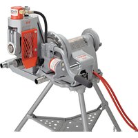
Roll Groover
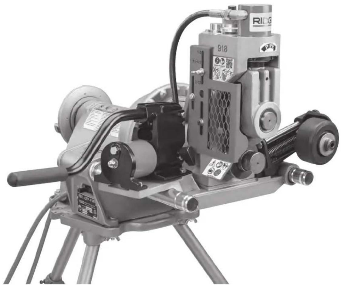
918 Roll Groover
natural_image
Industrial machine with tripod base and mechanical components, no visible text or symbols
WARNING!
Read this Operator's Manual carefully before using this tool. Failure to understand and follow the contents of this manual may result in electrical shock, fire and/or serious personal injury.
| 918 Roll Groover | |
| Record Serial Number below and retain product serial number which is located on nameplate. | |
| Serial No. | |
Safety Symbols
In this operator's manual and on the product, safety symbols and signal words are used to communicate important safety information. This section is provided to improve understanding of these signal words and symbols.

This is the safety alert symbol. It is used to alert you to potential personal injury hazards. Obey all safety messages that follow this symbol to avoid possible injury or death.

DANGER
DANGER indicates a hazardous situation which, if not avoided, will result in death or serious injury.

WARNING
WARNING indicates a hazardous situation which, if not avoided, could result in death or serious injury.

CAUTION
CAUTION indicates a hazardous situation which, if not avoided, could result in minor or moderate injury.
NOTICE
NOTICE indicates information that relates to the protection of property.

This symbol means read the operator's manual carefully before using the equipment. The operator's I contains important information on the safe and operation of the equipment.
manual contains important information on the safe and proper operation of the equipment.

This symbol means always wear safety glasses with side shields or goggles when handling or using this equipment to reduce the risk of eye injury.

This symbol indicates the risk of machine tipping, causing striking or crushing injuries.

This symbol indicates the risk of fingers and hands being crushed between the groove rolls.

This symbol indicates that the pipe to be grooved should be a minimum of 8" (200 mm) long to reduce the risk of injury.

This symbol means do not reach inside of pipe being grooved to reduce the risk of entanglement, cutting, crushing and other injuries.

This symbol means always use a foot switch when using the machine to reduce the risk of injury.

This is information symbol and indicates the product information available (including operators' manual) by scanning the adjacent QR code.
General Power Tool Safety Warnings\*
WARNING
Read all safety warnings, instructions, illustrations and specifications provided with this power tool. Failure to follow all instructions listed below may result in electric shock, fire and/or serious injury.
SAVE ALL WARNINGS AND INSTRUCTIONS FOR FUTURE REFERENCE!
The term "power tool" in the warnings refers to your mains-operated (corded) power tool or battery-operated (cordless) power tool.
Work Area Safety
- Keep work area clean and well lit. Cluttered or dark areas invite accidents.
- Do not operate power tools in explosive atmospheres, such as in the presence of flammable liquids, gases, or dust. Power tools create sparks which may ignite the dust or fumes.
- Keep children and by-standers away while operating a power. Distractions can cause you to lose control.
Electrical Safety
- Power tool plugs must match the outlet. Never mod ify the plug in any way. Do not use any adapter plugs with earthed (grounded) power tools. Unmodi fied plugs and matching outlets will reduce risk of electric shock.
- Avoid body contact with earthed or grounded surfaces such as pipes, radiators, ranges and refrigerators. There is an increased risk of electrical shock if your body is earthed or grounded.
- Do not expose power tools to rain or wet conditions. Water entering a power tool will increase the risk of electrical shock.
-
Do not abuse the cord. Never use the cord for carrying, pulling or unplugging the power tool. Keep cord away from heat, oil, sharp edges or moving parts. Damaged or entangled cords increase the risk of electric shock.
-
When operating a power tool outdoors, use an extension cord suitable for outdoor use. Use of a cord suitable for outdoor use reduces the risk of electric shock.
- If operating a power tool in a damp location is unavoidable, use a ground fault circuit interrupter (GFCI) protected supply. Use of a GFCI reduces the risk of electric shock.
Personal Safety
- Stay alert, watch what you are doing and use common sense when operating a power tool. Do not use a power tool while you are tired or under the influence of drugs, alcohol, or medication. A mo ment of inattention while operating power tools may result in serious personal injury.
- Use personal protective equipment. Always wear eye protection. Protective equipment such as dust mask, non-skid safety shoes, hard hat, or hearing protection used for appropriate conditions will reduce personal injuries.
- Prevent unintentional starting. Ensure the switch is in the OFF-position before connecting to power source and/or battery pack, picking up or carrying the tool. Carrying power tools with your finger on the switch or energizing power tools that have the switch ON invites accidents.
- Remove any adjusting key or wrench before turning the power tool ON. A wrench or a key left attached to a rotating part of the power tool may result in personal injury.
- Do not overreach. Keep proper footing and balance at all times. This enables better control of the power tool in unexpected situations.
- Dress properly. Do not wear loose clothing or jewelry. Keep your hair, and clothing away from moving parts. Loose clothes, jewelry, or long hair can be caught in moving parts.
- If devices are provided for the connection of dust extraction and collection facilities, ensure these are connected and properly used. Use of dust collection can reduce dust-related hazards.
- Do not let familiarity gained from frequent use of tools allow you to become complacent and ignore tool safety principles. A careless action can cause severe injury within a fraction of a second.
Power Tool Use and Care
- Do not force power tool. Use the correct power tool for your application. The correct power tool will do the
job better and safer at the rate for which it is designed.
- Do not use power tool if the switch does not turn it ON and OFF. Any power tool that cannot be controlled with the switch is dangerous and must be repaired.
- Disconnect the plug from the power source and/or the battery pack, if detachable, from the power tool before making any adjustments, changing accessories, or storing power tools. Such preventive safety measures reduce the risk of starting the power tool accidentally.
- Store idle power tools out of the reach of children and do not allow persons unfamiliar with the power tool or these instructions to operate the tool. Power tools are dangerous in the hands of untrained users.
- Maintain power tools and accessories. Check for misalignment or binding of moving parts, breakage of parts and any other condition that may affect the power tool's operation. If damaged, have the power tool repaired before use. Many accidents are caused by poorly maintained power tools.
- Keep cutting tools sharp and clean. Properly maintained cutting tools with sharp cutting edges are less likely to bind and are easier to control.
- Keep handles and grasping surfaces dry, clean and free from oil and grease. Slippery handles and grasping surfaces do not allow for safe handling and control of the tool in unexpected situations.
- Use the power tool, accessories and tool bits etc. in accordance with these instructions, taking into account the working conditions and the work to be performed. The use of the power tool for operations different from those intended could result in a hazardous situation.
Service
- Have your power tool serviced by a qualified repair person using only identical replacement parts. This will ensure that the safety of the power tool is maintained.
Specific Safety Information
WARNING
This section contains important safety information that is specific to this tool.
Read these precautions carefully before using the 918 Roll Groover to reduce the risk of electrical shock or other serious injury.
SAVE ALL WARNINGS AND INSTRUCTIONS FOR FUTURE REFERENCE!
Keep this manual with machine for use by the operator.
Roll Groover Safety
- Keep hands away from groove rolls. Do not wear loose fitting gloves. Fingers can be crushed between groove rolls, groove roll and pipe or between pipe and stabilizer wheel.
- Keep hands away from ends of pipe. Do not reach inside pipe. Do not touch groove while operating. Burrs and sharp edges can catch and cut. Fingers can be crushed between groove rolls or between groove roll and pipe.
- Keep guards in place. Do not operate the roll groover with the guard removed. Exposure to groove rolls may result in entanglement and serious injury.
- Properly adjust guard to reduce the risk of entanglement and serious injury.
- Only groove pipe 8" (200 mm) or longer. Grooving shorter than specified pipe can result in entanglement and crushing injuries.
- Do not wear loose clothing when operating machine. Keep sleeves and jackets buttoned. Do not reach across the machine or pipe. Clothing can be caught by the pipe or machine resulting in entanglement.
- Do not use this roll groover with a power drive or threading machine that does not have a foot switch. Never block a foot switch in the ON position so it does not control the machine. A foot switch provides better control by letting you shut off the machine motor by removing your foot. If entanglement should occur and power is maintained to the motor, you will be pulled into the machine. This machine has high torque and can cause clothing to bind around your am or other body parts with enough force to crush or break bones or cause striking or other injuries.
- Be sure that the roll groover, pipe, stands and machine are stable. Be sure the roll groover is properly set up and secured. This will help prevent tipping of the equipment and pipe. Properly support the pipe. This will help to prevent the tipping of the pipe and equipment.
- Properly prepare and handle pipe. Burrs and sharp edges can catch and cut.
- One person must control the work process, ma-
chine operation and foot switch. Only the operator should be in the work area when the machine is running. This helps reduce the risk of injury.
- Restrict access or barricade the area when workpiece extends beyond machine to provide a minimum of one meter (3 feet) clearance from the workpiece. Restricting access or barricading the work area around the workpiece will reduce the risk of entanglement.
- Only use power drives and threading machines that operate under 58 rpm. Higher speed machines increase the risk of injury.
- Always wear appropriate personal protective equipment while setting up and using the roll groover. Appropriate personal protective equipment always includes eye protection and may include equipment such as tight fitting leather gloves and steel toed footwear.
- Only use roll groover to groove pipe of recommended sizes and types according to these instructions. Other uses or modifying the roll groover for other applications may increase the risk of injury.
- Before operating roll groover, read and understand:
- This operator's manual
- The operators' manual for Power Drive or Threading Machine
- The fitting manufacturer's installation instructions
- The instructions for any other equipment or material used with this machine
Failure to follow all instructions and warnings may result in property damage and/or serious injury.
RIDGID Contact Information
If you have any question concerning this RIDGID® product:
- Contact your local RIDGID ^ distributor.
- Visit RIDGID.com to find your local RIDGID contact point.
- Contact Ridge Tool Technical Service Department at ProToolsTechService@Emerson.com, or in the U.S. and Cana da call 844-789-8665.
Description
The RIDGID® 918 Roll Groover is designed to form rolled grooves in steel, stainless steel, aluminum, PVC pipes and copper tubes. The grooves are formed by hydraulically advancing the groove roll into the pipe, which is supported by the drive roll.
The 918 Roll Groover typically includes two groove and drive roll sets for grooving pipe:
• 2"-6" schedule 10 and 40 steel pipe
- 8"-12" schedule 10 and 8" Schedule 40 steel pipe
Other materials can be grooved – see tables in appendix. Other groove and drive shaft sets are required for other sizes and copper tubing.
A two-stage hydraulic hand pump is used to advance the groove roll into the pipe to form grooves. A groove depth gauge is provided to aid in groove set up and an adjustment nut is included to control groove diameter.
An adjustable stabilizer is provided to aid in maintaining tracking and control of the pipe during grooving, especially pipe lengths approaching the 8" minimum pipe length.
The groover can be driven by a variety of RIDGID machines. Different mounting kits are required for each machine.
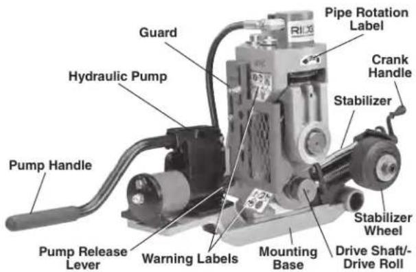
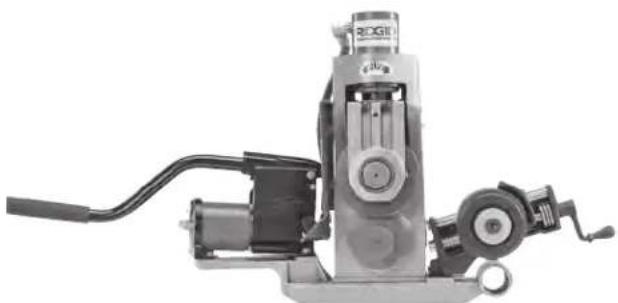
Figure 1A - 918 Roll Groover
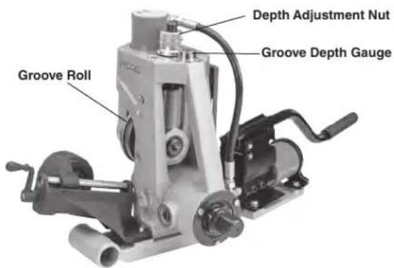
Figure 1B - 918 Roll Groover
Specifications
Materials, Pipe......Steel, Stainless Steel, Aluminum and PVC
Capacity
Standard Groove
Roll Sets 2"-6" schedule 10 and 40 steel pipe
Optional Groove
Roll sets....8"-12" schedule 10 and 8" Schedule 40* steel pipe
1 1/4" to 1 1/2" schedule 10 and 40 steel pipe
2" - 6" Copper Tube (Type K, L, M, & DWV)
Refer to the Table I, II and III for other materials and wall thicknesses
Groove Diameter
Adjustment......Groove Depth Gauge and Depth Adjustment Nut
Actuation....2 Stage Hydraulic Hand Pump
Stabilizer.... Manually adjusted, for 2 ^1/2 " to 12" Pipe
Mounting Bases
Available ...... RIDGID 300 Power Drive
RIDGID 1224 Threading Machine
RIDGID 535A/M Threading Machine
RIDGID 300 Compact/1233
Threading Machine
Weight (918, 300 PD Base,
Stabilizer)....82 lbs. (37 kg)
Dimensions (918, 300 PD Base,
Stabilizer) WxDxH ... 35" x 14" x 17.5"
(889 mm x 356 mm x 445 mm)
*Do not use to groove 8" schedule 40 steel pipe harder than 150 BHN. This may result in improperly formed/out of specification grooves.
NOTICE When properly used, the Model 918 Roll Groover is designed to make grooves in 1" - 12" pipe that are dimensionally within the specifications of AWWA C606-15. Improper use of this equipment can make out of specification grooves and damage the pipe and equipment.
Selection of appropriate materials and joining methods is the responsibility of the system designer and/or installer. Before any installation is attempted, careful evaluation of the specific service environment, including chemical environment and service temperature, should be completed. Selection of improper materials and methods could cause system failure.
Stainless steel and other corrosion resistant materials can be contaminated during installation, joining and forming. This contamination could cause corrosion and premature failure. Careful evaluation of materials and meth-
ods for the specific service conditions, including chemical and temperature, should be completed before any installation is attempted.
Standard Equipment
Refer to the RIDGID catalog for details on accessories supplied with specific machine catalog numbers.
Assembly
WARNING
To reduce the risk of serious injury during use, follow these procedures for proper assembly.
Assembling 918 to Bases for Various Machines
- Mount the 918 on appropriate machine base, aligning with 12 " holes. When installing on the 1224 base, install the spacer plate between the base and 918. Insert two 12 " bolts from underside of base and securely tighten with 34 " Wrench.
- Mount the hydraulic pump on the base and secure with four 14 " bolts, securely tighten with 716 " wrench. For the 1224 base, the pump bracket will need to be mounted to the base, and the pump attached to the pump bracket.
- Mount the stabilizer on the base. Insert two/8" screws through the base and securely tighten with 5/16" hex key.
- For the 1233/300 Compact, loosely attach the rail clamp to the underside of the base.
- See Figures 2 - 5 for details.
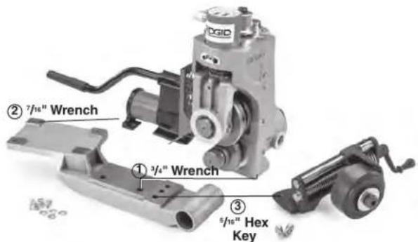
Figure 2A – Assembling 918 to 300 PD Base
natural_image
Mechanical device with attached motor and cable, no visible text or symbolsFigure 2B – Assembling 918 to 300 PD Base
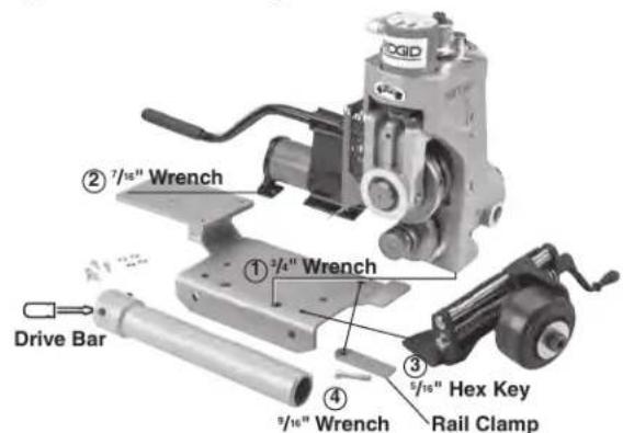
Figure 3 – Assembling 918 to 300 Compact/1233 Base
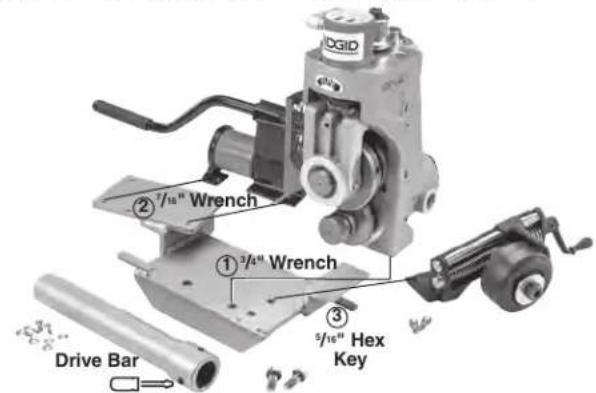
Figure 4 – Assembling 918 to 535 Base
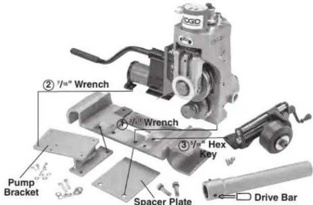
Figure 5 – Assembling 918 to 1224 Base
Pre-Operation Inspection
WARNING


Do not use this roll groover with a power drive/hreading machine that does not have a foot switch. Before each use, inspect your roll groover and correct any problems to reduce the risk of serious injury from crushing injuries and other causes and prevent roll groover damage.
- If installed on a machine, place the machine switch in the OFF position and unplug.
-
Clean any oil, grease or dirt from the roll groover, including the pump handle and stabilizer crank handle. This aids inspection and helps prevent the machine or control from slipping from your grip.
-
Inspect the roll groover for the following:
• Proper assembly, maintenance and completeness.
- Broken, worn, missing, misaligned or binding parts.
- Hydraulic leaks. Oil on the groover can indicate a hydraulic leak.
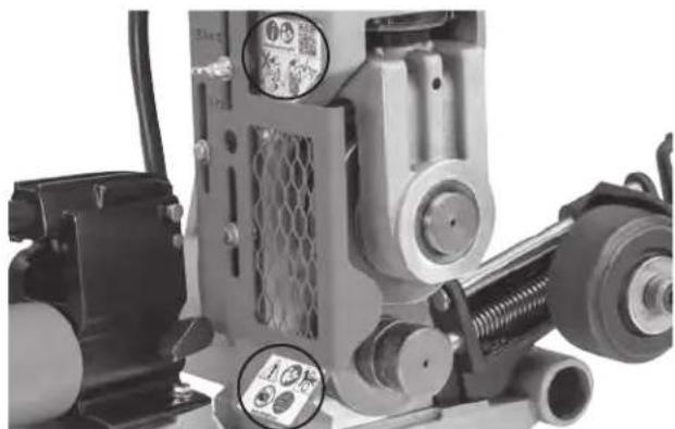
- Presence and condition of the guard (See Figure 1). Do not operate the roll groover without the guard. Guard should freely move between settings and securely stay in place.
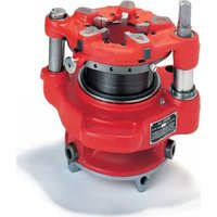
- Presence and readability of the warning labels (see Figure 6).
- Condition of the groove roll and drive roll. If the drive roll knurls are dirty, clean with a wire brush. Dirty or worn knurls can cause pipe slippage and tracking issues during grooving.
• Condition of the stabilizer wheel. Replace if needed.
- Any other condition which may prevent safe and normal operation.
- If any issues are found, do not use the roll groover until the issues have been repaired.
4. Inspect and maintain any other equipment being used per its instructions to make sure it is functioning properly. Confirm that the Power Drive or Threading Machine has a foot switch in good working condition.
natural_image
Close-up of industrial machinery components including rollers, springs, and a motor (no visible text or symbols)Figure 6 – Warning Labels
Machine and Work Area Set-up
WARNING


Set up the roll groover and the work area according to these procedures to reduce the risk of injury from machine tipping, crushing and other causes, and to help prevent machine damage.
Be aware of the equipment weight. Use appropriate methods when lifting or moving.
Secure roll groover to power drive or threading machine. Properly support pipe. This will reduce the risk of falling pipe, tipping and serious injury.
- Locate a work area that has the following:
- Adequate lighting.
- Clear, clean, level, stable and dry place for all equipment and operator. Clean up any oil that may be present.
-
Inspect the pipe to be grooved and determine the correct tool for the job, see Specifications. Grooving equipment for other applications can be found in the RIDGID catalog online at RIDGID.com. Do not use to groove anything other than straight stock. Do not groove pipe with protrusions or outlets such as Tees or elbows. This increases the risk of entanglement.
-
Confirm all equipment to be used has been properly inspected and assembled. Confirm that the correct grooving roll set is installed in the roll groover for the application.
U NOTICE ets (groove roll and drive roll)
on both carbon and stainless steel pipe can lead to
contamination of the stainless steel material. This contamination could cause corrosion and premature pipe failure. To prevent ferrous contamination of stainless steel pipe, use roll sets dedicated for stainless steel grooving. Alternately, a stainless steel wire brush can be used to thoroughly clean the roll set when switching between materials.
- Set up the Power Drive or Threading Machine per its instructions in the flat level area. Confirm that the REV/O-OFF/FOR switch is in the OFF position.
If using the 918 with a 535A (Auto Chuck) machine, it is recommended that the machine be configured for the chuck jaws to grip the pipe during REV rotation of the machine. This allows the stabilizer to be used when grooving. See the 535 Auto Chuck Manual, Left Hand Threading section for information on configuring the chuck jaws to grip the pipe during REV rotation of the machine.
-
Install 918 on Power Drive/Threading Machine – see section for setting up on specific equipment. Confirm that the equipment is secure and stable.
-
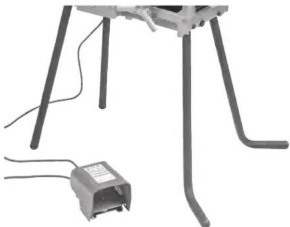
Position the foot switch for proper operation as shown in Figure 19.
-
After the 918 is properly installed, with dry hands, plug machine into appropriate outlet per its instructions.
Installing 918 On 300 Power Drive
-
Confirm 918 and base are properly assembled.
-
Remove carriage or other attachments from the support arms of the 300 Power Drive. Confirm that the power drive support arms are fully extended and fixed in position.
-
Fully open front chuck of power drive.
-
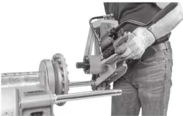
Slide the opening in the base (stabilizer side) over the rear support arm and lower the pump to the front support arm (Figure 7A).
-
Move the base toward the 300 Power Drive
-
Center drive shaft in the machine chuck. Align the drive shaft flats with the machine chuck jaws.
-
Securely tighten the front chuck on the flats of the drive shaft. See Figure 7B.
natural_image
Person operating a mechanical tool with a motor, no visible text or symbolsFigure 7A – Installing 918 on 300 Power Drive
natural_image
Close-up of mechanical components with no visible text or symbolsFigure 7B – Securing Drive Shaft In Chuck
Installing 918 On 300 Compact/1233 Threading Machines
If the 300 Compact or 1233 threading machines are mounted on straight pipe legs into the machine base, do not use with the 918 roll groover. The set up may not be stable enough for grooving forces. Pipe legs with feet that provide improved stability (Catalog # 56532) are available for this use. See Figure 8A for proper orientation of the legs. The 10 mm bolts will go through the holes in the leg to properly orient the foot of the leg.
The 918 Roll Groover cannot be used with machines mounted on the 250 Folding Stand. The stand handle interferes with the pipe being grooved. The 918 with the
appropriate base can be used with the 100A/150A/200A stands.
- Confirm that the 918 is properly assembled on the correct base for the machine it will be used with.
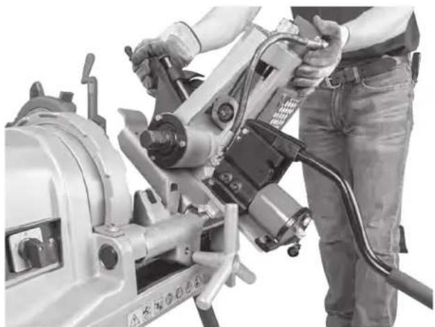
- Position machine carriage towards front chuck and swing carriage mounted tools up away from the operator. Position reamer inside the die head to secure and reduce risk of contact.
- Fully open front chuck of threading machine. Insert drive bar into machine chuck, but do not secure at this time.
- Place the open slot (pump side) of the base over the front carriage rail (Figure 8B) and lower the stabilizer to the rear carriage rail.
- Place the drive bar over the drive shaft flats. Align the drive shaft flats with set screws in the drive bar and securely tighten the set screws.
- With the 918 positioned at the end of the threading machine securely tighten the machine front chuck on the drive bar. See Figure 8C.
- Place the rail clamp under the rear carriage rail and secure. See Figure 8D.
natural_image
Close-up of a mechanical device with attached electrical connector (no visible text or symbols)Figure 8A - Catalog #56532 Legs with feet installation
natural_image
Person operating a mechanical tool with visible wiring and components (no text or symbols)Figure 8B – Installing 918 on 1233 Threading Machine
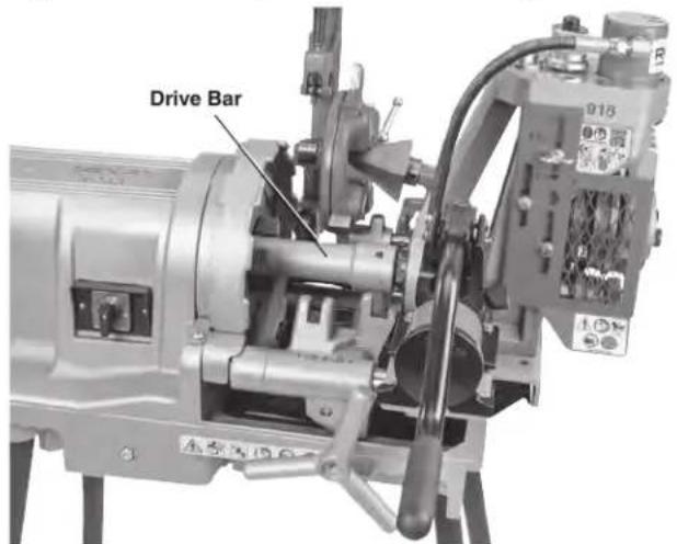
Figure 8C – Drive Bar Installation
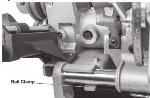
Figure 8D – Installing Rail Clamp
Installing On 535 and 1224 Threading Machines
Generally, the 918 can be installed on the 535 and 1224 machines with the drive bar installed, but it can also be
installed separately as done on the 300 Compact/1233 machines (see that section)
If using with a 535 Auto Chuck Threading Machine, set the machine up so that the chuck jaws grip the pipe during REV rotation of the machine, as detailed in the Left Hand Threading section of the 535 Threading Machine Operator's Manual.
- Confirm that the 918 is properly assembled on the correct base for the machine it will be used with. Securely attach the drive bar to the driveshaft.
- Position machine carriage towards front chuck and swing carriage mounted tools up away from the operator. Position reamer inside the die head to secure and reduce risk of contact.
- Fully open front chuck of threading machine.
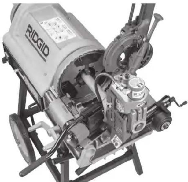
- With the end of the drive bar in the machine chuck, place the open slot of the base (stabilizer side) over the rear carriage rail and lower the pump to the front carriage rail. See Figure 9.

natural_image
Close-up of a robotic arm tool in operation, showing mechanical components and a hand adjusting a component (no visible text or symbols)Figure 9 – 918 Roll Groover on 535 Threading Machine Mounting Base
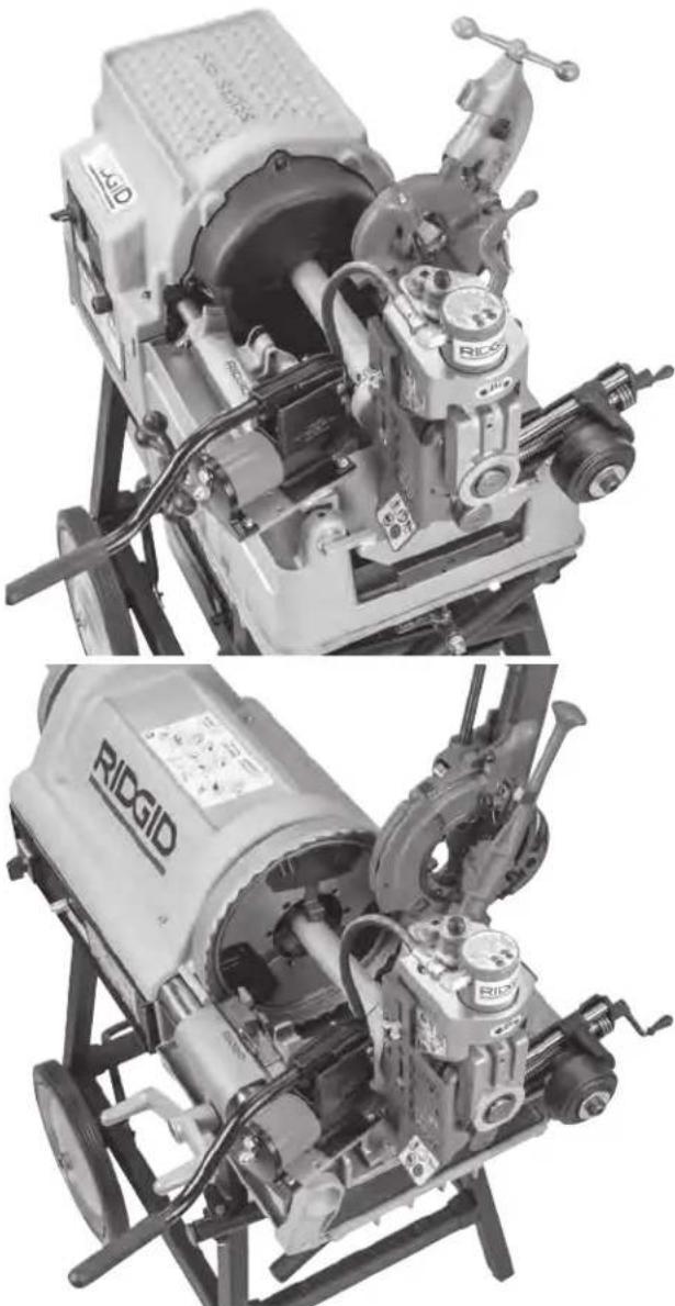
- With the 918 positioned at the end of the threading machine securely tighten the machine front chuck on the drive bar. See Figure 10.
natural_image
Two views of a RRDGID industrial machine with visible internal components and external blades (no text or symbols)Figure 10 - 918 installed on 535A and 1224
Operation

Keep hands away from grooving rolls. Do not wear loose fitting gloves. Fingers can be crushed between groove rolls, groove roll and pipe or between pipe and stabilizer wheel.
Keep hands away from ends of pipe. Do not reach inside pipe. Do not touch groove while operating. Burrs and sharp edges can catch and cut. Fingers
can be crushed between groove rolls or between groove rolls and pipe.
Keep guards in place. Do not operate the roll groover with the guard removed. Exposure to groove rolls may result in entanglement and serious injury.
Only groove pipe 8" (200 mm) or longer. Grooving shorter than specified pipe can result in entanglement and crushing injuries.
Do not use this roll groover with a power drive or threading machine that does not have a foot switch. Never block a foot switch in the ON position so it does not control the machine. A foot switch provides better control by letting you shut off the machine motor by removing your foot. If entanglement should occur and power is maintained to the motor, you will be pulled into the machine. This machine has high torque and can cause clothing to bind around your am or other body parts with enough force to crush or break bones or cause striking or other injuries.
Be sure that the roll groover, pipe, stands and machine are stable. Be sure the roll groover is properly set up and secured. This will help prevent tipping of the equipment and pipe. Properly support the pipe. This will help to prevent the tipping of the pipe and equipment.
Always wear eye protection. Wear steel toe footwear to help protect from tipping tools and falling pipe.
Set up and operate the roll groover according to these procedures to reduce the risk of injury from machine tipping, entanglement, crushing, striking and other causes, and to help prevent equipment damage.
- Confirm that the machine and work area is properly set up and that the work area is free of bystanders and other distractions. The operator should be the only person in the area when the machine is operated.
- Position the foot switch for proper operation as shown in Figure 19.
- Check the roll groover for proper operation. While keeping your hands clear of moving parts:
- Move the power drive/threading machine REV/O-OFF/FOR switch to the REV position. Press and release the foot switch. Drive roll should rotate clockwise (see Figure 15) matching the pipe rotation decal on the groover. If the groover does not rotate in the correct direction, or the foot switch does not control the machine operation, do not use the machine until it has been repaired.
- Depress and hold the foot switch. Inspect the moving parts for misalignment, binding, odd noises or any other unusual conditions. Confirm that the machine rotates less than 58 rpm. Higher speeds can increase the risk of injury. Remove foot from the
foot switch. If any unusual conditions are found, do not use the machine until it has been repaired.
- Move the REV/O-OFF/FOR switch to the OFF position, and with dry hands unplug the machine.
Pipe Preparation
NOTICE These are generalized instructions. Always follow grooved coupling manufacturer's specific recommendations for pipe end preparation. Failure to follow these recommendations may lead to an improper connection and cause leaks.
- Be aware of pipe specifications acceptable for grooving. Out of specification pipe can cause leaks and other issues. Pipe out-of-roundness must not exceed total O.D. tolerance listed in the Standard Roll Groove Specifications, Table II.
-
Cut pipe to proper length. Be aware of the minimum pipe lengths for grooving.
-
5" and smaller diameter pipe should not be shorter than 8" (200 mm) long.
- 6" to 12" diameter pipe should not be shorter than 10" (250 mm) long.
Grooving shorter pipe increases the risk of injury from crushed fingers and entanglement.
- Make sure pipe end is cut square and free of burrs. Burrs can catch or cut gloves or fingers during grooving. Cut off method and large burrs can affect the quality of the groove made and tracking of the groover. Do not attempt to groove pipe that has been cut with a torch.
- Remove all internal/external weld beads, flash, seams, scale, dirt, rust and other contaminants at least 2" back from the end of the pipe. Do not cut flats into gasket seat area, this could cause leaks. Contaminants can clog the drive knurls and prevent proper driving and tracking of the pipe while grooving.
Advance/Retract The Groove Roll
The movement of the groove roll is controlled by the hydraulic pump.
- To advance the groove roll, move the pump lever to the advance position, then move the pump handle up and down.
- To retract the groove roll, move the pump lever to the retract position. See Figure 11.
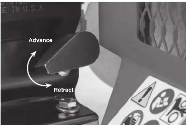
Figure 11 – Pump Release Lever Position
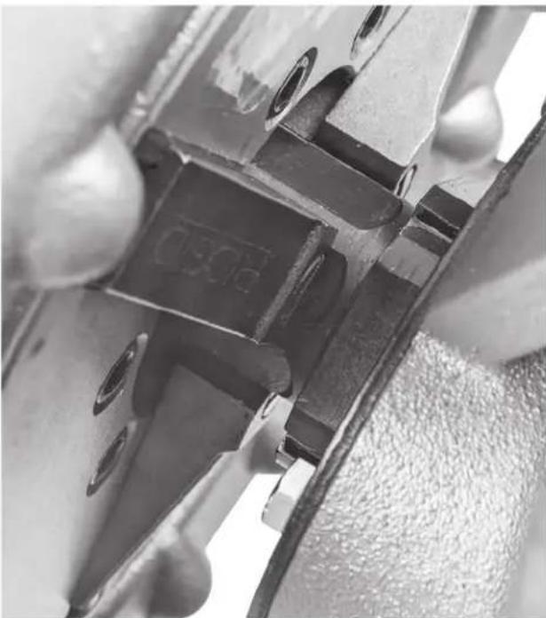
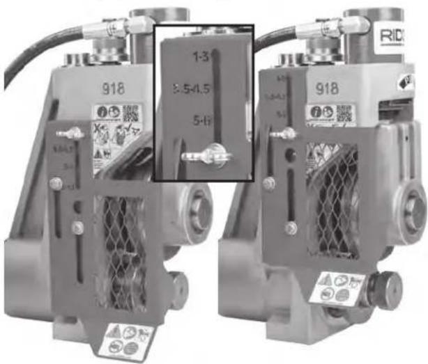
Setting Adjustable Guard
- Confirm the size of the pipe that is going to be grooved.
- Locate the engraved pipe sizes on the guard face. Find the range of sizes that the pipe falls within.
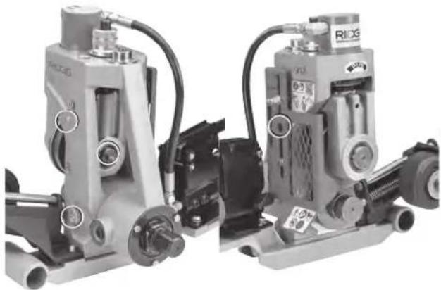
- Loosen the wing-screw. Adjust the position of the guard so that the correct range of sizes aligns with the position of the wing-screw. Properly adjust guard to reduce the risk of entanglement and serious injury (Figure 12).
- Securely tighten the wing screw.
natural_image
Two identical industrial mechanical components labeled 918, showing internal components and wiring (no readable text or symbols beyond labels)Figure 12 – Setting Adjustable Guard
Loading Pipe in Roll Groover
- Confirm that the machine switch is in the OFF position.
-
Fully retract the groove roll.
-
Appropriate pipe stands must be available to support the pipe. Adjust the height of the pipe stands so that the pipe will be level and the top inner diameter of the pipe will sit on top of the drive roll (see Figure 13).
Place the pipe stands directly in front of the roll groover. Pipe stand placement depends on the pipe length.
For shorter pipe (see Chart A) the pipe is supported by the drive shaft and at least one stand. In this case, the stand should be placed slightly more than half the length of the pipe from the roll groover.
| Nom. Size | Min. Length | Max. Length | Nom. Size | Min. Length | Max. Length |
| 1 | 8 | 36 | 4 | 8 | 36 |
| 1^1/4 | 8 | 36 | 4^1/2 | 8 | 32 |
| 1^1/2 | 8 | 36 | 5 | 8 | 32 |
| 2 | 8 | 36 | 6 O.D. | 10 | 30 |
| 2^1/2 | 8 | 36 | 6 | 10 | 28 |
| 3 | 8 | 36 | 8 | 10 | 24 |
| 3^1/2 | 8 | 36 | 10 | 10 | 24 |
| 4 | 8 | 36 | 12 | 10 | 24 |
Chart A - Minimum/maximum pipe length to be grooved with one stand (in inches)
For longer pipes at least two stands should be used, with the two stands placed approximately 1/4 of the pipe length from the ends of pipe. Failure to properly support the pipe may allow the pipe or the pipe and machine to tip and fall. Always use a pipe stand – it helps to align the pipe and maintain proper tracking.
natural_image
Mechanical assembly diagram showing a mechanical component with gears and shafts (no visible text or symbols)Figure 13 – Placing Pipe over Drive shaft, Flush to drive shaft flange (Stabilizer removed for clarity)
- Place the pipe on the stand(s) with the end of the pipe flush to the drive shaft flange and the inside of the pipe contacting the top of the drive shaft (Figure 13). Make sure the pipe is stable and secure.
natural_image
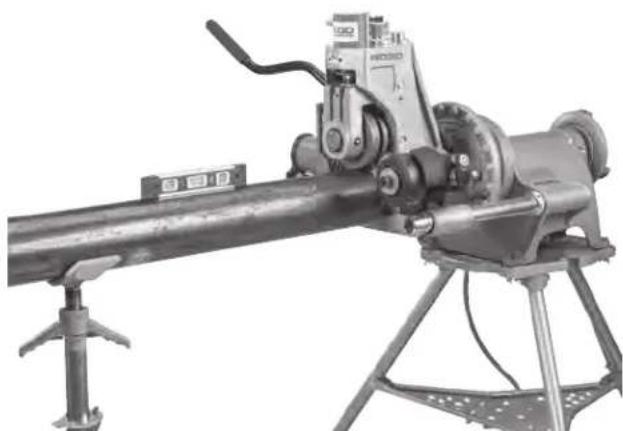
Mechanical device with articulated arm and tripod base, no visible text or symbolsFigure 14 – Leveling Pipe
- Advance the groove roll until it touches and lightly grips the pipe (Do not drive the groove roll into the pipe).
-
Confirm the pipe positioning. If the pipe is not properly positioned, the groove may not track properly.
-
The pipe end should be flush against the driveshaft flange.
- The centerline of the pipe and the centerline of the drive shaft should be parallel. This can be checked with a level on top of the hydraulic cylinder and on the pipe. See Figure 14.
-
The roll groover/machine should be sitting firmly on the ground. If the machine is lifting off the ground at all, the pipe stand(s) are set improperly and should be adjusted.
-
Preferred Operation - Switch in REV Setting:
Slightly offset the pipe and pipe stands approximately 1/2 degree (about 1" over at 10 feet from the roll groover) towards the operator. Proper alignment of the pipe and roll groover helps to ensure proper tracking of the pipe while grooving (see Figure 15). This is proper offset for grooving with the machine in the REV switch setting, and works with the stabilizer.
Alternate Operation – Switch in FOR Setting: If using the machine in the FOR switch setting (such as with a 535 Auto Chuck Machine not converted to grip in both directions), then offset the pipe and pipe stands approximately 1/2 degree (about 1" over at 10 feet from the roll groover) away from the operator (see Figure 16). The pipe stabilizer cannot be used with the FOR switch setting – it may cause pipe to spiral out of the roll set.
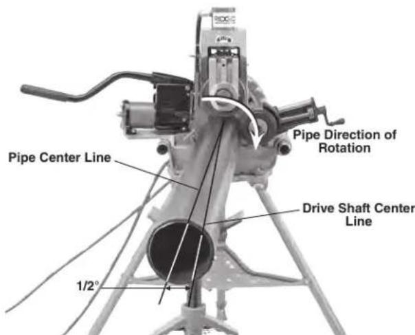
Figure 15 – Offsetting the Pipe 1/2° Toward Operator, (Exaggerated)
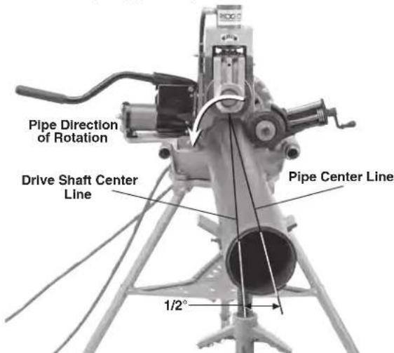
Figure 16 – Offsetting the Pipe 1/2° Away from Operator, (Exaggerated)
- Restrict access or set up guards or barriers to create a minimum 3' (1m) clearance around the equipment and pipe. This helps prevent non-operators from contacting the equipment or pipe and reduces the risk of tipping or entanglement.
- With dry hands, plug the power drive/threading machine into a properly grounded outlet.
Setting/Adjusting Groove Diameter
NOTICE Due to differing pipe characteristics, a test groove should always be performed before the first groove of the day or when changing pipe size, schedule, material, or lot to reduce the risk of out of tolerance grooves. Groove diameter must be measured to confirm proper size.
- Confirm that equipment is properly set up and pipe is
properly prepared and loaded. Improper set up and preparation can affect accuracy of groove diameter settings.
-
Groove roll should be contacting the pipe. If needed, advance the groove roll to just contact the pipe. It should not be gripping or making an indentation in the pipe.
-
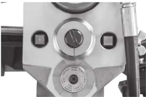
Adjust the groove depth gauge so that the correct step of the gauge is under the head of the adjusting screw (Figure 17A). The groove depth gauge is designed for use with pipe. See "Setting The Groove Diameter For Copper Tubing" for use with copper tube.
-
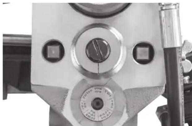
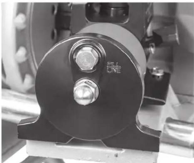
Turn the adjusting nut clockwise until the head touches the step of the depth gauge. Turn the groove depth gauge to the grooving position (Figure 17B). If the gauge is not in the grooving position it will prevent grooving and may be damaged.
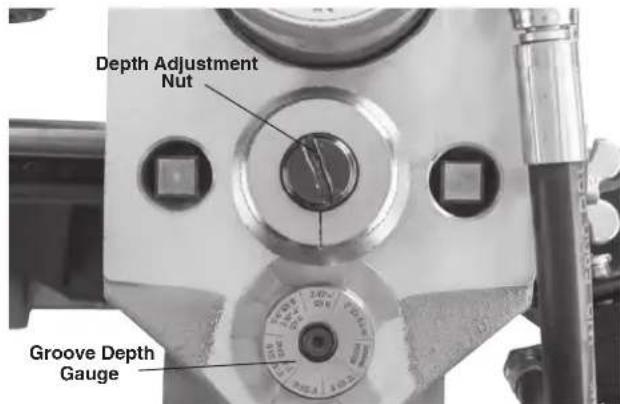
Figure 17A – Place Correct Step of Gauge Under Adjusting Head
natural_image
Close-up of a mechanical clamp or measuring device with circular components and adjustment knobs (no visible text or symbols)Figure 17B - Gauge in Grooving Position
-
Prepare a test groove (follow the steps for "Grooving Operation").
-
Measure the groove diameter. The best method for measuring the groove diameter is the use of a diameter tape (see Optional Equipment Section). Tightly wrap the diameter tape around the grooved section of the pipe. Make sure that the tape sits flat in the bottom of the groove, and read the groove diameter.
-
Compare the measured groove diameter to the required groove diameter as shown in Table II or III or as specified by the groove fitting manufacturer. If the measured groove is outside of the required groove diameter the adjustment nut can be adjusted to form a correct groove.
- To decrease groove diameter (deeper groove), turn the depth adjustment nut counterclockwise.
- To increase groove diameter (shallower groove), Turn the depth adjustment nut clockwise.
- Each 1/4 turn of the depth adjustment nut changes the groove diameter by approximately 0.025" (0.6 mm). Moving the nut one mark on the circumference changes the groove diameter by approximately 0.002" (0.05 mm).
- Repeat steps 6-8 until the groove diameter is within specifications. If the groove is too large, the groover can be adjusted and the groove made smaller. If the groove is too small, another groove will need to be made. Proper groove diameter is important to ensure connection performance. Out of specification grooves could cause joint failure.
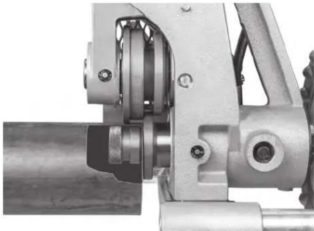
Stabilizer Operation
The stabilizer is used to apply slight force to 2/2" to 12" pipe to improve tracking. It is especially useful for short pieces of pipe, but can be used on all lengths of pipe. The stabilizer also reduces the swaying of longer, larger diameter pipe.
The stabilizer can only be used with the machine REV/O-OFF/FOR switch in the REV position (pipe rotation marked on groover, Figure 18). If used with the machine REV/O-OFF/FOR switch in the FOR position, the pipe will spiral/track out of the groove rolls.
-
Properly set up equipment and load pipe.
-
Set groove diameter.
-
Rotate the stabilizer crank handle to bring the roller in contact with the pipe. Rotate the crank handle an additional one (1) turn to preload the roller against the pipe (Figure 18). Do not reach across the pipe to adjust the stabilizer.
-
Groove pipe. During use, keep hands away from the groove rolls, stabilizer wheel and end of pipe. Do not groove pipe shorter than specifications and do not
reach inside pipe or touch the groove. This reduces the risk of crushing injuries.
If during grooving the pipe does not track properly, step off foot switch and stop grooving. Set up a new groove and rotate the crank handle an additional one half (1/2) turn to increase preload. Do not use excessive preload. This can damage the roller.
Once the stabilizer is set for a given size and type of material, it generally does not need to be readjusted or backed off when pipe is loaded and unloaded.
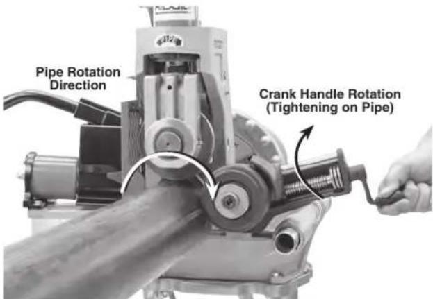
Figure 18 – Stabilizer Positioning
Grooving Operation
-
Confirm that equipment is properly set up and pipe is properly prepared and loaded. Properly adjust guard. Do not groove pipe shorter than 8".
-
Set groove diameter.
-
If needed, set the stabilizer position.
-
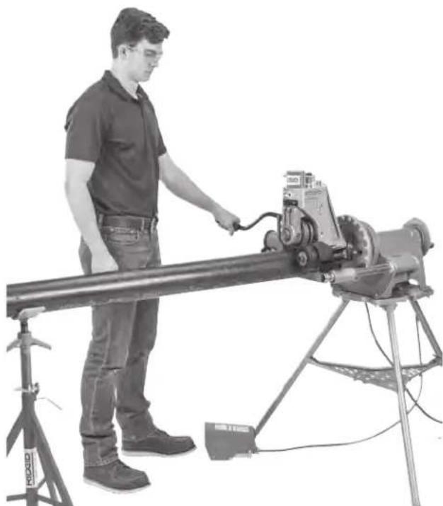
Assume a proper operating position to help maintain control of the machine and pipe (see Figure 19).
- Stand facing the roll groover on the REV/O-OFF/FOR switch side of the machine with convenient access to the switch, pump handle and pipe. Your left hand will be on the pump handle, and your right hand is clear of the pipe unless applying slight force to the pipe to maintain tracking (see Tracking Tips section).
- Be sure that you can control the foot switch. Do not step on foot switch yet. In case of emergency you must be able to release the foot switch.
- Be sure that you have good footing and balance and do not have to overreach.
natural_image
Man operating a large industrial machine on a tripod stand (no visible text or symbols)Figure 19 – Proper Operating Position
-
Move the REV/O-OFF/FOR to the REV position.
-
Apply approximately a quarter stroke of the pump handle to force the groove roll into the pipe.
-
Depress the foot switch. The pipe will start to turn. Allow one full pipe rotation between quarter strokes of the pump handle. Do not advance the groove roll too aggressively – this can cause the pipe to spiral out of the roll set and poor groove form. Keep your hands clear of the groove set, pipe end and stabilizer wheel. Do not reach inside the pipe or touch groove.
Monitor the pipe as it is grooved. The end of the pipe should stay in contact with the drive shaft flange, and the pipe should stay in position. If the pipe starts to move out of position, step off of the foot switch and stop grooving. Keep your body clear in case the pipe comes out of the grip of the roll set. If the pipe starts to come out of position stop grooving and check set up. If the pipe end is damaged, a new groove will need to be prepared.
Continue applying a quarter stroke of the pump handle every pipe rotation.
When using the 1" roll set, it is especially important to not apply excessive force (improper groove diameter setting, undersized grooves, more than a quarter stroke of pump handle per rotation). This can damage the 1" drive roll.
- When the depth adjustment nut contacts the top of the groover, allow the pipe to rotate at least two more full rotations to ensure uniform groove depth.
- Remove foot from the foot switch.
- Move the REV/O-OFF/FOR switch to the OFF position.
- Retract the groove roll and remove the pipe from the roll groover.
- Inspect and measure the groove.
Setting The Groove Diameter For Copper Tubing
When using the 918 Roll Groover for copper tube, the groove depth gauge on the groover cannot be used. It will give incorrect groove diameter.
- Advance the groove roll just to touch and lightly grip the tube.
- Make sure the groove depth gauge is in the grooving position. (Figure 17B)
- Turn the adjustment nut until it is flush with the top plate of the groover.
- Find the diameter and type of tube to be grooved on Table B and back the adjusting screw off the top plate the corresponding number of turns. For example, for 4" Type L copper, back the adjustment screw 1 turn.
| Depth Adjustment for Roll Grooving Copper Tubing (Adjusting Screw Turns) | ||||
| Diameter | K | L | M | DWV |
| 2-2.5" | 7/8 | 7/8 | 7/8 | 7/8 |
| 3" | 7/8 | 7/8 | 7/8 | 7/8 |
| 4" | 1 | 1 | 1 | 1 |
| 5" | 1^1/_4 | 1 | 1 | 1 |
| 6" | 1^3/_8 | 1^1/_4 | 1^1/_4 | 1^1/_4 |
Chart B – Depth Adjustment for Roll Grooving Copper Tubing
- Go to step 5 of "Setting/Adjusting Groove Diameter".
Tracking Tips
A typical issue while roll grooving is the pipe "spiraling" or "walking off" the drive shaft or not "tracking" properly.
For good tracking, it is important that all instructions be followed. If, even after following all instructions, the pipe will not properly track, there are other options to improve tracking.
- Slightly increase the offset of the pipe (increase from 1/2 degree to 1 degree). See Figure 15.
- Tighten the stabilizer crank handle an additional 1/2 turn.
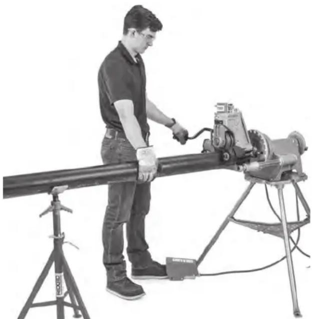
- The operator may need to apply slight force on the pipe while grooving to maintain tracking. This is usually only needed on shorter pieces of pipe when the stabilizer is not used. To do this, the operator should wear a leather glove in good condition and cup their hand around the pipe as shown in Figure 20 to pull the pipe slightly towards them. This may require that the power drive/threading machine stand be fixed to the floor to prevent movement during grooving. To reduce the risk of crushing and cutting injuries, keep hand away from the groove roll and the ends of the pipe, do not groove pipe shorter than recommended and do not reach inside pipe or touch groove.
natural_image
Man operating a large cylindrical mechanical device with a tripod stand nearby (no visible text or symbols)Figure 20 – Applying Pressure on Pipe with Power Drive in REV direction
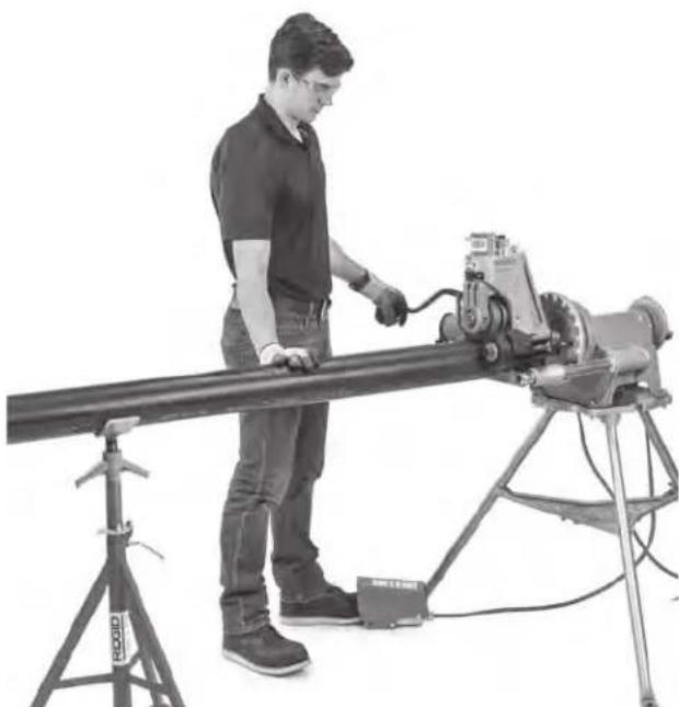
If the machine is run in the FOR direction, the stabilizer cannot be used. Move the stabilizer wheel away from the pipe. If the stabilizer is used in FOR, the pipe will spiral out of the groove rolls. If needed, the operator should wear a leather glove in good condition and use their right hand to push pipe slightly away from them as shown in Figure 21.
natural_image
Man operating a long industrial machine on a tripod stand, no visible text or symbolsFigure 21 – Applying Pressure on Pipe with Power Drive in FOR direction
Inspect/Measure the Groove
- Inspect the groove.
• Make sure that all features are present and fully formed. See Table II and Figure 31.
• Measure the groove diameter and make sure it is within specification.
- Check any other items required by the fitting manufacturer.
- Test the system in accordance with local codes and normal practice.
If any problems are found, the groove cannot be used. Proper groove diameter is important to ensure connection performance. Out of specification grooves could cause joint failure.
- Measure the groove diameter with diameter tape (see Optional Equipment Section). Snugly wrap the diameter tape around the pipe in the groove. Make sure that the tape sits flat in the bottom of the groove, and read the groove diameter (see Figure 22). Compare the measured groove diameter to the required groove diameter as shown in Table II or III or as specified by the groove fitting manufacturer.
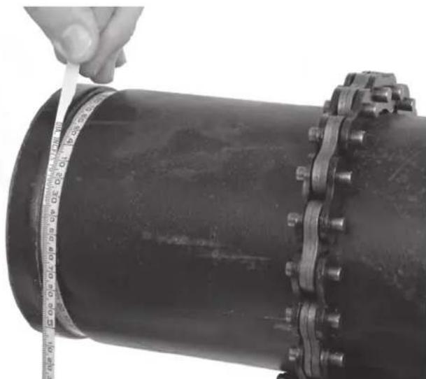
natural_image
Close-up of a hand measuring a large black pipe with a tape measure, showing bolt holes and flanges (no text or symbols visible)Figure 22 – Checking Groove Diameter with a Diameter Tape
Preparing Machine for Transport
Before transporting, remove the 918 from the power drive/threading machine. Be aware of the equipment weight. Use appropriate methods when lifting or moving.
Storage
⚠ WARNING The 918 Roll Groover must be kept indoors or well covered in rainy weather. Store the machine in a locked area that is out of reach of children and people unfamiliar with roll groovers. This machine can cause serious injury in the hands of untrained users.
Maintenance Instructions
WARNING
Make sure machine is unplugged from power source before performing maintenance or making any adjustments.
Maintain the 918 Roll Groover according to these procedures to reduce the risk of injury.
Cleaning
Use a soft damp cloth to clean the roll groover.
Clean the drive roll knurls with a wire brush before use and as necessary during operation. When grooving stainless steel pipe, thoroughly clean the entire roll set with a stainless steel wire brush.
Lubrication
On a monthly basis (or more often if needed), lubricate the groover with a lithium based general purpose grease. Always lubricate the roll groover after roll set changes.
- Lubricate the groover at grease fittings (See Figure 23). Add grease until a small amount pushes out.
natural_image
Two industrial mechanical devices with visible components and mounting brackets (no text or symbols)Figure 23 – Grease Fittings
- Apply a light lubricating oil to pivot points and areas of relative motion, such as the depth adjustment nut and the stabilizer feedscrew. Wipe any excess lubricant from exposed surfaces.
Hydraulic Fluid Level
Remove the reservoir filler cap (Figure 24). The oil level should come to the fill line when the pump is resting on its base and the ram is fully retracted. Use only ISO 15 hydraulic oil.
natural_image
Close-up of a mechanical assembly with a black circular component and two bolts (no visible text or symbols)Figure 24 – Reservoir Filler Cap
Once a year, or more often with heavy use or use in dusty conditions, the hydraulic oil should be changed. To drain oil, remove the reservoir filler cap and drain the oil in a container. Properly dispose of the used hydraulic oil per the Safety Data Sheet (SDS) and local requirements.
Hydraulic system may need air bled after changing fluid. To bleed hydraulic system, position ram lower than pump by tipping the machine on its side. Extend and return the cylinder piston several times to permit air to return to the pump reservoir.
Changing Roll Sets
NOTICE When changing roll set, always make sure drive roll and groove roll markings match. Mismatched parts can make improper grooves and cause leaks. Always change rolls as sets – do not mix rolls from different sets.
If installed, remove the roll groover from power drive or threading machine and place on a stable workbench.
Properly support the rolls and shafts while replacing.
Changing Groove Roll
- Fully retract the groove roll.
- Fully retract the stabilizer wheel.
- Loosen groove roll set screw (Figure 25). Grasp groove roll and remove upper shaft and groove roll from groover (Figure 26).
natural_image
Close-up of a mechanical tool with a hand adjusting a cable, no visible text or symbolsFigure 25 – Loosening Grooving Roll Set Screw
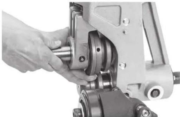
natural_image
Close-up of a hand operating a mechanical assembly with rotating components (no visible text or symbols)Figure 26 – Removing Retaining Shaft and Groove Roll
Changing Drive Shaft/Drive Roll
The 918 has two styles of drive shaft. A one piece drive shaft (used on the 2"-6" and 8"-12" sizes) and the two piece unit consisting of a drive shaft and interchangeable drive roll (used for the 1", 1^1/4 " to 1^1/2 " and 2"-6" Copper sizes). See Figure 27.
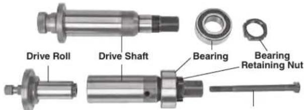
Figure 27 – One Piece Drive Shaft (Top), Two Piece Drive Shaft (Bottom)
- Remove the groove roll.
- Manually rotate the drive shaft while applying pressure to the spindle lock pin until the lock pin engages the spindle lock hole in the driveshaft.
Changing Drive Shaft
- With the spindle lock engaged, use the box wrench to remove the drive shaft bearing retaining nut (Figure 28).
- Release pressure on the spindle lock pin, allowing to retract.
- Remove the drive shaft from the front of the groover.
- Reverse steps to install. Make sure parts are clean to keep dirt out of bearings. Lubricate bearings before use.
natural_image
Close-up of hands operating a mechanical device with no visible text or symbolsFigure 28 – Engaging Spindle Lock and Removing Drive Shaft Retaining Nut
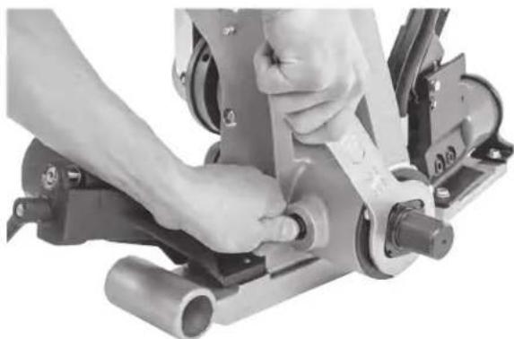
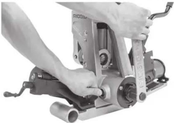
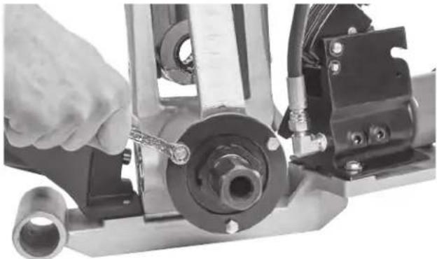
Changing Drive Roll (Two-Piece Drive Shafts)
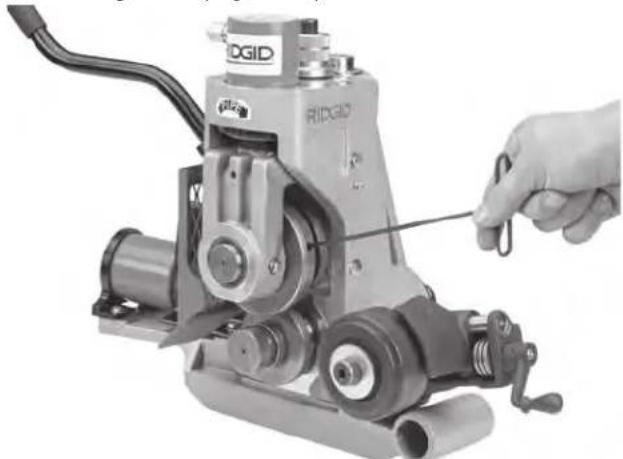
-
With the spindle lock engaged, use the 15/16" hex in the box wrench to loosen the draw bolt.
-
Tap draw bolt head with a soft face mallet to release drive roll from drive shaft.
- Unthread draw bolt from drive roll, remove drive roll from front of groover.
- Reverse steps to install. Make sure drive roll is fully seated in the drive shaft and draw bolt is secure.
natural_image
Close-up of hands operating a mechanical press or clamp device with no visible text or symbolsFigure 29 – Engaging Spindle Lock and Loosen Draw Bolt
natural_image
Close-up of a hand adjusting a mechanical component with a tool, no visible text or symbolsFigure 30 – Removing Retaining Plate Hex Screws
Changing One Piece Drive Shaft to Two Piece Drive Shaft
- Remove the one piece driveshaft.
- Remove the rear bearing retaining plate screws and the plate, see Figure 30.
- Remove the rear bearing out of the back of the 918 housing.
- Install the two piece drive shaft assembly into the back of the 918 housing. Make sure parts are clean to keep dirt out of bearings.
- Reinstall the rear bearing retaining plate and screws.
- Install the required drive roll. Lubricate bearings before use.
Troubleshooting
| PROBLEM PO | SSIBLE REASONS SOLUTION | |
| Groove too narrow or too wide. | Incorrect groove roll and drive shaft. Install correct groove roll and drive shaft. | |
| Groove roll and/or drive shaft worn. | Replace groove roll and/or drive shaft. | |
| Mismatched groove roll and drive shaft. | Install matching roll set. | |
| Rolled groove not perpendicular to pipe axis. | Pipe length not straight. Use straight pipe. | |
| Pipe end not square. Cut pipe end square. | ||
| Pipe does not track while grooving. Groover will not track on pipe while grooving. | Pipe and drive shaft not parallel. | Adjust stand to make pipe parallel. |
| Pipe axis not offset 1/2 degree from drive roll axis. | Offset pipe 1/2 degree. | |
| 1/2 degree offset not sufficient. Offset pipe slightly more. | ||
| Drive shaft/roll knurl plugged or worn flat. Clean or replace drive shaft/roll. | ||
| Inside of pipe has too much scale. | Clean inside of pipe. | |
| Excessive weld seam. Grind weld seam flush 2" from end of pipe. | ||
| Not using/properly adjusting stabilizer. | Adjust stabilizer. Apply pressure to pipe (see Figure 20/21). | |
| Pipe end not square/deburred. | Properly prep end of pipe | |
| Pipe flared at grooved end. | Pipe and drive shaft not parallel. | Adjust stand to make pipe parallel. |
| Operator is advancing groove roll too fast. | Slow down pumping action. Refer to Operating instructions. | |
| Pipe is too hard. | Replace pipe. | |
| Stabilizer too tight. | Adjust stabilizer. | |
| Pipe drifts back and forth on driving shaft axis while grooving. | Pipe length not straight | Use straight pipe. |
| Pipe end not square. | Cut pipe end square. | |
| Pipe rocks from side to side. | Pipe stand too close to end of pipe. | Move pipe stand in to match set-up Instructions. |
| Pipe end flattened or damaged | Cut off damaged pipe end. | |
| Hard spots in pipe material or weld seams harder than pipe. | Use different pipe | |
| Groove roll feed rate too slow. | Feed groove roll into pipe faster. | |
| Pipe supports stand not in correct location. | Position pipe stand rollers correctly. | |
| Power drive/threading machine speed exceeds 57 rpm. | Reduce speed to 57 rpm. | |
| Groover will not roll groove in pipe. | Maximum pipe wall thickness exceeded. | Check Table I. |
| Pipe material too hard. Replace pipe | ||
| Adjustment nut not set. | Set depth. | |
| Wrong roll set. | Install correct roll set. | |
| Groover will not roll groove to required diameter | Maximum pipe diameter tolerance exceeded. | Use correct diameter pipe. |
| Depth adjustment nut not set correctly. | Adjust depth setting. | |
| Pipe too hard. | Use different pipe. | |
| Pipe slips on drive roll. | Groove roll feed rate too slow. | Feed groove roll into pipe faster. |
| Drive shaft knurls plugged with metal or worn flat. | Clean or replace drive roll. | |
| Pipe raises or tends to tip Groover over backwards. | Pipe support stand not properly set up. | Properly set up stands. |
| PROBLEM POSSIBLE REASONS SOLUTION | ||
| Pump not delivering oil, cylinder does not advance. | Pump release valve open. Close release valve. | |
| Low oil in reservoir. Check oil level per instructions. | ||
| Dirt in pump body. Have serviced by qualified technician. | ||
| Seats worn or not seating Have serviced by qualified technician. | ||
| Too much oil in reservoir. Check oil level per instructions. | ||
| Pump handle operates with “spongy” action | Air trapped in system. Bleed air from hydraulic system per instructions. | |
| Too much oil in reservoir. Check oil level per instructions. | ||
| Cylinder extends only partially. | Pump reservoir is low on oil. Fill and bleed system. | |
| Depth adjustment set incorrectly. | Follow depth adjustment instructions. | |
Service And Repair
WARNING
Improper service or repair can make machine unsafe to operate.
The Maintenance Instructions will take care of most of the service needs of this machine. Any problems not ad dressed by this section should only be handled by an authorized RIDGID service technician.
Tool should be taken to a RIDGID Authorized Independent Service Center or returned to the factory. Only use RIDGID service Parts.
For information on your nearest RIDGID Authorized Independent Service Center or any service or repair questions, see Contact Information section in this manual.
Optional Equipment
WARNING
To reduce the risk of serious injury, only use accessories specifically designed and recommended for use with the RIDGID 918 Roll Groover, such as those listed.
| Catalog No. | Description |
| 48405 | Roll Set for 8-12" Sch 10 (8" Sch 40) with Carry Case |
| 48407 | Roll Set for 1 14 "-1 12 " Sch 10/40 with Carry Case |
| 48412 | Roll Set for 1" Sch 10/40 and 1 14 "-1 12 " Sch 10/40 with Carry Case |
| 48417 | Roll Set for 2"-6" Copper |
| 59992 | 2 12 "-12" Stabilizer |
| 76822 | Inch Diameter Tape |
| 76827 | Metric Diameter Tape |
| 49662 | Toolbox |
| 51432 | Drive Roll 2" - 6" |
| Catalog No. | Description |
| 49217 | Groove Roll 2" - 6" |
| 54317 | Box Wrench |
| 42360 | 1206 Stand |
Mounting Kits
| Catalog No. | Model No. | Description |
| 48292 | 911 | 300 Power Drive Mount Kit Only |
| 48397 | 914 | 1224 Carriage Mount Kit Only |
| 48402 | 915 | 535 Carriage Mount Kit Only |
| 56607 | 917 | 1233/300 Compact Carriage Mount Kit Only |
| 56532 | — | Stand, Pipe Leg For 1233/300 Compact |
For a complete listing of RIDGID equipment available for these tools, see the Ridge Tool Catalog online at RIDGID.com or see Contact Information.
Disposal
Parts of the 918 Roll Groover contain valuable materials and can be recycled. There are companies that specialize in recycling that may be found locally. Dispose of the components and any waste oil in compliance with all applicable regulations. Contact your local waste management authority for more information.
For EU Countries: Do not dispose of electrical equipment with household waste!
According to the European Guideline 2012/19/EU for Waste Electrical and Electronic Equipment and its implementation into national legislation, electrical equipment that
is no longer usable must be collected separately and disposed of in an environmentally correct manner.
Table I. Pipe Wall Thickness
NOTE: All Dimensions are in Inches.
| CARBON STEEL OR STAINLESS STEEL Pipe ALUMINUM PIPE OR TUBE PIPE OR TUBE PVC PIPE | |||||||||
| Size | Schedule | Wall Thickness | Schedule Min. | Wall Thickness | Schedule Min. | Wall Thickness | |||
| Min. | Max. | Max. | Max. | ||||||
| 1 | 5, 10, 40 | 0.065 | 0.133 | 5, 10 | 0.065 | 0.109 | 40 | 0.133 | 0.133 |
| 1_1/4 | 5, 10, 40 | 0.065 | 0.140 | 5, 10, 40 | 0.065 | 0.140 | 40 | 0.140 | 0.140 |
| 1_1/2 | 5, 10, 40 | 0.065 | 0.145 | 5, 10, 40 | 0.065 | 0.145 | 40, 80 | 0.145 | 0.200 |
| 2 | 5, 10, 40 | 0.065 | 0.154 | 5, 10, 40 | 0.065 | 0.154 | 40, 80 | 0.154 | 0.218 |
| 2_1/2 | 5, 10, 40 | 0.083 | 0.203 | 5, 10 | 0.083 | 0.188 | 40, 80 | 0.203 | 0.276 |
| 3 | 5, 10, 40 | 0.083 | 0.216 | 5, 10 | 0.083 | 0.188 | 40, 80 | 0.216 | 0.300 |
| 3_1/2 | 5, 10, 40 | 0.083 | 0.226 | 5, 10 | 0.083 | 0.188 | 40 | 0.226 | 0.226 |
| 4 | 5, 10, 40 | 0.083 | 0.237 | 5, 10 | 0.083 | 0.188 | 40 | 0.237 | 0.237 |
| 5 | 5, 10, 40 | 0.109 | 0.258 | 5, 10 | 0.109 | 0.188 | 40 | 0.258 | 0.258 |
| 6 | 5, 10, 40 | 0.109 | 0.280 | 5, 10 | 0.109 | 0.188 | 40 | 0.280 | 0.280 |
| 8 | 5, 10, 40* | 0.109 | 0.322 | 5, 10 | 0.109 | 0.148 | 40 | 0.322 | 0.322 |
| 10 | 5, 10 | 0.134 | 0.165 | 5, 10 | 0.134 | 0.165 | — | — | — |
| 12 | 5, 10 | 0.165 | 0.180 | 5, 10 | 0.165 | 0.180 | — | — | — |
* Do not use to groove 8" schedule 40 steel pipe harder than 150 BHN.
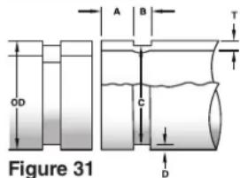
Table II. Standard Roll Groove Specifications ^(1)
NOTE: All Dimensions are in Inches.
| NOM. PIPE SIZE | PIPE DIAMETER | T MIN. WALL THK. | A GASKET SEAT +.015/-.030 | B GROOVE WIDTH +.030/-.015 | C GROOVE DIAMETER | D NOM. GROOVE DEPTH^(2) | ||
| O.D. | TOL. | O.D. | TOL. | |||||
| 1 | 1.315 | +.013 -.013 | 0.065 | 0.625 | 0.281 | 1.190 | +.000 | 0.063 |
| 1^1/4 | 1.660 | +.016 -.016 | 0.065 | 0.625 | 0.281 | 1.535 | +.000 -.015 | 0.063 |
| 1^1/2 | 1.900 | +.019 -.019 | 0.065 | 0.625 | 0.281 | 1.535 | +.000 -.015 | 0.063 |
| 2 | 2.375 | +.024 -.016 | 0.065 | 0.625 | 0.344 | 2.250 | +.000 -.015 | 0.063 |
| 2^1/2 | 2.875 | +.029 -.016 | 0.083 | 0.625 | 0.344 | 2.720 | +.000 -.015 | 0.078 |
| 3 | 3.50 | +.035 -.031 | 0.083 | 0.625 | 0.344 | 3.344 | +.000 -.015 | 0.078 |
| 3^1/2 | 4.00 | +.040 -.031 | 0.083 | 0.625 | 0.344 | 3.834 | +.000 -.020 | 0.083 |
| 4 | 4.50 | +.045 .031 | 0.083 | 0.625 | 0.344 | 4.334 | +.000 -.015 | 0.083 |
| 5 | 5.563 | +.056 .031 | 0.109 | 0.625 | 0.344 | 5.395 | +.000 -.015 | 0.084 |
| 6 | 6.625 | +.063 -.031 | 0.109 | 0.625 | 0.344 | 6.455 | +.000 -.015 | 0.085 |
| 8 | 8.625 | +.063 -.031 | 0.109 | 0.750 | 0.469 | 8.441 | +.000 -.020 | 0.092 |
| 10 | 10.75 | +.063 -.031 | 0.134 | 0.750 | 0.469 | 10.562 | +.000 -.025 | 0.094 |
| 12 | 12.75 | +.063 -.031 | 0.156 | 0.750 | 0.469 | 12.531 | +.000 -.025 | 0.110 |
(1) As per AWWA C606-15
(2) Nominal Groove Depth is provided as a reference dimension only. Do not use groove depth to determine acceptability of a groove.
NOTE: Follow fitting manufacturer's recommendations regarding maximum allowable flare dimension.
Table III. Copper Roll Groove Specifications
NOTE: All Dimensions are in Inches.
| Nom. Size Inches | A Tubing Outside Diameter O.D. Seal A | B Gasket Width Dia. ±0.03 | C Groove Groove Allow. +.03 / -.000 | D Groove Allow. +.000 / -.020 | T Depth (2) | Nominal Wall Thick. (3) | Min. Flare Dia. | |
| Basic | Tolerance | |||||||
| 2 | 2.125 | ±0.002 | 0.610 | 0.300 | 2.029 | 0.048 | 0.064 | 2.220 |
| 2^1/2 | 2.625 | ±0.002 | 0.610 | 0.300 | 2.525 | 0.050 | 0.065 | 2.720 |
| 3 | 3.125 | ±0.002 | 0.610 | 0.300 | 3.025 | 0.050 | 0.045 | 3.220 |
| 4 | 4.125 | ±0.002 | 0.610 | 0.300 | 4.019 | 0.053 | 0.058 | 4.220 |
| 5 | 5.125 | ±0.002 | 0.610 | 0.300 | 5.019 | 0.053 | 0.072 | 5.220 |
| 6 | 6.125 | ±0.002 | 0.610 | 0.300 | 5.999 | 0.063 | 0.083 | 6.220 |
(1) Copper Tubing to the following standards: ASTM B88 & ASTM B306.
(2) Nominal Groove Depth is provided as a reference dimension. Do not use groove depth to determine groove acceptability.
(3) "DWV" – ASTM B306 Drain Waste & Vent Tubing wall thickness.
Rainureuse à galets
natural_image
Industrial machine with tripod base and mechanical components, no visible text or symbolsAVERTISSEMENT!
natural_image
Mechanical device with attached components and wiring (no visible text or symbols)natural_image
Close-up of industrial machinery components including rollers, springs, and a motor (no visible text or symbols)Figure 6 – Avertissements
natural_image
Person operating a precision machine with visible mechanical components (no text or symbols)natural_image
Close-up of mechanical components with no visible text or symbolsnatural_image
Mechanical device with articulated legs and a small rectangular component attached (no visible text or symbols)natural_image
Person operating a mechanical tool with hoses and tools (no visible text or symbols)natural_image
Close-up of a hand operating a mechanical tool on a lathe, no visible text or symbolsnatural_image
Close-up of a mechanical tool with visible gears and levers (no text or symbols)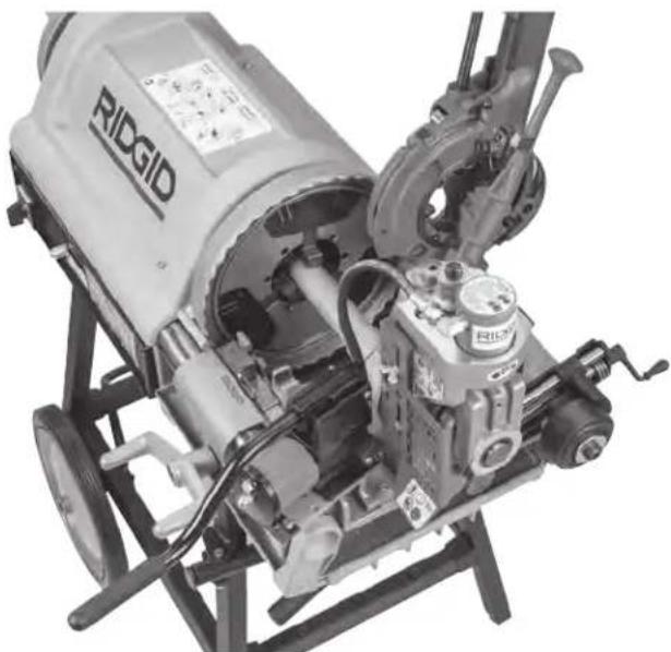
natural_image
Close-up of a mechanical engine component with visible gears and shafts (no text or symbols)natural_image
Two identical industrial electrical modules labeled 918, showing internal components and wiring (no readable text or symbols beyond labels)natural_image
Mechanical assembly diagram showing a mechanical component with gears and shafts (no visible text or symbols)natural_image
Mechanical device with mounted cylindrical body and tripod base, no visible text or symbolsFigure 17A – Place Correct Step of Gauge Under Adjusting Head
natural_image
Close-up of a mechanical clamp or caliper component with circular and square features (no visible text or symbols)Figure 17B – Jauge en position de rainurage
natural_image
Man operating a large mechanical device on a tripod stand, no visible text or symbolsnatural_image
Man operating a large industrial machine on a tripod stand (no visible text or symbols)natural_image
Man operating a long industrial machine on a tripod stand (no visible text or symbols)natural_image
Close-up of a hand measuring a black pipe with a ruler, showing measurement markings (no text or symbols)natural_image
Two industrial mechanical components with visible gears and shafts, no text or symbols present.natural_image
Close-up of a mechanical assembly with a black cylindrical component and two bolts (no visible text or symbols)AVIS IMPORTANT acement, assu-
natural_image
Close-up of a mechanical device with a hand adjusting a cable, no visible text or symbolsnatural_image
Close-up of a hand operating a mechanical assembly with gears and shafts (no visible text or symbols)natural_image
Close-up of hands operating a mechanical device with a cylindrical component (no visible text or symbols)natural_image
Close-up of hands operating a mechanical press or clamp device with no visible text or symbolsnatural_image
Close-up of a hand using a tool to adjust or install a mechanical component, no visible text or symbolsnatural_image
Industrial machine with tripod base and mechanical components, no visible text or symbols
ADVERTENCIA!
natural_image
Mechanical device with attached motor and clamping mechanism (no visible text or symbols)natural_image
Close-up of industrial machinery components including rollers, springs, and a mesh chamber (no visible text or symbols)natural_image
Person operating a mechanical device with a tool, no visible text or symbolsnatural_image
Close-up of mechanical components with no visible text or symbolsnatural_image
Mechanical device with articulated legs and a small rectangular component attached (no visible text or symbols)natural_image
Person operating a mechanical tool with visible wiring and components (no text or symbols)natural_image
Close-up of a hand operating a mechanical tool with visible wiring and components (no text or symbols)natural_image
Industrial machine with visible components and wiring, no text or symbols presentFigura 10 – La ranuradora 918 instalada sobre la roscadora 535 A y la roscadora 1224
natural_image
Close-up of a RIDGID industrial machine with visible internal components and mounting brackets (no text or symbols)Figura 10 – La ranuradora 918 instalada sobre la roscadora 535 A y la roscadora 1224
Operación
ADVERTENCIA


natural_image
Two identical industrial electrical modules labeled 918, showing internal components and wiring (no readable text or symbols beyond labels)natural_image
Mechanical assembly diagram showing a mechanical component with gears and shafts (no text or symbols visible)natural_image
Mechanical device with mounted cylindrical body and tripod stand (no visible text or symbols)natural_image
Close-up of a mechanical clamp or caliper component with no visible text or symbolsnatural_image
Man operating a large mechanical device on a tripod stand, no visible text or symbolsnatural_image
Man operating a large cylindrical mechanical device on a tripod stand (no visible text or symbols)natural_image
Man operating a long industrial machine on a tripod stand, no visible text or symbolsnatural_image
Close-up of a hand measuring a cylindrical pipe with a tape measure, showing no text or symbols on the pipe itself.natural_image
Two industrial mechanical components with visible springs and housing (no text or symbols)Figura 23 – Puntos de engrase
natural_image
Close-up of a mechanical assembly with a circular component and bolts (no visible text or symbols)Figura 24 – Tapa del depósito
natural_image
Close-up of a mechanical tool with a hand adjusting a cable, no visible text or symbolsnatural_image
Close-up of a hand operating a mechanical assembly with gears and shafts (no visible text or symbols)natural_image
Close-up of hands operating a mechanical device with a tool, no visible text or symbolsnatural_image
Close-up of hands operating a mechanical tool with a wrench, no visible text or symbolsnatural_image
Close-up of a hand using a tool to adjust or install a mechanical component, no visible text or symbols| Diám. nominal del tubo | Diám. del tubo mín. de | T Espesor junta obturadora la pared | A Asiento de la ranura +0,015/-0,030 | B Ancho de +0,030/-0,015 | C Diám. en la ranura | D Profundidad nom. de la ranura (2) | ||
| DE | Tol. | DE | Tol. | |||||
| 1 | 1,315 | +0,013 -0,013 | 0,065 | 0,625 | 0,281 | 1,190 | +0,000 | 0,063 |
| 1^1/4 | 1,660 | +0,016 -0,016 | 0,065 | 0,625 | 0,281 | 1,535 | +0,000 -0,015 | 0,063 |
| 1^1/2 | 1,900 | +0,019 -0,019 | 0,065 | 0,625 | 0,281 | 1,535 | +0,000 -0,015 | 0,063 |
| 2 | 2,375 | +0,024 -0,016 | 0,065 | 0,625 | 0,344 | 2,250 | +0,000 -0,015 | 0,063 |
| 2^1/2 | 2,875 | +0,029 -0,016 | 0,083 | 0,625 | 0,344 | 2,720 | +0,000 -0,015 | 0,078 |
| 3 | 3,50 | +0,035 -0,031 | 0,083 | 0,625 | 0,344 | 3,344 | +0,000 -0,015 | 0,078 |
| 3^1/2 | 4,00 | +0,040 -0,031 | 0,083 | 0,625 | 0,344 | 3,834 | +0,000 -0,020 | 0,083 |
| 4 | 4,50 | +0,045 0,031 | 0,083 | 0,625 | 0,344 | 4,334 | +0,000 -0,015 | 0,083 |
| 5 | 5,563 | +0,056 0,031 | 0,109 | 0,625 | 0,344 | 5,395 | +0,000 -0,015 | 0,084 |
| 6 | 6,625 | +0,063 -0,031 | 0,109 | 0,625 | 0,344 | 6,455 | +0,000 -0,015 | 0,085 |
| 8 | 8,625 | +0,063 -0,031 | 0,109 | 0,750 | 0,469 | 8,441 | +0,000 -0,020 | 0,092 |
| 10 | 10,75 | +0,063 -0,031 | 0,134 | 0,750 | 0,469 | 10,562 | +0,000 -0,025 | 0,094 |
| 12 | 12,75 | +0,063 -0,031 | 0,156 | 0,750 | 0,469 | 12,531 | +0,000 -0,025 | 0,110 |
natural_image
Industrial machine with tripod base and mechanical components, no visible text or symbols
WARNUNG!
natural_image
Mechanical device with attached components, possibly a hydraulic or pneumatic pump (no visible text or symbols)natural_image
Close-up of a mechanical assembly with gears and rollers (no visible text or symbols)natural_image
Person operating a mechanical tool with a gear assembly (no visible text or symbols)natural_image
Close-up of mechanical components with no visible text or symbolsnatural_image
Close-up of a mechanical device with two legs and a small connector (no visible text or symbols)natural_image
Person operating a mechanical tool with visible wiring and components (no text or symbols)natural_image
Close-up of a robotic arm with a hand adjusting a mechanical component (no visible text or symbols)natural_image
Two views of a RRDGID industrial machine with visible internal components and no text or symbols on the device itself.natural_image
Two identical industrial electrical modules labeled 918, showing wiring and components (no readable text or symbols beyond labels)natural_image
Mechanical assembly diagram showing a shaft, bearing housing, and mounting bracket (no text or symbols visible)natural_image
Mechanical device with mounted cylindrical body and tripod stand (no visible text or symbols)natural_image
Close-up of a mechanical device with circular components and a central dial (no visible text or symbols)natural_image
Man operating a large industrial machine on a tripod stand (no visible text or symbols)natural_image
Man operating a large industrial machine on a tripod stand (no visible text or symbols)natural_image
Man operating a long industrial machine on a tripod stand, no visible text or symbolsnatural_image
Close-up of a hand measuring a black pipe with a tape measure, showing measurement markings (no text or symbols on the pipe itself)natural_image
Two industrial mechanical components with visible springs and shafts, no text or symbols present.natural_image
Close-up of a mechanical assembly with a black circular component and two bolts (no visible text or symbols)natural_image
Close-up of a mechanical device with a hand adjusting a cable, no visible text or symbolsnatural_image
Close-up of a hand operating a mechanical assembly with gears and shafts (no visible text or symbols)natural_image
Close-up of hands operating a mechanical device with no visible text or symbolsnatural_image
Close-up of hands operating a metal mechanical device with a wrench, no visible text or symbolsnatural_image
Close-up of a mechanical assembly with hands adjusting components (no visible text or symbols)RIDGID® tools are warranted to be free of defects in workmanship and material.
How long coverage lasts
This warranty lasts for the lifetime of the RIDGID® tool. Warranty coverage ends when the product becomes unusable for reasons other than defects in workmanship or material.
How you can get service
To obtain the benefit of this warranty, deliver via prepaid transportation the complete product to RIDGID c/o Emerson Professional Tools, LLC in, Elyria, Ohio, or any RIDGID® AUTHORIZED INDEPENDENT SERVICE CENTER. Pipe wrenches and other hand tools should be returned to the place of purchase.
What we will do to correct problems
Warranted products will be repaired or replaced, at RIDGID's option, and returned at no charge; or, if after three attempts to repair or replace during the warranty period the product is still defective, you can elect to receive a full refund of your purchase price.
What is not covered
Failures due to misuse, abuse or normal wear and tear are not covered by this warranty. Seller is not responsible for any incidental or consequential damages.
How local law relates to the warranty
Some states do not allow the exclusion or limitation of incidental or consequential damages, so the above limitation or exclusion may not apply to you. This warranty gives you specific rights, and you may also have other rights, which vary, from state to state, province to province, or country to country.
No other express warranty applies
This FULL LIFETIME WARRANTY is the sole and exclusive warranty for RIDGID ^® products. No employee, agent, dealer, or other person is authorized to alter this warranty or make any other warranty on behalf of the RIDGID.
To obtain further warranty information on your product please visit www.RIDGID.com/us/en/warranty

Parts are available online at Store.RIDGID.com
RIDGID
Emerson Professional Tools, LLC
400 Clark Street
Elyria, Ohio 44035-6001
U.S.A.