
141 - Machine Tool RIDGID - Free user manual and instructions
Find the device manual for free 141 RIDGID in PDF.
| Product Type | Gear-driven Threading Machine |
| Brand | RIDGID |
| Model | 141 |
| Threading Capacity (NPT) | 1½ to 4 inches (65 to 100 mm) |
| Threading Capacity (BSPT) | 2½ to 4 inches (65 to 100 mm) |
| Threads per Inch (NPT) | 8 |
| Threads per Inch (BSPT) | 11 |
| Weight | 93 lb (42.2 kg) |
| Thread Types | Straight (NPSM, BSPP) and Tapered (NPT, BSPT) |
| Main Functions | Threading of black or galvanized steel pipes, with anti-lock disengagement system |
| Usage Modes | Manual (D-1440 ratchet wrench) or motorized (840A universal drive shaft or direct mount on RIDGID drive systems) |
| Maintenance and Cleaning | Clean after each use, lubricate monthly with light mineral oil and lithium grease for the gearbox |
| Lubrication During Use | RIDGID cutting oil (flood the dies) |
| Safety | Eye protection mandatory, no wearing gloves, use of a foot pedal for emergency stop |
| Spare Parts and Repairability | Dies, jaw plates, drive shafts, gear grease; repair by RIDGID authorized service |
| Warranty | Lifetime (tool lifespan), covers material defects and workmanship |
| Included Accessories | Quick-change die set, hold-down wrench, instruction manual |
Frequently Asked Questions - 141 RIDGID
User questions about 141 RIDGID
0 question about this device. Answer the ones you know or ask your own.
Ask a new question about this device
Download the instructions for your Machine Tool in PDF format for free! Find your manual 141 - RIDGID and take your electronic device back in hand. On this page are published all the documents necessary for the use of your device. 141 by RIDGID.
USER MANUAL 141 RIDGID
Read this Operator's Manual carefully before using this tool. Failure to understand and follow the contents of this manual may result in electrical shock, fire and/or serious personal injury.
Table of Contents
Safety Symbols 2
General Safety Information
Work Area Safety. 2
Electrical Safety .2
Personal Safety .2
Tool Use And Care .3
Service .3
Receding Geared Threaders SafetyWarnings 3
Description, Specifications and Standard Equipment 4
Description.. 4
Specifications. 4
Standard Equipment .5
Pre-Operation Inspection 5
Adjusting the Geared Threaders
Pipe Size Adjustment 5
Thread Size Adjustment .6
Adjusting for Straight or Tapered Threads .6
Changing Dies .6
Set-Up and Operation 7
Stationary Pipe Set-Up. 7
Threading with D-1440 Ratchet .8
Threading with 840A Universal Driveshaft (Rear Mount) .9
Rotating Pipe (Front Mount/Close Coupled) Set-Up 10
Setting Up 300/300A Power Drive Close Coupled to 141/161 Geared Threader 10
Setting up 535, 300 Compact or 1233 Close coupled to 141 Geared Threader 11
Setting up 535A Close Coupled to 141 Geared Threader 12
Threading with a Close Coupled Geared Threader (Front Mount) 13
Inspecting Threads 14
Maintenance Instructions. 15
Cleaning. 15
Lubrication. 15
Accessories 15
Thread Cutting Oil Information 15
Machine Storage 15
Service And Repair 15
Disposal 15
Troubleshooting 16
Lifetime Warranty . Back Cover
*Original Instructions - English
Receding Geared Threaders
Model 141/161
Safety Symbols
In this operator's manual and on the product, safety symbols and signal words are used to communicate important safety information. This section is provided to improve understanding of these signal words and symbols.

This is the safety alert symbol. It is used to alert you to potential personal injury hazards. Obey all safety messages that follow this symbol to avoid possible injury or death.

DANGER
DANGER indicates a hazardous situation which, if not avoided, will result in death or serious injury.

WARNING
WARNING indicates a hazardous situation which, if not avoided, could result in death or serious injury.

CAUTION
CAUTION indicates a hazardous situation which, if not avoided, could result in minor or moderate injury.
NOTICE
NOTICE indicates information that relates to the protection of property.

This symbol means read the operator's manual carefully before using the equipment. The operator's manual contains important information on the safe and proper operation of the equipment.
This symbol indicates the risk of fingers, legs, clothes and other objects catching and/or wrapping on rotating shafts causing crushing or striking injuries.

This symbol indicates the risk of machine tipping, causing striking or crushing injuries.

This symbol means do not wear gloves while operating this machine to reduce the risk of entanglement.

This symbol indicates the risk of fingers, hands, clothes and other objects catching on or between gears or other rotating parts and causing crushing injuries.
This symbol indicates the risk of fingers, legs, clothes and other objects catching and/or wrapping on rotating shafts causing crushing or striking injuries
General Safety Information
WARNING
Read all safety warnings and instructions. Failure to follow the warnings and instructions may result in electric shock, fire and/or serious injury.
SAVE ALL WARNING AND INSTRUCTIONS FOR FUTURE REFERENCE!
Work Area Safety
- Keep your work area clean and well lit. Cluttered or dark areas invite accidents.
- Do not operate tools in explosive atmospheres, such as in the presence of flam mable liquids, gases, or dust. Tools create sparks which may ignite the dust or fumes.
- Keep children and by-standers away while operating a power tool. Distractions can cause you to lose control.
Electrical Safety
- Power tool plugs must match the outlet. Never modify the plug in any way. Do not use any adapter plugs with earthed (grounded) power tools.
Un modified plugs and matching outlets will reduce risk of electric shock.
- Avoid body contact with earthed or grounded surfaces such as pipes, radiators, ranges and refrigerators. There is an increased risk of electrical shock if your body is earthed or grounded.
- Do not abuse the cord. Never use the cord for carrying, pulling or unplugging the power tool. Keep cord away from heat, oil, sharp edges or moving parts. Damaged or entangled cords increase the risk of electric shock.
- When operating a tool outdoors, use an extension cord suitable for outdoor use. Use of a cord suitable for outdoor use reduces the risk of electric shock.
- If operating a power tool in a damp location is unavoidable, use a ground fault circuit interrupter (GFCI) protected supply. Use of a GFCI reduces the risk of electric shock.
Personal Safety
- Stay alert, watch what you are doing and use common sense when operating equipment. Do not use a tool while you are tired or under the influence of
drugs, alcohol, or medication. A mo ment of inattention while operating equipment may result in serious personal injury.
- Dress properly. Do not wear loose clothing or jewel ry. Keep your hair, clothing, and gloves away from moving parts. Loose clothes, jewelry, or long hair can be caught in moving parts.
- Remove any adjusting key or wrench before turning the power tool ON. A wrench or a key left attached to a rotating part of the power tool may result in personal injury.
- Do not overreach. Keep proper footing and balance at all times. This enables better control of the equipment in unexpected situations.
- Use personal protective equipment. Always wear eye protection. Protective equipment such as dust mask, non-skid safety shoes, hard hat, or hearing protection used for appropriate conditions will reduce personal injuries.
Tool Use And Care
- Do not force the tool. Use the correct tool for your application. The correct tool will do the job better and safer at the rate for which it is designed.
- Do not use tool if the switch does not turn it ON and OFF. Any tool that cannot be controlled with the switch is dangerous and must be repaired.
- Disconnect the plug from the power source before making any adjustments, changing accessories, or storing the tool. Such preventive safety measures reduce the risk of starting the tool accidentally.
- Store idle power tools out of the reach of children and do not allow persons unfamiliar with the power tool or these instructions to operate the tool. Tools are dangerous in the hands of untrained users.
- Maintain tools. Check for misalignment or binding of moving parts, breakage of parts and any other condition that may affect the power tool's operation. If damaged, have the tool repaired before use. Many accidents are caused by poorly maintained power tools.
- Keep cutting tools sharp and clean. Properly maintained cutting tools with sharp cutting edges are less likely to bind and are easier to control.
- Use only accessories that are recommended by the manufacturer for your model. Accessories that may be suitable for one tool may become hazardous when used on another tool.
Service
- Tool service must be performed only by qualified repair personnel. Service or maintenance performed by unqualified personnel could result in a risk of injury.
- When servicing a tool, use only identical replacement parts. Follow instructions in the Maintenance section of this manual. Use of unauthorized parts or failure to follow Maintenance Instructions may create a risk of electrical shock or injury.
Specific Safety Information
WARNING
This section contains important safety information that is specific to this tool.
Read these precautions carefully before using Model 141/161 Receding Geared Threaders to reduce the risk of electrical shock or other serious injury.
SAVE THESE INSTRUCTIONS!
Keep this manual with machine for use by the operator.
Receding Geared Threaders Safety
- Do not wear gloves or loose clothing when operating machine. Keep sleeves and jackets buttoned. Do not reach across the machine or pipe. Clothing can be caught by the pipe or machine resulting in entanglement.
- Keep hands away from rotating pipe and fittings. Stop the machine before wiping pipe threads or screwing on fittings. Allow the machine to come to a complete stop before touching the pipe. This practice will reduce the chance of entanglement in rotating parts.
- Guard or barricade minimum of one (1) meter a round the area when work piece extends beyond machine. A guard or barricade that provides a clearance around the work piece will reduce the risk of entanglement.
- One person must control the work process, threading machine operation and foot switch. Only the operator should be in the work area when the machine is running. This helps reduce the risk of injury.
- Secure machine to bench or stand. Support long heavy pipe with pipe supports. This practice will reduce the risk of tipping.
-
Keep floor dry and free of slippery materials such as oil. Slippery floors invite accidents.
-
Follow instructions on proper use of this machine. Do not use for other purposes such as drilling holes or turning winches. Other uses or modifying this power drive for other applications may increase the risk of serious injury.
- Read and understand the instructions and warnings for all equipment being used including Threading Machines and Power Drives before operating the Geared Threaders. Failure to follow all warnings and instructions may result in property damage and/or serious injury.
- Do not use this machine if the foot switch is broken or missing. Foot switch is a safety device that provides better control by letting you shut off the motor in various emergency situations by removing your foot from the switch. For example: if clothing should become caught in the machine, the high torque will continue pulling you into the machine. The clothing itself can bind around your arm or other body parts with enough force to crush or break bones.
The EC Declaration of Conformity (890-011-320.10) will accompany this manual as a separate booklet when required.
If you have any question concerning this RIDGID® product:
-
Contact your local RIDGID distributor.
-
Visit www.RIDGID.com to find your local RIDGID contact point.
- Contact RIDGID Technical Services Department at rtctechservices@emerson.com, or in the U.S. and Canada call (800) 519-3456.
Description, Specifications and Standard Equipment
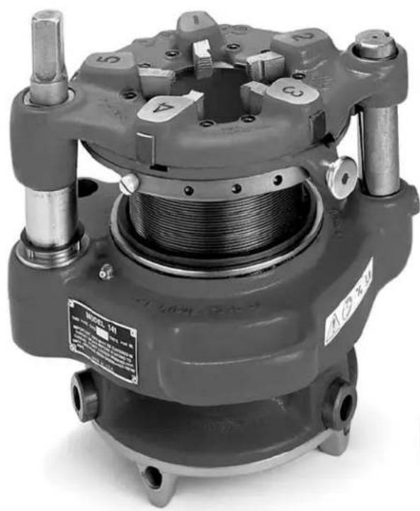
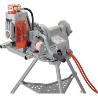
Description
The RIDGID Model 141 and 161 Recoding Geared Threaders are designed to thread 2/2'' to 4'' and 4'' to 6'' pipe, respectively. A cam type workholder is used to grip the pipe while the die head cuts the threads. A clutch is included to prevent jamming at the end of the thread. The threaders can be used for both tapered and straight right hand threads with a simple adjustment. See specifications for NPT and BSPT versions.
The 141 and 161 can be powered in a variety of ways, including operation by hand or with various RIDGID Threading Machines and Power Drives.
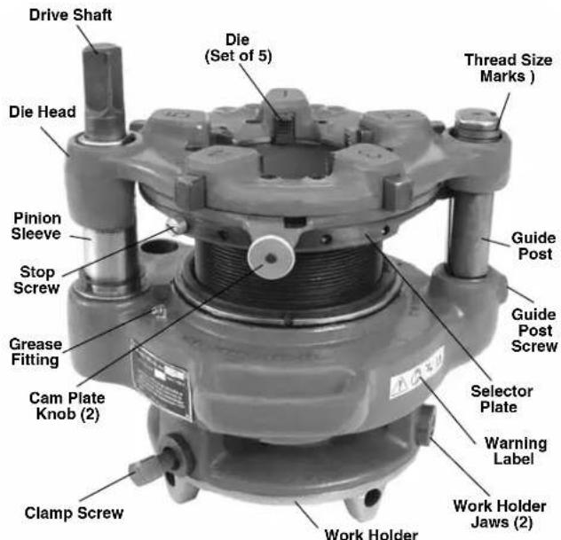
Figure 1 - Model 141 Recoding Geared Threader
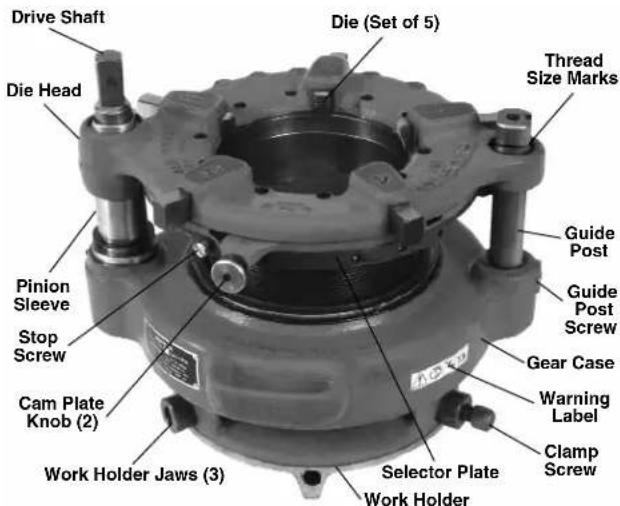
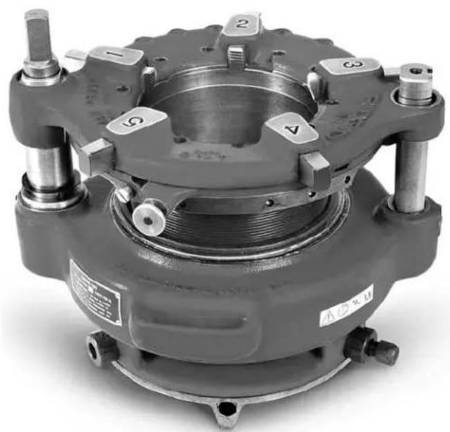
Figure 2 - Model 161 Recoding Geared Threader
Specifications
| Model No. | Thread Type Threads | Per Inch | Nominal Capacity Weight | |||
| inch mm lb kg | ||||||
| 141 NPT | 8 2½ to 4 65 to 100 | 93 42.2 | ||||
| 141 | BSPT | 11 | 2½ to 4 65 to 100 | 93 42.2 | ||
| 161 NPT | 8 | 4 to 6 100 to 150 | 158 | 71.7 | ||
Standard Equipment
The Model 141/161 Recoding Geared Threaders come with the following items:
- One set of High Speed Dies
- Wrench for Workholder Clamp
Operator's Manual
NOTICE Selection of appropriate materials and joining methods is the responsibility of the system designer and/or installer. Before any installation is attempted, careful evaluation of the specific service environment, including chemical environment and service temperature should be completed.
Pre-Operation Inspection
WARNING
Before each use, inspect your geared threads and correct any problems to reduce the risk of serious injury from electrical shock, crushing injuries and other causes and prevent machine damage.
- If the geared threads are attached to a threading machine or a power drive, make sure the equipment is unplugged and the directional switch is set to OFF position.
- Clean any oil, grease or dirt from the geared threader, including the handles and controls. This aids inspection and helps prevent the tool or control from slipping from your grip. If necessary, clean the work holder jaws with a wire brush. Remove metal shavings and chips from the die head.
-
Inspect the geared threaders for the following items:
-
Proper assembly and completeness.
- Broken, damaged, missing, misarranged or binding parts.
- Presence and readability of warning label (see Figures 1 and 2).
- Any other condition that may prevent the safe and normal operation.
If any problems are found, do not use the geared threader until the problems have been repaired.
- Inspect the cutting edges of dies for deformation, chips or other issues. Dull or damaged cutting tools increase the amount of force required, produce poor quality threads and increase the risk of injury.
-
If necessary, lubricate the geared threader per the maintenance instructions. Wipe any excess lubricant from the equipment.
-
Inspect and maintain any other equipment being used per its instructions to make sure it is functioning properly.
If using a threading machine or power drive, make sure that the foot switch is attached to the machine and that it and the cord are in good condition. Press the foot switch pedal and confirm that it cycles smoothly and does not stick.
Do not use threading machines or power drives that do not function properly.
Adjusting the Geared Threaders
WARNING
Adjust the geared threaders according to these procedures to reduce the risk of injury and to help prevent equipment damage.
The Receding Geared Threaders can be adjusted for different thread size and types. Model 141 Threader can thread 2^1 / 2 , 3^ , 3^1 / 2 and 4^ pipes with NPT or BSPT threads, while Model 161 Threader can thread 4^ , 4^1 / 2 , 5^ and 6^ NPT threads. The threads can also be adjusted for tapered or straight threads.
Always cut a test thread to confirm proper thread size after adjusting the geared threaders.
Pipe Size Adjustment
- Place the geared threadser with drive shaft/die head up.
- Pull out the cam plate knobs and rotate cam plate to correct size for the application as marked on top of the die head. Release knobs to lock in place.
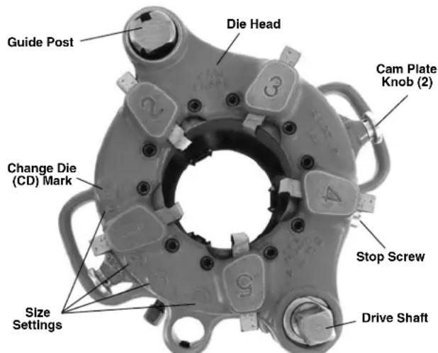
Figure 3 - Geared Threader With Drive Shaft Up (Model 141 shown)
Thread Size Adjustment
With the drive shaft/die head of geared threader up, turn the drive shaft or gear case by hand. Align the die head with appropriate starting point marks on the guide post or pinion sleeve (see Figure 4). The thread size needs to be set before every thread to insure proper thread size.
- Standard Size Thread - either set bottom of the die head flush with the red standard line on the pinion sleeve, or set the upper surface of die head flush with the centerline on the guide post.
- Oversize thread (larger diameter, less turns of fitting engagement) - set upper surface of the die head flush with the bottom line on the guide post. That line is marked "2T OVER".
- Undersize thread (smaller diameter, more turns of fitting engagement) - set upper surface of the die head flush with the top line on the guide post. That line is marked "2T UNDER".
Threader can be adjusted to any point in between as desired.
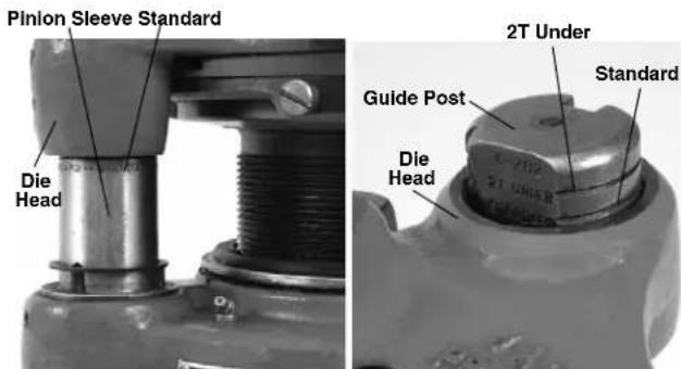
Figure 4 - Thread Size Adjustment - Close-Ups of Pinion Sleeve and Guide Post Markings
Adjusting for Straight or Tapered Threads
Geared threaders are factory set to make tapered threads (NPT or BSPT), and can be adjusted to cut straight threads (NPSM or BSPP). Tapered threads are made with the guide block engaged in the angled slot in the guide post. Straight threads are made with the guide block engaged in the straight slot in the guide post.
- Adjust the geared threader to cut a standard size thread (see above).
- Remove screw from gear case at the base of guide post.
- Pull the guide post up until guide block (attached to selector plate) is disengaged from the slot in the guide post.
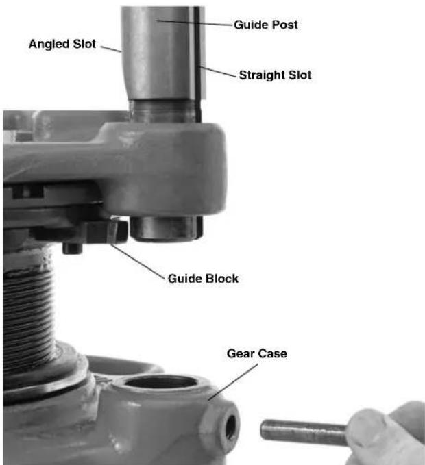
Figure 5 - Adjusting For Straight or Tapered Threads
- Turn the guide post until appropriate slot (angled for tapered threads, straight for straight threads) faces inward and is aligned with the guide block.
- Engage guide block in the guide post slot and push the guide post down into the gear case.
- Reinstall the screw in the gear case at the base of guide post.
Changing Dies
Geared threaders are marked with the number of threads per inch on the nameplate. The threaded barrel for an NPT geared threader has 8 threads per inch, while a BSPT geared threader has 11 threads per inch.
NOTICE Do not use BSPT dies in NPT threads and vice versa. This will cause incorrect threads and may damage dies and/or geared threaders
- Place the geared threads with drive shaft/die head up.
- Remove stop screw from the selector plate (Figure 3).
- Pull cam plate knobs out and rotate cam plate to "CD" mark on top of the die head.
- Remove the existing dies from the die head.
- Insert correct dies for the application into the slots. The numbers on the dies (1-5) must correspond with the
numbers over the die head slot. Fully insert the die with the numbered side up.
- Pull out the cam plate knobs and rotate cam plate to correct size for the application as marked on the die head. Release knobs to lock in place.
- Replace the stop screw in the selector plate.
Set-Up and Operation
WARNING


Always wear eye protection. Wear steel toe foot - wear to help protect from tipping tools and falling pipe.
Do not wear gloves or loose clothing. Keep sleeves and jackets buttoned. Loose clothing can become entangled in rotating parts and cause crushing and striking injuries.
Keep hands away from rotating pipe and parts. Do not reach across the machine or pipe. To prevent entanglement, crushing or striking injuries, allow equipment to come to a complete stop before touching.
Properly secure the geared threaders to the threading machine/power drive and pipe. Improperly secured tools can slip and fall and cause striking and crushing injuries.
Do not use a power drive or threading machine without a properly operating foot switch. Never block a foot switch in the "ON" position. A foot switch provides better control by letting you shut off the machine motor by removing your foot. If entanglement should occur and power is maintained to the motor, you will be pulled into the machine. This machine has high torque and can cause clothing to bind around your arm or other body parts with enough force to crush or break bones or cause striking or other injuries.
One person must control both the work process and the foot switch. Do not operate with more than one person. In case of entanglement, the operator must be in control of the foot switch.
Set up and operate the geared threads according to these procedures to reduce the risk of injury from machine tipping, entanglement, crushing, striking and other causes, and to help prevent equipment damage.
Geared threads can be used a variety of ways, with the primary difference being whether the pipe is stationary or turns during threading.
If the pipe is held stationary (such as in a pipe vise), the die head end of the geared threader rotates around the pipe during threading. Threading can be done by hand with a D-1440 ratchet or by using an 840A Universal Driveshaft and a threading machine. Use of the 840A driveshaft is often referred to as "rear mount".
Alternatively, geared threads with the proper accessories can be driven by a variety of threading machines. In these cases, the die head end of the geared threader is stationary and the workholder and pipe rotate. This method is often referred to as "front mount" or "close coupled".
Stationary Pipe Set-Up
-
Locate a work area that has:
-
Adequate lighting.
-
Clear level, stable, dry location for all of the equipment and the operator.
-
Clean the work area before setting up any equipment. Wipe up any oils or liquids.
- Inspect the pipe to be threaded and associated fittings and confirm that the 141 or 161 Geared Threader is a correct tool for the job. See the Specifications.
Threading equipment for other applications can be found in the RIDGID catalog on line at www.RIDGID.com or www.RIDGID.eu.
- Confirm that equipment to be used has been properly inspected.
- Make sure that pipe to be threaded is solidly mounted and stable. Pipe and mounting must be able to withstand the weight of the geared threader and the force and torque required for threading without moving or turning. When using a pipe vise, make sure that it is properly sized and secured to prevent tipping during use. Tristands must be bolted to the floor. For longer lengths of pipe, use appropriate pipe stands to support extra length.
- If using with 840A Universal driveshaft, the centerline of the pipe must be at same level as the centerline of threading machine spindle.
- Confirm that the pipe end is squarely cut and reamed/ - de burred. Improperly prepared pipe can chip dies, increase threading force and give improper threads.
- Properly adjust the geared threads for the work to be done. Make sure that the die head is correctly backed off to make an appropriate sized thread. See "Adjust Geared Threaders".
- Use appropriate equipment to lift the geared threader and place over the end of the pipe orienting one jaw
of work-holder upward. Lifting by hand must be done by at least two people utilizing the carrying handles. Be aware that the 141 weighs 93 pounds and the 161 weighs 158 pounds. Carefully center end of pipe in throat of the dies and turn workholder scroll to tighten jaws on pipe. The end of the socket wrench can be inserted in the holes of scroll for tightening. Do not strike the scroll to tighten - this can damage the scroll. Use socket wrench to tighten clamp screw in the jaw. Make sure that the geared threader is secure to the pipe and is stable (Figure 6).
- Place 418 Oiler bucket under the geared threadser, making sure that it has enough clean, RIDGID Thread Cutting Oil.
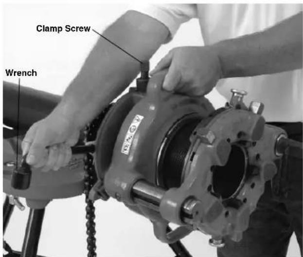
Figure 6 - Tightening Workholder
Threading with D-1440 Ratchet
- Make sure the geared threader is properly set up for stationary pipe operation.
- Place the D-1440 Ratchet on square end of the drive shaft.
- Assume a proper operating stance. Make sure that your footing is good and you are well balanced. For maximum leverage, you will want to use your body weight on the handle of the ratchet. Make sure the set up is stable.
- Use the ratchet to turn the driveshaft. Rotation should be clockwise as viewed from the end of the pipe. Flood the dies with oil while threading to lower threading torque, improve thread quality and increase die life.
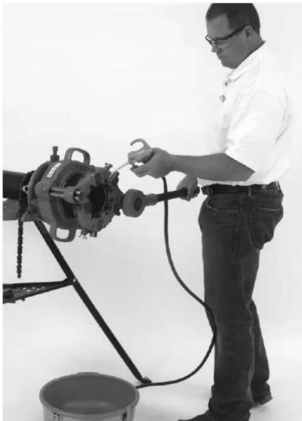
Figure 7 - D-1440 Ratchet Operation
- Continue ratcheting until the top edge of the die head is flush with the red stop line on the pinion sleeve (see Figure 8).
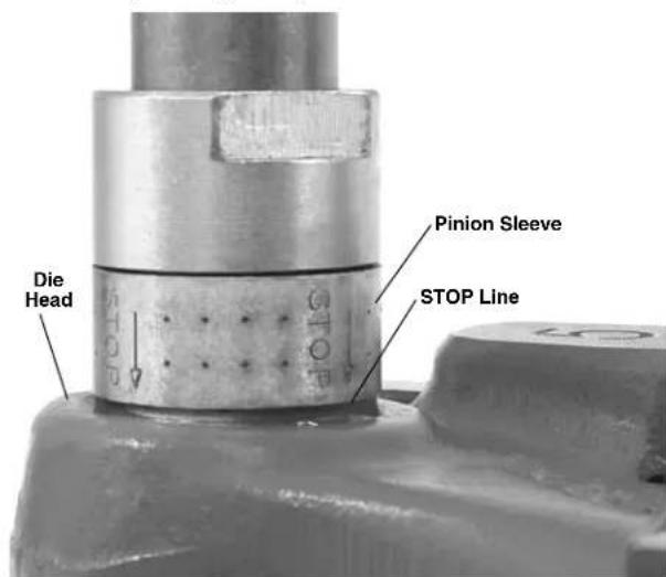
Figure 8 - Thread Complete - Top of Die Head Flush With STOP Line
- Remove the ratchet and turn over. Rotate the driveshaft counterclockwise to back the die head up approximately one turn.
- Pull out cam plate knobs and rotate cam plate towards the "CD" mark on top of the die head to re tract the dies. This prevents the dies from dragging while returning the geared threader to the start position.
- Rotate drive shaft counterclockwise to back the die head to the appropriate starting point for the next thread.
- Carefully remove the geared threads from the pipe and inspect threads.
Threading with 840A Universal Driveshaft (Rear Mount)
Using the 840A Universal Driveshaft, geared threaders can be operated with 300/300A Power Drive, 535 and 1224 Threading Machines.
Do not attempt to use any other threading machine to drive the geared threaders with 840A universal driveshaft. Do not use auto-chucking threading machine (like 535A). Do not use machines that do not have reverse rotation.
- Make sure the geared threader is properly set up for stationary pipe operation.
- Make sure that the threading machine is unplugged and the FOR/OFF/REV switch set to OFF. Follow all warnings and instructions for the threading machine
- Locate the threading machine so that the centerline of the spindle lines up with the centerline of the pipe to be threaded. The rear chuck of the threading machine should be facing the pipe end to be threaded.
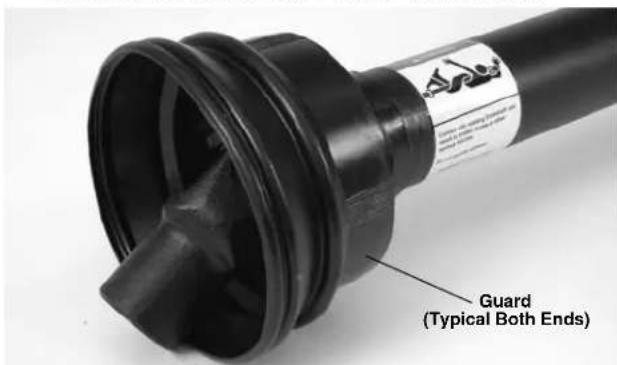
Figure 9 - 840A Driveshaft Guard and Warning
- Insert the hex shaped end of the 840A Driveshaft into the rear centering head of the threading machine. Securely tighten the rear centering head and the front chuck onto the flats of the universal driveshaft.
Do not insert from the front (carriage) end of the machine.
- Align and slip the square socket of the 840A driveshaft over the geared threader driveshaft. Tighten two setscrews securely to hold in place. Make sure that the driveshaft universal joint guards are in place and in good condition (see Figure 9).
- Inspect the position of the sliding shank in the drive-shaft. It should be approximately centered to allow movement in either direction. If needed, slightly adjust the position of the threading machine. The centerline of the threading machine should line up with centerline of the pipe. If they are not aligned, this can cause tipping of the threading machine.

Figure 10 - Set-Up With Universal Driveshaft
- If using a 300/300A Power Drive, secure it to the floor to prevent tipping.
- Set up guards or barricades to create a minimum of one meter (three feet) of clearance around the equipment and pipe. This helps to prevent non-operators from accidentally contacting the machine or pipe and causing tipping or becoming entangled in the rotating parts.
-
Place the foot switch to allow a proper operating position. With dry hands plug in the threading machine and place the threading machine switch in REV position.
-
Assume a proper operating position to help maintain control of the machine and process (see Figure 11).
-
Stand on the FOR/OFF/REV switch side of the threading machine with access to the switch.
- Be sure that you can control the foot switch. Do not step on foot switch yet.
- Be sure that you have good balance and do not have to overreach. Make sure that you are clear of the driveshaft.

Figure 11 - Threading With Universal Driveshaft
- Press the foot switch to start threading. Flood the dies with oil to lower threading torque, improve thread quality and increase die life. The geared threads drive shaft will rotate around the pipe while threading, so be prepared for the movement of the driveshaft. If any problems are experienced step off of foot switch.
- Continue threading until the edge of the die head is flush with the red stop line on the pinion sleeve (Figure 8). Release foot switch. If threading is continued past the red stop line, the pinion shaft will disengage to prevent jamming. Do not continue to operate with the pinion shaft disengaged – over time this can cause tool damage.
- Put the FOR/OFF/REV switch in the FOR position. Resume operating position and step on foot switch to back die head off approximately one turn. Release fooswitch and place FOR/OFF/REV switch in OFF position.
- Pull cam plate knobs out and rotate cam plate towards the "CD" mark on top of the die head to retract the dies. This prevents the dies from dragging while returning the geared threads to the start position.
- Put the FOR/OFF/REV switch in the FOR position. Resume operating position and step on foot switch to rotate the die head to the appropriate starting point for the next thread.
- Remove foot from the foot switch. Place the FOR/ OFF/ REV switch in the OFF position and unplug the threading machine.
NOTICE If the workholder is unscrewed from the threaded barrel, DO NOT try to re-engage the thread under power - this could damage the threads. Remove the geared threads from the pipe and re-engage by hand.
Carefully remove the universal driveshaft and geared threader from the pipe and inspect thread.
Rotating Pipe (Front Mount/Close Coupled) Set-Up
-
Locate a work area that has:
-
Adequate lighting.
-
Clear level, stable, dry location for all of the equipment and the operator.
-
Clean the work area before setting up any equipment. Wipe up any oils or liquids.
- Inspect the pipe to be threaded and associated fittings and confirm that the 141 or 161 Geared Threader is a correct tool for the job. See the Specifications.
Threading equipment for other applications can be found in the RIDGID catalog on line at www.RIDGID.com or www.RIDGID.eu.
- Confirm that equipment to be used has been properly inspected.
- Set up the machine in clear, level space selected for the work area following the threading machine instructions. Check that the machine and stand are stable. Make sure machine is unplugged and FOR/OFF/REV switch is in the OFF position. If using with the 300/300A Power Drive, remove carriage, die head, reamer and cutter from the support bars. If using a threading machine, remove the die head from carriage, place the cutter and reamer up and away, and move the carriage away from the chuck.
- Fully open the front chuck and the rear centering device on the machine.
- Properly adjust the geared threads for the work to be done. Make sure that the die head is correctly backed off to make an appropriate sized thread. See "Adjusting Geared Threaders".
- With the drive shaft of the geared threader up, attach the 844 Drive Bar and securely tighten the two set - screws to retain in place (See Figure 15). For 535A machine, do not attach drive bar at this time.
Setting Up 300/300A Power Drive Close Coupled to 141/161 Geared Threader
- Loosen the retaining ring assembly on the support bars
and fully retract the support bars into the power drive housing.
- Use appropriate equipment to lift the geared threader and place over the end of the pipe orienting one jaw of work-holder upward. Lifting by hand must be done by at least two people utilizing the carrying handles. Be aware that the 141 weighs 93 pounds (42 kg) and the 161 weighs 158 pounds (72 kg). Leave approximately 34 " (19 mm) of the drive bar exposed in front of the chuck to allow space for oiling (Figure 12). Securely tighten chuck jaws into three "V" shaped grooves in the head of drive bar. Close the rear centering head onto drive bar. Make sure that the geared threader and power drive are stable and secure.
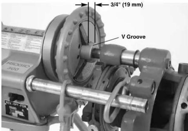
Figure 12 - Locating Drive Bar To Allow Oiling Space
- Model 141 - Loosen set screw in geared threader attachment boss. Install the 758 loop into boss and tighten setscrew to retain loop. Pull switch side support bar forward and through the 758 loop and secure in place with the retaining ring assembly (Figure 13).
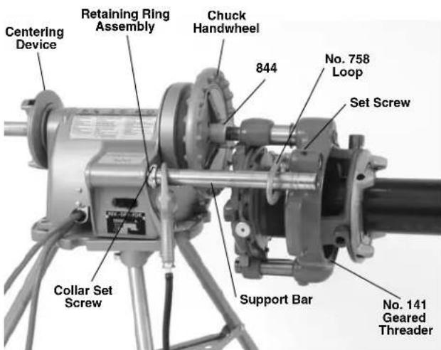
Figure 13 - Model 141 Geared Threader Close-Coupled to Power Drive
Model 161 - Remove setscrew (plug) from threads guide post. Place the 346 support arms inside the ends of the Power Drive support bars. Pull out the Power Drive support bars so the ends of 346 support arms align with the end of 161 Threader guide post and retain with bolt and washer. Tighten the retaining ring assemblies on the Power Drive support bars to hold in place (Figure 14).
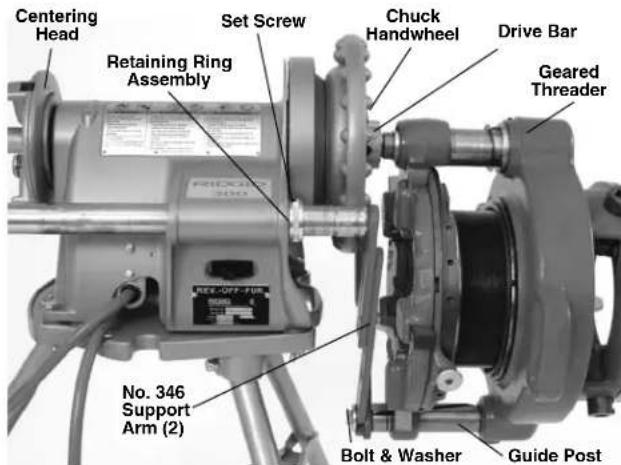
Figure 14 - Model 161 Geared Threader Close-Coupled to Power Drive
Setting up 535, 300 Compact or 1233 Close coupled to 141 Geared Threader
This method can also be used with the 300 and 300A Power Drives when equipped with a carriage. Do not use geared threaders with machines on folding stands. Stand must be in good condition.
- Loosen setscrew in geared threads attachment boss. Install the 768 Drive Link into boss and tighten set screw to retain (Figure 15). Do not over tighten - the drive link should rotate freely.
- If using a 535M with the high clearance carriage, place the leveling saddle on the carriage as shown in Figure 16.
- Use appropriate equipment to lift the geared threader and place. Lifting by hand must be done by at least two people utilizing the carrying handles, be aware that the 141 weighs 93 pounds (42 kg) and the 161 weighs 158 pounds (72 kg). Leave approximately 34 of the drive bar exposed in front of the chuck to allow space for oiling (Figure 12). Securely tighten chuck jaws into three "V" shaped grooves in the head of drive bar. Close the rear centering device onto drive bar. Make sure that the geared threader and power drive are stable and secure.
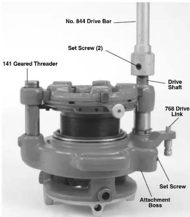
Figure 15 - 844 Drive Bar and 768 Drive Link Installed
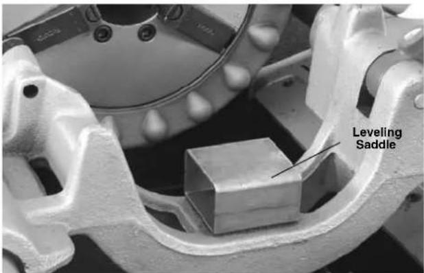
Figure 16 - Saddle on 535 Carriage
- Align the post of 768 drive link with the die head mounting hole in the carriage and fully insert by moving the carriage. Tighten the drive link set screw to hold in place. Make sure that the geared threads and threading machine are stable and secure (Figure 17).
- On machines with oiling systems, install the flexible oil spout on drive link and route so nozzle applies oil between chaser #1 and 2.
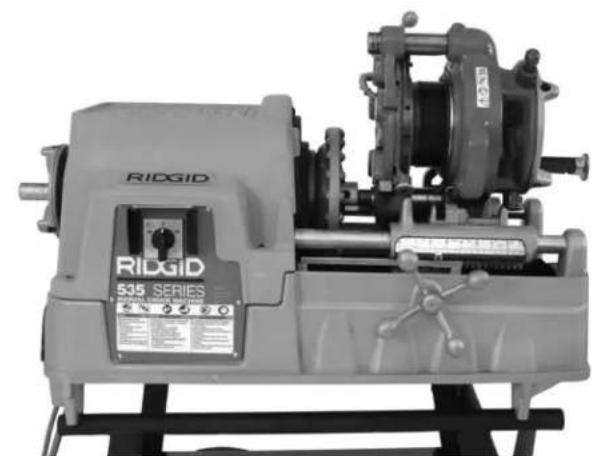
Figure 17 - Geared Threader Close-Coupled To 535
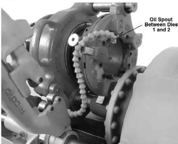
Figure 18 - Flexible Oil Spout Routing
Setting up 535A Close Coupled to 141 Geared Threader
- Place the leveling saddle on the carriage as shown in Figure 16.
- Install the flexible oil spout on 268 drive link.
- Loosen set screw in geared threads attachment boss.
- From the rear of machine, install the drive bar through the spindle tube to the cover (jaws must be fully open). A counterclockwise rotation of the drive bar is required.
-
Using at least two people or appropriate equipment, lift the geared threader, and place on the leveling saddle with the driveshaft of the geared thread lined up with the driveshaft in the threading machine.
-
Fully insert the drive link into the geared threads attachment boss and the die head mounting hole in the carriage.
- From the back of the threading machine, rotate and push the drive bar onto the square drive shaft of the geared threadser. Securely tighten the two setscrews to retain in place. Tighten the drive link set screw.
- Rotate the carriage hand wheel until the geared threader is one inch (25 mm) from the front chuck cover.
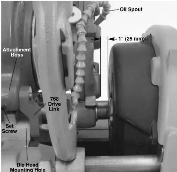
Figure 19-141 Threader Close Coupled To 535A Threading Machine
Threading with a Close Coupled Geared Threader (Front Mount)
- Confirm that the equipment is properly set up.
- Confirm that the pipe end is squarely cut and reamed/ deburred. Improperly prepared pipe can chip dies, increase threading force and give improper threads.
- Support pipe with pipe stands to prevent the pipe and threading machine from tipping or falling. Place the pipe stands in line with workholder. Longer pipe may need multiple pipe stands. Only use pipe stands designed for this purpose. Improper pipe supports or supporting the pipe by hand can cause tipping or entanglement injuries.
- Carefully insert/center end of pipe in throat of the dies. Turn workholder scroll to tighten jaws on pipe. The end of the socket wrench can be inserted in the holes in the
scroll for tightening. Do not strike the scroll to tighten - this can damage the scroll. Use the socket wrench to tighten the clamp screw in the jaw. Make sure that the pipe is secure to the geared thread er and is stable and properly aligned (Figure 20).
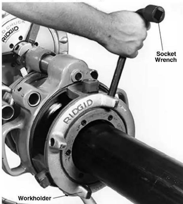
Figure 20 - Tightening Workholder
- If using a 300 Power Drive, place 418 Oiler bucket under the geared threadser. If using 300A Power Drive or a threading machine, route the flexible oil spout so nozzle applies oil between chaser #1 and 2 (Figure 18). Turn the oil spout valve to on position.
- Set up guards or barricades to create a minimum of one meter (three feet) of clearance around the equipment and pipe. This helps to prevent non-operators from accidentally contacting the machine or pipe and causing tipping or becoming entangled in the rotating parts.
- Place the foot switch to allow a proper operating position. With dry hands plug in the threading machine and place the threading machine switch in FOR position.
-
Assume a proper operating position to help maintain control of the machine and process (Figure 21).
-
Stand on the FOR/OFF/REV switch side of the threading machine with access to the switch.
- Be sure that you can control the foot switch. Do not step on foot switch yet.
-
Be sure that you have good balance and do not have to overreach.
-
Press the foot switch to start threading. Flood the dies with oil to lower threading torque, improve thread quality and increase die life (Figure 21).
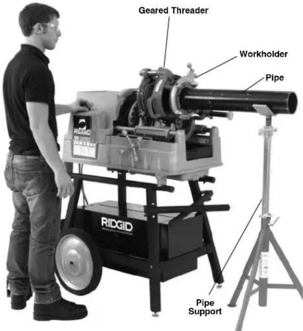
Figure 21 - Operating Position (Close-Coupled Method)
- Continue threading until the edge of die head is flush with the red stop line on the pinion sleeve (Figure 5). Release foot switch. If threading is continued past the red stop line, the pinion shaft will disengage to prevent jamming. Do not continue to operate with the pinion shaft disengaged - over time this can cause tool damage.
- Put the FOR/OFF/REV switch in the REV position. Resume operating position and step on foot switch to back die head off approximately one turn. Release foot switch and place the FOR/OFF/REV switch in OFF position.
- Pull cam plate knobs out and rotate cam plate towards the "CD" mark on top of the die head to retract the dies. This prevents the dies from dragging while returning the geared threader to the start position.
- Put the FOR/OFF/REV switch in the REV position. Resume operating position and step on foot switch to back the die head to the appropriate starting point for the next thread.
- Remove foot from the foot switch. Place the FOR/ - OFF/ REV switch in the OFF position and unplug the threading machine.
- If the workholder is unscrewed from the threaded
barrel, DO NOT try to re-engage the thread under power. Remove the geared threads from the machine and re-engage by hand.
16 Carefully remove the pipe from the geared threads and inspect.
Inspecting Threads
- Remove any oil, chips or debris from the thread.
- Visually inspect the threads. Threads should be smooth and complete, with good form. If issues such as thread tearing or waviness, thin threads, or pipe out-of-roundness are observed, the thread may not seal when made up, especially in pressurized systems. Refer to the "Troubleshooting Chart" to diagnose these issues.
-
Inspect the size of thread. The preferred method of checking thread size is with a ring gauge. There are various styles of ring gauges, and their usage may differ from that described here.
-
Screw ring gauge onto the thread hand tight.
- Look at how far the pipe end extends through the ring gage. The end of pipe should be flush with the side of the gauge plus or minus one turn (Figure 22). If thread does not gauge properly, cut off the thread, adjust the geared threads and cut another thread. Using a thread that does not gauge properly can cause leaks.
- If a ring gauge is not available to inspect thread size, it is possible to use a new clean fitting representative of those used on the job to gauge thread size. The thread should be cut to obtain
2^1/2 to 4^n NPT 5
12 to 6^3 / 4 turns to hand tight engagement with the fitting.
4" to 6" NPT 6
34 to 7^34 turns to hand tight engagement with the fitting.
2^1/2 to 4 BSPT 4 to 4 12 turns to hand tight engagement with the fitting.
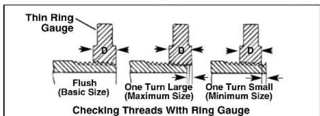
Figure 12 - Checking Thread Size
- Test the system in accordance with local codes and normal practice.
Maintenance Instructions
WARNING
Maintain geared threaders according to these procedures to reduce the risk of injury.
Cleaning
After each use, clean all chips and debris from the geared threaders and wipe off threading oil.
Clean the workholder jaws with a wire brush to remove any build up of pipe scale, etc.
Lubrication
On a monthly basis (or more often if needed).
- Lubricate all exposed moving parts with a light lubricating oil. Wipe any excess oil from exposed surfaces.
- Lubricate the threads with a lithium based general purpose grease at grease fitting (on the gear case near the drive shaft).
Accessories
WARNING
To reduce the risk of serious injury, only use accessories specifically designed and recommended for use with the 141 and 161 Receding Geared Threaders such as those listed below. Other Accessories suitable for use with other tools may be hazardous when used with the 141 and 161 Receding Geared Threaders.
| Catalog No. | Model Description No. | |
| 39380 | D-1440 | Ratchet and Handle |
| 96725 | — Metal | Carrying Case for 141 Geared Threaders |
| 41620 | — Gear | Head Motor Grease |
| 42505 | 46 Adjustable Pipe Support | |
| 61122 | 840A Universal Drive Shaft | |
| 19366 | 758 Loop | (141 with 300/300A Power Drive) |
| 40005 | 346 Support Arms (161 with 300/300A Power Drive) | |
| 42405 | 844 Drive | Bar |
| 42415 | 768 Drive | Link Assembly |
| 97882* | — Kit | 141 on 535 Auto Chuck with High-Clearance Carriage |
| 16723* | — Kit 141 | on 535 Manual Chuck with High-Clearance Carriage |
Further information on accessories specific to this tool can be found in the RIDGID Catalog and online at www.RIDGID.com.
Thread Cutting Oil Information
Read and follow all instructions on the threading oil label and MSDS. Specific information about RIDGID Thread Cutting Oils, including Hazard Identification, First Aid, Fire Fighting, and accidental release measures, Handling and storage, Personal Protective equipment, Disposal and Transportation, is included on the container and Material Safety Data Sheet (MSDS). MSDS is available at www.RIDGID.com or by contacting RIDGID Technical Service Department at (800) 519-3456 in U.S. and Canada or rttechservices@emerson.com.
Machine Storage
NOTICE The Receding Geared Threaders must be kept indoors or well covered in rainy weather. Store the threaders in a locked area that is out of reach of children and people unfamiliar with threading machines. This machine can cause serious injury in the hands of un-trained users.
Service And Repair
WARNING
Improper service or repair can make machine unsafe to operate.
The "Maintenance Instructions" will take care of most of the service needs of this machine. Any problems not addressed by this section should only be handled by an authorized RIDGID service technician.
Tool should be taken to a RIDGID Independent Authorized Service Center or returned to the factory.
For information on your nearest RIDGID Independent Service Center or any service or repair questions:
- Contact your local RIDGID distributor.
- Visit www.RIDGID.com to find your local RIDGID contact point.
- Contact RIDGID Technical Services Department at rtctechservices@emerson.com, or in the U.S. and Canada call (800) 519-3456
Disposal
Parts of the geared threaders contain valuable materials and can be recycled. There are companies that specialize in recycling that may be found locally. Dispose of the components in compliance with all applicable regulations. Contact your local waste management authority for more information.
Troubleshooting
| PROBLEM POSSIBLE REASONS SOLUTION | ||
| Torn threads. | Damaged, chipped or worn out dies.Incorrect cutting oil.Insufficient cutting oil.Dirty or contaminated oil.Die head not properly aligned with pipe.Improper pipe.Die head not properly set.Machine running in wrong direction. | Replace dies.Only use RIDGID® Thread Cutting Oil.Flood the dies with oil during use.Replace the RIDGID® Thread Cutting Oil.Make sure threads is properly aligned with the pipe.Recommend using with black or galvanized steel pipe.Pipe wall too thin - use schedule 40 or heavier pipe.Adjust die head to give proper size thread.Check and correct direction of rotation. |
| Out-of-round or crushed threads. | Die head set undersize.Pipe wall thickness too thin. | Adjust die head to give proper size thread.Use schedule 40 or heavier pipe. |
| Thin Threads. | Dies inserted into head in wrong order.Workholder loose on threaded barrel. | Put dies in proper position in die head.Tighten the workholder on threaded barrel. |
| Pipe slips in jaws. | Workholder jaws loaded with debris.Workholder jaws worn out.Pipe not properly centered in workholder jaws.Workholder not tight. | Clean the jaws with wire brush.Replace the jaws.Make sure pipe is centered in workholder jaws.Tighten workholder clamp screw securely. |
| Threader does not turn. | Pinion shaft disengaged. | Do not thread past red stop line. |
RIDGID* tools are warranted to be free of defects in workmanship and material.
How long coverage lasts
This warranty lasts for the lifetime of the RIDGID tool. Warranty coverage ends when the product becomes unusable for reasons other than defects in workmanship or material.
How you can get service
To obtain the benefit of this warranty, deliver via prepaid transportation the complete product to RIDGE TOOL COMPANY, Elyria, Ohio, or any authorized RIDGID INDEPENDENT SERVICE CENTER. Pipe wrenches and other hand tools should be returned to the place of purchase.
What we will do to correct problems
Warranted products will be repaired or replaced, at RIDGE TOOL'S option, and returned at no charge; or, if after three attempts to repair or replace during the warranty period the product is still defective, you can elect to receive a full refund of your purchase price.
What is not covered
Failures due to misuse, abuse or normal wear and tear are not covered by this warranty. RIDGE TOOL shall not be responsible for any incidental or consequential damages.
How local law relates to the warranty
Some states do not allow the exclusion or limitation of incidental or consequential damages, so the above limitation or exclusion may not apply to you. This warranty gives you specific rights, and you may also have other rights, which vary, from state to state, province to province, or country to country.
No other express warranty applies
This FULL LIFETIME WARRANTY is the sole and exclusive warranty for RIDGID® products. No employee, agent, dealer, or other person is authorized to alter this warranty or make any other warranty on behalf of the RIDGE TOOL COMPANY.

Parts are available online at RIDGIDParts.com

Ridge Tool Company
400 Clark Street
Elyria, Ohio 44035-6001
U.S.A.

Ce qui est couvert
We Build Reputations™ RIDGID

EMERSON
Commercial & Residential Solutions


- Table of Contents
- Receding Geared Threaders
- Model 141/161
- Safety Symbols
- DANGER
- WARNING
- CAUTION
- NOTICE
- General Safety Information
- SAVE ALL WARNING AND INSTRUCTIONS FOR FUTURE REFERENCE!
- Work Area Safety
- Electrical Safety
- Personal Safety
- Tool Use And Care
- Service
- Specific Safety Information
- SAVE THESE INSTRUCTIONS!
- Receding Geared Threaders Safety
- Description, Specifications and Standard Equipment
- Description
- Standard Equipment
- Pre-Operation Inspection
- Adjusting the Geared Threaders
- Pipe Size Adjustment
- Thread Size Adjustment
- Adjusting for Straight or Tapered Threads
- Changing Dies
- Set-Up and Operation
- Stationary Pipe Set-Up
- Threading with D-1440 Ratchet
- Threading with 840A Universal Driveshaft (Rear Mount)
- Rotating Pipe (Front Mount/Close Coupled) Set-Up
- Setting Up 300/300A Power Drive Close Coupled to 141/161 Geared Threader
- Setting up 535, 300 Compact or 1233 Close coupled to 141 Geared Threader
- Setting up 535A Close Coupled to 141 Geared Threader
- Threading with a Close Coupled Geared Threader (Front Mount)
- Inspecting Threads
- Maintenance Instructions
- Cleaning
- Lubrication
- Accessories
- Thread Cutting Oil Information
- Machine Storage
- Service And Repair
- Disposal
- How long coverage lasts
- How you can get service
- What we will do to correct problems
- What is not covered
- How local law relates to the warranty
- No other express warranty applies
- Ridge Tool Company
- Ce qui est couvert
Brand : RIDGID
Model : 141
Category : Machine Tool