K-1000 - Machine tool RIDGID - Free user manual and instructions
Find the device manual for free K-1000 RIDGID in PDF.

| Product Type | Motorized cable drum machine |
| Brand | RIDGID |
| Model | K-1000 |
| Pipe Capacity | Diameter 8 to 24 in (20–61 cm) |
| Maximum working depth | 500 ft (152 m) |
| Dimensions (L × W × H) | 81.3 × 66 × 101.6 cm |
| Weight (machine only) | 72.6 kg |
| Engine | 4-cycle gas, 6 hp, vertical shaft |
| Fuel | Unleaded gasoline, min 86 octane |
| Transmission | 2-speed, forward/reverse 133 rpm |
| Clutch | Centrifugal, disengages at idle |
| Torque limiter | Adjustable, maximum 50 ft·lbs |
| Included tools | Cable grip, tool holder, drive pin, cable turner, torque adapter, leather gloves |
| Compatible accessories | Numerous RIDGID tools (augers, cutters, lance heads) |
| Safety | Leather gloves, safety glasses, non-slip shoes, protective covers, disconnect spark plug before maintenance |
| Maintenance | Check oil and fuel before each use; lubricate wheels once a year; inspect cables regularly |
| Warranty | Lifetime warranty (tool lifetime) against defects in materials and workmanship |
| After-sales service | Authorized RIDGID service center |
Frequently Asked Questions - K-1000 RIDGID
User questions about K-1000 RIDGID
0 question about this device. Answer the ones you know or ask your own.
Ask a new question about this device
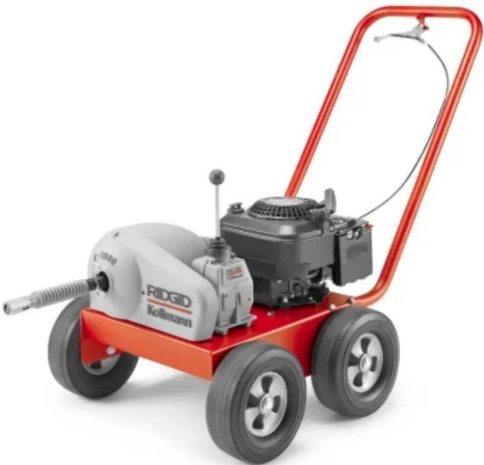
Download the instructions for your Machine tool in PDF format for free! Find your manual K-1000 - RIDGID and take your electronic device back in hand. On this page are published all the documents necessary for the use of your device. K-1000 by RIDGID.
USER MANUAL K-1000 RIDGID
Read this Operator's Manual carefully before using this tool. Failure to understand and follow the contents of this manual may result in carbon monoxide poisoning, fire and/or serious personal injury.
Rodder
natural_image
Red and white photo of a red-handled industrial water heater with a propeller and fan (no visible text or symbols)RIDGID®
Table of Contents
Recording Form for Machine Model and Serial Number....1
General Safety Information
Work Area Safety 2
Personal Safety 2
Tool Use and Care 2
Service 2
Specific Safety Information
Machine Safety....2
Description, Specifications and Standard Equipment
Description ....3
Specifications ....3
Standard Equipment....3
Rods and Tools 4
Machine Assembly
Instructions for Installing Handle and Throttle Cable....4
Instructions for Engine....4
Instructions for Assembling Rods and Tools....4
Machine Inspection ....5
Machine and Work Area Set Up ....5
Operation Instructions
Operating Rodder....6
Accessories 7
Maintenance Instructions
Torque Limiter Adjustment 8
Torque Limiter Adjustment Using Torque Wrench 8
Torque Limiter Adjustment Using Spring Scale....9
Engine 9
Transmission....9
Centrifugal Clutch....9
Wheel Assemblies....9
Checking Engine Idle (RPM) Speed....9
Throttle Adjustment....9
“V” Belt Tension Adjustment....9
Main Bearings ....10
Storing of Rods....10
Tool Storage....10
Service and Repair ....10
Lifetime Warranty....Back Cover
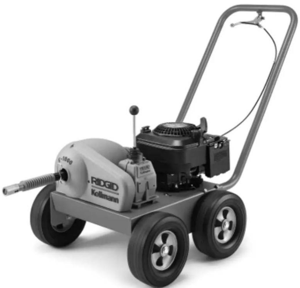
K-1000 Rodder
natural_image
Ridgeid Kollmann electric water heater with attached propeller and wheels (no visible text or symbols)| K-1000 Rodder | |
| Record Serial Number below and retain product serial number which is located on nameplate. | |
| Serial No. | |
General Safety Information
WARNING! Read and understand all instructions. Failure to follow all instructions listed below may result in fire and/or serious personal injury.
SAVE THESE INSTRUCTIONS!
Work Area Safety
- Keep your work area clean and well lit. Cluttered benches and dark areas invite accidents.
- Do not operate power tools in explosive atmospheres, such as in the presence of flammable liquids, gases, or dust. Tools create sparks which may ignite the dust or fumes.
- Keep bystanders, children, and visitors away while operating a tool. Distractions can cause you to lose control.
- Keep the engine at least one meter (3 feet) away from buildings and other equipment during operation. Do not place flammable objects close to engine. Procedures should be followed to prevent fire hazards and to provide adequate ventilation.
Personal Safety
- Stay alert, watch what you are doing and use common sense when operating a power tool. Do not use tool while tired or under the influence of drugs, alcohol, or medications. A moment of inattention while operating power tools may result in serious personal injury.
- Dress properly. Do not wear loose clothing or jewelry. Contain long hair. Keep your hair, clothing, and gloves away from moving parts. Loose clothes, jewelry, or long hair can be caught in moving parts.
- Remove adjusting keys before turning the tool ON. A wrench or a key that is left attached to a rotating part of the tool may result in personal injury.
- Do not over-reach. Keep proper footing and balance at all times. Proper footing and balance enables better control of the tool in unexpected situations.
- Use safety equipment. Always wear eye protection. Dust mask, non-skid safety shoes, hard hat, or hearing protection must be used for appropriate conditions.
Tool Use and Care
- Do not force tool. Use the correct tool for your application. The correct tool will do the job better and safer at the rate for which it is designed.
- Store idle tools out of the reach of children and
other untrained persons. Tools are dangerous in the hands of untrained users.
- Maintain tools with care. Keep cutting tools sharp and clean. Properly maintained tools with sharp cutting edges are less likely to bind and are easier to control.
- Check for misalignment or binding of moving parts, breakage of parts, and any other condition that may affect the tools operation. If damaged, have the tool serviced before using. Many accidents are caused by poorly maintained tools.
- Use only accessories that are recommended by the manufacturer for your tool. Accessories that may be suitable for one tool may become hazardous when used on another tool.
- Keep handles dry and clean; free from oil and grease. Allows for better control of the tool.
Service
- Tool service must be performed only by qualified repair personnel. Service or maintenance performed by unqualified repair personnel could result in injury.
- When servicing a tool, use only identical replacement parts. Follow instructions in the Maintenance Section of this manual. Use of unauthorized parts or failure to follow maintenance instructions may create a risk of injury.
Specific Safety Information
WARNING
Read this operator's manual carefully before using the RIDGID K-1000 Rodder. Failure to understand and follow the contents of this manual may result in fire and/or serious personal injury.
Call the Ridge Tool Company, Technical Service Department at (800) 519-3456 if you have any questions.
Machine Safety
- Wear leather gloves provided with the machine. Never grasp a rotating rod with a rag or loose fitting cloth glove. Could become wrapped around the rod and cause serious injury.
- Wear safety glasses and rubber soled, non-slip shoes. Use of this safety equipment may prevent serious injury.
- Never operate machine with guards removed. Fingers can be caught between the chain sprocket.
- Do not operate machine in (REV) reverse. Operating
machine in reverse can result in rod damage and is used only to back tool out of an obstruction.
- Start engine with shift lever in NEUTRAL position. Shift lever must also be in NEUTRAL (straight up) position when adding or removing tools and rod or any other time when machine is not in use. Prevents unexpected rotation of rods.
- Disconnect spark plug when performing maintenance on Rodder or engine. This action will prevent accidental starting and serious injury.
- Operate rodder properly. Do not operate with more than 20 feet of rod between machine and manhole. The arcing of rod at manhole should not exceed 3 feet. This will minimize the possibility of kinking rods and serious injury.
- When striking an obstacle that causes the tool to hang-up, do not attempt to force the machine by manually pushing on the exposed rods. Do not uncouple rods that are in a stressed condition. This will cause kinking and whipping of the rods which could cause serious injury.
- Do not overstress rods. Do not use badly worn or bent rods. Be sure torque limiter is adjusted properly to 50 ft.-lbs. maximum. Overstressing rods because of obstruction can be dangerous to operators as rods may twist or kink.
- Use caution when handling gasoline. Refuel in well-ventilated area. Do not overfill fuel tank and do not spill fuel. Make sure tank cap is closed properly. Gasoline is extremely flammable and is explosive under certain conditions.
- Never run the engine in an enclosed or confined area. Exhaust contains poisonous carbon monoxide gas; exposure may cause loss of consciousness and may lead to death. Exhaust also contains chemicals that the State of California believes may cause cancer or reproductive harm.
- Be careful not to touch the muffler while it is hot. To avoid severe burns or fire hazards, let the engine cool before transporting or storing it indoors. The muffler becomes very hot during operation and remains hot for a while after stopping the engine.
- Only use the K-1000 to clean straight drain lines 8" to 24" in diameter. Follow instructions on the use of the machine. Other uses or modifying the rodder for other applications may increase the risk of injury.
- Do not use tool if releasing the throttle does not stop the rod rotation. Any tool that cannot be controlled is dangerous and must be repaired.
Description, Specifications and Standard Equipment
Description
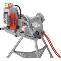
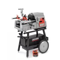
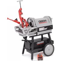
The RIDGID Model K-1000 Rodder is a gasoline, engine-driven machine for cleaning straight line work in sewer mains, drain tile, water mains and process piping. Will clean drains 8" to 24" in diameter and 500 feet in length. The machine uses sectional solid rods that have a quick coupler for connecting or disconnecting tools and rods.
Specifications
Line Capacity....8" – 24" dia. Drain/Sewer Line
Transmission (2 speed):
FWD Gear......133 RPM
REV Gear......133 RPM
Throttle ....Variable speed, returns speed to idle when operator releases grip
Engine ....4 cycle, gasoline, 6hp Vertical shaft
Clutch ....Centrifugal clutch open when operator releases throttle
Length 32"
Width 26"
Height (assembled
with handle ....40"
Weight
Machine only ....160 lbs.
Standard Equipment
| Catalog No. | Model Description |
| 59175 K | 1000 Rodder Machine, includes:– B-3542 Rod Driver– A-2704 Tool Driver– A-3567 Drive Pin– R-0 Rod Turner– A-4558 Torque Adapter– A-12 Coupling Pin Key– A-1 Operator’s Mitt (LH)– A-2 Operator’s Mitt (RH) |
| 84295 K | 1000 Rodder Machine, same as above, plus:– 20 Sections of A-2475, ^3/16 ” Rod,Total of 100 Feet– T-300 Spear Head Cutter– T-317 Auger– T-326 Pick-Up Tool |
Rods
| Catalog No. | Model No. | Description |
| 60355 | A-2474 3' | Solid Sectional Rod, includes R-1 Male and R-2 Female Couplings |
| 60360 | A-2475 5' | Solid Sectional Rod, includes R-1 Male and R-2 Female Couplings |
| 60365 | A-2476 10' | Solid Sectional Rod, includes R-1 Male and R-2 Female Couplings |
Tools and Replacement Blades
| Catalog No. | Model Description | |
| 62045 T-300 Spear Head | ||
| 62050 T-301 Round Stock Corkscrew, 1 | 12" | |
| 62055 T-302 Round Stock Corkscrew, 2" | ||
| 62060 T-303 Round Stock Corkscrew, 2 | 12" | |
| 62065 T-304 Round Stock Corkscrew, 3" | ||
| 62070 T-305 Round Stock Corkscrew, 3 | 12" | |
| 62075 T-306 Double Corkscrew, 3" | ||
| 62080 T-307 Double Corkscrew, 4" | ||
| 62085 T-308 Double Corkscrew, 5" | ||
| 62090 T-309 Square Stock Corkscrew, 3" | ||
| 62095 T-310 Square Stock Corkscrew, 4" | ||
| 62100 T-311 Square Stock Corkscrew, 5" | ||
| 62105 T-312 Square Stock Corkscrew, 6" | ||
| 62370 T-313 Square Stock Corkscrew, 8" | ||
| 62375 T-314 Square Stock Corkscrew, 10" | ||
| 62380 T-315 Square Stock Corkscrew, 12" | ||
| 62110 T-316 Auger, 3" | ||
| 62115 T-317 Auger, 4" | ||
| 62120 T-318 Auger, 5" | ||
| 62125 T-319 Auger, 6" | ||
| 62385 T-320 Auger, 8" | ||
| 62390 T-321 Auger, 10" | ||
| 62140 T-326 Pick-Up Tool | ||
The following Heavy-duty Cable Tools are also recommended for use with rod.
| Catalog No. No. Description Blade(s) | |||
| 61800 T-2 | Heavy-Duty Straight Auger | — | |
| 61790 T-4 | Heavy-Duty Funnel Auger | — | |
| 63200 T-7 | Hook Auger | — | |
| 61960 | T-16 | Spiral Bar Cutter, 4" | 97855 |
| 61850 | T-17 | Spiral Bar Cutter, 6" | 97955 |
| 61855 | T-18 | Spiral Bar Cutter, 8" | 97960 |
| 63085 | T-23 | Spiral Sawtooth Cutter, 4" | 97850 |
| 59765 | T-24 | 4-Blade Cutter, 2 12 " | 97940 |
| 59770 | T-25 | 4-Blade Cutter, 3 12 " | 97975 |
| 59775 | T-26 | 4-Blade Cutter, 4 12 " | 97805 |
| 59780 | T-26A | 4-Blade Cutter, 5 12 " | 97980 |
Machine Assembly
WARNING
To prevent serious injury, proper assembly of the K-1000 Rodder is required. The following procedures should be followed:
Instructions for Installing Handle and Throttle Cable
- Insert handle assembly into handle openings in base and attach by means of four 38 " bolts provided (Figure 1).
- Attach free end of throttle cable to throttle handle and secure cable to left side of handle with two cable clamps provided.
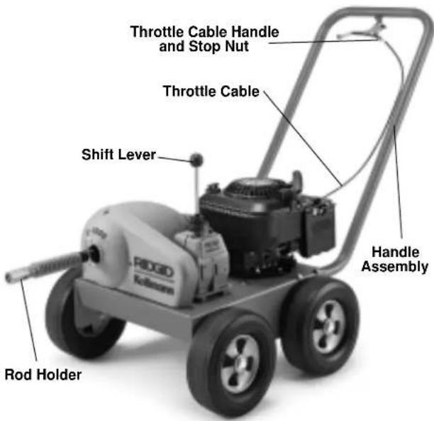
Figure 1
Instructions for Engine
- Engine is shipped without oil. Fill with oil prior to starting engine (See enclosed Engine Owner's Manual for details).
CAUTION Failure to fill engine with oil will result in engine failure.
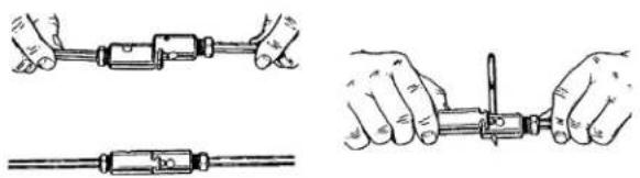
Instructions for Assembling Rods and Tools
- To connect rods, align and snap the couplings together for a solid connection (Figure 2).
natural_image
Illustration of hands using a tool to adjust a mechanical component (no text or symbols present)Figure 2 – Connecting/Disconnecting Rods
- To disconnect, insert pin key and slide couplings apart.
Machine Inspection
WARNING

natural_image
Silhouette of a person with smoke or vapor spout emitting plumes (no text or symbols)
natural_image
Silhouette of a hand holding a rope with a small loop (no text or symbols)To prevent serious injury, inspect your Rodder. The following inspection procedures should be performed on a daily basis:
- Check engine crankcase oil level. If low, add oil (see enclosed Engine Owner's Manual for details).
- Check engine fuel level. If low, add unleaded gasoline with a pump octane rating of 86 or higher. (See enclosed Engine Owner's Manual for details).
⚠ WARNING Use caution when handling gasoline. Refuel in well-ventilated area. Do not over fill fuel tank and do not spill fuel. Make sure tank cap is closed properly.
- Inspect the rodder for any broken, missing, mis-aligned or binding parts as well as any other conditions which may affect the safe and normal operation of the machine. If any of these conditions are present, do not use the Rodder until any problem has been repaired.
- Lubricate the Rodder, if necessary, according to the Maintenance Instructions.
-
Use tools and accessories that are designed for your rodder and meet the needs of your application. The correct tools and accessories will allow you to do the job successfully and safely. Accessories suitable for use with other equipment may be hazardous when used with this rodder.
-
Clean any oil, grease or dirt from all equipment handles and controls. This reduces the risk of injury due to a tool or control slipping from your grip.
- Inspect the cutting edges of your tools. If necessary, have them sharpened or replaced prior to using the Rodder. Dull or damaged cutting tools can lead to binding and rod kinking.
- Inspect rod and couplings for wear and damage. Rods should be replaced when they become severely worn, corroded or bent.
⚠ WARNING Worn or damaged rods can break causing serious injury.
- Depending on use, torque limiter should be checked every month. The purpose of the torque limiter is to minimize kinking of the rods because of excessive torque caused by heavy blockage within pipe. Torque limiter must be adjusted to a maximum of 50 ft.-lbs. (600 in.-lbs.). Refer to Adjustment Procedure in Maintenance Section.
⚠ WARNING Improperly adjusted torque limiter can result in kinking of the rods and serious injury.
Machine and Work Area Set-Up
WARNING


To prevent serious injury, proper set-up of the machine and work area is required. The following procedures should be following to set-up the machine.
-
Check work area for:
-
Adequate lighting.
- Flammable liquids, vapors or dust that may ignite.
- Adequate ventilation for engine exhaust.
⚠ WARNING Exhaust contains poisonous carbon monoxide gas. Exposure may cause loss of consciousness and may lead to death.
- Place machine 20 feet from manhole. Greater distance can result in kinking and whipping of rods.
-
Transmission shift lever should be in NEUTRAL (straight up) position.
-
Select and install proper tool/cutter to end of rod. To connect, snap the male and female couplings together. To disconnect, insert pin key and slip apart (Figure 2).
- Couple enough rod together to reach down into main and extend out no more than 20 feet.
Operating Instructions
WARNING

Rods may whip or kink. Fingers, hands or other body parts can be crushed or broken. Carbon monoxide poisoning can occur if operated in a confined area.
Wear gloves provided with machine. Never grasp a rotating rod with a rag or loose fitting cloth glove that may become wrapped around the rod causing serious injury.
Always wear eye protection to protect your eyes against dirt and other foreign objects. Wear rubber soled, non-slip shoes.
⚠ WARNING Always follow the correct operating procedure in order to maintain proper control of the machine and rods and prevent serious injury (Figure 3).
- When working through a manhole, 2 persons are required. Machine operator and rod handler at manhole.
- Do not operate with more than 20 feet of rod between machine and manhole.
- Arcing of the rod at manhole should not exceed 3 feet.
- If kinking occurs, move all people to rear of machine before shifting transmission. Violent whipping action of rods could cause serious injury.
- If tool hangs up in obstacle, do not force the machine by manually pushing in the exposed rods.
Operating Rodder
- Transmission shift lever should be in NEUTRAL (straight up) position.
- Set choke control handle to CHOKE and turn engine over a few times with pull starter.
- When engine catches, set at RUN and pull throttle control to desired speed.
NOTE! Squeeze throttle handle to REV engine at high speed and immediately release so that engine returns to idle.
⚠ WARNING At idle speed, the drive shaft should not be turning. If drive shaft does turn, make sure that throttle control spring is connected or adjust idle speed at the throttle cable handle by loosening stop nut and adjusting cable length (Figure 1).
- Position rod assembly at manhole.
- Holding onto both ends of a piece of rope, lower auger or probing tool into manhole, guiding tool towards lateral opening.
- Use a hand-operated rod turner and feed rod a short distance into lateral opening.
- Release one end of rope and remove from manhole.
- Couple rod to machine to rod holder (Figure 1).
⚠ WARNING Make certain that rod handler is wearing standard equipment leather mittens with riveted palms. Use no substitute.
-
Place transmission shift lever in FWD gear.
-
Squeeze throttle handle for desired rod (RPM) rotation and push machine forward.
-
As machine is pushed forward, the rod handler should push downward on rod with rod guided between thumbs and palms of hands with fingers extended (Figure 3).
WARNING
The arcing of rod at manhole should not exceed 3 feet.
-
When machine is approximately 8 feet from manhole, release throttle handle and place transmission shift lever in NEUTRAL (straight up) position.
-
Uncouple rod from rod holder, move machine back approximately 10 feet and connect additional rods.
⚠ WARNING Do not uncouple rod in stressed conditions.
- Continue feeding rod by following steps 9 through 13 until through an obstruction.
⚠ WARNING When striking an obstacle that causes tool to hang-up, do not attempt to force the machine by manually pushing on the exposed rods. This will cause kinking and whipping of the rods.
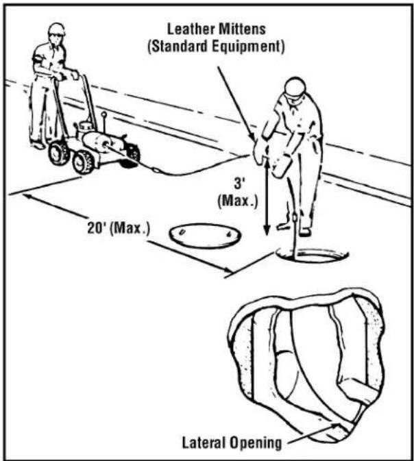
Figure 3 – Operating Rodder
- If tool gets hung up in obstruction, release throttle handle. Put machine in reverse gear, squeeze throttle control and pull machine back to release tool.
⚠ WARNING Only operate machine in reverse to back tool out of obstruction.
WARNING
If kinking of rod occurs, move all people to rear of machine before shifting transmission. Violent whipping action of rod could cause serious injury.
-
If rod kinking occurs, release throttle to return engine to idle speed. Be sure all personnel are to the rear of the machine. Back the machine to remove all slack from the rods. Shift transmission to neutral to insure all torque is released.
-
Proceed through obstruction with transmission shift lever in FWD gear.
-
After clearing obstruction continue through line to make sure that it is clear.
-
When completed, leave transmission shift lever in FWD gear and back machine away from sewer opening.
-
With approximately 20 feet of rods are removed from the manhole, place transmission shift lever in neutral (straight up) position.
-
Uncouple rod from rod holder and disconnect rods by inserting pin key and sliding coupling apart (Figure 2).
⚠ WARNING Do not uncouple rod in stressed condition.
-
Move machine to manhole and connect rod to rod holder. Place machine in FWD gear and follow steps 19 through 21 until all the rods have been removed from the main.
-
Move choke control handle to STOP position to shift off engine.
Accessories
⚠ WARNING Only the following RIDGID products have been designed to function with the K-1000 Rodder. Other accessories suitable for use with other tools may become hazardous when used on the K-1000. To prevent serious injury, use only the accessories listed below.
| Catalog No. No. Description | |
| 59835 K-10 Complete Set of Quick-Connect Rod Couplings: One Each R-1 and R-2 | |
| 59560 R-1 Male Rod Coupling59555 R-2 Female Rod Coupling | |
| 61875 R-7 Male Tool Coupling, connectsTool Adapter to Rodding Tool61885 R-8 Female Tool Coupling, connectsTool to Tool Adapter | |
| 60700 A-2704 Tool Adapter, includes R-2 and R-7 Couplings | |
| 62170 B-3542 Rod Holder For K-100061895 — Rod Driver for K-2000 | |
| 62815 R-O Rod Turner, used to manually turn Rods in short runs | |
| 59205 A-1 Left-Hand Mitt59295 A-2 Right-Hand Mitt | |
| 59360 A-3 Tool Box | |
| 59225 A-12 Coupling Pin Key |
Maintenance Instructions
WARNING
Disconnect spark plug when performing maintenance on rodder or engine.
Torque Limiter
(Figures 4 & 5)
The purpose of the torque limiter is to minimize kinking of rods and excessive torque through the transmission system. Kinking is caused by heavy blockage within pipe and must be adjusted to no more than 50 ft.-lbs. (600 inch-lbs.).
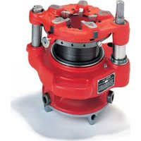
The torque limiter consists of two fiber discs with one assembled on either side of the drive sprocket A-3569. When clamped against sprocket, the torque limiter produces the only connection between drive shaft B-3548 and drive sprocket A-3569.
Torque Limiter Adjustment Using Torque Wrench
(Figures 4 & 5)
- Disconnect spark plug wire.
- Remove 3 screws and guard to expose torque limiter.
-
Back off three cap screws so they do not contact backup plate. They are now free to be turned by hand.
-
Back off torque limiter threaded ring until it turns freely. Hand-tighten torque limiter threaded ring against backup plate.
- Hand-tighten three cap screws to make contact with backup plate.
NOTE! This insures that all three screws provide even pressure against backup late at beginning of torque adjustment. - Insert a ^3/_16 " hex key or pin through both sides of chain near drive sprocket to lock chain.
- Insert torque testing tool into shaft B-3548 and lock in place with drive pin.
- Install a 1 inch socket on torque wrench and apply torque to torque testing tool. Record torque reading at which torque limiter slips.
- If torque reading is less than 50 ft.-lbs. tighten the 3 cap screws uniformly and recheck torque reading. If torque reading is greater than 50 ft.-lbs. loosen the 3 cap screws uniformly and recheck torque reading.
NOTE! Turn cap screws 14 turn for initial adjustment. Reduce to 18 turn or less for final adjustment to obtain 50 ft.-lbs. reading.
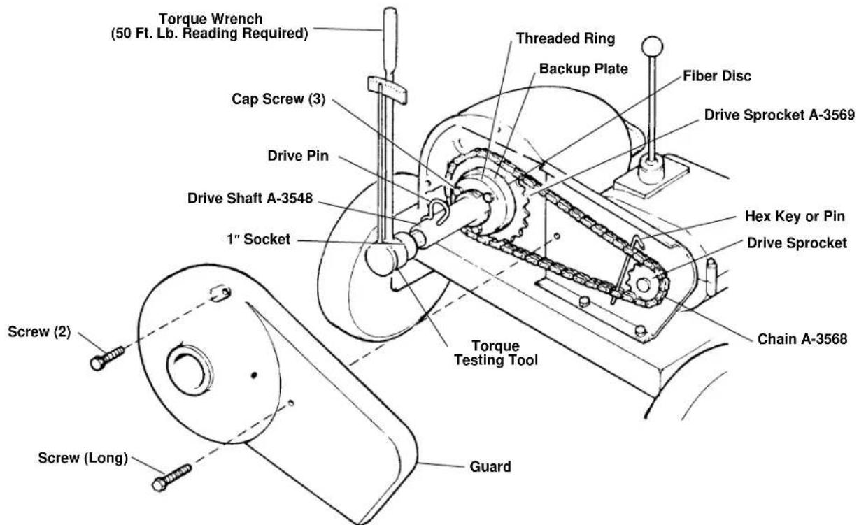
Figure 4 – Adjusting Torque Limiter
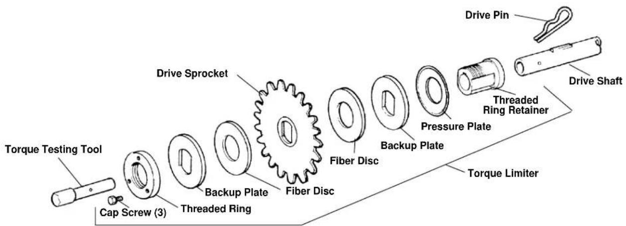
Figure 5 – Torque Limiter, Torque Testing Tool, Drive Sprocket and Drive Shaft
- Remove hex key or pin that was installed to secure chain.
- Remove torque wrench, drive pin and torque testing tool.
- Install guard and secure with 3 screws. One screw is longer than others and is used in lower right hand side.
- Connect spark plug.
Torque Limiter Adjustment Using Spring Scale
- Follow steps 1 through 7 of Torque Limiter Adjustment using Torque Wrench.
- Snap socket drive handle into a 1 inch socket and install on torque testing tool.
- Measure 12 inches from center of socket along socket drive handle and attach spring scale.
- Pull on spring scale until torque limiter slips. Scale should read 50lbs.
- Repeat step 9 above until 50 lbs. reading is obtained.
Engine
Always check engine oil level. For complete directions on engine maintenance, consult the Engine manual enclosed.
Transmission
The transmission needs no relubrication, however, a leak in a seal could allow grease to be depleted after several hours. Such a leak will be obvious and should be corrected.
Centrifugal Clutch
Centrifugal clutch will automatically engage when the throttle is opened. No maintenance should be necessary. However, if slippage should occur from dirt or grease entering clutch, the foreign material should be removed.
Wheel Assemblies
All four wheel assemblies should be greased once a year. The grease fitting is located on the inside face of the hub.
Checking Engine Idle (RPM) Speed
After engine has started, squeeze throttle handle to REV engine at high speed and immediately release so that engine returns to idle.
▲WARNING At idle speed the drive shaft should not be turning. If drive shaft does turn, make sure that Throttle Control Spring is connected or adjust idle speed at the throttle cable handle by loosening stop nut and adjusting cable length (Figure 1).
Throttle Adjustment
Throttle control is factory set and should not require adjustment. If idle speed seems too high or engine does not speed up when throttle is pulled check throttle linkage.
- Check speed adjustment by adjusting cable position; loosen clamp at bracket and move slightly.
- For idle adjustment and mixture control, refer to engine manual enclosed.
"V" Belt Tension Adjustment
"V" Belt should be checked at least once a month. Belt tension should be just enough to drive maximum load at
high speed with throttle open. Excess belt tension will cause the centrifugal clutch to creep at idle speed. "V" Belt is tightened by loosening engine mounting bolts and sliding engine to rear.
Main Bearings
The Main Bearings should be greased after using machine on 12 jobs or once every three months, whichever comes first. Guard must be removed to grease front main bearing. Chain should be checked and greased while guard is removed.
⚠ WARNING Do not use machine with guard removed.
Storing of Rods
Rods should be thoroughly flushed with water to prevent damaging effect of some drain cleaning compounds. Periodically, lubricate rods and couplings with oil. When storing, uncouple rods. Do not store in a coil since this could cause bending and damage.
Tool Storage
⚠ WARNING Motor-driven equipment must be indoors or well covered in rainy weather. Store the machine in a locked area that is out of reach of children and people unfamiliar with machine. This machine can cause serious injury in the hands of untrained users.
Service and Repair
WARNING
The “Maintenance Instructions” will take care of most of the service needs of this machine. Any problems not addressed by this section should only be handled by an authorized RIDGID service technician.
Machine should be taken to a RIDGID Independent Authorized Service Center or returned to the factory. All repairs made by Ridge service facilities are warranted against defects in material and workmanship.
⚠ WARNING When servicing this machine, only identical replacement parts should be used. Failure to follow these instructions may create a risk of serious injury.
If you have any questions regarding the service or repair of this machine, call or write to:
Ridge Tool Company
Technical Service Department
400 Clark Street
Elyria, Ohio 44035-6001
Tel: (800) 519-3456
E-mail: TechServices@ridgid.com
For name and address of your nearest Independent Authorized Service Center, contact the Ridge Tool Company at (800) 519-3456 or http://www.ridgid.com
natural_image
Ridgei Kollmann electric water heater with attached pump and wheels (no visible text or symbols)CONSERVEZ CES INSTRUCTIONS!
natural_image
Illustration of hands using a tool to adjust or install a mechanical component (no text or symbols present)natural_image
Silhouette of a person with smoke or vapor spout emitting from a flame (no text or symbols)
natural_image
Silhouette of a hand holding a circular object with a chain, no text or symbols presentTechnical Service Department
400 Clark Street
Elyria, Ohio 44035-6001
Tel: (800) 519-3456
E-mail: TechServices@ridgid.com
? This item seems to relate more specifically to electrical equipment, which this machine is not. Please advise.
Limpiadora a varillas K-1000

natural_image
Ridgid Kollmann electric water heater with attached pump and wheels (no visible text or symbols)(FORWARD)....133 RPM
Marcha atrás o reversa
(REVERSE)....133 RPM
natural_image
Illustration of hands using a tool to adjust or install a cable, showing three different configurations (no text or symbols present)natural_image
Silhouette of a person blowing bubbles with smoke (no text or symbols)
natural_image
Silhouette of a hand holding a rope with a small object inside (no text or symbols)Technical Service Department
400 Clark Street
Elyria, Ohio 44035-6001
Tel: (800) 519-3456
E-mail: TechServices@ridgid.com
RIDGID® tools are warranted to be free of defects in workmanship and material.
How long coverage lasts
This warranty lasts for the lifetime of the RIDGID® tool. Warranty coverage ends when the product becomes unusable for reasons other than defects in workmanship or material.
How you can get service
To obtain the benefit of this warranty, deliver via prepaid transportation the complete product to RIDGE TOOL COMPANY, Elyria. Ohio. or any authorized RIDGID® INDEPENDENT SERVICE CENTER. Pipe wrenches and other hand tools should be returned to the place of purchase.
What we will do to correct problems
Warranted products will be repaired or replaced, at RIDGE TOOL'S option, and returned at no charge; or, if after three attempts to repair or replace during the warranty period the product is still defective, you can elect to receive a full refund of your purchase price.
What is not covered
Failures due to misuse, abuse or normal wear and tear are not covered by this warranty. RIDGE TOOL shall not be responsible for any incidental or consequential damages.
How local law relates to the warranty
Some states do not allow the exclusion or limitation of incidental or consequential damages, so the above limitation or exclusion may not apply to you. This warranty gives you specific rights, and you may also have other rights, which vary, from state to state, province to province, or country to country.
No other express warranty applies
This FULL LIFETIME WARRANTY is the sole and exclusive warranty for RIDGID ^® products. No employee, agent, dealer, or other person is authorized to alter this warranty or make any other warranty on behalf of the RIDGE TOOL COMPANY.

Ce qui est couvert
Elyria, Ohio 44035-6001