916 - Drill RIDGID - Free user manual and instructions
Find the device manual for free 916 RIDGID in PDF.

| Product Type | Roll Groover |
| Brand | RIDGID |
| Model | 916 |
| Grooving Capacity (Schedule 10 Steel) | 1¼ to 6 in diameter |
| Grooving Capacity (Schedule 40 Steel) | 1¼ to 3 in diameter |
| Grooving Capacity (Copper Types K, L, M, DWV) | 2 to 6 in diameter |
| Weight | 33 lb (15.0 kg) |
| Compatible Drive Systems | RIDGID No. 300, 300 Compact, 535, 535A, 1822-I |
| Maximum Rotational Speed | 58 rpm |
| Depth Adjustment | Adjustment screw with integral single-turn handle mechanism |
| Standard Equipment | Groove roll 1¼-6 in, drive roll 1¼-6 in, tubular feed lever, drive adapter (if needed) |
| Groovable Materials | Carbon steel, stainless steel, aluminum, copper |
| Power Supply | Via electric drive system (grounded outlet required) |
| Maintenance | Lubricate bearings after roll change; store dry |
| Safety | Use with foot pedal; wear safety glasses; keep hands away from rolls; do not wear loose clothing |
| Optional Accessories | Roll sets for copper, AWWA, 1 in; adapter for 300 Compact; diameter tapes |
| Warranty | Lifetime warranty (tool lifetime) |
Frequently Asked Questions - 916 RIDGID
User questions about 916 RIDGID
0 question about this device. Answer the ones you know or ask your own.
Ask a new question about this device
Download the instructions for your Drill in PDF format for free! Find your manual 916 - RIDGID and take your electronic device back in hand. On this page are published all the documents necessary for the use of your device. 916 by RIDGID.
USER MANUAL 916 RIDGID
Read this Operator's Manual carefully before using this tool. Failure to understand and follow the contents of this manual may result in electrical shock, fire and/or serious personal injury.
Portable Roll Groover
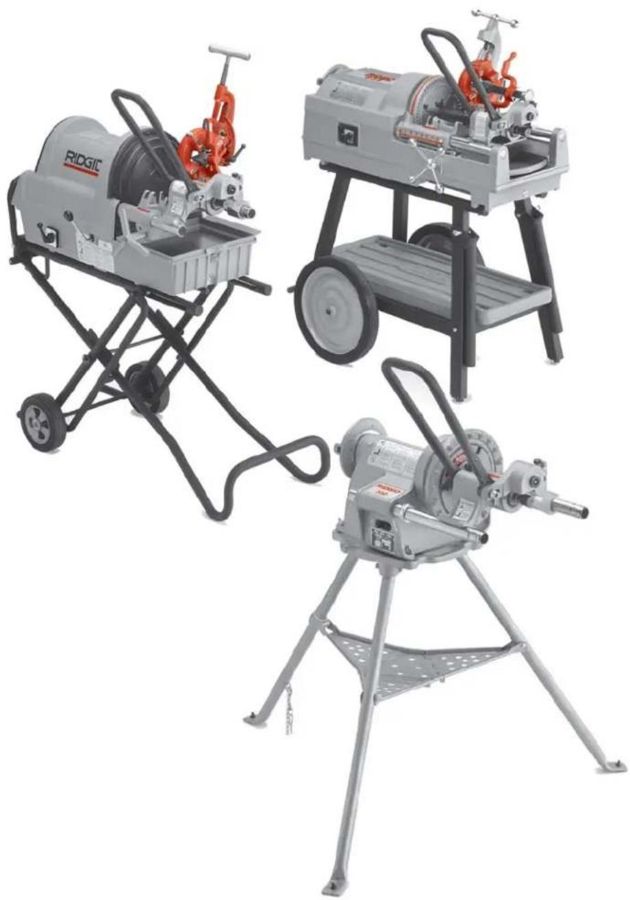
natural_image
Three industrial printing machines with different designs and colors, displayed against a plain background (no visible text or labels)RIDGID®
Table of Contents
General Safety Information
Work Area Safety....2
Electrical Safety 2
Personal Safety 2
Tool Use and Care....3
Service....3
Specific Safety Information
Foot Switch Safety 3
Roll Groover Safety 3
Description, Specifications, Standard Equipment
Description 4
Specifications....4
Standard Equipment 4
916 Roll Groover Models 4
Roll Groover Assembly Instructions
Installing 916 Roll Groover on 300 Power Drive ....4
Installing Drive Bar Adapter For 1822-1, 535 or 300 Compact Threading Machines ....5
Installing 916 Roll Groover on 535A, 535M, 1822-I or 300 Compact Threading Machines
Mounted on 100, 150 or 200 Stands ....5
Installing 916 Roll Groover on 1822-I Threading Machine Mounted on 1406 Stand ....5
Installing 916 Roll Groover on 300 Compact Threading Machine with 250 Stand....6
Machine Inspection
Machine and Work Area Set-Up 7
Operating the 916 Roll Groover
Pipe Preparation 8
Pipe/Tubing Length 8
Pipe Set-Up 8
Adjusting Roll Groove Depth 9
Forming the Roll Groove ....10
Roll Grooving Tips with 916....10
Grooving Short Lengths of Pipe....11
Removing and Installing
Removing and Installing Groove Roll....11
Removing and Installing Drive Roll 12
Roll Grooving Copper with No. 916
Tube Preparation 12
Forming Roll Groove ....12
Roll Grooving Smaller Diameter Steel Pipe....12
Accessories 12
Maintenance Instructions
Lubrication 13
Machine Storage ....13
Service and Repair....13
Table I Standard Roll Groove Specification....14
Table II Pipe Maximum and Minimum Wall Thickness ....14
Table III Troubleshooting....15
Table IV Copper Roll Groove Specifications 16
Lifetime Warranty ....Back Cover
916 Roll Groover
For Models No. 300PD, 300 Compact, 535 or 1822-I Threading Machine
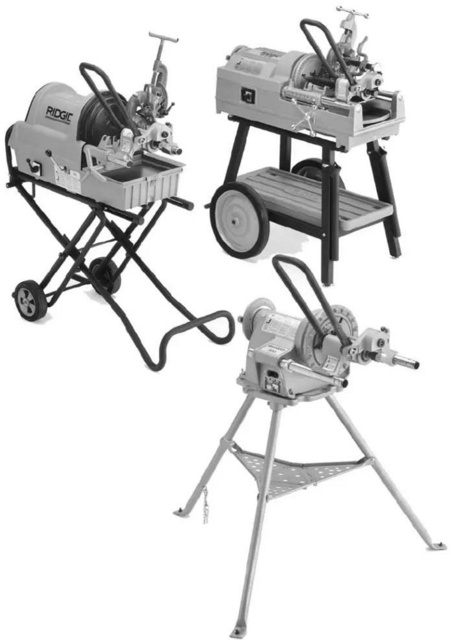
natural_image
Three industrial printing machines with different mechanical designs and colors, displayed against a plain background (no visible text or labels)General Safety Information
WARNING! Read and understand all instructions. Failure to follow all instructions listed below may result in electric shock, fire, and/or serious personal injury.
SAVE THESE INSTRUCTIONS!
Work Area Safety
- Keep your work area clean and well lit. Cluttered benches and dark areas invite accidents.
- Do not operate power tools in explosive atmospheres, such as in the presence of flam mable liquids, gases, or dust. Electric motors create sparks which may ignite the dust or fumes.
- Keep by-standers, children, and visitors away while operating a tool. Distractions can cause you to lose control.
- Keep floors dry and free of slippery materials such as oil. Slippery floors invite accidents.
Electrical Safety
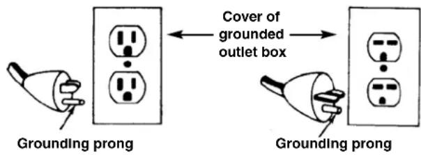
- Grounded tools must be plugged into an outlet, properly installed and grounded in accordance with all codes and ordinances. Never remove the grounding prong or modify the plug in any way. Do not use any adapter plugs. Check with a qualified electrician if you are in doubt as to whether the outlet is properly grounded. If the tools should electrically malfunction or break down, grounding provides a low resistance path to carry electricity away from the user.
- Avoid body contact with grounded surfaces. There is an increased risk of electrical shock if your body is grounded.
- Do not expose electrical tools to rain or wet conditions. Water entering a tool will increase the risk of electrical shock.
-
Do not abuse cord. Never use the cord to pull the plug from an outlet. Keep cord away from heat, oil, sharp edges or moving parts. Replace damaged cords immediately. Damaged cords increase the risk of electrical shock.
-
When operating a tool outside, use an outdoor extension cord marked "W-A" or "W". These cords are rated for outdoor use and reduce the risk of electrical shock.
- Keep all extension cord connections dry and off the ground. Do not touch plugs with wet hands. This practice reduces the risk of electrical shock.
- Use only three-wire extension cords which have three-prong grounding plugs and three-pole receptacles which accept the tool's plug. Use of other extension cords will not ground the tool and increase the risk of electrical shock.
- Use proper extension cords. (See chart.) Insufficient conductor size will cause excessive voltage drop and loss of power.
| Minimum Wire Gauge for Extension Cord | |||
| Nameplate Amps | Total Length (in feet) | ||
| 0 – 25 26 | -50 51 – 100 | ||
| 0 – 6 18 | AWG 16 AWG | 16 AWG | |
| 6 – 10 18 | AWG 16 AWG | 14 AWG | |
| 10 – 12 16 | AWG 16 AWG | 14 AWG | |
| 12 – 16 14 | AWG 12 AWG | NOT RECOMMENDED | |
Personal Safety
- Stay alert, watch what you are doing and use common sense when operating a tool. Do not use tools while tired or under the influence of drugs, alcohol, or medications. A moment of inattention while operating power tools may result in serious personal injury.
- Dress properly. Do not wear loose clothing or jewelry. Contain long hair. Keep your hair, clothing, and gloves away from moving parts. Loose clothes, jewelry, or long hair can be caught in moving parts.
- Avoid accidental starting. Be sure switch is OFF before plugging in. Plugging in tools that have the switch ON invites accidents.
- Remove wrenches or adjusting keys before turning the tool ON. A wrench or a key that is left attached to a rotating part of the tool may result in personal injury.
- Do not over-reach. Keep proper footing and balance at all times. Proper footing and balance enables better control of the tool in unexpected situations.
- Use safety equipment. Always wear eye protection. Dust mask, non-skid safety shoes, hard hat, or hearing protection must be used for appropriate conditions.
Tool Use and Care
- Do not use tool if switch does not turn it ON or OFF. Any tool that cannot be controlled with the switch is dangerous and must be repaired.
- Disconnect the plug from the power source before making any adjustments, changing accessories, or storing the tool. Such preventive safety measures reduce the risk of starting the tool accidentally.
- Store idle tools out of the reach of children and other untrained persons. Tools are dangerous in the hands of untrained users.
- Check for misalignment or binding of moving parts, breakage of parts, and any other condition that may affect the tools operation. If damaged, have the tool serviced before using. Many accidents are caused by poorly maintained tools.
- Use only accessories that are recommended by the manufacturer for your model. Accessories that may be suitable for one tool may become hazardous when used on another tool.
- Keep handles dry and clean; free from oil and grease. Allows for better control of the tool.
Service
- Tool service must be performed only by qualified repair personnel. Service or maintenance performed by unqualified repair personnel could result in injury.
- When servicing a tool, use only identical replacement parts. Follow instructions in the Maintenance Section of this manual. Use of unauthorized parts or failure to follow maintenance instructions may create a risk of electrical shock or injury.
Specific Safety Information
WARNING
Read this operator's manual carefully before using the Roll Groover. Failure to understand and follow the contents of this manual may result in electrical shock, fire and/or serious personal injury.
Call the Ridge Tool Company, Technical Service Department at (800) 519-3456 if you have any questions.
WARNING Foot Switch Safety
Using a threading machine or power drive without a foot switch increases the risk of serious injury. A foot switch provides better control by letting you shut off the motor by removing your foot. If clothing should become caught in the machine, it will continue to wind up, pulling you into the machine.
Because the machine has high torque, the clothing itself can bind around your arm or other body parts with enough force to crush or break bones.
Roll Groover Safety
- Roll Groovers are made to groove pipe and tubing. Follow instructions in Operator's Manual on machine uses. Other uses may increase the risk of injury.
- Keep hands away from grooving rolls. Do not wear loose fitting gloves when operating unit. Fingers could get caught between grooving and drive rolls.
- Never groove pipe shorter than what is recommended. Increases risk of fingers being crushed by grooving rolls.
- Set-up groover on a flat, level surface. Be sure the machine, stand and groover are stable. Will prevent tipping of the unit.
- Do not wear loose clothing. Keep sleeves and jackets buttoned. Do not reach across the machine or pipe. Clothing can be caught by the pipe resulting in entanglement and serious injury.
- Do not use this Roll Groover with a Power Drive or Threading Machine that does not have a foot switch. Foot Switch is a safety device to prevent serious injury.
- Be sure groover is properly secured to the power drive or threading machine. Carefully follow the setup procedures. Will prevent tipping of the pipe or grooving unit.
- Properly support pipe with pipe stands. Use two pipe stands to groove pipe over 36" long. Prevents tipping of the unit.
- Use only power drives and threading machines that operate under 58 RPM. Higher speed machines increase the risk of injury.
- When grooving pipe, keep hands away from the end of the pipe. Do not reach inside pipe end. Will prevent being cut on sharp edges and burrs.
- Lock foot switch when not in use. (See Figure 1.) Avoids accidental starting.
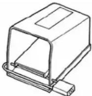
Figure 1 – Locked Foot Switch
Description, Specifications, Standard Equipment and Accessories
Description
The RIDGID Model No. 916 Roll Groover forms standard roll grooves in steel, stainless steel and aluminum pipe. The No. 916 is a portable lightweight roll groover designed for 1^1/4 - 6" Schedule 10 pipe ( 1^1/4 - 3" Schedule 40 pipe); also can be adapted for 1" Schedule 10, 1" Schedule 40, 2" - 6" copper types K, L, M, and DWV with a roll change. The grooves are formed by a grooving roll fed into a drive roll to the specifications required for mechanical coupling systems. The only adjustment needed is for the depth of the groove.
The No. 916 Roll Groover is designed for specific use with the RIDGID No. 300 Power Drive, 300 Compact, 535M, 535A and 1822-I Threading Machines. Different 916 models are required for every power source or mounting operation.
CAUTION When properly used, the Model 916 makes grooves that are dimensionally within the specifications of AWWA C606-87. Selection of appropriate materials and joining methods is the responsibility of the system designer and/or installer. Before any installation is attempted, careful evaluation of the specific service environment, including chemical environment and service temperature, should be completed.
Specifications
Roll Grooving Capacity
- 1^1/4'' - 6" Schedule 10
- 1^1/4 - 3" Schedule 40
(See Table II for Wall Thickness)
- 2" - 6" Copper Types (K,L,M, DWV)
- 1 "Schedule 10
- 1 "Schedule 40
Depth Adjustment .....Adjustment Screw
Actuation....Integral Single Stroke Handle Mechanism
Power Drive
Mounting ....300 Power Drive, 1822 -I Threading Machine, 535M, 535A Threading Machines, 300 Compact Threading Machine
Weight......33 lbs.
Standard Equipment
Grooving Roll....1 ^1/4 " - 6" (1 ^1/4 " - 3" Schedule 40, 6" Schedule 10)
Driving Roll .... 1^1/4 " - 6" (1 ^1/4 " - 3" Schedule 40, 6" Schedule 10)
Feed Handle......Tubular Design
Drive Bar Adapter......(When Required)
916 Roll Grooving Models
| Catalog No. | Model Weight | |||
| No. | Description | lb. | kg. | |
| 45007 | 916 | Roll Groover for 300 Power Drive | 33 | 15,0 |
| 46852 | 916 | Roll Groover for Copper Tubing for 300 P.D. | 34 | 15,5 |
| 60382 | 916 | Roll Groover for 535 | 33 | 15,0 |
| 48307 | 916 | Roll Groover for 1822 | 33 | 15,0 |
| 48307 | 916 | Roll Groover for 300 Compact Mounted on 100, 150 and 200 Stands | 33 | 15,0 |
| 45007 | 916 | Roll Groover for 300 Compact Mounted on 250 Stand (Also requires 67662 Adapter Bracket) | 33 | 15,0 |
| Accessories | ||||
| 45347 | — | Roll Set for 1" Schedule 10, 40 (Optional) | 6 | 2,6 |
| 45352 | — | Roll Set for Copper (Optional) | 6 | 2,6 |
| 69667 | — | Roll Set for 1/4" - 1/2" AWWA (Optional) | 6 | 2,6 |
| 69692 | — | Roll Set for 2" - 6" AWWA (Optional) | 6 | 2,6 |
| 67662 | — | Adapter Bracket for 300 Compact | 30 | 13,6 |
| 76822 | — | English Diameter Tape | 0.3 | 0,1 |
| 76827 | — | Metric Diameter Tape | 0.3 | 0,1 |
Roll Groover Assembly Instructions
WARNING

The 916 Roll Groover should only be used with the following power drives and threading machines.
• 300 Power Drive (38 and 57 RPM)
• 535 Threading Machine (38 and 54 RPM)
• 1822 Threading Machine
• 535 Automatic Threading Machine
• 300 Compact Machine
Use only power drives and threading machines that operate at 58 RPM or less. Higher speed machines increase risk of injury.
To prevent serious injury, proper assembly of the Roll Groover is required. The following procedures should be followed:
Installing on No. 300 Power Drive
- Remove carriage or other attachments from the 300 Power Drive.
-
Fully open front chuck of power drive.
-
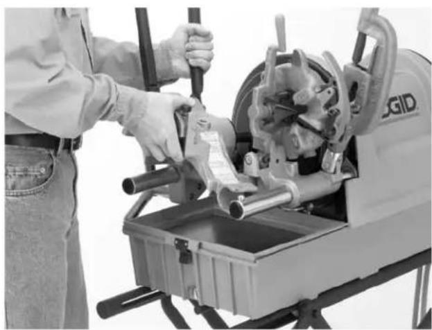
Position 916 on far side carriage rail and lower onto near side rail. (Figure 2)
- Align the notched flats of drive shaft with the jaws on the No. 300 Power Drive chuck.
- Tighten front chuck securely on drive shaft.
natural_image
Person in work uniform operating a mechanical device with rotating components (no visible text or symbols)Figure 2 – Mounting on No. 300 Power Drive
Installing Drive Bar Adapter For 1822-I, 535 or 300 Compact Threading Machines
NOTE! Drive bar adapter must be installed on the 916 Roll Groover when using the 535A, 535M, 1822I or the 300 Compact Threading Machines as a power source.
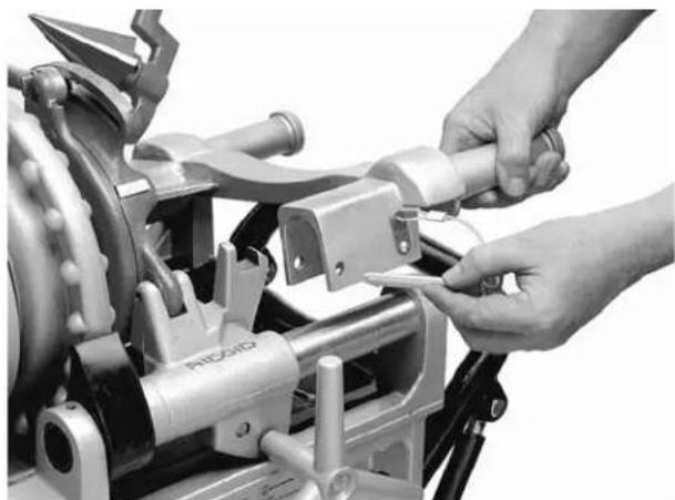
Installing Drive Bar Adapter
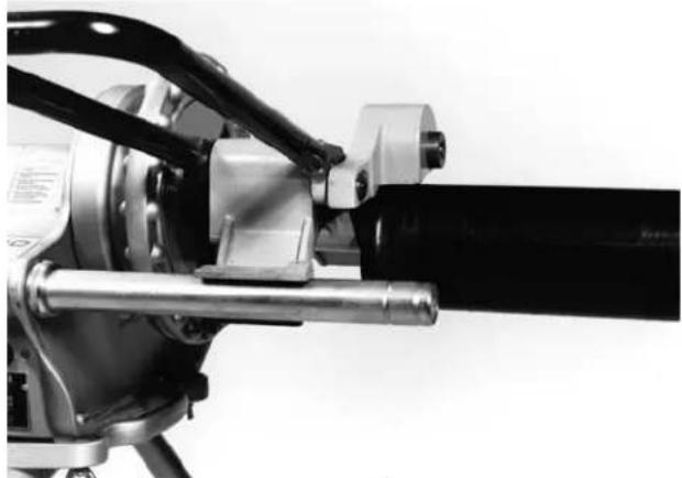
- Install drive bar adapter on roll groover drive shaft. Align set screws with flats on drive shaft and tighten screws.
natural_image
Technical line drawing of a mechanical lever assembly (no text or symbols)Figure 3 – Tighten Set Screws
Installing on 535A, 535M, 1822-I or 300 Compact Threading Machines Mounted on 100, 150 or 200 Stands
NOTE! 535 Threading Machines use the Model 916 Catalog No. 60382. Attached to the groover is a mounting plate that properly positions the unit on the rails of the 535. 1822I and the 300 Compact Threading Machines use the Model 916 Catalog No. 48307. The lower
roll housing is specifically designed for mounting of the rails of these machines.
- Position carriage towards front chuck and swing carriage tools to the rear position.
CAUTION Position reamer inside the die head to prevent accidental contact.
- Fully OPEN front chuck.
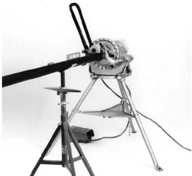
- Place 916 on far side of carriage rail, lower onto front rail (Figure 4).
- Position base so that drive bar feeds into open chuck and tighten front chuck onto drive bar.
⚠ WARNING Drive bar must be centered in front jaws.
natural_image
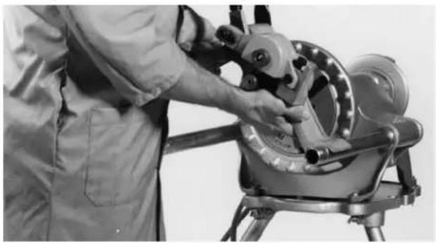
Person operating a large industrial machine with pipes and tools (no visible text or symbols)Figure 4 – Mounting on No. 1822-I Threading Machine (Same applies to Models 300 Compact and 535 Threading Machines)
Installing on 1822-I Threading Machine Mounted on 1406 Stand
NOTE! 1822I Threading Machines use the Model 916 Catalog No. 48307.
- Position carriage towards front chuck and swing tools to the rear position.
CAUTION Position reamer inside the die head to prevent accidental contact.
- Front chuck must be open. Position 916 so that the base slides onto the support rails and drive bar feeds into open chuck.
⚠ WARNING Drive bar must be centered in front jaws.
- Tighten chuck jaws securely onto drive bar.
Installing on 300 Compact Threading Machine with the 250 Stand.
NOTE! 300 Compact Threading Machines use the Model 916 Catalog No. 45007 and Adapter Bracket No. 67662 when mounted on a 250 Stand.
- Position carriage towards front chuck and swing carriage tools to rear position.
CAUTION Position reamer inside the die head to prevent accidental contact.
- Place the adapter bracket onto the rails of the 300 Compact and lock into place using the attached pin (Figure 5).
⚠ WARNING Adapter bracket must be used with the 250 Stand to provide clearance for the pipe. Failure to use this bracket will result in the pipe hitting the stand.
natural_image
Close-up of hands operating a mechanical tool with a clip labeled 'PICKED' (no visible text or symbols beyond label)Figure 5 – Attaching Adapter Bracket to 300 Compact Threading Machine
-
Place the 916 on the arms of the adapter.
-
Position base so that the drive bar feeds into the open chuck.
-
Tighten chuck jaws securely into drive bar.
⚠ WARNING Drive bar must be centered in front chuck jaws. Drive bar must be securely held in chuck.
NOTE! Before transporting the 300 Compact using the No. 250 Stand, the 916 Roll Groover and 916 Roll Groover Adapter Bracket MUST be disassembled and removed from the machine. If left intact, these items will not allow the No. 250 Stand to lock in the folded position.
Machine Inspection
WARNING


Do not use this Roll Groover with a power drive or threading machine that does not have a foot switch.
To prevent serious injury, inspect your Roll Groover and machine. The following inspection procedures should be performed on a daily basis.
-
Make sure machine is unplugged and the directional switch is set to the OFF position.
-
Make sure the foot switch is present and attached to the machine.
-
Inspect the power cord and plug for damage. If the plug has been modified, is missing the grounding pin or if the cord is damaged, do not use the machine until the cord has been replaced.
-
Make sure the Roll Groover is properly attached to the power drive or threading machine. Drive bar must be centered and securely held in the front chuck.
-
Inspect the Roll Groover for any broken, missing, misaligned or binding parts as well as any other conditions which may affect the safe and normal operation of this equipment. If any of these conditions are present, do not use the Roll Groover until any problem has been repaired.
-
Lubricate the Roll Groover if necessary according to the Maintenance Instructions.
-
Use groover rolls and accessories that are designed for your Roll Groover and meet the needs of your application. The correct groover tools and accessories allow you to do the job successfully and safely. Accessories suitable for use with other equipment may be hazardous when used with this Roll Groover.
-
Clean any oil, grease or dirt from all equipment handles and controls. This reduces the risk of injury due to a tool or control slipping from your grip.
-
Inspect the groove rolls to insure they are not damaged or worn. Wom groover rolls can lead to pipe slippage and poor quality grooves.
Machine and Work Area Set-Up
WARNING

natural_image
Four black-and-white pictograms showing explosive, running, gear, and trash symbols (no text or labels)To prevent serious injury, proper set-up of the machine and work area is required. The following procedures should be followed to set-up the machine:
-
Locate a work area that has the following:
-
Adequate lighting
- No flammable liquids, vapors or dust that may ignite.
• Grounded electrical outlet - Clear path to the electrical outlet that does not contain any sources of heat or oil, sharp edges or moving parts that may damage electrical cord.
- Dry place for machine and operator. Do not use the machine while standing in water.
- Level ground
- Clean up the work area prior to setting up any equipment. Always wipe up any oil that may be present.
- Place machine on a flat, level surface. Be sure the machine, stand and groover are stable.
- Properly support the pipe with pipe stands. Use two pipe stands to groove pipe over 36".
⚠ WARNING Failure to properly support the pipe can result in the unit tipping or the pipe falling.
- Make sure FOR/OFF/REV switch is in the OFF position.
- Position the foot switch so that the operator can safely control the machine, roll groover and workpiece. It should allow the operator to do the following:
- Stand with left hand on feed handle.
- Use the foot switch with his left foot.
- Have convenient access to the groover without reaching across the machine.
Machine is designed for one person operation.
- Plug the machine into the electrical outlet making sure to position the power cord along the clear path selected earlier. If the power cord does not reach the outlet, use an extension cord in good condition.
⚠ WARNING To avoid electrical shock and electrical fires, never use an extension cord that is damaged or does not meet the following requirements.
- The cord has a three-prong plug similar to shown in Electrical Safety section.
- The cord is rated as "W" or "W-A" if being used outdoors.
- The cord has sufficient wire thickness (14 AWG below 25'/12AWG 25' - 50'). If the wire thickness is too small, the cord may overheat, melting the cord's insulation or causing nearby objects to ignite.
⚠ WARNING To reduce risk of electrical shock, keep all electrical connections dry and off he ground. Do not touch plug with wet hands.
-
Check the unit to insure it is operating properly.
-
Flip the directional switch to FOR (Forward). Press and release the foot switch. Check that the groove roll rotates in a counterclockwise direction as you are facing the groover. Have the power drive or threading machine serviced if it rotates in the wrong direction or if the foot switch does not control its stopping or starting.
- Depress and hold the foot switch. Inspect the moving parts for misalignment, binding, odd noises or any other unusual conditions that may affect the safe and normal operation of the machine. If such conditions are present, have the roll groover drive serviced.
- Check the speed of the machine to insure it rotates under 58 RPM. Higher speed machine increases the risk of injury.
- Flip the directional switch to REV (Reverse) (Except 1822-I and 535 Automatic machines). Press and release the foot switch. Check that the drive roll rotates in a clockwise direction as you are facing the roll groover.
-
Release the foot switch and flip the directional switch to OFF.
-
Check the groove and drive rolls to insure they are the correct size.
CAUTION Use of roll sets on both carbon and stainless steel pipe can lead to contamination of the stainless steel material. This contamination could cause corrosion and premature pipe failure. To prevent ferrous contamination, use roll sets dedicated for stainless steel grooving.
Operating the 916 Roll Groover
WARNING
Do not wear gloves or loose clothing when operating a Roll Groover. Keep sleeves and jackets buttoned. Do not reach across the machine or pipe.
Do not use this Roll Groover with a Power Drive or Threading Machine that has a broken or missing foot switch. Always wear eye protection to protect eyes from dirt and other foreign objects.
Keep hands away from grooving rolls. Do not wear loose fitting gloves when operating groover. Use pipe stands to support pipe.
When grooving, keep hands away from end of pipe. Do not reach inside pipe end.
Pipe Preparation
- Pipe ends must be cut square. Do not use cutting torch.
- Pipe out-of-roundness must not exceed the total O.D. tolerance listed in groove specifications, Table I.
NOTE! Determine out-of-roundness by measuring maximum and minimum O.D. at 90 degrees apart.
- All internal or external weld beads, flash or seams must be ground flush at least 2" back from pipe end.
NOTE! Do not cut flats on gasket seat area.
Pipe/Tubing Length
Chart A lists the minimum length of pipe or tubing to be grooved and the maximum length to be grooved with (1) pipe stand.
Groovable Pipe Lengths - Inches Nom. Min. Max. Nom. Min. Max. Size Length Length Size Length Length
| 1 8 36 4 | 8 | 36 | |||
| 1^1/_4 | 8 | 36 | 4^1/_2 | 8 | 32 |
| 1^1/_2 | 8 | 36 | 5 | 8 | 32 |
| 2 8 36 | 6 O.D. | 10 | 30 | ||
| 2^1/_2 | 8 36 6 | 10 | 28 | ||
| 3 | 8 | 36 | |||
| 3^1/_2 | 8 | 36 | |||
Chart A – Minimum/Maximum Pipe Length
⚠ WARNING Grooving pipe below 8" in length increases the risk of fingers being crushed in the grooving rolls.
Pipe Set-Up
- Pipe or tubing longer than the specified maximum lengths listed in Chart A must be supported with 2 pipe stands. The second pipe support should be located ^3/4 of pipe length from roll groover.
⚠ WARNING Failure to use two stands may result in unit tipping or the pipe falling.
- Lift up on feed handle and place pipe on drive roll and pipe support.
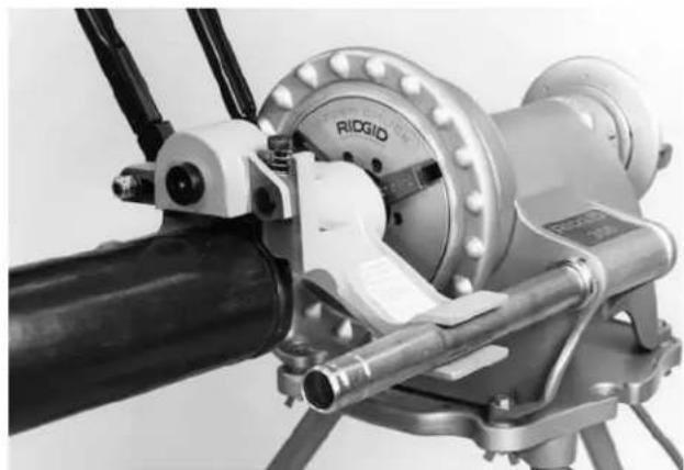
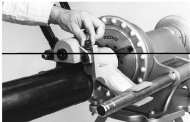
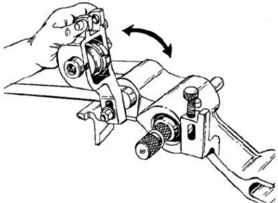
- Square pipe and pipe support to roll groover making sure pipe is flush against drive roll flange. (Figure 6)
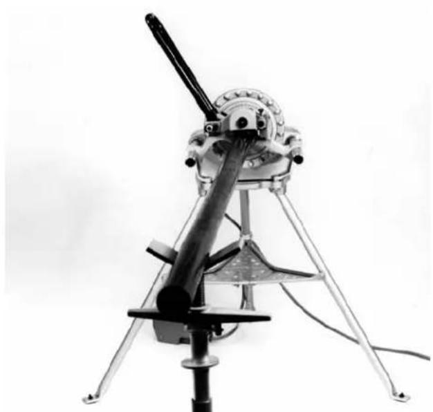
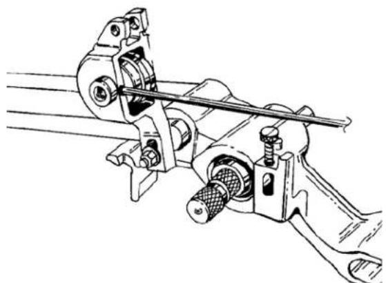
- Level pipe by adjusting pipe stand (Model 300PD, 535) (Figure 7). See tip for 1822 and 300 Compact grooving on page 10.
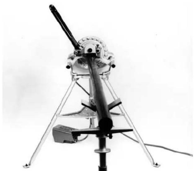
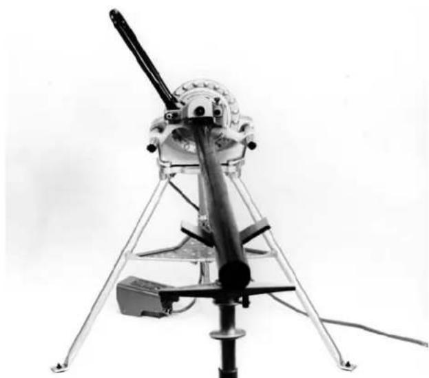
- Slightly offset (approximately 12^ ) pipe and pipe stand toward operator when the power source operates in REVERSE mode (Figure 8).
NOTE! If power source runs in FORWARD offset pipe 12^ away from operator. (Figure 8)
natural_image
Close-up of a mechanical assembly with metallic components and a black cylindrical shaft (no visible text or symbols)Figure 6 – Square Pipe & Pipe Support
natural_image
Black-and-white photo of a mechanical device with tripod base and lever mechanism (no visible text or symbols)Figure 7 – Leveling Pipe
natural_image
Black-and-white photo of a mechanical tripod-mounted device with a long-handled tool, no visible text or symbols.Figure 8A – Operating Machine in REVERSE (REV) Position
natural_image
Black-and-white photo of a mechanical tripod-mounted device with a lever and base, no visible text or symbols.Figure 8B – Operating Machine in FORWARD (FOR) Position
Adjusting Roll Groove Depth
NOTE! To obtain the proper groove diameter, a test groove should be performed when setting up or changing pipe sizes.
- Lift feed handle upward. (Figure 9)
natural_image
Close-up of a mechanical testing device with a black cylindrical component and a white cylindrical housing (no visible text or symbols)Figure 9 – Feed Handle in UP Position
- Fully loosen depth adjustment screw. (Figure 10)
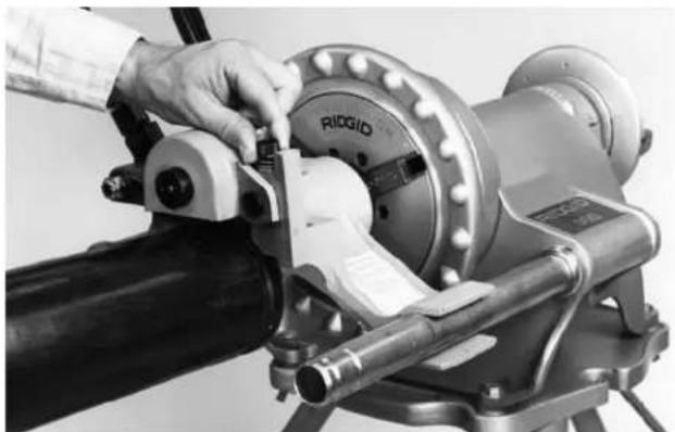
natural_image
Close-up of a person operating a Ridgid industrial machine tool (no visible text or symbols)Figure 10 – Loosen Depth Adjustment Screw
- Tighten down depth adjustment screw the number of turns indicated in Chart B. (Figure 11)
NOTE! Chart B indicates adjustment needed when using the 916's standard roll set. See Chart D on Page 12 for special note on 1^1/4 , 1^1/2 AWWA grooving and 1'' pipe grooving. Chart C is used when grooving copper.
natural_image
Close-up of a hand operating a mechanical pipe fitting with a circular component (no visible text or symbols)Figure 11 - Tighten Depth Adjustment Screw
Pipe Diameter Reference
Pipe Schedule 10 Schedule 40
Diameter Minimum Minimum
No. of Turns No. of Turns
| 6 | 212 | N/A |
| 4 | 234 | N/A |
| 3^1/_2 | 234 | N/A |
| 3 | 212 | ^3/_4 |
| 2^1/_2 | 212 | 1 |
| 2 | 212 | 1^1/_2 |
| 1^1/_2 | 212 | 1^3/_4 |
| 1^1/_4 | 234 | 1^3/_4 |
Chart B – Pipe Diameter and Turns
NOTE! Additional adjustment may be necessary to achieve proper depth. Chart above is for reference only.
Forming the Roll Groove
CAUTION Pipe wall thickness cannot exceed the maximum wall thickness specified in the "Pipe Maximum and Minimum Wall Thickness" Table II.
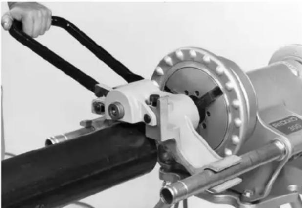
- Flip the directional switch from OFF and step on power drive or threading machine foot switch while applying slight downward pressure on the feed handle.
natural_image
Close-up of a mechanical assembly with a hand operating a tool, featuring a black cylindrical component and a metallic housing (no visible text or symbols)Figure 12 – Forming the Roll Groove
⚠ WARNING If pipe begins to "walk off" the drive roll, stop the machine and check "Pipe Set-Up" procedure.
- To help prevent "walking", apply pressure on pipe with right hand, away from operator when running the power drive or machine in FORWARD mode, toward operator when running the power drive or machine in REVERSE mode.
NOTE! If power source runs in FOR position, push the pipe away from operator. If power source runs in REV, pull the pipe towards operator.
- With pipe tracking properly and backside of pipe against drive roll flange, step on foot switch and con-
tinue downward pressure until feed handle rests on the base of 916 Roll Groover.
NOTE! Do not overfeed upper groove roll. Maintain constant downward pressure, pausing to allow one pipe revolution before increasing downward pressure.
-
After feed handle comes to rest on base of 916 Roll Groover allow two (2) complete pipe revolutions to even out groove depth.
-
Release foot switch and slip directional switch to OFF.
-
Pull feed handle upward and check groove diameter (See Table I).
NOTE! Two measurements 90 degrees apart should equal the "C" dimension or measure with a PI tape.
- To decrease groove diameter, tighten depth adjustment screw. To increase groove diameter, loosen depth adjustment screw.
NOTE! Once groove depth is determined, additional grooves will have the same depth.
- Periodically check groove depth with a "pi" or diameter tape. Coupling should fully seat in the groove without binding or excessive play.
NOTE! Pipe exceeding Fitting Manufacturer's "Maximum Flare Specifications" may prevent assembly of the couplings pad to pad, allowing possible pipe separation that could result in property damage. Also, joint leakage may result due to excessive gasket distortion/damage. Check to Fitting Manufacturer's specifications.
Model No. 916 Roll Grooving Tips
-
If pipe tends to walk off drive roll, increase offset dimension.
-
If drive roll flange shaves pipe end, decrease offset dimensions.
-
If pipe end flare is excessive, lower pipe end to level with roll groover.
-
If pipe wobbles and/or walks off drive roll, raise pipe end to level with groover.
-
Short lengths of pipe (under three feet) may require slight pressure to maintain the 12 degree offset dimension.
NOTE! When grooving pipe longer than 36" on Models 300 Compact or 1822-I Threading Machines that are mounted on folding stands, adjust the pipe to the same angle of the 916's drive shaft (Figure 13).
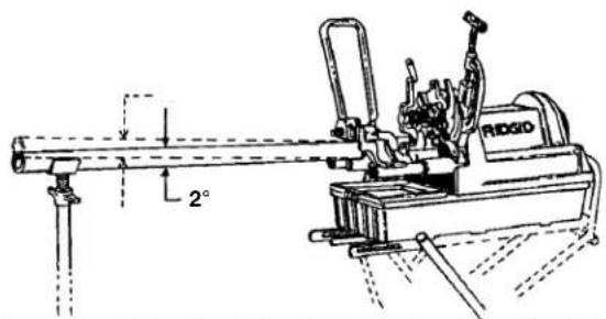
Figure 13 – Adjusting Pipe to Same Angle as Machine
Grooving Short Lengths of Pipe
- When running machine in forward direction, exert pressure on pipe away from operator.
- When running machine in reverse, exert pressure on pipe toward operator.
⚠ WARNING Do not attempt to groove any pieces of pipe shorter than 8". Increases risk of fingers being crushed in the grooving rolls. Do not reach inside pipe end.
Removing and Installing
Removing and Installing Groove Roll
NOTE! As groove dimensions are determined by the roll set geometry, specific roll sets are required when grooving the following:
2" - 6" Copper Tubing Types (K, L, M, DWV)
1" Schedule 10 & 40
1^1/4 - 6" Schedule 10 ( 1^1/4 - 3" Schedule 40)
2" - 3" Schedule 40, 2" - 6" Schedule 10 AWWA
1^1/4 - 1^1/2 AWWA Schedule 10 & 40
⚠ WARNING Make sure power drive or threading machine is unplugged from power source before changing the roll sets or removing the roll groover.
- Remove E-Ring that holds pivot pin. (Figure 14)
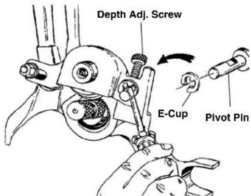
Figure 14 – Remove E-Ring
- Push pivot pin back until stops.
- Loosen depth adjustment screw.
- Remove pivot pin.
- Raise up groove roll housing. (Figure 15)
natural_image
Illustration of a hand using a mechanical clamp to adjust or install a component, showing no text or symbols.Figure 15 – Raise Up Roll Housing
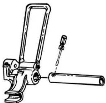
- Loosen set screw that holds groove roll shaft. (Figure 16)
natural_image
Technical line drawing of a mechanical assembly with no visible text or symbolsFigure 16 – Loosen Set Screw
- Remove groove-roll shaft and groove roll.
- Install proper groove roll in groove roll housing. Section of the groove roll that forms the groove goes towards the main housing.
- When tightening set screw make sure it mates with drill point in shaft.
10 Re-install roll housing by reversing steps 5-1.
Removing or Installing Drive Roll
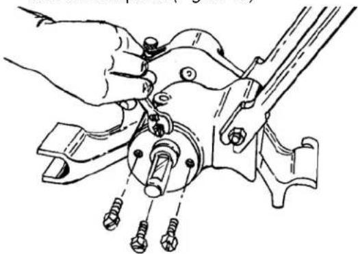
- Remove 4 bolts that hold rear bearing retaining plate and remove plate. (Figure 17)
natural_image
Technical line drawing of a mechanical assembly with hands adjusting components (no text or symbols)Figure 17 – Remove Retaining Plate
- With mallet, lightly tap on front of drive shaft to release shaft and rear bearing from unit.
- Pull drive shaft and bearing from unit, and replace with proper shaft.
NOTE! Replacement drive shaft come equipped with rear bearing.
Roll Grooving Copper with No. 916
Tubing Preparation
- Copper tubing ends must be cut square.
- Tubing out-of-roundness must not exceed the total O.D. tolerance listed in groove specifications.
NOTE! Determine out-of-roundness by measuring maximum and minimum O.D. at 90 degrees apart. Make sure that copper drive and groove rolls are installed before attempting to roll groove copper.
Forming Roll Groove
- Set adjustment screw for depth required. (See Chart C below.)
Depth Adjustment Chart for Copper Roll Set
| Number of Turns | ||||
| Diameter K | L | M | DWV | |
| 2'' | 4 | 4^1/_4 | 4^1/_2 | — |
| 2^1/_2'' | 3^1/_2 | 4 | 4^1/_4 | — |
| 3'' | 3^1/_4 | 3^1/_2 | 4^1/_4 | 4^3/_4 |
| 4'' | 2^1/_2 | 3^1/_4 | 3^1/_2 | 4^1/_2 |
| 5'' | 1^3/_4 | 2^3/_4 | 3^1/_4 | 4^1/_4 |
| 6'' | 1^1/_4 | 2^1/_2 | 3 | 4^1/_4 |
Chart C – Depth Adjustment Chart for Copper Pipe
NOTE! Additional adjustment may be necessary to achieve proper groove diameter. Chart above is for reference only
- Square copper tubing and pipe stand to roll groover, making sure the workpiece is flush against drive roll flange.
- Level copper tubing by adjusting pipe stand. Copper tubing and machine should both be leveled.
- Follow instruction in section "Forming the Roll Groove" on page 10.
Roll Grooving Smaller Diameter Steel Pipe
- Adjust feed screw for depth required. (See Chart D below.)
| Schedule 10 Schedule 40Diameter Minimum No. of Turns Minimum No. of Turns | ||
| 1" 5 | 4 | 14 |
| 1 14 " 3 | 12 | 3 |
| 1 12 " 3 | 34 | 3 12 |
Chart D
NOTE! Additional adjustment may be necessary to achieve proper depth. Chart above is for reference only.
- Follow instructions in section "Forming the Roll Groove" on page 10.
NOTE! 1 ^1/4 " and 1 ^1/2 " in Chart D refers to the use of optional AWWA roll set. See Chart B for adjustment when using standard roll set.
Accessories
⚠ WARNING Only the following RIDGID products have been designed to function with the 916 Roll Groover. Other accessories suitable for use with other tools may become hazardous when used on this Roll Groover.
To prevent serious injury, use only the accessories listed below.
| Catalog No. | Model No. | 916 Accessories |
| 45347 | — | Roll Set for 1" Schedule 10, 40 (Optional) |
| 45352 | — | Roll Set for Copper (Optional) |
| 69667 | — | Roll Set for 1 1/4" - 1 1/4" AWWA (Optional) |
| 69692 | — | Roll Set for 2" - 6" AWWA (Optional) |
| 67662 | — | Adapter Bracket for 300 Compact |
| 76822 | — | English Diameter Tape |
| 76827 | — | Metric Diameter Tape |
NOTE: A Roll Set Consists of a Groove Roll and a Drive Roll.
NOTE! See Ridge Tool catalog for listing of pipe stands.
Maintenance Instructions
⚠ WARNING Make sure machine is unplugged from power source before performing maintenance or making any adjustments.
Lubrication
Drive Shaft and Groove Roll Shaft Bearings.
Lubricate with multi-purpose grease through fittings located on groove roll shaft and lower roll housing after every roll change.
Machine Storage
⚠ WARNING Motor-driven equipment must be kept indoors or well covered in rainy weather. Store groover in a locked area that is out of reach of children and people unfamiliar with roll groover equipment. This machine can cause serious injury in the hands of untrained users.
Service and Repair
Service and repair work on this Roll Groover must be performed only by qualified repair personnel. Machine should be taken to a RIDGID Independent Authorized Service Center or returned to the factory. All repairs made by Ridge service facilities are warranted against defects in material and workmanship.
⚠ WARNING When servicing this machine, only identical replacement parts should be used. Failure to follow these instructions may create a risk of serious injury.
If you have any questions regarding the service or repair of this machine, call or write to:
Ridge Tool Company
Technical Service Department
400 Clark Street
Elyria, Ohio 44035-6001
Tel: (800) 519-3456
E-mail: rtctechservices@emerson.com
For name and address of your nearest Independent Authorized Service Center, contact the Ridge Tool Company at (800) 519-3456 or http://www.RIDGID.com
Table I. Standard Roll Groove Specifications ^1
NOTE! All Dimensions are in Inches.
| NOM. PIPE SIZE | PIPE DIAMETER | MIN. WALL THK. | GASKET SEAT+.015/-.030 | GROOVE WIDTH+.030/-.015 | GROOVE DIAMETER | NOM. GROOVE DEPTH REF2 | ||
| O.D. | TOL. | O.D. | TOL. | |||||
| 1 | 1.315 | +.013-.015 | .065 | .625 | .281 | 1.190 | +.000-.015 | .063 |
| 1^1/_4 | 1.660 | +.016-.015 | .065 | .625 | .281 | 1.535 | +.000-.015 | .063 |
| 1^1/_2 | 1.900 | +.019-.015 | .065 | .625 | .281 | 1.775 | +.000-.015 | .063 |
| 2 | 2.375 | +.024-.016 | .065 | .625 | .344 | 2.250 | +.000-.015 | .063 |
| 2^1/_2 | 2.875 | +.029-.016 | .083 | .625 | .344 | 2.720 | +.000-.015 | .078 |
| 3 OD | 3.00 | +.030-.018 | .083 | .625 | .344 | 2.845 | +.000-.015 | .078 |
| 3 | 3.50 | +.030-.018 | .083 | .625 | .344 | 3.344 | +.000-.015 | .078 |
| 3^1/_2 | 4.00 | +.030-.018 | .083 | .625 | .344 | 3.834 | +.000-.015 | .083 |
| 4 | 4.50 | +.035-.020 | .095 | .625 | .344 | 4.334 | +.000-.015 | .083 |
| 4^1/_2 | 5.00 | +.040-.020 | .095 | .625 | .344 | 4.834 | +.000-.015 | .083 |
| 5 | 5.563 | +.050-.022 | .109 | .625 | .344 | 5.395 | +.000-.015 | .084 |
| 6 OD | 6.00 | +.050-.022 | .109 | .625 | .344 | 5.830 | +.000-.015 | .085 |
| 6 | 6.625 | +.050-.024 | .109 | .625 | .344 | 6.455 | +.000-.015 | .085 |
- AS per AWWA C606-87
- Nominal Groove Depth is provided as a reference dimension. Do not use groove depth to determine acceptability.
Table II. Pipe Maximum and Minimum Wall Thickness
NOTE! All Dimensions are in Inches.
| Pipe Size Wall Thickness | CARBON STEEL OR STAINLESS STEELALUMINUM PIPE OR TUBE PIPE OR TUBE PVC PIPE | |||||
| Thickness Wall Thickness Wall Thickness | ||||||
| Min. Max. | Min. Max. Min. | Max. | ||||
| 1".065 .133 .065 .109 .133 .133 | ||||||
| 1 14 ".065 .140 .065 .140 .140 .140 | ||||||
| 1 12 " .065 .145 .065 .145 .145 .200 | ||||||
| 2".065 .154 .065 .154 .154 .218 | ||||||
| 2 12 " .083 .203 .083 .188 .203 .276 | ||||||
| 3".083 .216 .083 .188 .216 .216 | ||||||
| 3 12 " .083 .120 .083 .188 .226 .226 | ||||||
| 4".083 .120 .083 .188 .237 .237 | ||||||
| 5".109 .134 .109 .188 .258 .258 | ||||||
| 6".109 .134 .109 .188 .280 .280 | ||||||
Table III. Troubleshooting
| PROBLEM CAUSE CORRECTION | ||
| Roll Groove too narrow or too wide. | Incorrect size of Grooving and Driving Rolls. | Install correct size of Grooving and Driving Rolls. |
| Mismatched Grooving and Driving Rolls. | Match Grooving and Driving Rolls. | |
| Grooving Roll and/or Driving Roll worn. | Replace worn Roll. | |
| Rolled Groove not perpendicular to pipe axis. | Pipe length not straight. | Use straight pipe. |
| Pipe end not square with pipe axis. | Cut pipe end square. | |
| Pipe will not track while grooving. | Pipe not level. | Adjust stand to level pipe. |
| Pipe axis not offset 1/2 degree from Driving Roll axis. | Offset pipe 1/2 degree. | |
| Groover not level. | Level Groover. | |
| Pipe flared at grooved end. | Pipe not level. | Adjust stand to level pipe. |
| Pipe drifts back and forth on Driving Roll axis while grooving. | Pipe length not straight. | Use straight pipe. |
| Pipe end not square with pipe axis. | Cut pipe end square. | |
| Pipe rocks from side to side on Driving Roll while grooving. | Pipe stands too close to end of pipe. | Move pipe stand in 1/4 distance from end of pipe. |
| Pipe end flattened or damaged. | Cut off damaged pipe end. | |
| Hard spots in pipe material or weld seams harder than pipe. | Hand feed Grooving Roll into pipe faster. | |
| Grooving Roll hand feed rate too slow. | Hand feed Grooving Roll into pipe faster. | |
| Power Drive speed exceeds 36 RPM. | Reduce speed to 36 RPM. | |
| Pipe supports Stand Rollers not in correct location for pipe size. | Position Pipe Stand Rollers for pipe size being used. | |
| Groover will not roll groove in pipe. | Maximum pipe wall thickness exceeded. | Check pipe capacity chart. |
| Wrong rolls. | Install correct rolls. | |
| Pipe material too hard. | Replace pipe. | |
| Adjustment screw not set. | Set depth. | |
| Power Drive does not supply required minimum torque. | Use RIDGID No. 300, 36-RPM Power Drive. | |
| Groover will not roll groove to required diameter. | Maximum pipe diameter tolerance exceeded. | Use correct diameter pipe. |
| Mismatched Grooving and Driving Rolls. | Match Grooving and Driving Rolls. | |
| Depth adjustment screw not set correctly. | Adjust depth setting. | |
| Pipe slips on Driving Roll. | Grooving Roll hand feed rate too slow. | Hand feed Grooving Roll into pipe faster. |
| Driving Roll knurling plugged with metal or worn flat. | Clean or replace Driving Roll. | |
| Groover will not rotate pipe while grooving. | Power Drive does not supply minimum required torque. | Use RIDGID No. 300, 36 RPM Power Drive, 535 or 1822-I Machine. |
| Chuck not closed on drive shaft flats. | Close chuck. | |
| Pipe raises or tends to tip Groover over backwards. | Pipe Support Stand too close to Groover. | Move pipe stand 1/4 distance in from outer end of pipe. |
Table IV. Copper Roll Groove Specifications
NOTE! All Dimensions are in Inches.
| 1 | 2 | 3 | 4 | 5 | ||||
| Nom. Tub Size Inches | Diameter O.D. | A Seat A ±.03 | B Width +.03 -.00 | C Max. Dia. +.00 -.02 | D Depth Ref. | Allow. Wall Thick. | T Allow. Flare Dia. | |
| Basic | Tolerance | |||||||
| 2'' | 2.125 | ±0.002 | 0.610 | 0.300 | 2.029 | 0.048 | 0.064 | 2.220 |
| 2^1/2'' | 2.625 | ±0.002 | 0.610 | 0.300 | 2.525 | 0.050 | 0.064 | 2.720 |
| 3'' | 3.125 | ±0.002 | 0.610 | 0.300 | 3.025 | 0.050 | DWV | 3.220 |
| 4'' | 4.125 | ±0.002 | 0.610 | 0.300 | 4.019 | 0.053 | DWV | 4.220 |
| 5'' | 5.125 | ±0.002 | 0.610 | 0.300 | 5.019 | 0.053 | DWV | 5.220 |
| 6'' | 6.125 | ±0.002 | 0.610 | 0.300 | 5.999 | 0.063 | DWV | 6.220 |
6
natural_image
Three industrial printing machines with different mechanical designs and colors, displayed against a plain background (no text or symbols visible)Table des matières
Lubrification ....31
Stockage de la machine....31
CONSERVEZ CES INSTRUCTIONS!
natural_image
Person in work uniform operating industrial machinery (no visible text or symbols)natural_image
Technical line drawing of a mechanical clamp or bracket assembly (no text or symbols)natural_image
Person operating a mechanical tool on an industrial machine (no visible text or symbols)natural_image
Close-up of hands operating a mechanical clamp or fixture with a plastic clip, no visible text or symbolsnatural_image
Close-up of a mechanical assembly with metal components and a cylindrical shaft (no visible text or symbols)natural_image
Black-and-white photo of a mechanical tripod-mounted device with a blade and central gear assembly (no visible text or symbols)natural_image
Black-and-white photo of a mechanical tripod-mounted device with a lever and base mount (no visible text or symbols)Figure 8A – Utilisation de la machine en MARCHE ARRIERE (REV)
natural_image
Black-and-white photo of a tripod-mounted scientific instrument with a lever and base, no visible text or symbols.natural_image
Close-up of a mechanical testing device with a black cylindrical component and a white cylindrical tool, no visible text or symbols.natural_image
Close-up of a hand operating a RiddiD-Rigdoming machine tool (no visible text or symbols)natural_image
Close-up of a hand operating a pipe fitting with a circular dial indicator (no visible text or symbols)natural_image
Close-up of a mechanical testing apparatus with a hand operating a tool, no visible text or symbolsnatural_image
Illustration of a hand using a mechanical clamp to adjust or install a component, showing no text or symbols.natural_image
Technical line drawing of a mechanical clamp or bracket assembly (no text or symbols)natural_image
Technical line drawing of a mechanical assembly with a hand adjusting components (no text or symbols)Technical Service Department
400 Clark Street
Elyria, Ohio 44035-6001
Tél. : (800) 519-3456
Mél : rtctechservices@emerson.com
natural_image
Three industrial printing machines with different mechanical designs, displayed against a plain background (no visible text or symbols)Índice
natural_image
Person in protective gear operating machinery (no visible text or symbols)natural_image
Technical line drawing of a mechanical lever assembly (no text or symbols)natural_image
Person operating a mechanical tool on a workbench, no visible text or symbolsnatural_image
Close-up of hands operating a mechanical device with a tool, no visible text or symbolsFigura 5 – Montaje del Caballete Adaptador a la Máquina Roscadora No. 300 Compacta
natural_image
Four black-and-white pictograms showing explosive, running figures, gear, and a broken object (no text or symbols)natural_image
Close-up of a mechanical assembly with metallic components and a cylindrical shaft (no visible text or symbols)natural_image
Black-and-white photo of a mechanical device with tripod base and lever mechanism (no visible text or symbols)natural_image
Black-and-white photo of a mechanical tripod-mounted device with a long lever and mounted components (no visible text or symbols)natural_image
Black-and-white photo of a vintage tripod-mounted scientific instrument with a mounted gun and base mount (no visible text or symbols)natural_image
Close-up of a mechanical pipe assembly with visible components and no readable text or symbolsnatural_image
Close-up of a hand operating a Riddio industrial machine tool (no visible text or symbols)natural_image
Close-up of a hand operating a mechanical pipe fitting with a metal bracket (no visible text or symbols)natural_image
Close-up of a mechanical testing machine with a hand operating the shaft (no visible text or symbols)natural_image
Illustration of a hand using a mechanical clamp to adjust or install a component, with no visible text or symbols.natural_image
Technical line drawing of a mechanical assembly with no visible text or symbolsnatural_image
Technical line drawing of a mechanical assembly with hands adjusting parts (no text or symbols)Technical Service Department
400 Clark Street
Elyria, Ohio 44035-6001
RIDGID ^e tools are warranted to be free of defects in workmanship and material.
How long coverage lasts
This warranty lasts for the lifetime of the RIDGID ^® tool. Warranty coverage ends when the product becomes unusable for reasons other than defects in workmanship or material.
How you can get service
To obtain the benefit of this warranty, deliver via prepaid transportation the complete product to RIDGE TOOL COMPANY, Elyria, Ohio, or any authorized RIDGID® INDEPENDENT SERVICE CENTER. Pipe wrenches and other hand tools should be returned to the place of purchase.
What we will do to correct problems
Warranted products will be repaired or replaced, at RIDGE TOOL'S option, and returned at no charge; or, if after three attempts to repair or replace during the warranty period the product is still defective, you can elect to receive a full refund of your purchase price.
What is not covered
Failures due to misuse, abuse or normal wear and tear are not covered by this warranty. RIDGE TOOL shall not be responsible for any incidental or consequential damages.
How local law relates to the warranty
Some states do not allow the exclusion or limitation of incidental or consequential damages, so the above limitation or exclusion may not apply to you. This warranty gives you specific rights, and you may also have other rights, which vary, from state to state, province to province, or country to country.
No other express warranty applies
This FULL LIFETIME WARRANTY is the sole and exclusive warranty for RIDGID ^2 products. No employee, agent, dealer, or other person is authorized to alter this warranty or make any other warranty on behalf of the RIDGE TOOL COMPANY.

Ce qui est couvert
Elyria, Ohio 44035-6001
U.S.A.

Qué cubre
Commercial & Residential Solutions