
R1500 - Drill RIDGID - Free user manual and instructions
Find the device manual for free R1500 RIDGID in PDF.
| Type | Drill Press |
| Marque | RIDGID |
| Modèle | R1500 |
| Alimentation | 120 V, 60 Hz, 8 A |
| Moteur | 3/4 HP, Induction |
| Vitesse à vide | 260 – 3,100 RPM (12 speeds) |
| Mandrin | 16 mm (5/8 in) |
| Course de la broche | 76 mm (3 in) |
| Diamètre de balayage | 381 mm (15 in) |
| Table | Tilts 0-45°, with scale |
| Lampe de travail | Yes, with switch |
| Interrupteur | With locking key |
| Mise à la terre | Required, 3-prong plug |
| Garantie | 3-year limited |
| Entretien | Regular lubrication of spindle, rack and posts |
| Accessoires fournis | Hex keys, switch key, chuck |
| Utilisation | Drilling wood, metal, plastic |
Frequently Asked Questions - R1500 RIDGID
User questions about R1500 RIDGID
0 question about this device. Answer the ones you know or ask your own.
Ask a new question about this device
Download the instructions for your Drill in PDF format for free! Find your manual R1500 - RIDGID and take your electronic device back in hand. On this page are published all the documents necessary for the use of your device. R1500 by RIDGID.
USER MANUAL R1500 RIDGID
To register your RIDGID product, please visit:
http://register.RIDGID.com
General Safety Rules 2-3
■ Specific Safety Rules 4
Symbols. 5
Electrical. 6
Features. 7
Assembly. 8-10
Operation. 10-12
Adjustments 12
■ Maintenance. 13
Troubleshooting 14
■ Warranty. 15
■ Illustrations 16-23
Parts Ordering / Service......Back Page

WARNING:
To reduce the risk of injury, the user must read and understand the operator's manual before using this product.
SAVE THIS MANUAL FOR FUTURE REFERENCE
TABLE DES MATIÈRES
***************
Read and understand all instructions. Failure to follow all instructions listed below, may result in electric shock, fire and/or serious personal injury.
READ ALL INSTRUCTIONS
■ KNOW YOUR POWER TOOL. Read the operator's manual carefully. Learn the applications and limitations as well as the specific potential hazards related to this tool.
■ GUARD AGAINST ELECTRICAL SHOCK BY PREVENTING BODY CONTACT WITH GROUNDED SURFACES. For example: pipes, radiators, ranges, refrigerator enclosures.
- KEEP GUARDS IN PLACE and in good working order.
- REMOVE ADJUSTING KEYS AND WRENCHES. Form habit of checking to see that keys and adjusting wrenches are removed from tool before turning it on.
- KEEP WORK AREA CLEAN. Cluttered areas and benches invite accidents. DO NOT leave tools or pieces of wood on the tool while it is in operation.
DO NOT USE IN DANGEROUS ENVIRONMENTS. Do not use power tools in damp or wet locations or expose to rain. Keep the work area well lit.
- KEEP CHILDREN AND VISITORS AWAY. All visitors should wear safety glasses and be kept a safe distance from work area. Do not let visitors contact tool or extension cord while operating.
■ MAKE WORKSHOP CHILDPROOF with padlocks, master switches, or by removing starter keys.
DON'T FORCE THE TOOL. It will do the job better and safer at the feed rate for which it was designed.
USE THE RIGHT TOOL. Do not force the tool or attachment to do a job for which it was not designed.
- USE THE PROPER EXTENSION CORD. Make sure your extension cord is in good condition. Use only a cord heavy enough to carry the current your product will draw. An undersized cord will cause a drop in line voltage resulting in loss of power and overheating. A wire gauge size (A.W.G.) of at least 14 is recommended for an extension cord 25 feet or less in length. If in doubt, use the next heavier gauge. The smaller the gauge number, the heavier the cord.
DRESS PROPERLY. Do not wear loose clothing, gloves, neckties, or jewelry. They can get caught and draw you into moving parts. Also wear protective hair covering to contain long hair.
ALWAYS WEAR EYE PROTECTION WITH SIDE SHIELDS WHICH IS MARKED TO COMPLY WITH ANSI Z87.1 WHEN USING THIS PRODUCT.
SECURE WORK. Use clamps or a vise to hold work when practical, it is safer than using your hand and frees both hands to operate the tool.
DO NOT OVERREACH. Keep proper footing and balance at all times.
- MAINTAIN TOOLS WITH CARE. Keep tools sharp and clean for better and safer performance. Follow instructions for lubricating and changing accessories.
- DISCONNECT TOOLS. When not in use, before servicing, or when changing attachments, blades, bits, cutters, etc., all tools should be disconnected from power source.
AVOID ACCIDENTAL STARTING. Be sure switch is off when plugging in any tool.
- USE RECOMMENDED ACCESSORIES. Consult the operator's manual for recommended accessories. The use of improper accessories may result in injury.
NEVER STAND ON TOOL. Serious injury could occur if the tool is tipped.
- CHECK DAMAGED PARTS. Before further use of the tool, a guard or other part that is damaged should be carefully checked to determine that it will operate properly and perform its intended function. Check for alignment of moving parts, binding of moving parts, breakage of parts, mounting and any other conditions that may affect its operation. A guard or other part that is damaged must be properly repaired or replaced by an authorized service center to avoid risk of personal injury.
NEVER LEAVE TOOL RUNNING UNATTENDED. TURN THE POWER OFF. Don't leave tool until it comes to a complete stop.
PROTECT YOUR LUNGS. Wear a face or dust mask if the cutting operation is dusty.
PROTECT YOUR HEARING. Wear hearing protection during extended periods of operation.
- DO NOT ABUSE CORD. Never carry tool by the cord or yank it to disconnect from receptacle. Keep cord from heat, oil, and sharp edges.
USE OUTDOOR EXTENSION CORDS. When tool is used outdoors, use only extension cords with approved ground connection that are intended for use outdoors and so marked.
NEVER USE IN AN EXPLOSIVE ATMOSPHERE. Normal sparking of the motor could ignite fumes.
INSPECT TOOL CORDS PERIODICALLY. If damaged, have repaired by a qualified service technician at an authorized service facility. The conductor with insulation having an outer surface that is green with or without yellow
stripes is the equipment-grounding conductor. If repair or replacement of the electric cord or plug is necessary, do not connect the equipment-grounding conductor to a live terminal. Repair or replace a damaged or worn cord immediately. Stay constantly aware of cord location and keep it well away from the rotating wheel.
INSPECT EXTENSION CORDS PERIODICALLY and replace if damaged.
■ GROUND ALL TOOLS. If tool is equipped with three-prong plug, it should be plugged into a three-hole electrical receptacle.
- CHECK WITH A QUALIFIED ELECTRICIAN or service personnel if the grounding instructions are not completely understood or if in doubt as to whether the tool is properly grounded.
USE ONLY CORRECT ELECTRICAL DEVICES: 3-wire extension cords that have 3-prong grounding plugs and 3-pole receptacles that accept the tool's plug.
DO NOT MODIFY the plug provided. If it will not fit the outlet, have the proper outlet installed by a qualified electrician.
- KEEP TOOL DRY, CLEAN, AND FREE FROM OIL AND GREASE. Always use a clean cloth when cleaning. Never
use brake fluids, gasoline, petroleum-based products, or any solvents to clean tool.
STAY ALERT AND EXERCISE CONTROL. Watch what you are doing and use common sense. Do not operate tool when you are tired. Do not rush.
DO NOT USE TOOL IF SWITCH DOES NOT TURN IT ON AND OFF. Have defective switches replaced by an authorized service center.
DO NOT OPERATE A TOOL WHILE UNDER THE INFLUENCE OF DRUGS, ALCOHOL, OR ANY MEDICATION.
WHEN SERVICING use only identical replacement parts. Use of any other parts may create a hazard or cause product damage.
USE ONLY RECOMMENDED ACCESSORIES listed in this manual or addendums. Use of accessories that are not listed may cause the risk of personal injury. Instructions for safe use of accessories are included with the accessory.
DOUBLE CHECK ALL SETUPS. Make sure bit is tight and not making contact with tool or workpiece before connecting to power supply.
- KEEP BITS CLEAN AND SHARP. Sharp bits minimize stalling. Dirty and dull bits may cause misalignment of the material and possible operator injury.
- KEEP HANDS AWAY FROM WORK AREA. Keep hands away from the bit. Restrain any loose clothing, jewelry, long hair, etc. that may become entangled in the bit.
DO NOT wear gloves, necktie, or loose clothing.
ALWAYS CLAMP WORKPIECE AND BRACE AGAINST COLUMN TO PREVENT ROTATION. Never use your hand to hold the object while drilling.
USE RECOMMENDED SPEED FOR DRILL ACCESSORY AND WORKPIECE MATERIAL.
BE SURE DRILL BIT OR CUTTING TOOL IS SECURELY LOCKED IN THE CHUCK.
ADJUST THE TABLE OR DEPTH STOP TO AVOID DRILLING INTO THE TABLE. Shut off the power, remove the drill bit, and clean the table before leaving machine.
DO NOT CONNECT TOOL TO POWER SOURCE OR OPERATEUNTILITISCOMpletelyASSEMBLED AND INSTALLED ACCORDING TO THE INSTRUCTIONS. If any part of your drill press malfunctions or has been damaged or broken, do not operate until the part is properly repaired or replaced.
NEVER PLACE YOUR FINGERS IN A POSITION WHERE THEY COULD CONTACT THE DRILL or other cutting tool if the workpiece should unexpectedly shift.
NEVER PERFORM ANY OPERATION by moving the head or table with respect to one another. Do not turn the motor switch ON or start any operation before checking that the head and table support lock handle is clamped tight to column and head and table support collars are correctly positioned.
BEFORE ENGAGING THE POWER SWITCH ON, MAKE SURE THE BELT GUARD IS DOWN AND THE CHUCK IS INSTALLED PROPERLY.
■ LOCK THE MOTOR SWITCH OFF WHEN LEAVING THE DRILL PRESS. Do not perform layout, assembly, or set-up work on the table while the cutting tool is rotating, switched on or connected to a power source.
IF THE POWER SUPPLY CORD IS DAMAGED, it must be replaced only by the manufacturer or by an authorized service center to avoid risk.
SAVE THESE INSTRUCTIONS. Refer to them frequently and use to instruct other users. If you loan someone this tool, loan them these instructions also.
| The following signal words and meanings are intended to explain the levels of risk associated with this product. | ||
| SYMBOL | SIGNAL | MEANING |
| DANGER: | Indicates a hazardous situation, which, if not avoided, will result in death or serious injury. | |
| WARNING: | Indicates a hazardous situation, which, if not avoided, could result in death or serious injury. | |
| CAUTION: | Indicates a hazardous situation, that, if not avoided, may result in minor or moderate injury. | |
| NOTICE: | (Without Safety Alert Symbol) Indicates information considered important, but not related to a potential injury (e.g. messages relating to property damage). | |
| Some of the following symbols may be used on this product. Please study them and learn their meaning. Proper interpretation of these symbols will allow you to operate the product better and safer. SYMBOL NAME DESIGNATION/EXPLANATION | ||
| Safety Alert Indicates a potential | personal injury hazard. | |
| Wet Conditions Alert Do not expose to rain or use in damp locations. | ||
| Read The Operator's Manual | To reduce the risk of injury, user must read and understand operator's manual before using this product. | |
| Eye Protection | Always wear eye protection with side shields marked to comply with ANSI Z87.1. | |
| V Volts Voltage | ||
| A Amperes Current | ||
| Hz Hertz Frequency (cycles per second) | ||
| W Watt Power | ||
| min Minutes | Time | |
| ~ | Alternating Current | Type of current |
| no | No Load Speed | Rotational speed, at no load |
| .../min | Per Minute | Revolutions, strokes, surface speed, orbits etc., per minute |
EXTENSION CORDS
Use only 3-wire extension cords that have 3-prong grounding plugs and 3-pole receptacles that accept the tool's plug. When using a power tool at a considerable distance from the power source, use an extension cord heavy enough to carry the current that the tool will draw. An undersized extension cord will cause a drop in line voltage, resulting in a loss of power and causing the motor to overheat. Use the chart provided below to determine the minimum wire size required in an extension cord. Only round jacketed cords listed by Underwriter's Laboratories (UL) should be used.
**Ampere rating (on tool data plate)
0-2.0 2.1-3.4 3.5-5.0 5.1-7.0 7.1-12.0 12.1-16.0
Cord Length Wire Size (A.W.G.)
| 25' | 16 | 16 | 16 | 16 | 14 |
| 50' | 16 | 16 | 16 | 14 | 14 |
| 100' | 16 | 16 | 14 | 12 | 10 |
**Used on 12 gauge - 20 amp circuit. NOTE: AWG = American Wire Gauge
When working with the tool outdoors, use an extension cord that is designed for outside use. This is indicated by the letters "W-A" or "W" on the cord's jacket.
Before using an extension cord, inspect it for loose or exposed wires and cut or worn insulation.

WARNING:
Keep the extension cord clear of the working area. Position the cord so that it will not get caught on lumber, tools or other obstructions while you are working with a power tool. Failure to do so can result in serious personal injury.

WARNING:
Check extension cords before each use. If damaged replace immediately. Never use tool with a damaged cord since touching the damaged area could cause electrical shock resulting in serious injury.
ELECTRICAL CONNECTION
This tool is powered by a precision built electric motor. It should be connected to a power supply that is 120 volts, 60Hz , AC only (normal household current). Do not operate this tool on direct current (DC). A substantial voltage drop will cause a loss of power and the motor will overheat. If the grinder does not operate when plugged into an outlet, double check the power supply.
SPEED AND WIRING
The no-load speed of this tool is approximately 3,000 rpm. This speed is not constant and decreases under a load or with lower voltage. For voltage, the wiring in a shop is as important as the motor's horsepower rating. A line intended only for lights cannot properly carry a power tool motor. Wire that is heavy enough for a short distance will be too light for a greater distance. A line that can support one power tool may not be able to support two or three tools.
GROUNDING INSTRUCTIONS
See Figure 1, page 16.
In the event of a malfunction or breakdown, grounding provides a path of least resistance for electric current to reduce the risk of electric shock. This tool is equipped with an electric cord having an equipment-grounding conductor and a grounding plug. The plug must be plugged into a matching outlet that is properly installed and grounded in accordance with all local codes and ordinances.

WARNING:
Improper connection of the grounding plug can result in a risk of electric shock. When repair or replacement of the cord is required, do not connect the grounding wire to either flat blade terminal. The wire with insulation having an outer surface that is green with or without yellow stripes is the grounding wire.
Do not modify the plug provided. If it will not fit the outlet, have the proper outlet installed by a qualified electrician. Improper connection of the equipment-grounding conductor can result in a risk of electric shock. The conductor with insulation having an outer surface that is green with or without yellow stripes is the equipment-grounding conductor. If repair or replacement of the electric cord or plug is necessary, do not connect the equipment-grounding conductor to a live terminal.
Check with a qualified electrician or service personnel if the grounding instructions are not completely understood, or if in doubt as to whether the tool is properly grounded.
Repair or replace a damaged or worn cord immediately.
This tool is intended for use on a circuit that has an outlet like the one shown in figure 1. It also has a grounding pin like the one shown.
PRODUCT SPECIFICATIONS
Input. 120 V, AC Only, 60 Hz, 8 Amps
Motor 3/4 HP Induction
No Load Speed. 260-3,100 r/min. (RPM)
KNOW YOUR DRILL PRESS
See Figure 2, page 16.
The safe use of this product requires an understanding of the information on the tool and in this operator's manual as well as a knowledge of the project you are attempting. Before use of this product, familiarize yourself with all operating features and safety rules.
BASE
Supports drill press. For additional stability, holes are provided in base to bolt drill press to floor.
BELT GUARD
Covers pulleys and belt during operation of drill press.
BELT TENSION HANDLE
Turn handle counterclockwise to apply tension to belt, turn handle clockwise to release belt tension. Refer to Assembly section "To Install the Idler Pulley" and "To Tension the Belts".
BELT TENSION LOCK
Tightening handle locks motor bracket support to maintain correct belt distance and tension.
BEVEL SCALE
Shows degree table is tilted for bevel operations. Scale is mounted on table support. It is to be used for quick reference where accuracy is not critical.
CHUCK
Holds drill bit or other recommended accessory to perform desired operations.
COLLAR
Holds the rack to the column. Rack remains movable in collar to permit table support movements.
COLUMN SUPPORT
Supports column, guides rack, and provides mounting holes for column to base.
Number of Speeds. 12
Chuck Size. 5/8 in.
Spindle Travel 3 in.
DEPTH SCALE
Shows depth of hole being drilled in inches.
DEPTH SCALE LOCK
Locks the depth scale to selected depth.
FEED HANDLE
For moving the chuck up or down. One or two of the handles may be removed if necessary whenever the workpiece is of such unusual shape that it interferes with the handles.
RACK
Combines with gear mechanism to provide easy elevation of table by hand operated table crank.
SWITCH ASSEMBLY
This product has an easy access power switch. To lock the switch in the OFF (O) position, remove the switch key from the switch. Place the key in a location that is inaccessible to children and others not qualified to use the tool.
TABLE
Provides working surface to support workpiece.
TABLE BEVEL LOCK
Locks the table in any position from 0irc - 45irc
TABLE SUPPORT LOCK
Tightening locks table support to column. Always have it locked in place while operating the drill press.
WORKLIGHT
This tool comes equipped with a worklight that lights the work area.
UNPACKING
This product requires assembly.
Carefully lift tool from the carton and place it on a level work surface.
NOTE: This tool is heavy. To avoid back injury, keep your knees bent and lift with your legs, not your back, and get help when needed.

WARNING:
Do not use this product if any parts on the Loose Parts List are already assembled to your product when you unpack it. Parts on this list are not assembled to the product by the manufacturer and require customer installation. Use of a product that may have been improperly assembled could result in serious personal injury.
Inspect the tool carefully to make sure no breakage or damage occurred during shipping.
- Do not discard the packing material until you have carefully inspected and satisfactorily operated the tool.
- Remove the protective oil that is applied to the table and column. Use any ordinary household type grease and spot remover.
Apply a coat of paste wax to the table and column to prevent rust. Wipe all parts thoroughly with a clean dry cloth.
The machine is factory set for accurate drilling. After assembling it, check for accuracy. If shipping has influenced the settings, refer to specific procedures explained in this manual.
If any parts are damaged or missing, please call 1-866-539-1710 for assistance.

WARNING:
If any parts are damaged or missing, do not operate this tool until the parts are replaced. Use of this product with damaged or missing parts could result in serious personal injury.

WARNING:
Do not attempt to modify this tool or create accessories not recommended for use with this tool. Any such alteration or modification is misuse and could result in a hazardous condition leading to possible serious personal injury.

WARNING:
Do not connect to power supply until assembly is complete. Failure to comply could result in accidental starting and possible serious personal injury.

WARNING:
Do not lift the tool without help. Hold it close to your body. Keep your knees bent and lift with your legs, not your back. Ignoring these precautions can result in back injury.

WARNING:
To reduce the risk of injury from unexpected drill press movement, bolt it to the floor. Make sure and leave adequate room to fully open the belt guard. If the workpiece is too large to easily support with one hand, provide an auxiliary support.
TOOLS NEEDED
See Figure 3, page 17.
The following tools (not included or drawn to scale) are needed for assembly:
15/16 in. Socket Wrench
Adjustable Wrench
Combination Square
LOOSE PARTS LIST
See Figure 4, page 18.
The following items are included with the tool:
Head assembly 1
Collar. 1
Column. 1
Rack. 1
Column support 1
Base 1
Flat washer. 4
■ Lock washer. 4
Hex bolt. 4
Table support. 1
Table crank. 1
Feed handle 3
Table 1
Chuck. 1
Switch key. 1
Hex key 2
INSTALLING THE COLUMN TO THE BASE
See Figures 5 and 6, pages 17 and 18.
Using a hex wrench, loosen the set screws in the column support and insert the column.
- Secure the column in place by tightening the set screws. Do not overtighten.
Position base on flat surface. Remove protective covering and discard.
- Remove protective covering from column tube and discard. Place column assembly on base, and align holes in column support with holes in base.
Place a washer and flat washer on a hex head bolt.
Install the bolts with washers through each hole on the column assembly and into the base. Tighten bolts with an adjustable wrench.
INSTALLING THE TABLE CRANK AND GEAR RACK
See Figures 7 and 8, page 18.
- Slide table crank onto elevation worm shaft. Tighten set screw with a 3mm hex key. Do not overtighten.
NOTE: Set screw should be tightened against the flat section of the shaft.
NOTE: To minimize crank backlash, tighten table lock, rotate elevation worm shaft clockwise, then assemble crank tight against table support and tighten set screw.
Feed the gear rack through the slot in the table support so that the teeth are facing out and the longer smooth end faces up. The worm gear should engage the gear rack.
Using both hands, slide the entire assembly onto the column until the bottom of the gear rack is positioned against the column.
- Slide the column collar, bevel side down, over the column until the beveled side engages the beveled end of the gear rack. Tighten the set screw in the collar using the 3mm hex wrench. Do not overtighten.
NOTE: Table should be able to move side to side. Do not overtighten set screw.
- Slide the column collar over the column until the beveled side engages the beveled end of the gear rack.
- Check column collar for proper adjustment. Collar should not be angled on the column and it should be positioned so rack will slide freely in collar when table is rotated 360irc around column tube. If readjusted, only tighten set screw enough to keep collar in place.
Using the set screw, secure the column in place with a hex wrench. Do not overtighten.
INSTALLING THE TABLE
See Figure 9, page 19.
- Loosen table support lock and raise table support by turning table crank clockwise until support is at a working height level. Tighten table support lock.
- Remove protective covering from table and discard. Loosen table lock. Place table in table support and tighten table lock (located under table) by hand.
NOTE: If table won't fit into table support easily, pry open table support with a flat blade screwdriver.
INSTALLING THE HEAD ASSEMBLY
See Figure 10, page 19.
NOTE: This tool is heavy. To avoid back injury, keep your knees bent and lift with your legs, not your back, and get help when needed.
- Remove protective bag from head assembly and discard. Carefully lift head above column tube and slide onto the column making sure head slides down over column as far as possible. Align head with table and base.
Using a 5 mm hex key, tighten the head lock set screws on the right side of the head.
TENSIONING THE BELTS
See Figure 11, page 19.
Apply tension to belt by turning belt tension handle counterclockwise until belt deflects approximately 1/2 in. by thumb pressure at its center.
- Tighten belt tension lock handles.
NOTE: Over tensioning belt may cause motor not to start or damage bearings.
If belt slips while drilling, readjust belt tension.
INSTALLING THE FEED HANDLES
See Figure 12, page 20.
Screw the feed handle into the threaded hole in the hub. Tighten securely.
Repeat above step for remaining feed handles.
INSTALLING THE CHUCK
See Figure 13, page 20.
Clean the chuck and spindle with a clean cloth. Make sure there are no foreign particles sticking to these surfaces. The slightest piece of dirt on these surfaces will prevent the chuck from seating properly. This will cause the drill to "wobble".
Screw chuck onto spindle.
By hand, turn chuck counterclockwise to install.
NOTE:The force of drilling will tighten the chuck.
SQUARING THE TABLE TO HEAD
See Figure 14, page 20.
Insert precision round steel rod or straight drill bit approximately 3 in. long into chuck and tighten.
- Raise table to a working height and place a combination square flat on table beside rod or bit.
If an adjustment is necessary, loosen the table bevel lock bolt with an adjustable wrench.
Align the square to the bit by rotating table until the square and rod or bit are in line.
Retighten the table bevel lock.
OPERATION

WARNING:
Do not allow familiarity with tools to make you careless. Remember that a careless fraction of a second is sufficient to inflict severe injury.

WARNING:
Always wear eye protection with side shields marked to comply with ANSI Z87.1. Failure to do so could result in objects being thrown into your eyes, resulting in possible serious injury.

WARNING:
Do not use any attachments or accessories not recommended by the manufacturer of this tool. The use of attachments or accessories not recommended can result in serious personal injury.

WARNING:
To prevent the workpiece or the backup material from being torn from your hand while drilling, position them against the left side of the column. If the workpiece or the backup material are not long enough to reach the column, clamp them to the table. Failure to do this could result in personal injury.
SWITCH ASSEMBLY
See Figure 15, page 20.
This saw is equipped with a switch assembly that has a built-in locking feature. This feature is intended to prevent unauthorized and possible hazardous use by children and others.
To turn your saw on:
- With the switch key inserted into the switch, lift the switch to turn ON (I).
To turn your saw off:
Press the switch down to turn OFF (O).
To lock your saw:
Press the switch down.
- Remove the switch key from the switch and store in a safe, secure location.

WARNING:
ALWAYS remove the switch key when the tool is not in use and keep it in a safe place. In the event of a power failure, turn the switch OFF (O) and remove the key. This action will prevent the tool from accidentally starting when power returns.

WARNING:
ALWAYS make sure your workpiece is not in contact with the bit before operating the switch to start the tool. Failure to heed this warning may cause the workpiece to be kicked back toward the operator and result in serious personal injury.

WARNING:
To reduce the risk of accidental starting, ALWAYS make sure the switch is in the OFF (O) position before plugging tool into the power source.
INSTALLING/REMOVING BITS
See Figures 16 and 17, page 21.
To install bits:
Unplug your drill press.
Clean tapered surfaces on the chuck and spindle with a clean cloth. Make sure there are no foreign particles sticking to these surfaces.
- Open or close the chuck jaws to a point where the opening is slightly larger than the drill bit you intend to use.
Insert drill bit into chuck the full length of the jaws.

WARNING:
Do not insert drill bit into chuck jaws and tighten as shown in figure 17. This could cause drill bit to be thrown from your drill resulting in possible serious personal injury or damage to your chuck.
- Tighten chuck jaws securely. DO NOT use a wrench to tighten or loosen the chuck jaws.
NOTE: The force of drilling will tighten the chuck.
To remove bits:
Unplug your drill press.
Reverse above steps while holding bit firmly.
NOTE: If chuck is too tight to loosen by hand, use either a strap or spanner wrench to loosen.
USING THE WORKLIGHT
See Figure 18, page 21.
Swivel the worklight to desired position to shine maximum light on the workpiece.
Press the worklight on/off switch to the left to turn ON (1).
Press the worklight on/off switch to the right to turn OFF (O).
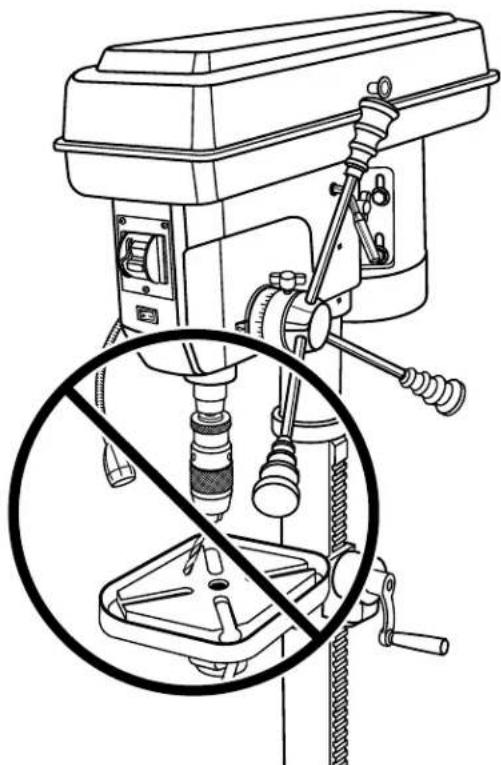
POSITIONING TABLE AND WORKPIECE
See Figures 18 and 19, page 21.
Lock the table to the column in a position so that the tip of the drill is just a little above the top of the workpiece.
Always place a piece of backup material (wood, plywood, etc.) on the table underneath the workpiece. This will prevent "splintering" or making a heavy burr on the underside on the workpiece as the drill breaks through.
To keep the backup material from spinning out of control, it must contact the left side of the column, as illustrated.
NOTE: For small pieces that cannot be clamped to the table, use a drill press vise (not included).

WARNING:
The vise must be clamped or bolted to the table to reduce the risk of injury from spinning work and vise or tool breakage.
MARKING HOLE LOCATION
Make a dent in the workpiece where you want the hole, using a center punch or a sharp nail.
Before turning the switch on, bring the drill down to the workpiece lining it up with the hole location.
DRILLING
Pull down on the feed handles with only enough effort to allow the drill to cut.
Feeding too slowly might cause the drill to burn.
Feeding too rapidly might stop the motor, cause the belt or drill to slip, tear the workpiece loose or break the drill bit.
- When drilling metal, it may be necessary to lubricate the tip of the drill bit with cutting oil or motor oil to prevent burning of the drill tip.
DRILLING TO A SPECIFIC DEPTH
See Figure 20, page 22.
To drill a blind hole (not all the way through) to a given depth, proceed as follows.
■ Mark the depth of the hole on the workpiece.
Loosen the depth scale lock.
- With the switch OFF (O), bring the drill bit down until the tip of lip of the bit are even with the mark.
- Turn the depth scale counterclockwise until it stops moving.
- Tighten the depth scale lock.
The drill bit will stop at this depth until the depth scale is readjusted.
DRILLING USING THE DEPTH SCALE
See Figure 21, page 22.
- With the power OFF (O), loosen the depth scale lock and turn the depth scale counterclockwise to zero.
- Place workpiece on table. Adjust table until the tip of the drill bit is just a little above the top of the workpiece.
- Turn the depth scale clockwise until the depth scale indicator points to the desired drilling depth on the depth scale.
Tighten the depth scale lock.
The chuck or drill will now be stopped after traveling downward the distance selected on the depth scale.
TO LOCK CHUCK AT DESIRED DEPTH
See Figure 22, page 22.
With the switch OFF (O), loosen the depth scale lock.
- Turn the feed handles until the chuck is at the desired depth. Hold feed handles at this position.
Turn the depth scale clockwise until it stops.
- Tighten the depth scale lock.
The chuck will now be held at this depth when the feed handles are released.
TILTING TABLE
See Figure 23, page 22.

WARNING:
To reduce the risk of injury from spinning work or tool breakage, always clamp workpiece and backup material securely to table before operating drill press with the table tilted.
To use the table in a bevel (tilted) position:
Loosen table bevel lock bolt.
Tilt table to desired angle by reading bevel scale. Retighten table bevel lock bolt.
To return table to original position:
- Loosen table bevel lock bolt, tilt table back to 0irc on bevel scale, then tighten table bevel lock bolt.
ADJUSTMENTS

WARNING:
Before performing any adjustment, make sure the tool is unplugged from the power supply. Failure to heed this warning could result in serious personal injury.
ADJUSTING TABLE HEIGHT
See Figure 23, page 22.
Hold the table with one hand then loosen the table support lock handle.
To raise the table, turn the table crank clockwise.
To lower the table, turn the table crank counterclockwise.
Once the table is in the desired position, retighten the table support lock handle.
CHANGING SPEEDS
The spindle speed is determined by the location of the belts on the pulleys inside the head assembly. The speed chart located on the inside of the belt guard shows the recommended speed and pulley configuration for each drilling operation:
- Loosen the two belt tension screws located on each side of the head assembly.
Pull the belt tension lever to release belt tension and to loosen the belts. - Open the head assembly cover and reposition the belt according to the speed chart. Close the cover.
Push the belt tension lever firmly back into position assuring drive belt is tight. While holding tension on the motor, retighten the two belt tension knobs securely.
ADJUSTING QUILL RETURN SPRING
See Figures 24 and 25, page 23.
NOTE: The return spring tension is set at the factory and should not require further adjustment.
NOTE: Turn the depth scale counterclockwise until it stops and tighten the depth scale lock.
Lower table for additional clearance.
Firmly hold the spring assembly against the head keeping it engaged with the lug while loosening and removing the outer nut only.
- Loosen inner nut (approximately 1/4 in. and disengage spring housing from the lug. Using both hands turn spring housing counterclockwise to the next notch and engage with the lug.
■ Finger tighten inner nut against spring housing. Do not overtighten as this will restrict quill movement.
- Loosen depth scale lock and check quill return by rotating feed handles, lowering quill.
Proper tension is achieved when quill returns gently to full up position when released from 3/4 in. depth.
If there is not enough tension on spring, repeat steps
- Moving only one notch each time and checking tension after each repetition.
After adjusting spring, replace outer nut and tighten to inner nut. But do not overtighten against inner nut.
- Check quill movement to make sure it is smooth and unrestricted. If movement is too tight, loosen outer nut and slightly loosen inner nut until unrestricted. Retighten outer nut.

WARNING:
When servicing, use only identical replacement parts. Use of any other part can create a hazard or cause product damage.

WARNING:
Always wear eye protection with side shields marked to comply with ANSI Z87.1 during product operation. If operation is dusty, also wear a dust mask.
GENERAL
Avoid using solvents when cleaning plastic parts. Most plastics are susceptible to damage from various types of commercial solvents and may be damaged by their use. Use a clean cloth to remove dirt, carbon dust, etc.
Frequently blow out any saw dust that may accumulate inside the motor housing.
Check belt condition often

WARNING:
Do not at any time let brake fluids, gasoline, petroleum-based products, penetrating oils, etc., come in contact with plastic parts. Chemicals can damage, weaken or destroy plastic which could result in serious personal injury.
LUBRICATION
The ball bearings in the quill and V-belt pulley are permanently lubricated. To lubricate the spindle, pull quill down to maximum depth and oil moderately once every three months. Oil all slide bars lightly every two months. If cranking becomes difficult, grease bracket lightly. Periodically lubricate the gear rack in order to keep the vertical movement smooth and to help prolong the life of your drill press.
PULLEYS
See Figures 26 and 27, page 23.
Should you experience a high level of vibration or if the drill press fails to drive the bit, check for proper tensioning of the belts. If the main shaft fails to turn, the problem could be a loose hex nut on the main shaft. To make sure the pulleys are properly seated and tight, locate the set screw on the main hex nut. Loosen the set screw with a 3mm hex key and thoroughly tighten the main hex nut with an adjustable wrench. Retighten the set screw.
NOTE: The set screw is tightened clockwise and the large hex nut is tightened counter-clockwise.
REMOVING CHUCK
See Figure 28, page 23.
Unplug the drill press.
Lower the spindle until the slots in the spindle are visible.
Insert the screwdriver into the spindle slot.
Using a strap wrench, rotate the chuck clockwise to remove the chuck from the spindle.
NOTE: Make sure and hold onto the chuck to prevent it from dropping when it is released from the spindle nose.
Remove the screwdriver from the spindle.
TROUBLESHOOTING
| PROBLEM POSSIBLE CAUSE SOLUTION | ||
| Noisy operation Damaged belt | Incorrect belt tensionDry spindleLoose spindle pulley or motor pulley | Replace belt.Adjust belt tension.Lubricate spindle.Tighten set screws in pulleys. |
| Bit burns or smokes Incorrect speed | Chips not coming out of holeDull bitFeeding too slowNot lubricated | Change speed. See To Change Speeds in the Adjustments section of this manual.Rettract bit frequently to clear chips.Sharpen or replace bit.Feed fast enough; allow drill to cut.Lubricate bit for metal work. |
| Excessive drill runout or wobble Bent | bitBit not properly installed in chuckChuck not properly installedWorn spindle bearings | Replace bit.Install bit properly.Install chuck properly.Contact authorized service center. |
| Drill bit binds in workpiece Excessive | feed pressureImproper belt tension | Reduce feed pressure.Adjust belt tension. |
| Workpiece support loosens Workpiece | not supported or clampedproperly | Check support and/or reclampworkpiece. |
RIDGID® HAND HELD AND STATIONARY POWER TOOL
3 YEAR LIMITED SERVICE WARRANTY
Proof of purchase must be presented when requesting warranty service.
Limited to RIDGID hand held and stationary power tools purchased 2/1/04 and after. This product is manufactured by One World Technologies, Inc. The trademark is licensed from RIDGID, Inc. All warranty communications should be directed to One World Technologies, Inc., attn: RIDGID Hand Held and Stationary Power Tool Technical Service at (toll free) 1-866-539-1710.
90-DAY SATISFACTION GUARANTEE POLICY
During the first 90 days after the date of purchase, if you are dissatisfied with the performance of this RIDGID® Hand Held or Stationary Power Tool for any reason you may return the tool to the dealer from which it was purchased for a full refund or exchange. To receive a replacement tool you must present proof of purchase and return all original equipment packaged with the original product. The replacement tool will be covered by the limited warranty for the balance of the 3 YEAR service warranty period.
WHAT IS COVERED UNDER THE 3 YEAR LIMITED SERVICE WARRANTY
This warranty on RIDGID® Hand Held and Stationary Power Tools covers all defects in workmanship or materials and normal wear items such as brushes, chucks, motors, switches, cords, gears and even cordless batteries in this RIDGID® tool for three years following the purchase date of the tool. Warranties for other RIDGID® products may vary.
HOW TO OBTAIN SERVICE
To obtain service for this RIDGID® tool you must return it; freight prepaid, or take it in to an authorized service center for RIDGID® branded hand held and stationary power tools. You may obtain the location of the authorized service center nearest you by calling (toll free) 1-866-539-1710 or by logging on to the RIDGID® website at www.ridgid.com. When requesting warranty service, you must present the original dated sales receipt. The authorized service center will repair any faulty workmanship, and either repair or replace any part covered under the warranty, at our option, at no charge to you.
WHAT IS NOT COVERED
This warranty applies only to the original purchaser at retail and may not be transferred. This warranty only covers defects arising under normal usage and does not cover any malfunction, failure or defect resulting from misuse, abuse, neglect, alteration, modification or repair by other than an authorized service center for RIDGID® branded hand held and stationary power tools. Consumable accessories provided with the tool such as, but not limited to, blades, bits and sand paper are not covered.
RIDGID®, INC. AND ONE WORLD TECHNOLOGIES, INC. MAKE NO WARRANTYES, REPRESENTATIONS OR PROMISES AS TO THE QUALITY OR PERFORMANCE OF ITS POWER TOOLS OTHER THAN THOSE SPECIFICALLY STATED IN THIS WARRANTY.
ADDITIONAL LIMITATIONS
To the extent permitted by applicable law, all implied warranties, including warranties of MERCHANTABILITY or FITNESS FOR A PARTICULAR PURPOSE, are disclaimed. Any implied warranties, including warranties of merchantability or fitness for a particular purpose, that cannot be disclaimed under state law are limited to three years from the date of purchase. One World Technologies, Inc. and RIDGID, Inc. are not responsible for direct, indirect, incidental or consequential damages. Some states do not allow limitations on how long an implied warranty lasts and/or do not allow the exclusion or limitation of incidental or consequential damages, so the above limitations may not apply to you. This warranty gives you specific legal rights, and you may also have other rights which vary from state to state.
One World Technologies, Inc.
P.O.Box 1427
Anderson, SC 29622

TERTISSEMENT :
NOTE: AWG = American Wire Gauge
RÉPARATIONS SOUS GARANTIE
One World Technologies, Inc.
P.O.Box 1427
Anderson, SC 29622

ADVERTENCIA:
INSTALAR EL LA COLUMNA A LA BASE
No permitted that you can use the equipment. No permit to use the equipment without a special permission.
ADVERTENCIA:
One World Technologies, Inc.
P.O.Box 1427
Anderson, SC 29622
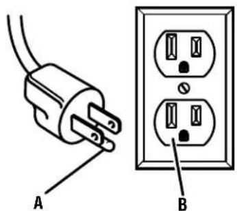
Fig.1
WRONG MAL INCORRECTO
Fig. 18
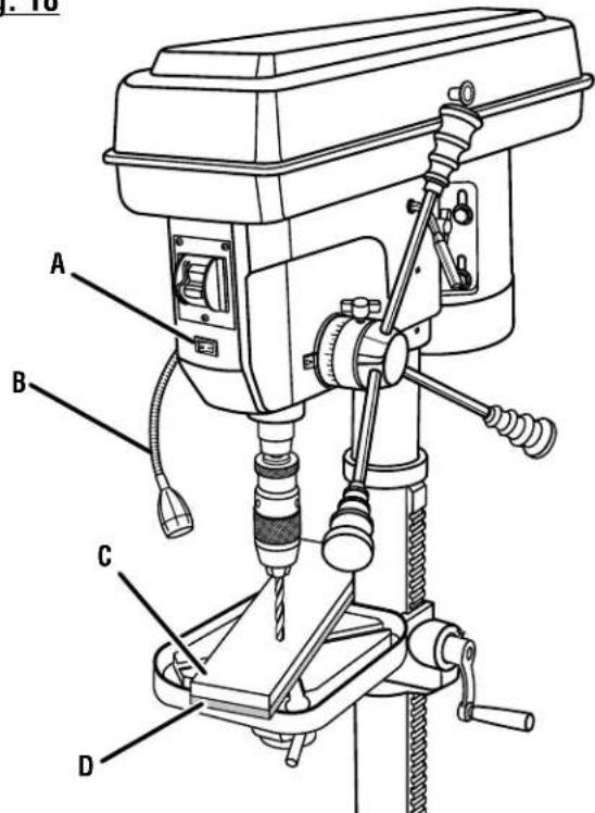
A - Worklight on/off switch (commutateur marche/arrêt du lampe, interruptor de encendido/apagado de la luz)
B-Worklight (lampe, luz de trabajo)
C - Workpiece (piece, pieza de trabajo)
D-Backup material (matériel d'appui, material de respaldo)
Customer Service Information:
For parts or service, do not return this product to the store. Contact your nearest RIDGID® authorized service center. Be sure to provide all relevant information when you call or visit. For the location of the authorized service center nearest you, please call 1-866-539-1710 or visit us online at www.RIDGID.com.
MODEL NO. SERIAL NO.
RIDGID is a registered trademark of RIDGID, Inc., used under license.


- WARNING:
- TABLE DES MATIÈRES
- READ ALL INSTRUCTIONS
- EXTENSION CORDS
- ELECTRICAL CONNECTION
- SPEED AND WIRING
- GROUNDING INSTRUCTIONS
- PRODUCT SPECIFICATIONS
- KNOW YOUR DRILL PRESS
- BASE
- BELT GUARD
- BELT TENSION HANDLE
- BELT TENSION LOCK
- BEVEL SCALE
- CHUCK
- COLLAR
- COLUMN SUPPORT
- DEPTH SCALE
- DEPTH SCALE LOCK
- FEED HANDLE
- RACK
- SWITCH ASSEMBLY
- TABLE
- TABLE BEVEL LOCK
- TABLE SUPPORT LOCK
- WORKLIGHT
- UNPACKING
- TOOLS NEEDED
- LOOSE PARTS LIST
- INSTALLING THE COLUMN TO THE BASE
- INSTALLING THE TABLE CRANK AND GEAR RACK
- INSTALLING THE TABLE
- INSTALLING THE HEAD ASSEMBLY
- TENSIONING THE BELTS
- INSTALLING THE FEED HANDLES
- INSTALLING THE CHUCK
- SQUARING THE TABLE TO HEAD
- OPERATION
- To turn your saw on:
- To turn your saw off:
- To lock your saw:
- INSTALLING/REMOVING BITS
- To install bits:
- To remove bits:
- USING THE WORKLIGHT
- POSITIONING TABLE AND WORKPIECE
- MARKING HOLE LOCATION
- DRILLING
- DRILLING TO A SPECIFIC DEPTH
- DRILLING USING THE DEPTH SCALE
- TO LOCK CHUCK AT DESIRED DEPTH
- TILTING TABLE
- To use the table in a bevel (tilted) position:
- To return table to original position:
- ADJUSTMENTS
- ADJUSTING TABLE HEIGHT
- CHANGING SPEEDS
- ADJUSTING QUILL RETURN SPRING
- GENERAL
- LUBRICATION
- PULLEYS
- REMOVING CHUCK
- TROUBLESHOOTING
- RIDGID® HAND HELD AND STATIONARY POWER TOOL
- YEAR LIMITED SERVICE WARRANTY
- 90-DAY SATISFACTION GUARANTEE POLICY
- WHAT IS COVERED UNDER THE 3 YEAR LIMITED SERVICE WARRANTY
- HOW TO OBTAIN SERVICE
- WHAT IS NOT COVERED
- ADDITIONAL LIMITATIONS
- TERTISSEMENT :
- RÉPARATIONS SOUS GARANTIE
- ADVERTENCIA:
- INSTALAR EL LA COLUMNA A LA BASE
- Customer Service Information:
Brand : RIDGID
Model : R1500
Category : Drill