600-I - Drill RIDGID - Free user manual and instructions
Find the device manual for free 600-I RIDGID in PDF.

| Product Type | Electric Pipe Threader |
| Brand and Model | RIDGID 600-I |
| Compatible Pipe Diameter | 1/8 to 1¼ inches (3 to 32 mm) |
| Motor | Universal single-phase, 1270 W (120 V) / 1020 W (220-240 V) |
| Voltage and Current | 120 V / 12 A or 220-240 V / 5 A |
| Speed | 36 rpm (120 V) / 32 rpm (220-240 V) |
| Double Insulation | Yes |
| Rotation Reverser | Yes, slide switch for right or left threading |
| Switch | Two-stage trigger with momentary contact |
| Dimensions (L × W × H) | 508 × 95 × 191 mm (20 × 3.75 × 7.5 inches) |
| Weight | 5.7 kg (12.65 lb) |
| Sound Pressure Level | 83 dB(A) (K=3) |
| Sound Power Level | 94 dB(A) (K=3) |
| Vibrations | < 2.5 m/s² (K=1.5) |
| Die Head Type | RIDGID 11-R ratcheting die head |
| System Support | Type 601 or 602 (supplied) |
| Standard Equipment | Drive system, support, instruction manual |
| Routine Maintenance | Chip cleaning, motor brush inspection (every 6 months), die replacement |
| Safety | Wear safety glasses, no gloves, mandatory use of support |
| Warranty | Full Lifetime Warranty |
| Approvals | CE compliant, double insulation |
Frequently Asked Questions - 600-I RIDGID
User questions about 600-I RIDGID
0 question about this device. Answer the ones you know or ask your own.
Ask a new question about this device
Download the instructions for your Drill in PDF format for free! Find your manual 600-I - RIDGID and take your electronic device back in hand. On this page are published all the documents necessary for the use of your device. 600-I by RIDGID.
USER MANUAL 600-I RIDGID
Recording Form for Machine Serial Number 1
Safety Symbols 2
General Power Tool SafetyWarnings
Work Area Safety. 2
Electrical Safety 2
Personal Safety 3
Power Tool Use and Care 3
Service 3
Specific Safety Information
Power Drive Safety 4
Description, Specifications and Standard Equipment
Description 4
Specifications 5
Standard Equipment 5
Pre-Operation Inspection 6
Set-Up and Operation 7
7
Resisting Threading Forces 8
Threading 9
Inspecting Threads 10
Maintenance Instructions
Cleaning. 11
Changing Dies in 11-R Die Heads 11
ReplacingBrushes in Motor 11
Accessories 11-12
Machine Storage 12
Service and Repair 12
Threading Oil 12
Disposal 12
Troubleshooting 13
EC Declaration of Conformity . Inside Back Cover
Lifetime Warranty . Back Cover
*Original Instructions - English
Power Drives
600-I/690-I


WARNING!
Read this Operator's Manual carefully before using this tool. Failure to understand and follow the contents of this manual may result in electrical shock, fire and/or serious personal injury.
| 600-1/690-1 Power Drives | |
| Record Serial Number below and retain product serial number which is located on nameplate. | |
| Serial No. | |
Safety Symbols
In this operator's manual and on the product, safety symbols and signal words are used to communicate important safety information. This section is provided to improve understanding of these signal words and symbols.

This is the safety alert symbol. It is used to alert you to potential personal injury hazards. Obey all safety messages that follow this symbol to avoid possible injury or death.

DANGER
DANGER indicates a hazardous situation which, if not avoided, will result in death or serious injury.

WARNING
WARNING indicates a hazardous situation which, if not avoided, could result in death or serious injury.

CAUTION
CAUTION indicates a hazardous situation which, if not avoided, could result in minor or moderate injury.
NOTICE
NOTICE indicates information that relates to the protection of property.

This symbol means read the operator's manual carefully before using the equipment. The operator's manual contains important information on the safe and proper operation of the equipment.

This symbol means always wear safety glasses with side shields or goggles when handling or using this equipment to reduce the risk of eye injury.

This symbol indicates the risk of fingers, hands, clothes and other objects catching on or between gears or other rotating parts and causing crushing injuries.

This symbol indicates the risk of electrical shock.

This symbol indicates the risk of machine tipping, causing striking or crushing injuries.

This symbol means do not wear gloves while operating this machine to reduce the risk of entanglement.

This symbol means use support device to resist the threading forces, improve control, and reduce the risk of striking, crushing, and/or other injuries.
General Power Tool Safety Warnings*
WARNING
Read all safety warnings, instructions, illustrations and specifications provided with this power tool. Failure to follow all instructions listed below may result in electric shock, fire and/or serious injury.
SAVE ALL WARNING AND INSTRUCTIONS FOR FUTURE REFERENCE!
The term "power tool" in the warnings refers to your mains-operated (corded) power tool or battery-operated (cordless) power tool.
Work Area Safety
- Keep your work area clean and well lit. Cluttered or dark areas invite accidents.
-
Do not operate power tools in explosive atmospheres, such as in the presence of flam mable liquids, gases, or dust. Power tools create sparks which may ignite the dust or fumes.
-
Keep children and bystanders away while operating a power tool. Distractions can cause you to lose control.
Electrical Safety
- Power tool plugs must match the outlet. Never modify the plug in any way. Do not use any adapter plugs with earthed (grounded) power tools. Un modified plugs and matching outlets will reduce risk of electric shock.
- Avoid body contact with earthed or grounded surfaces such as pipes, radiators, ranges and refrigerators. There is an increased risk of electrical shock if your body is earthed or grounded.
- Do not expose power tools to rain or wet conditions. Water entering a power tool will increase the risk of electrical shock.
- Do not abuse the cord. Never use the cord for carrying, pulling or unplugging the power tool. Keep cord away from heat, oil, sharp edges or
moving parts. Damaged or entangled cords increase the risk of electric shock.
- When operating a power tool outdoors, use an extension cord suitable for outdoor use. Use of a cord suitable for outdoor use reduces the risk of electric shock.
- If operating a power tool in a damp location is unavoidable, use a Ground Fault Circuit Interruptions (GFCI) protected supply. Use of a GFCI reduces the risk of electric shock.
Australia: If operating a power tool in a damp location is unavoidable, use a Residual Current Device (RCD) protected supply. Use of a RCD reduces the risk of electric shock.
Australia: It is recommended that the tool always be supplied via a Residual Current Device having a residual current of 30mA or less.
Personal Safety
- Stay alert, watch what you are doing and use common sense when operating a power tool. Do not use a power tool while you are tired or under the influence of drugs, alcohol, or medication. A moment of inattention while operating power tools may result in serious personal injury.
- Use personal protective equipment. Always wear eye protection. Protective equipment such as dust mask, non-skid safety shoes, hard hat, or hearing protection used for appropriate conditions will reduce personal injuries.
- Prevent unintentional starting. Ensure the switch is in the OFF-position before connecting to power source and/or battery pack, picking up or carrying the tool. Carrying power tools with your finger on the switch or energizing power tools that have the switch ON invites accidents.
- Remove any adjusting key or wrench before turning the power tool ON. A wrench or a key left attached to a rotating part of the power tool may result in personal injury.
- Do not overreach. Keep proper footing and balance at all times. This enables better control of the power tool in unexpected situations.
- Dress properly. Do not wear loose clothing or jewel ry. Keep your hair and clothing away from moving parts. Loose clothes, jewelry, or long hair can be caught in moving parts.
- If devices are provided for the connection of dust extraction and collection facilities, ensure these are
connected and properly used. Use of dust collection can reduce dust-related hazards.
- Do not let familiarity gained from frequent use of tools allow you to become complacent and ignore tool safety principles. A careless action can cause severe injury within a fraction of a second.
Power Tool Use and Care
- Do not force the power tool. Use the correct power tool for your application. The correct power tool will do the job better and safer at the rate for which it is designed.
- Do not use power tool if the switch does not turn it ON and OFF. Any power tool that cannot be controlled with the switch is dangerous and must be repaired.
- Disconnect the plug from the power source and/or remove the battery pack, if detachable, from the power tool before making any adjustments, changing accessories, or storing power tools. Such preventive safety measures reduce the risk of starting the power tool accidentally.
- Store idle power tools out of the reach of children and do not allow persons unfamiliar with the power tool or these instructions to operate the power tool. Power tools are dangerous in the hands of untrained users.
- Maintain power tools and accessories. Check for misalignment or binding of moving parts, breakage of parts and any other condition that may affect the power tool's operation. If damaged, have the power tool repaired before use. Many accidents are caused by poorly maintained power tools.
- Keep cutting tools sharp and clean. Properly maintained cutting tools with sharp cutting edges are less likely to bind and are easier to control.
- Use the power tool, accessories and tool bits etc. in accordance with these instructions, taking into account the working conditions and the work to be performed. Use of the power tool for operations different from those intended could result in a hazardous situation.
- Keep handles and grasping surfaces dry, clean and free from oil and grease. Slippery handles and grasping surfaces do not allow for safe handling and control of the tool in unexpected situations.
Service
- Have your power tool serviced by a qualified repair
person using only identical replacement parts. This will ensure that the safety of the power tool is maintained.
Specific Safety Information
WARNING
This section contains important safety information that is specific to this tool.
Read these precautions carefully before using the power drives to reduce the risk of electrical shock or serious personal injury.
SAVE THESE INSTRUCTIONS!
Keep this manual with the machine for use by the operator.
Power Drive Safety
Always use the support device provided with the tool. Loss of control during operation can result in personal injury.
- Keep sleeves and jackets buttoned while operating the tool. Do not reach across the tool or pipe. Clothing can be caught by the pipe or the tool resulting in entanglement.
- Only one person must control the work process and tool operation. Additional people involved in the process may result in unintended operation and personal injury.
- Keep floors dry and free of slippery materials such as oil. Slippery floors invite accidents.
- Do not wear gloves while operating the tool. Do not reach across the tool or pipe. Gloves can be caught by the pipe or the tool resulting in entanglement.
- Always firmly hold the power drive when threading or backing die head off the pipe to resist threading forces, regardless of support device use. This will reduce the risk of striking, crushing and other injuries.
- Follow instructions on proper use of this machine. Do not use for other purposes such as drilling holes or turning winches. Other uses or modifying this machine for other applications may increase the risk of serious injury.
- Do not use this power drive if ON/OFF switch is broken. This switch is a safety device that lets you shut off the motor by releasing the switch.
- Do not use dull or damaged dies. Sharp cutting
tools require less torque and the power drive is easier to control.
- Keep handles dry and clean; free from oil and grease. Allows for better control of tool.
- Only use RIDGID die heads with RIDGID Power Drives. Other die heads may not fit correctly in the power drive increasing the risk of equipment damage and personal injury.
If you have any question concerning this RIDG product:
- Contact your local RIDGID distributor.
- Visit RIDGID.com to find your local RIDGID contact point.
- Contact Ridge Tool Technical Service Department at rtctechservices@emerson.com, or in the U.S. and Canada call (800) 519-3456.
Description, Specifications and Standard Equipment
Description
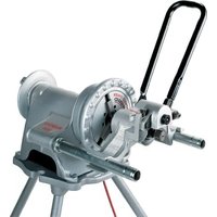
The RIDGID Model 600-I and 690-I Power Drives are double insulated drives that provide power for threading pipe and conduit. Forward and Reverse rotation can be selected with a slide switch while ON/OFF is controlled by a two-step momentary contact switch.
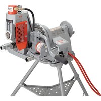
The 600-I Power Drive is designed to use RIDGID 11-R Drop Head Die Heads (18'' - 114'' pipe). The 690-I Power Drive is designed to use RIDGID 11-R Drop Head Die Heads (18'' - 2'' pipe). An adapter is required for use of the 690-I Power Drive with the 1/8'' - 114'' sizes. The adapter and the 112'' - 2'' sizes are held in the 690-I Power Drive using a Retaining Mechanism.

Figure 1 - Model 600-I Power Drive

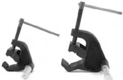
Figure 2 - Model 690-I Power Drive
Figure 3-602/692 Support Arms
600-I Power Drive and 690-I Power Drive machine serial number plate is located on the bottom of motor housing. The last 4 digits of the serial number indicate the month and year of the manufacture (MMYY).

Figure 4 - Machine Serial Number
Standard Equipment
The Model 600-I/690-I Power Drives come with the following items:
Power Drive
- 690-1 Adapter (690-1 only)
Operator's Manual
NOTICE Selection of appropriate materials and installation, joining and forming methods is the responsibility of the system designer and/or installer. Selection of improper materials and methods could cause system failure.
Stainless steel and other corrosion resistant materials can be contaminated during installation, joining and form
Specifications
| Parameter 600-I Power Drive | 690-I Power Drive | |
| Pipe Threading Capacity | 1/8 to 1¼ inch(3 to 32 mm) (3 to 50 mm) | 1/8 to 2 inch |
| Die Head Holding Ring Spring | Retaining Mechanism (1 | 1/2 - 2 inch)Ring Spring (1/8 - 1¼ inch) |
| LH Threads Yes Yes | ||
| Support Arm No. 602, No. 601 | No. 692, No. 691 | |
| Adapter Not Required. Used with | 1/8" through 1¼" Die Heads. | |
| Motor Type Universal Motor, Single Phase | Universal Motor, Single Phase | |
| Watts | 1270 (120V), 1020 (220-240V) | 1270 (120V), 1020 (220-240V) |
| Voltage/Phase Available | 120V/1PH, 220-240V/1PH | 120V/1PH, 220-240V/1PH |
| Amps | 12A (120V), 5A (220-240V) | 12A (120V), 5A (220-240V) |
| Operating Speed (RPM) | 36 (120V), 32 (220-240V) | 36 (120V), 32 (220-240V) |
| Controls | Forward/Reverse Slide SwitchON/OFF two-step momentary contact switch | Forward/Reverse Slide SwitchON/OFF two-step momentary contact switch |
| Gear Head Die Cast Aluminum | Permanently Greased Die Cast Aluminum | Permanently Greased |
| Length | 20 inch (508 mm) | 24.13 inch (613 mm) |
| Width | 3.75 inch (95 mm) | 4.75 inch (121 mm) |
| Height | 7.5 inch (191 mm) | 8 inch (203 mm) |
| Weight | 12.65 lbs (5.7 kg) | 21.15 lbs (9.6 kg) |
| Sound Pressure (Lpa)* | 83 dB(A), K=3 | 83 dB(A), K=3 |
| Sound Power (Lwa)* | 94 dB(A), K=3 | 94 dB(A), K=3 |
| Vibration* | < 2.5 m/s², K=1.5 | < 2.5 m/s², K=1.5 |
Sound and Vibration measurements are measured in accordance with a standardized test per Standard IEC62841-1.
Vibration levels may be used for comparison with other tools and for preliminary assessment of exposure.
Sound and vibration emissions may vary due to your location and specific use of these tools.
- Daily exposure levels for sound and vibration need to be evaluated for each application and appropriate safety measures taken when needed. Evaluation of exposure levels should consider the time a tool is switched off and not in use. This may significantly reduce the exposure level over the total working period.
ing. This contamination could cause corrosion and premature failure. Careful evaluation of materials and methods for the specific service conditions, including chemical and temperature, should be completed before any installation is attempted.
Pre-Operation Inspection
WARNING


Before each use, inspect power drive and correct any problems to reduce the risk of serious injury from electric shock, crushing injuries and other causes and prevent power drive damage.
- Make sure that the power drive is unplugged.
- Clean any oil, grease or dirt from the power drive and support device, including the handles and controls. This aids inspection and helps prevent the machine or control from slipping from your grip.
-
Inspect the power drive and support arm for the following:
-
Damage or modification to the cord and plug.
- Proper assembly, maintenance and completeness.
- Damaged, misaligned or binding parts.
- Proper operation of two-step momentary contact ON/OFF switch (Figure 5).
- Support arm gripping teeth are clean and in good condition. Teeth can be cleaned with a wire brush.
- Presence and readability of the warning label.
- Any other condition which may prevent safe and normal operation.
If any problems are found, do not use the power drive or support device until the problems have been repaired.

Figure 5A - Two Step Momentary Contact ON/OFF Switch
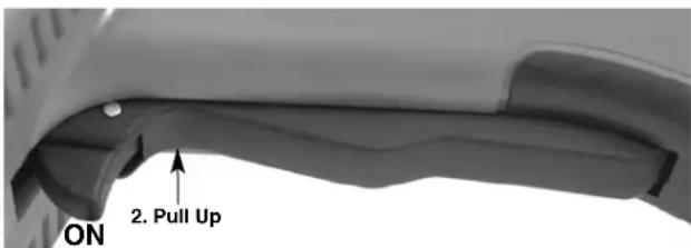
Figure 5B - Two Step Momentary Contact ON/OFF Switch
- Inspect the cutting edges of the dies for wear, deformation, chips or other issues. Dull or damaged cutting tools increase the amount of force required, produce poor quality threads and increase the risk of injury.
- Inspect and maintain any other equipment being used per its instructions to make sure it is functioning properly.
-
Following the Set Up and Operation instructions, check the power drive for proper operation.
-
Move the F/R (Forward/Reverse) switch to the F position. Depress and release the ON/OFF switch (Figure 5). Confirm that the power drive rotates in the clockwise direction (see Figure 6) and stops when releasing the switch.
- Repeat the process for the REVERSE (counterclockwise) operation. If the power drive does not rotate in the correct direction, or the ON/OFF switch does not control the machine operation, do not use the machine until it has been repaired.
NOTICE Change position of the F/R slide switch only when the ON/OFF trigger switch is released. Allow the power drive to come to a complete stop before reversing the direction with the F/R slide switch. This will reduce the risk of power drive damage.
- Depress and hold the ON/OFF switch. Inspect the moving parts for misalignment, binding, odd noises or any other unusual conditions. Release the ON/OFF switch. If any unusual conditions are found, do not use the machine until it has been repaired.

Figure 6A - F (FORWARD) (Clockwise) Switch Position

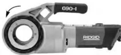
Figure 6B - R (REVERSE) (Counter-Clockwise) Switch Position
- Release the ON/OFF switch and with dry hands unplug the machine.
Set-Up and Operation
WARNING


Set up and operate the power drive according to these procedures to reduce the risk of injury from electric shock, entanglement, striking, crushing and other causes, and to help prevent power drive damage.
Use an appropriate support device per these instructions. Sup port devices im prove control and reduce the risk of striking, crushing, and/or other injuries.
When using a support device other than the supplied support arm, the support device must react against the gear housing or fan housing. Support devices contacting the motor housing or handle may damage these parts or increase the risk of injury.
Always firmly hold the power drive when threading or backing die head off the pipe to resist use forces, regardless of support device use. This will reduce the risk of striking, crushing and other injuries.
Do not wear gloves or loose clothing. Keep sleeves and jackets buttoned. Loose clothing can become entangled in rotating parts and cause crushing and striking injuries.
Properly support pipe. This will reduce the risk of falling pipe, tipping and serious injury.
Do not use a power drive without a properly operating ON/OFF switch and F/R slide switch.
One person must control both the work process and the ON/OFF switch. Do not operate with more than one person. In case of entanglement, the operator must be in control of the ON/OFF switch.
-
Check work area for:
-
Adequate lighting.
-
Flammable liquids, vapors or dust that may ignite. If present, do not work in area until sources have been identified and corrected. The power drives are not explosion proof and can cause sparks.
-
Clear, level, stable, dry location for all equipment and operator.
Good ventilation. Do not use extensively in small, enclosed areas. - Properly wired electrical outlet of the correct voltage. If in doubt, have outlet inspected by a licensed electrician.
-
Clear path to electrical outlet that does not contain any potential sources of damage for the power cord.
-
Inspect the pipe to be threaded and associated fittings and confirm that the selected power drive is a correct tool for the job. See Specifications. Do not use to thread anything other than straight stock.
Equipment for other applications can be found in the Ridge Tool catalog, online at RIDGID.com or by calling Ridge Tool Technical Service in the U.S. and Canada at (800) 519-3456. - Make sure equipment to be used has been properly inspected.
- Properly prepare the pipe as needed. Make sure the pipe is squarely cut and deburred. Pipe cut at an angle can damage the dies while threading or cause difficulty engaging the die head.
Installing Die Heads
- Installing 1 12 or 2" Die Head or Adapter in 690-I:
a. Make sure ON/OFF switch is released and power drive is unplugged.
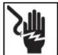
b. Rotate the drive ring counter-clockwise to open the retaining mechanism. Fully insert the die head or adapter (if required) spline end into the power drive (Figure 7).
c. Release the drive ring and confirm that the die head/adapter is secure.
d. Reverse process to remove.
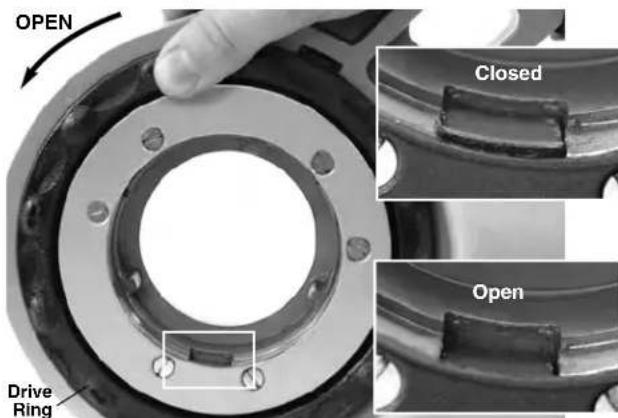
Figure 7 - Retaining Mechanism, Drive Ring in the Open/Closed Position
Figure 8 - Installing Adapter Into 690-I
- Installing 1^1/4 and smaller Die Heads:
a. Make sure the ON/OFF switch is released and power drive unplugged from the outlet.
b. If needed install the adapter in the 690-I (Figure 8).
c. Squarely insert the octagonal end of the 11-R Die Head into the power drive until secured by the spring ring. On the 600-I, the die head can be inserted into either side of the power drive. With the 690-I, die heads can only be inserted from the adapter side.
d. To remove, pull die head from power drive. If needed, use a soft face hammer or a block of wood to tap the die head out. Do not pound on the die head, this can damage the tool.
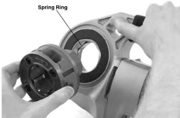
Figure 9 - Installing Die Heads into 600-I Power Drive
- Position the power drive F/R Slide Switch for the desired right or left hand thread. See Figure 10.
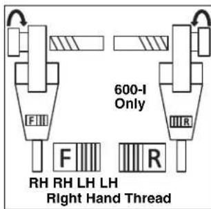
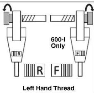
Figure 10 - Slide Switch/Die Head Orientation
- Make sure that pipe to be threaded is stable and secured to prevent tipping during use. Use appropriate pipe stands to support pipe length.
- Check the level of RIDGID Thread Cutting Oil in the RIDGID 418 oiler. Remove the chip tray and confirm that the filter screen is clean and fully submerged in oil. Replace or add oil if necessary. Place the 418 Oiler bucket under the pipe end to be threaded.
Resisting Threading Forces
Using the supplied support arm:
a. Always use the supplied support arm (601 or 602 support arm for 600-I, 691 or 692 support arm for 690-I) unless it can't be used because of space or other constraints. The support arm clamps to the pipe and helps to resist the threading forces.
b. Position the support arm on pipe, so end of support arm aligns with end of pipe and top of support arm is horizontal (Figure 11). This properly places the support arm for threading and prevents threading oil from entering the motor (Figure 12).
c. Make sure that the support arm jaws are squarely aligned with the pipe and securely tighten the support arm.
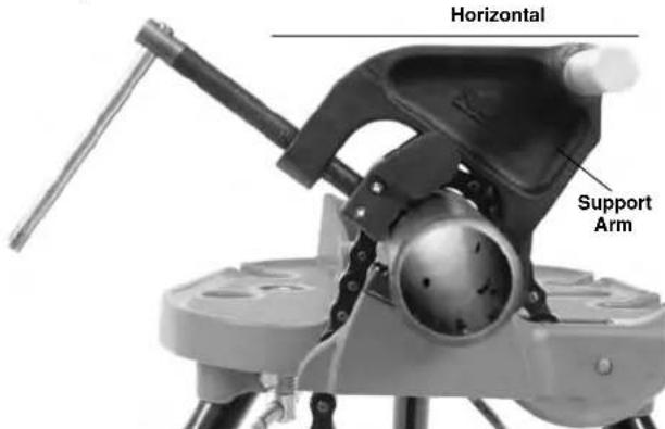
Figure 11A - Positioning the Support Arm
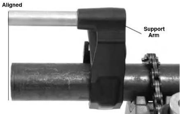
Figure 11B - Positioning the Support Arm

Figure 12 - Proper Orientation of the Power Drive
When support arm can't be used:
When threading pipe in place or similar application, the support arm may not be able to be used because of space constraints.
a. If possible remove the pipe and thread in a vise. If this cannot be done, other support devices must be used to help resist threading forces, such as placing the power drive gear or fan housing against an adjacent structural member (examples include walls, beams and joists). This requires that the pipe and surroundings be able to withstand the weight of the tool and the threading forces. It may be necessary to add temporary or permanent pipe supports or structural elements.
b. For right hand threads, die head will rotate clockwise (looking at the face of the Die Head). Forces developed by the threading torque will be in the opposite or counter-clockwise direction. Rotation and force will be reversed for left hand threads. Make sure that the support device is set up to properly absorb the threading force.
c. Do not place the power drive motor or handle against adjacent structural members to react threading forces, as this may cause power drive damage.
d. Keep power drive against the structural member and do not place fingers or hands between the power drive and the structural member. When backing die head off thread, always firmly hold the power drive to resist forces from breaking the thread chips. These steps will reduce the risk of striking, crushing and other injuries. The ON/OFF switch can be released at any time to shut OFF the power drive.
Always firmly hold the power drive when threading or backing die head off pipe to resist forces, regardless of support device use. This will reduce the risk of striking, crushing and other injuries. The ON/OFF switch can be released at any time to shut off the power drive.
Threading
- With dry hands, plug in the power drive.
- Position the die head over the pipe end and support the power drive as directed in the Resisting Threading Forces Section.
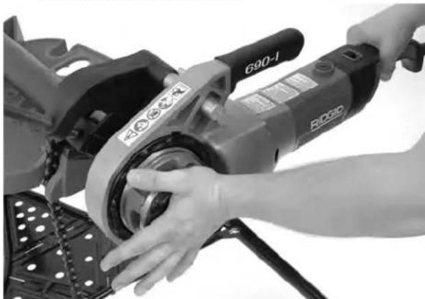
Figure 13 - Starting the Thread
- Simultaneously actuate the ON/OFF switch and push against the Die Head cover plate with the palm of free hand to start the thread. Do not wear gloves, jewelry or use a rag while pushing on the cover plate - this increases the risk of entanglement and injury. Once the dies engage the pipe, threads will be cut as the dies pull themselves onto the end of the pipe.
Always firmly hold the power drive handle to resist the handle forces. Support devices can slip and allow the
power drive to move. The ON/OFF switch can be released at any time to shut off the power drive.
- Stop pushing on cover plate and use oiler to apply a generous quantity of RIDGID Thread Cutting Oil to the area being threaded. This will lower threading torque, improve thread quality and increase die life.
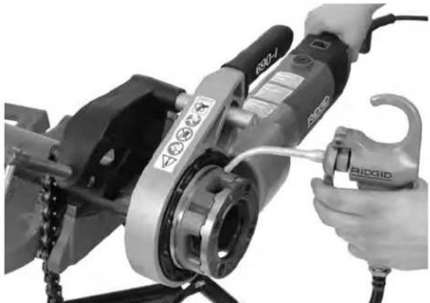
Figure 14 - Threading Pipe
- Depress ON/OFF switch until end of the pipe is even with edge of the dies and release the switch. Let the power drive come to a complete stop.
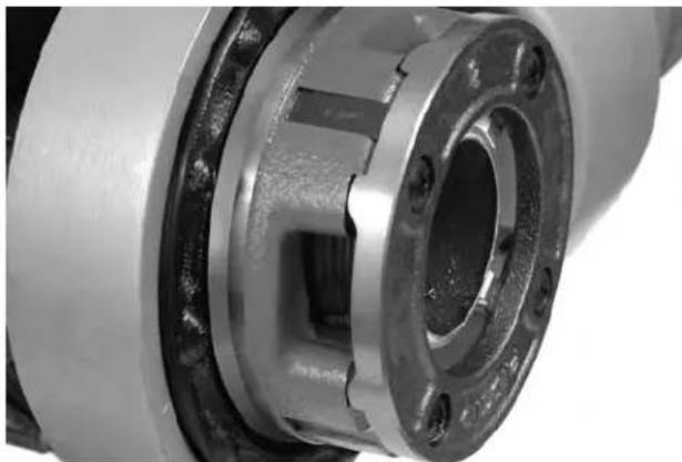
Figure 15 - Pipe Even with Edge of Dies
- Reverse the F/R slide switch and actuate the ON/OFF switch to remove Die Head from the threaded pipe. Hold onto the power drive handle firmly to resist the handle forces developed while backing off the Die Head.
NOTICE Change position of the F/R slide switch only when the ON/OFF switch is re leased. Allow the power drive to come to a complete stop before reversing the direction with the F/R slide switch. This will reduce the risk of power drive damage.
- Release the switch and remove the power drive and Die Head from the pipe.
- With dry hands unplug the power drive.
- Wipe oil and debris off the threads and out of the die head, taking care not to cut yourself on sharp debris or edges. Clean up any oil spills in the work area.
Inspecting Threads
- Remove any oil, chips or debris from the thread.
- Visually inspect thread. Threads should be smooth and complete, with good form. If issues such as thread tearing, thin threads, or pipe out-of-roundness are observed, the thread may not seal when made up. Refer to the "Troubleshooting" chart for help in diagnosing these issues.
-
Inspect the size of the thread. The preferred method of checking thread size is with a ring gauge. There are various styles of ring gauges, and their usage may differ from that shown in Figure 16.
-
Screw ring gauge onto the thread hand tight.
- Look at how far the pipe end extends through the ring gage. The end of the pipe should be flush with the side of the gauge plus or minus one turn. If thread does not gauge properly, cut off the thread, adjust the die head and cut another thread. Using a thread that does not gauge properly can cause leaks.
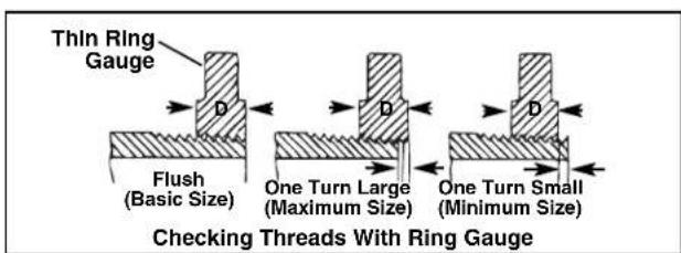
Figure 16 - Checking Thread Size
- If a ring gauge is not available to inspect thread size, it is possible to use a new clean fitting representative of those used on the job to gauge thread size. For 2^ and under NPT threads, the threads should be cut to obtain 4 to 5 turns to hand tight engagement with the fitting and for 2^ and under BSPT threads it should be 3 turns.
Maintenance Instructions
WARNING
Make sure that the ON/OFF switch is released and the machine is unplugged before performing any maintenance or making any adjustments.
Maintain tool according to these procedures to reduce the risk of injury from electrical shock, entanglement and other causes.
Cleaning
- After each use, empty the threading chips from the 418 Oiler chip tray and wipe out any oil residue.
- Wipe off any oil, grease, chips or dirt from the power drive, including the handles and controls. Clean the 690-I retaining mechanism.
- Wipe off any oil, grease or dirt from the support arm. If required, clean the support arm jaws with a wire brush.
- Remove chips and dirt from die heads.
Changing Dies in 11-R Die Heads
A variety of dies are available for installation in RIDGID
11-R Die Heads. See catalog for availability.
- Remove the four screws ④ from cover ② and remove the cover plate.
- Remove the old dies ③ from the die head.
- Insert new dies into slots - numbered edge up. Numbers on the dies must correspond with those on the die head slots. Always replace dies as a set.

Figure 17 - Installing Dies In Die Head
- Replace the cover plate and tighten the four screws lightly.
- Place die head on already threaded pipe until dies begin to thread. This forces stop on die outward
against lugs ④ on cover plate and properly sets the size.
- Tighten the four screws securely. Remove the threaded pipe and make a test cut.
Replacing Brushes in Motor
Check motor brushes every 6 months. Replace when worn to less than 5 / 16 (8 mm).
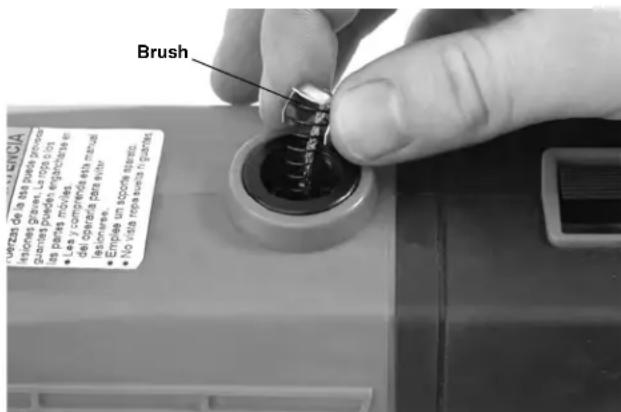
Figure 18 - Brush Installation
- Unplug the machine from power source.
- Unscrew brush caps (Figures 1 and 2). Remove and inspect brushes. Replace when worn to less than 5 / 16 (8 mm). Inspect the commutator for wear. If excessively worn, have tool serviced.
- Re-install brushes/install new brushes and securely tighten the brush caps.
- It is best practice to run the unit at idle for 15 minutes in the forward direction followed by 15 minutes in the reverse direction to seat the brushes to the commutator before use.
Accessories
WARNING
To reduce the risk of serious injury, only use accessories specifically designed and recommended for use with the 600-I and 690-I Power Drives such as those listed below. Other Accessories suitable for use with other tools may be hazardous when used with the 600-I and 690-I Power Drives.
600-I and 690-I Power Drive Accessories
| Catalog No. Description |
| 45923 602 Support Arm |
| 45928 692 Support Arm |
| 46668 600-I Carrying Case |
| 46673 690-I Carrying Case |
| 10883 418 Oiler with 1 Gallon Nu-Clear Oil |
| 16703 425 '1/8" - 2'1/2" TRISTAND Vise |
| 36273 460-6 '1/6" - 6" TRISTAND Vise |
Further information on accessories specific to the tool can be found in the RIDGID Catalog and online at RIDGID.com
Machine Storage
WARNING Power Drives must be kept indoors or well covered in rainy weather. Store the machine in a locked area that is out of reach of children and people unfamiliar with the machines. These machines can cause serious injury in the hands of untrained users.
Service and Repair
WARNING
Improper service or repair can make machine unsafe to operate.
The "Maintenance Instructions" will take care of most of the service needs of this machine. Any problems not addressed by this section should only be handled by an authorized RIDGID service technician.
Tool should be taken to a RIDGID Authorized Independent Service Center or returned to the factory.
For information on your nearest RIDGID Authorized Independent Service Center or any service or repair questions:
- Contact your local RIDGID® distributor.
- Visit RIDGID.com to find your local RIDGID contact point.
- Contact Ridge Tool Technical Service Department at rtctechservices@emerson.com or in the U.S. and Canada call (800) 519-3456.
Threading Oil
For information concerning RIDGID Thread Cutting Oil use and handling, refer to the labels on the container and Material Safety Data Sheet (MSDS). MSDS is available at RIDGID.com or by contacting Ridge Tool Technical Service Department at (800) 519-3456 in U.S. and Canada or rtctechservices@emerson.com.
Disposal
Parts of the Power Drives contain valuable materials and can be recycled. There are companies that specialize in recycling that may be found locally. Dispose of the components in compliance with all applicable regulations. Contact your local waste management authority for more information.

For EC Countries: Do not dispose of electrical equipment with household waste!
According to the European Guideline 2012/19/EU for Waste Electrical and Electronic Equipment and its implementation into national legislation, electrical equipment that is no
longer usable must be collected separately and disposed of in an environmentally correct manner.
Troubleshooting
| SYMPTOM POSSIBLE REASONS SOLUTION | ||
| Machine will not run. | Brushes do not touch armature. | Check brushes, replace if worn. |
| Machine not able to thread. | Dull dies. Overload due to torn or out-of-round threads. Poor quality or insufficient thread cutting oil. Insufficient line voltage. | Replace dies. See possible reasons below. Use RIDGID® Thread Cutting Oil in adequate quantity. Check power supply voltage. |
| Sparks forming at motor commutator. | Insufficient contact between brushes and commutator. Brushes do not touch commutator properly. Brushes of different manufacture. New brushes. | Tighten the brush caps to make sure brushes are pressed firmly onto commutator. Replace worn brushes and or armature. Only use RIDGID® brushes. Seat the brushes by running the unit at idle for 15 minutes in Forward and Reverse. |
| Die head does not start threading. | Die head not square with end of pipe. Engagement force not properly applied to the die head. Pipe end not squarely cut. Dull or broken dies. Machine running in wrong direction. Dies set improperly in the die head. | Push against die head cover plate to start thread. Apply engagement force through the center line of the pipe. Cut the pipe end squarely. Replace dies. Check position of the F/R Slide Switch. Ensure chasers are set outward against the cover plate lugs. |
| Torn threads. | Damaged, chipped or worn out dies. Improper or insufficient thread cutting oil. Incorrect type of die for material. Poor pipe material/quality. | Replace dies. Only use RIDGID® Thread Cutting Oil in adequate quantity. Select high-speed, stainless steel, or alloy dies that are suitable for the application. Use higher quality pipe. |
| Out-of-round or crushed threads. | Pipe wall thickness too thin. | Use schedule 40 or heavier wall thickness. |
| Support device turns while threading. | Support arm jaws dirty. Support arm not aligned properly. Support arm not tight. | Clean with wire brush. Align support arm squarely with the pipe. Tighten feedscrew. |
| Thin Threads. | Dies not placed in proper order. | Place dies in proper die head slot. |
CONSERVEZ CES INSTRUCTIONS!
Elyria, Ohio 44035-6001
U.S.A.
EC DECLARATION OF CONFORMITY
We declare that the machines listed above, when used in accordance with the operator's manual, meet the relevant requirements of the Directives and Standards listed below.
DECLARATION DE CONFORMITE CE
Ridge Tool Europe NV (RIDGID)
DEKLARACJA ZGODNOSCI WE
Mb3a8BnRE, YoHCTpyMeHTbI, NepeuNCHeBBbIe BIIwe, npy cYNOBmNcNoJIb3OBAHHG corlacho pyKoBOdCTBy nKcCnPyaTaUM, OTBeaHOT COOTBECTCYUOKIM TpeBaHHM Yka3aHHbIX HHXe DnEKeTbN CTAHAPTOB.
ES PREHLÁSENIE O ZHODE
Conforms to UL 62841-1/UL 62841-2-9
Certified to CSA C22.2#62841-1/CSA C22.2#62841-2-9

Signature:
Qualification: V.P. Engineering
Date: 04/01/2020
What is covered
RIDGID® tools are warranted to be free of defects in workmanship and material.
How long coverage lasts
This warranty lasts for the lifetime of the RIDGID tool. Warranty coverage ends when the product becomes unusable for reasons other than defects in workmanship or material.
How you can get service
To obtain the benefit of this warranty, deliver via prepaid transportation the complete product to RIDGE TOOL COMPANY, Elyria, Ohio, or any RIDGI/DAUTHORIZED INDEPENDENT SERVICE CENT. Pipe wrenches and other hand tools should be returned to the place of purchase.
What we will do to correct problems
Warranted products will be repaired or replaced, at RIDGE TOOL'S option, and returned at no charge; or, if after three attempts to repair or replace during the warranty period the product is still defective, you can elect to receive a full refund of your purchase price.
What is not covered
Failures due to misuse, abuse or normal wear and tear are not covered by this warranty. RIDGE TOOL shall not be responsible for any incidental or consequential damages.
How local law relates to the warranty
Some states do not allow the exclusion or limitation of incidental or consequential damages, so the above limitation or exclusion may not apply to you. This warranty gives you specific rights, and you may also have other rights, which vary, from state to state, province to province, or country to country.
No other express warranty applies
THIS FULL LIFETIME WARRANTY is the sole and exclusive warranty for RIDGID products. No employee, agent, dealer, or other person is authorized to alter this warranty or make any other warranty on behalf of the RIDGE TOOL COMPANY.
Ce qui est couvert?
Parts are available online at Store.RIDGID.com
Ridge Tool Company
400 Clark Street
Elyria, Ohio 44035-6001
U.S.A.