915 - Drill RIDGID - Free user manual and instructions
Find the device manual for free 915 RIDGID in PDF.

| Product Type | Manual Roll Groover |
| Brand | RIDGID |
| Model | 915 |
| Use | Manual grooving of steel, stainless steel, copper, PVC and aluminum pipes |
| Pipe Diameter (steel, stainless, PVC, aluminum) | 1 1/4 to 12 in (Schedule 10 and 40) |
| Copper Pipe Diameter | 2 to 8 in (types K, L, M, DWV) |
| Weight | 23 lb (approx. 10.4 kg) |
| Feed Mechanism | Feed screw with 1/2 in female square drive |
| Drive | Manual using a ratchet wrench (provided) |
| Depth Adjustment | Depth adjustment screw (graduations in turns) |
| Standard Roll Set (included) | For steel schedule 10 ∅ 2-6 in and schedule 40 ∅ 2-3 1/2 in |
| Compatible Accessories | Roll sets for steel 1 1/4-1 1/2 in, schedule 40 4-6 in, schedule 10 8-12 in, and copper 2-8 in; carrying case |
| Compliance | Grooves comply with AWWA C606-87 standard |
| Lubrication | Lithium grease via grease fittings |
| Routine Maintenance | Clean rolls, check wear, periodic lubrication |
| Safety | Safety glasses, fitted clothing, appropriate gloves, hard hat when overhead |
| Warranty | RIDGID Lifetime Warranty |
| After-Sales Service | RIDGID authorized service centers or return to factory |
Frequently Asked Questions - 915 RIDGID
User questions about 915 RIDGID
0 question about this device. Answer the ones you know or ask your own.
Ask a new question about this device
Download the instructions for your Drill in PDF format for free! Find your manual 915 - RIDGID and take your electronic device back in hand. On this page are published all the documents necessary for the use of your device. 915 by RIDGID.
USER MANUAL 915 RIDGID
Read this Operator's Manual carefully before using this tool. Failure to understand and follow the contents of this manual may result in serious personal injury.
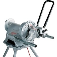
In Place Roll Groover
natural_image
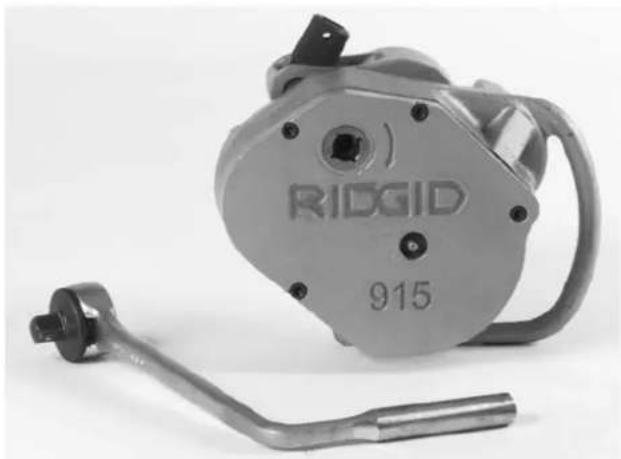
Ridgid industrial manual shaver with attached lever and handle (no visible text or symbols on the device itself)RIDGID®
Table of Contents
General Safety Information
Work Area Safety....2
Personal Safety 2
Tool Use and Care....2
Service....2
Specific Safety Information
Roll Groover Safety 2
Description, Specifications and Equipment
Description....3
Specifications....3
Standard Equipment 3
Accessories ....3
Roll Groover Inspection ....3
Roll Groover and Work Area Set-up....4
Operating 915 Roll Groover ....4
Pipe Preparation 4
915 Roll Groover Set-up 5
Adjusting for Groove Depth ....5
Forming the Groove....6
Dismounting the Roll Groover 7
Removing and Installing Groove Rolls ....7
Removing Roll Sets for the installation of Copper Roll Set....8
Installing Copper Roll Set 9
Accessories 10
Maintenance Instructions ....10
Tool Storage....10
Service and Repair......10
Standard Roll Groove Specifications....11
Pipe Maximum and Minimum Wall Thickness....12
Copper Roll Groove Specifications ....12
Trouble Shooting 13
Lifetime Warranty ....Back Cover
915
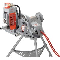
In Place Roll Groover
natural_image
Ridgid 915 manual hand crank assembly (no text or symbols on the device itself)General Safety Information
WARNING! Read and understand all instructions. Failure to follow all instructions listed below may result in serious personal injury.
SAVE THESE INSTRUCTIONS!
Work Area Safety
- Keep your work area clean and well lit. Cluttered benches and dark areas invite accidents.
- Keep bystanders, children, and visitors away while operating a tool. Distractions can cause you to lose control.
- Keep floors dry and free of slippery materials such as oil. Slippery floors invite accidents.
Personal Safety
- Stay alert, watch what you are doing and use common sense when operating a tool. Do not use tool while tired or under the influence of drugs, alcohol, or medications. A moment of inattention while operating tools may result in serious personal injury.
- Dress properly. Do not wear loose clothing or jewelry. Contain long hair. Keep your hair, clothing, and gloves away from moving parts. Loose clothes, jewelry, or long hair can be caught in moving parts.
- Do not overreach. Keep proper footing and balance at all times. Proper footing and balance enables better control of the tool in unexpected situations.
- Use safety equipment. Always wear eye protection. Dust mask, non-skid safety shoes, hard hat, or hearing protection must be used for appropriate conditions.
Tool Use and Care
- Do not force tool. Use the correct tool for your application. The correct tool will do the job better and safer at the rate for which it is designed.
- Store idle tools out of the reach of children and other untrained persons. Tools are dangerous in the hands of untrained users.
- Check for misalignment or binding of moving parts, breakage of parts, and any other condition that may affect the tool's operation. If damaged, have the tool serviced before using. Many accidents are caused by poorly maintained tools.
- Use only accessories that are recommended by the
manufacturer for your model. Accessories that may be suitable for one tool may become hazardous when used on another tool.
- Keep handles dry and clean; free from oil and grease. Allows for better control of the tool.
Service
- Tool service must be performed only by qualified repair personnel. Service or maintenance performed by unqualified repair personnel could result in injury.
- When servicing a tool, use only identical replacement parts. Follow instructions in the Maintenance Section of this manual. Use of unauthorized parts or failure to follow maintenance instructions may create a risk of injury.
Specific Safety Information
WARNING
Read this operator's manual carefully before using the 915 Roll Groover. Failure to understand and follow the contents of this manual may result in serious personal injury.
Call the Ridge Tool Company, Technical Service Department at (800) 519-3456 if you have any questions.
Roll Groover Safety
- Keep fingers away from rolls when grooving pipe. Keep Sleeves and jackets buttoned. They can become pinched resulting in serious injury.
- Do not wear loose fitting gloves. Can become caught in rolls resulting in serious injury.
- Handle pipe carefully and have all burrs removed from ends. Eliminates the risk of cuts to fingers and hands.
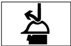
- When working overhead, all personnel should wear hard hats and be clear of the area below. Prevents serious injuries if roll groover or workpiece falls.
- Groover is designed to manually roll groove pipe and tubing. Other uses may result in injury.
- Do not use power activated devices to aid in rotating the groover. Using a tool in a manner not intended can result in injury.
SAVE THESE INSTRUCTIONS!
Description, Specifications and Equipment
Description
The RIDGID No. 915 Roll Groover is designed to manually form standard roll grooves on pipe or copper tube that is installed. The 915 is lightweight, only 23 lbs., and capable of grooving steel, stainless steel, PVC and aluminum pipe from 1^1/4 to 12^ and 2^ to 8^ copper tube (Type K, L, M, and DWV). The 1^1/2 hand ratchet rotates a feed screw that advances a groove roll into the pipe/tube to form a groove that meets specifications required for mechanical coupling systems, and also drives the 915 around the pipe.
CAUTION When properly used, the Model 915 Roll Groover makes grooves that are dimensionally within the specifications of AWWA C606-87. Selection of appropriate materials and joining methods is the responsibility of the system designer and/or installer. Before any installation is attempted, careful evaluation of the specific service environment, including chemical environment and service temperature, should be completed.
Specifications
Capacity ....Standard 2" – 6" Schedule 10 and 2" – 3 ^1/2 " Schedule 40 Steel Pipe
Depth Adjustment......Feed Screw with 12 " Female Drive
Actuation ......Feed Screw with ^1/2 " Ratchet Wrench
Weight.....23 lbs.
With Roll Changes:
- 2" – 8" Copper Tube, Type K, L, M, DWV
- 1^1/4 and 1^1/2 Schedule 10 and 40 Steel/Stainless Steel Pipe
- 4" – 6" Schedule 40 Steel/Stainless Steel Pipe
- 8" – 12" Schedule 10 Steel/Stainless Steel Pipe
(See Table II for Wall Thickness.)
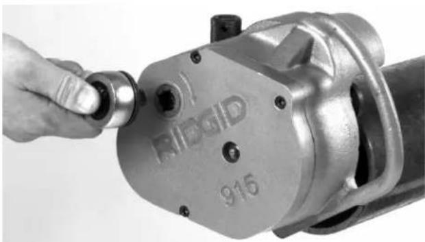
Standard Equipment
Model 915......Groove set for 2" – 6" Schedule 10 and 2" – 3 ^1/2 " Schedule 40 ^1/2 " Drive Ratchet w/button release
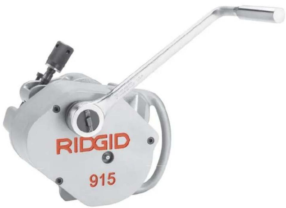
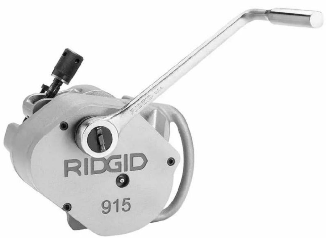
natural_image
Ridgid 915 electric motor with attached wrench and terminal block (no visible text or symbols on body)Figure 1 - 915 Roll Groover
Accessories
- Groove set for 1^1/4 to 1^1/2 Schedule 10 & 40 pipe.
- Groove set for 4" to 6" Schedule 40 pipe.
- Groove set for 8" – 12" Schedule 10.
- Copper groove set for 2" to 8" Copper Tube Type K, L, M, DWV.
- Carrying case for 915 and roll sets.
The 915 Roll Groover is a portable unit designed for occasional use on the jobsite and should not be used for high volume work.
Roll Groover Inspection
WARNING

To prevent serious injury, inspect your Roll Groover. The following inspection procedures should be performed on a daily basis:
- Inspect the Roll Groover for any broken, missing, misarranged or binding parts as well as any other conditions which may affect the safe and normal operation of this equipment. If any of these conditions are present, do not use the Roll Groover until any problem has been repaired.
-
Lubricate the Roll Groover if necessary according to the Maintenance Instructions.
-
Use groover rolls and accessories that are designed for your Roll Groover and meet the needs of your application. The correct groover tools and accessories allow you to do the job successfully and safely. Accessories designed for use with other equipment may be hazardous when used with this Roll Groover.
- Clean any oil, grease or dirt from all handles and controls. This reduces the risk of injury due to a tool or control slipping from your grip.
- Inspect the groove rolls to insure they are not damaged or worn. Worn groover rolls can lead to slippage and poor quality grooves.
Roll Groover and Work Area Set-Up
WARNING

natural_image
Simple black-and-white pictogram of a person pushing a block with an arrow, no text or symbols present.
natural_image
Silhouette of a person interacting with two gears (no text or symbols)To prevent serious injury, proper set-up of the Groover and work area is required. The following procedures should be fol- lowed to set-up the machine:
- Insure work area has adequate lighting.
- Clean up the work area prior to setting up any equipment. Always wipe up any oil that may be present.
- Check the groove and drive rolls to insure they are the correct size.
CAUTION Use of roll sets on both carbon and stainless steel pipe can lead to contamination of the stainless steel material. This contamination could cause corrosion and premature pipe failure. To prevent ferrous contamination, use roll sets dedicated for stainless steel grooving.
- Make sure pipe/tube is secured and not free to rotate prior to roll grooving.
- If pipe is not installed, use a bench vise or tristand vise to secure the pipe. Pipe supports must be used if pipe is greater than 36" in length.
⚠ WARNING Failure to properly support the pipe can result in the pipe falling.
Place vise and stands on a flat level surface. Be sure the pipe, vise and stands are stable.
- If the pipe/tube is installed, care must be taken to prevent pipe rotation or movement. Make sure that the added weight and force required of the 915 can be supported by the pipe hangers and clamps.
Operating the 915 Roll Groover
WARNING
natural_image
Simple black-and-white icon of a person with an arrow pointing left, no text or symbols present
natural_image
Silhouette of a person interacting with two gears (no text or symbols)Do not wear loose clothing when operating a Roll Groover. Keep sleeves and jackets buttoned.
Always wear eye protection to protect eyes from dirt and other foreign objects. When working overhead, wear a hard hat and keep personnel clear of area.
Keep hands away from grooving rolls. Do not wear loose fitting gloves when operating groovers. Use pipe stands to support pipe when using a pipe vise.
Unit to be hand driven only. Do not power with drill or other types of units.
Pipe Preparation
- Make sure pipe/tube end is cut square and free of burrs. Do not attempt to groove pipe that has been cut with a torch.
- Pipe/tube out-of-roundness must not exceed the total O.D. tolerances listed in the dimension specification (Table 1).
NOTE! Determine out-of-roundness by measuring maximum and minimum outside dimensions at 90 degree increments. Compare minimum and maximum numbers with pipe diameter column in Table 1.
- All internal or external weld beads, flash or seams must be ground flush at least 2" back from the pipe end.
IMPORTANT! Do not grind flats on the pipe outside wall where the coupling gasket seals (gasket seat area).
- The 915 Roll Groover will orbit around the pipe/tube. Care must be taken that adequate space is provided completely around material.
NOTE! The RIDGID 915 can roll groove pipe/tube within 3^1/2 of a wall, ceiling or any other obstruction.
915 Roll Groover Set-up
IMPORTANT! To confirm the proper groove depth, test grooves should be performed and checked with a Pi tape.
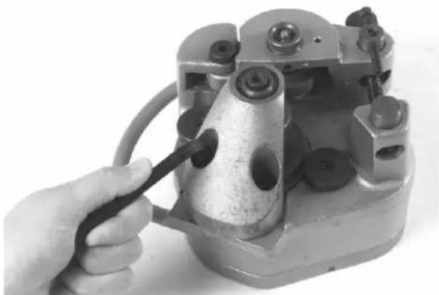
- At a bench or on the ground, rotate the feed screw counter clockwise to "open" the groove roll from the drive roll (Figure 2).
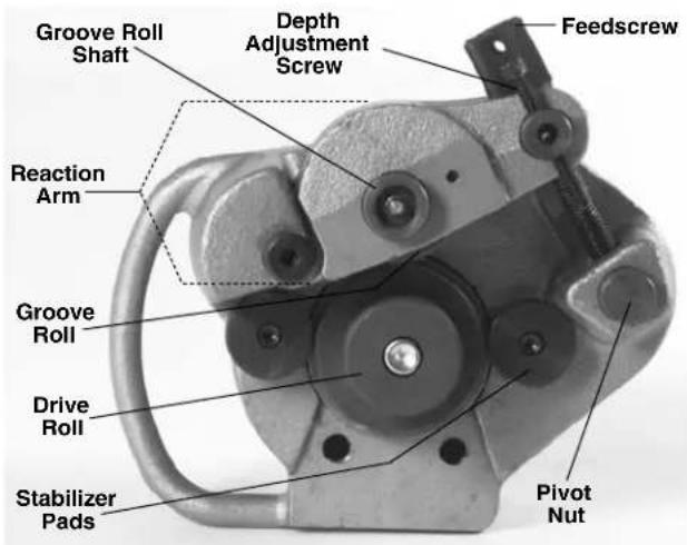
Figure 2 – “Open” Groove Roll from Drive Roll.
NOTE! Ensure that groove set specifications matches pipe/tube capacity to be grooved. See drive roll for capacity.
IMPORTANT! Do not attempt to groove copper tube with the steel groove set. Also do not attempt to groove steel with copper groove rolls.
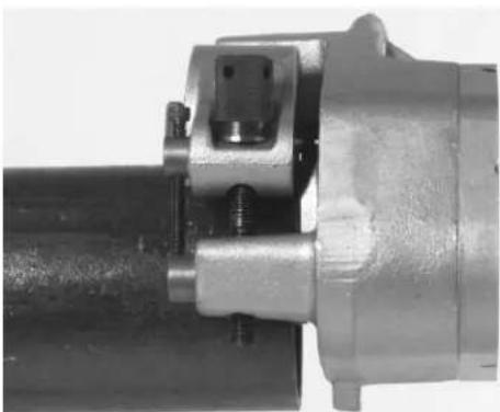
- Place 915 onto pipe/tube with feedscrew accessible (Figure 3).
natural_image
Close-up of a mechanical coupling or mounting bracket with metallic components and bolts (no visible text or symbols)Figure 3 – Placing Groover on Pipe
- Push 915 into pipe/tube until fully engaged. End of pipe should contact the drive roll flange (Figure 4).
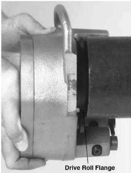
Figure 4 – Pipe Contact with Drive Roll Flange
- Rotate the feed screw clockwise by hand until tight. 915 should now be held in position on the pipe/tube.
Adjusting for Groove Depth
NOTE! The groove depth must be adjusted for each pipe/tube diameter and wall thickness.
-
With feedscrew handtight, run depth adjustment screw down until it touches the pivot nut.
-
Back the depth adjustment screw off the number of turns indicated in Chart 1 (For Steel/Stainless Steel, For Copper See Chart 2. These are approximate settings only).
NOTE! The distance between the depth adjustment screw and the pivot nut equals roll groove depth. Adjustments up or down, with test grooves, will ensure proper groove depths for couplings.
| Steel/Stainless Steel Pipe Diameter Turns | Sch. 10 Sch. 40 Turns | |
| 1^1/4 ′′ 3 | ^3/_4 | 4 |
| 1^1/2 ′′ 3 | ^3/_4 | 4 |
| 2′′ 3 | ^3/_4 | 4 |
| 2^1/2 ′′ 4 | ^3/_8 | 5^3/_8 |
| 3′′ 4 | ^3/_8 | 5^5/_8 |
| 4′′ 4 | ^5/_8 | 6^7/_8 |
| 6′′ 5 | 7 | ^1/_2 |
| 8′′ 6 | N | / |
| 10′′ 6 | ^1/_4 | N/A |
| 12′′ 7 | ^1/_2 | N/A |
Chart 1 – Depth Adjustment for Steel/Stainless Steel
| Cut Tube # of Screw TurnsSize K L M DWV | ||||
| 2" 2 2 1.75 N/A21/2" 2 2 1.75 N/A | ||||
| 3" | 2.25 | 2.25 | 2 | 2 |
| 4" | 3 | 2.75 | 2.75 | 2.5 |
| 5" | 4.25 | 3.75 | 3.5 | 3.25 |
| 6" | 4.75 | 4 | 3.75 | 3.25 |
| 8" | 6.5 | 4.75 | 4.25 | 3.5 |
Chart 2 – Depth Adjustment for Copper Tubing
NOTE! 1 turn depth setting screw = approximately .020" change in groove depth (.040 change in groove diameter).
Forming the Groove
- Place the ratchet into feedscrew (Figure 5).
natural_image
Close-up of a hand pouring liquid into a mechanical pipe fitting (no visible text or symbols)Figure 5 – Ratchet in Feedscrew
- Tighten feedscrew 1^1/2 turns. Be sure pipe is still flush with drive roll flange.
IMPORTANT! Extreme pressure caused by over ratcheting will cause distortion to thin wall pipe.
⚠ WARNING Do not use power actuated devices (drills, power drives, impact wrenches, etc.) to drive the 915 roll groover!
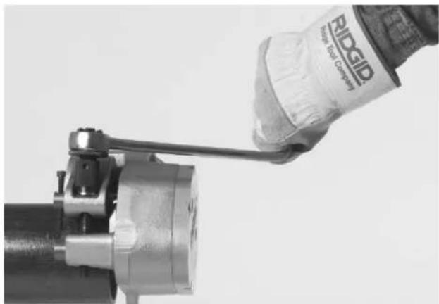
- Move ratchet from feedscrew to input drive. Turn ratchet to rotate 915 around pipe/tube one revolution (Figure 6).
natural_image
Close-up of a hand wearing an RIDGID Ridge Tool Company wristband, holding a mechanical clamp (no visible text or symbols on the device itself)Figure 6 - Grooving pipe
- Disconnect ratchet from input drive and place in feedscrew.
- Tighten feedscrew 12 turn.
CAUTION Under or over tightening the feed screw could result in the 915 "walking" off or slipping inside the pipe.
- Repeat steps 3 - 5 until depth adjustment screw touches the pivot nut.
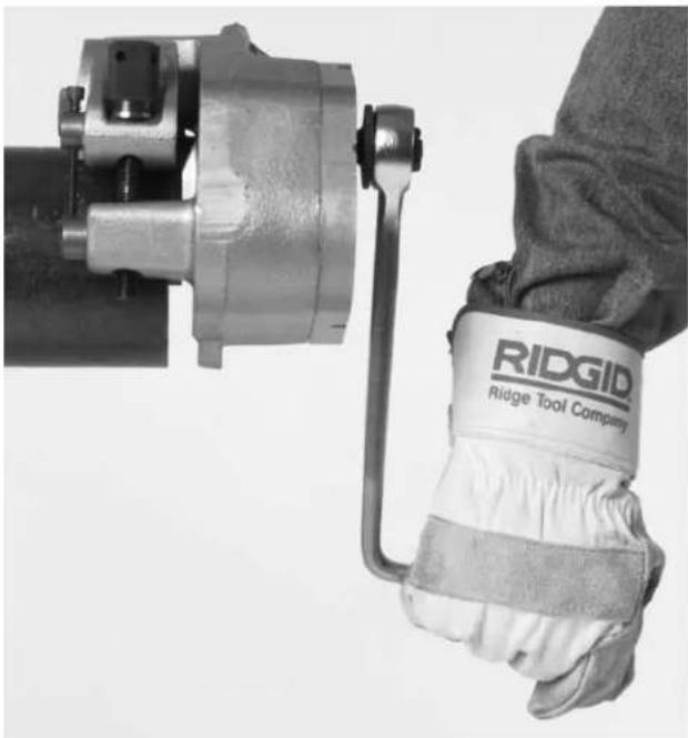
- Move ratchet from feedscrew to input drive (Figure 7). Turn ratchet to rotate 915 around pipe/tube two revolutions to complete groove and ensure uniformity.
natural_image
Close-up of a hand adjusting a metal mechanical component with a bolt, no visible text or symbolsFigure 7 - Ratchet in Input Drive
Dismounting the 915 Roll Groover
- After the roll grooving process is complete, insert the ratchet onto the feed screw and reverse the ratchet direction.
- Rotate the feed screw counter clockwise to release the pipe from the groove set.
- Once the groove roll is free from the pipe, slide the 915 off of the pipe.
⚠ WARNING The 915 will now be free and not supported by the pipe, make sure one hand is supporting the unit to prevent the 915 from falling.
- Check groove to see if it is grooved to specification. See Table 1 or Table 3 for groove specifications.
Removing and Installing Groove Rolls
-
Separate groove rolls are required when roll grooving the following:
-
1^1/4'' - 1^1/2'' Schedule 10 and 40 steel
- 2" - 6" Schedule 10 steel
2" - 3 ^1/2 " Schedule 40 steel - 4" – 6" Schedule 40 steel
- 8" – 12" Schedule 10 steel
- 2^ - 8^ copper tube (Type K, L, M, DWV)
Removing Rollsets for the Installation of Steel Rollsets
- Place 915 on table with groove set up.
- Rotate feedscrew counter clockwise until the reaction arm is fully retracted.
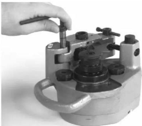
- Remove the hex screw retaining the drive roll with a 516 " hex key (Figure 8). If using the 8" - 12" or 4" - 6" rollset, remove the drive roll support bolts with a 38 " hex key.
natural_image
Close-up of a hand using a tool to adjust or install a mechanical component (no visible text or symbols)Figure 8 - Removing Hex Screw from Drive Roll
- Remove drive roll from drive shaft.
- Using a 1/8'' hex key, loosen set screw in reaction arm and remove groove roll shaft (Figure 9).
natural_image
Hand assembling a mechanical component with bolts and a small bolt (no visible text or symbols)Figure 9 – Loosening Set Screw in Reaction Arm
- Remove groove roll and thrust washers from reaction arm.
Installing New Rollset
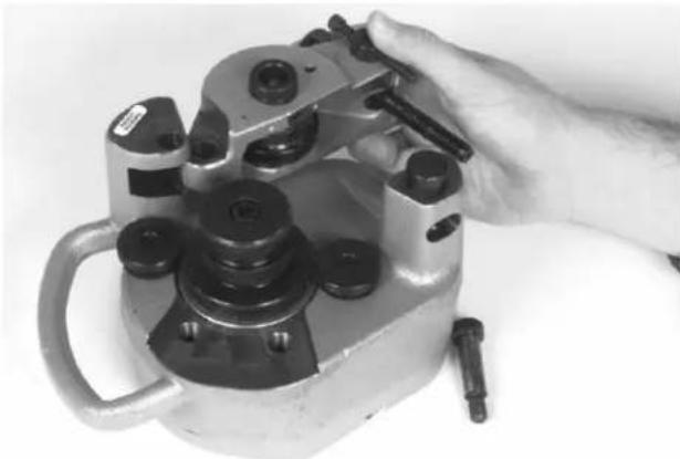
- Place the plain thrust washer at the back of the reaction arm slot. Place the tabbed thrust washer in the front of the reaction arm slot with the tab inserted in the small hole to the right of the groove roll shaft (Figure 10).
natural_image
Close-up of a hand adjusting a mechanical component with a circular spring and cylindrical housing (no visible text or symbols)Figure 10 – Placement of Thrust Washer
- Slide groove roll between the thrust washers in the reaction arm. Be sure that the groove roll is properly oriented with identification stamping in the "up" position.
- Look through the groove roll shaft hole and align the groove roll and thrust washers with the hole. Insert groove roll shaft (Figure 11).
natural_image
Hand adjusting a mechanical component with a handle and circular base (no visible text or symbols)Figure 11 – Inserting Groove Roll Shaft
- Tighten set screw in reaction arm with 18 " hex key to retain the groove roll shaft.
- Place drive roll over driveshaft. Be sure that the drive roll flange contacts the bronze thrust washer.
- Insert the hex screw into drive roll and tighten with 516 " hex key.
- If installing 4" - 6" Schedule 40 or 8" - 12" Schedule 10 drive rolls, install the screws into support housing and tighten with a 3/8 hex key (Figure 12).
natural_image
Close-up of a hand using a tool to adjust or install a mechanical component (no visible text or symbols)Figure 12 – Installing Drive Rolls
- If installing 8" - 12" Schedule 10 groove set, using a 3/_16 hex key, remove the 2" - 6" stabilizers and install 8" - 12" stabilizers (Figure 13).
natural_image
Close-up of a hand using a tool to adjust or install a mechanical component (no visible text or symbols)Figure 13 – Installing Stabilizers
Removing Roll Sets for the Installation of Copper Roll Set
- Place 915 on table with groove set up.
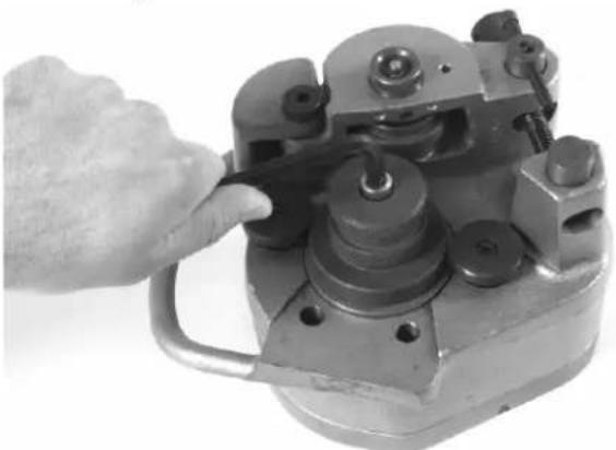
- Remove shoulder screw that retains the reaction arm to the main housing with 14 " hex key (Figure 14).
natural_image
Close-up of a hand using a tool to adjust or install a mechanical component (no visible text or symbols)Figure 14 – Removing Shoulder Screw
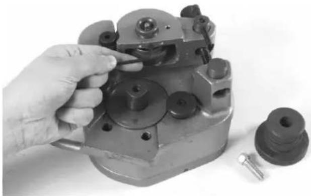
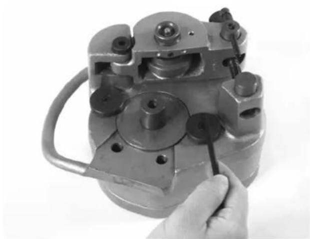
- Rotate feedscrew counter clockwise until free from pivot nut and remove reaction arm (Figure 15).
natural_image
Close-up of a hand holding a mechanical clamp or fixture with multiple bolts and a handle (no visible text or symbols)Figure 15 – Removing Feedscrew
- Using a 18 " hex key, remove set screw in reaction arm and remove groove roll shaft.
- Remove groove roll and thrust washers from reaction arm.
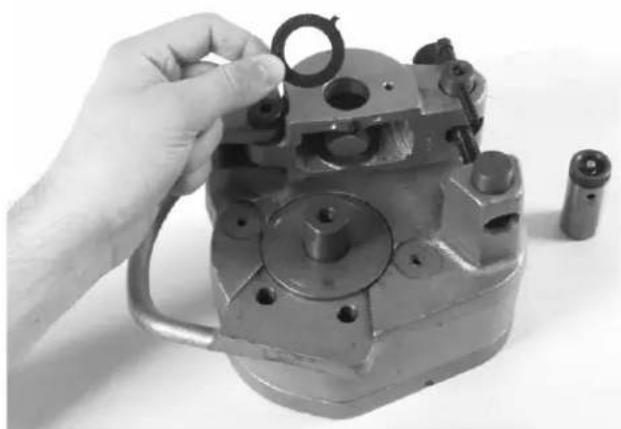
- Remove feedscrew from pivot pin. Remove pivot pin from reaction arm (Figure 16).
- Remove the hex screw retaining the drive roll with a 516 " hex key. If removing the 4" - 6" Sch. 40 or 8" - 12" Sch. 10 roll set, remove the drive roll support bolts using a 38 " hex key (Figure 16).
- Remove stabilizer pad on the handle side of the 915 using a 3/16'' hex key. If removing the 8'' - 12'' Sch. 10 roll set remove both stabilizer pads (Figure 16).
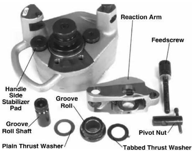
Figure 16 – Parts Call Out
Installing Copper Roll Set
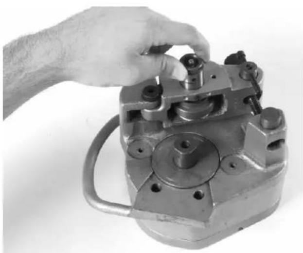
- Install copper stabilizer pad on handle side of 915 groover using the 3/16'' hex key (Opposite side stabilizer
should be standard 2" - 6" Sch. 10 stabilizer pad.) (Figure 17).
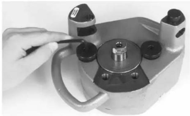
natural_image
Close-up of a hand using a tool to adjust or install a mechanical component (no visible text or symbols)Figure 17 – Installing Copper Stabilizer Pad
- Place the copper drive roll over driveshaft. Be sure that the drive roll flange contacts the bronze thrust washer.
- Insert the hex screw into the drive roll and tighten with 516 " hex key.
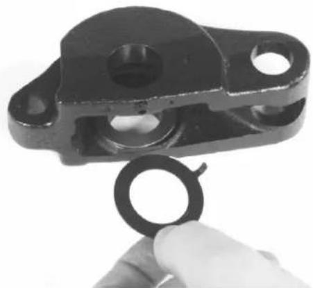
- Using the copper reaction arm (painted black), place the plain thrust washer at the back of the reaction arm slot. Place the tabbed thrust washer in the front of the reaction arm slot with the tab inserted in the small hole to the right of the groove roll shaft (Figure 18).
natural_image
Close-up of a hand holding a black mechanical component with a circular hole (no text or symbols visible)Figure 18 – Inserting Tabbed Thrust Washer
- Slide the groove roll between the thrust washers in the reaction arm. Be sure that the groove roll is properly oriented with the identification stamping in the "up" position.
-
Look through the groove roll shaft hole and align the groove roll and thrust washers with the hole. Insert groove roll shaft.
-
Install the set screw into the reaction arm and tighten with 18 " hex key to retain the groove shaft.
- Install the pivot pin into the copper reaction arm making sure the flat is in the "up" position so that it will accept the thrust washer and the head of the feedscrew (Figure 19).
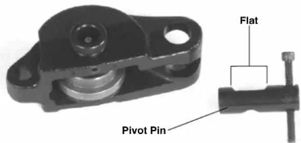
Figure 19 – Pivot Pin Position
- Insert the copper reaction arm into the slot in the main housing and install the shoulder screw. Tighten with 14 " hex key.
- Thread the feedscrew clockwise into the pivot nut.
Accessories
WARNING
Only the following RIDGID products have been designed to function with the 915 Roll Groover. Other accessories designed for use with other tools may become hazardous when used on this Roll Groover. To prevent serious injury, use only the accessories listed below.
Accessories for 915 Roll Groover
- Roll Set for 1^1/4'' - 1^1/2'' Sch. 10/40 Steel pipe
- Roll Set for 4" – 6" Sch. 40 Steel pipe
- Roll Set for 8" – 12" Sch. 10 Steel pipe
- Roll Set for 2" – 8" Copper Tube Types K, L, M, DWV
- Carrying Case for 915 Groover and Roll Sets
NOTE! A Roll Set consists of a Groove Roll and a Drive Roll. See Ridge Tool catalog for pipe stands and vises.
Maintenance Instructions
Lubrication with Lithium Base Grease
- Add grease to the fitting on the back cover until a small amount is seen at bronze thrust washer at front of unit.
- Add grease to fitting in the groove roll shaft until a small amount is seen at the side of groove roll.
- Lubricate the feedscrew and thrust washer.
Groove or Drive Rolls Maintenance
- Keep groove rolls clean. Use a wire brush to remove debris.
- Keep feedscrew clean.
- Inspect groove and drive rolls and replace if worn or damaged.
Tool Storage
⚠ WARNING Store the tool in a locked area that is out of reach of children and people unfamiliar with roll groover equipment. This tool can cause serious injury in the hands of untrained users.
Service and Repair
WARNING
Service and repair work on this Roll Groover must be performed by qualified repair personnel. Tool should be taken to a RIDGID Independent Authorized Service Center or returned to the factory. All repairs made by Ridge service facilities are warranted against defects in material and workmanship.
When servicing the Groover, only identical replacement parts should be used. Failure to follow these instructions may create a risk of serious injury.
If you have any questions regarding the service or repair of this machine, call or write to:
Ridge Tool Company
Technical Service Department
400 Clark Street
Elyria, Ohio 44035-6001
Tel: (800) 519-3456
E-Mail: rtctechservices@emerson.com
For name and address of your nearest Independent Authorized Service Center, contact the Ridge Tool Company at (800) 519-3456 or http://www.RIDGID.com
Table I. Standard Roll Groove Specifications ^1
NOTE! All Dimensions are in Inches.
| NOM. PIPE MIN. GASKET GROOVE GROOVE NOM. PIPE DIAMETER WALL SEAT WIDTH DIAMETER GROOVE | T | A | B | C | ||||
| SIZE | O.D. | TOL. | THK. | +.015/-.030 | +.030 | -0.015 | O.D. | TOL. ^2 DEPTH |
| 1^1/_4 | 1.660 | +.016-.016 | .065 | .625 | .281 | 1.535 | +.000-.015 | .063 |
| 1^1/_2 | 1.900 | +.016-.016 | .065 | .625 | .281 | 1.775 | +.000-.015 | .063 |
| 2 | 2.375 | +.024-.016 | .065 | .625 | .344 | 2.250 | +.000-.015 | .063 |
| 2^1/_2 | 2.875 | +.030-.018 | .083 | .625 | .344 | 2.720 | +.000-.015 | .078 |
| 3 | 3.50 | +.030-.018 | .083 | .625 | .344 | 3.344 | +.000-.015 | .078 |
| 3^1/_2 | 4.00 | +.030-.018 | .083 | .625 | .344 | 3.834 | +.000-.015 | .083 |
| 4 | 4.50 | +.035-.020 | .083 | .625 | .344 | 4.334 | +.000-.015 | .083 |
| 5 | 5.563 | +.056-.022 | .109 | .625 | .344 | 5.395 | +.000-.015 | .084 |
| 6 | 6.625 | +.050-.024 | .109 | .625 | .344 | 6.455 | +.000-.015 | .085 |
| 8 | 8.625 | +.050-.024 | .109 | .750 | .469 | 8.441 | +.000-.020 | .092 |
| 10 | 10.75 | +.060-.025 | .134 | .750 | .469 | 10.562 | +.000-.025 | .094 |
| 12 | 12.75 | +.060-.025 | .156 | .750 | .469 | 12.531 | +.000-.025 | .110 |
- As per AWWA C606-87.
- Nominal Groove Depth is provided as a reference dimension. Do not use groove depth to determine groove acceptability.
Table II. Pipe Maximum and Minimum Wall Thickness
NOTE! All Dimensions are in Inches.
| Pipe Size | CARBON STEEL OR ALUMINUM PIPE OR TUBE | STAINLESS STEEL PIPE OR TUBE | PVC PIPE | |||
| Wall Thickness | Wall Thickness | Wall Thickness | ||||
| Min. | Max. | Min. | Max. | Min. | Max. | |
| 1^1/_4'' | .065 | .140 | .065 | .140 | .140 | .140 |
| 1^1/_2'' | .065 | .145 | .065 | .145 | .145 | .200 |
| 2'' | .065 | .154 | .065 | .154 | .154 | .154 |
| 2^1/_2'' | .083 | .203 | .083 | .188 | .203 | .276 |
| 3'' | .083 | .216 | .083 | .188 | .216 | .300 |
| 3^1/_2'' | .083 | .226 | .083 | .188 | .226 | .226 |
| 4'' | .083 | .237 | .083 | .188 | .237 | 237 |
| 5'' | .109 | .258 | .109 | .188 | .258 | .258 |
| 6'' | .109 | .280 | .109 | .188 | .280 | .280 |
| 8'' | .109 | .148 | .109 | .188 | — | — |
| 10'' | .134 | .165 | .134 | .188 | — | — |
| 12'' | .156 | .180 | .156 | .188 | — | — |
Table III. Copper Roll Groove Specifications
| 1 | 2 | 3 | 4 | 5 | 6 | 7 | 8 | |
| Nom. Tubing Outside Gasket Groove Groove Size Inches | Diameter O.D. | A | B | Dia. | C | D | T | |
| Seat A ±0.03 | Min. Max. Width +.03 +.00 -.000 | Ref. -.02 | Depth 1 | Allow. Wall Thick. | Allow. Flare Dia. | |||
| Basic | Tolerance | |||||||
| 2" | 2.125 | ±0.002 | 0.610 | 0.300 | 2.029 | 0.048 | 0.064 | 2.220 |
| 2 ^1/_2 " | 2.625 | ±0.002 | 0.610 | 0.300 | 2.525 | 0.050 | 0.065 | 2.720 |
| 3" | 3.125 | ±0.002 | 0.610 | 0.300 | 3.025 | 0.050 | DWV | 3.220 |
| 4" | 4.125 | ±0.002 | 0.610 | 0.300 | 4.019 | 0.053 | DWV | 4.220 |
| 5" | 5.125 | ±0.002 | 0.610 | 0.300 | 5.019 | 0.053 | DWV | 5.220 |
| 6" | 6.125 | ±0.002 | 0.610 | 0.300 | 5.999 | 0.063 | DWV | 6.220 |
| 8" | 8.125 | +0.002/-0.004 | 0.610 | 0.300 | 7.959 | 0.083 | DWV | 8.220 |
- Nominal Groove Depth is provided as a reference dimension. Do not use groove depth to determine groove acceptability.
Troubleshooting
| PROBLEM CAUSE SOLUTION | ||
| Rolled Groove too narrow or too wide | Incorrect size of Grooving and Driving Rolls | Install correct size of Grooving and Driving Rolls |
| Mismatched Grooving and Driving Rolls | Match Grooving and Driving Rolls | |
| Grooving Roll and/or Driving Roll worn | Replace worn Roll | |
| Rolled Groove not perpendicular to pipe axis | Pipe length not straight | Use straight pipe |
| Pipe end not square with pipe axis | Cut pipe end square | |
| 915 will not track while grooving | Driving Roll knurl plugged or worn | Clean or replace drive roll |
| Feed Screw not tight | Tighten feed screw with ratchet for every revolution as per directions | |
| Turning Ratchet wrong direction | Turn Ratchet in proper direction | |
| Inside of pipe has too much scale | Clean inside of pipe | |
| 915 rocks from side to side on Driving Roll while grooving | Pipe end flattened or damaged | Cut off damaged pipe end |
| Hard spots in pipe material or weld seams harder than pipe | Hand feed Grooving Roll into pipe faster | |
| Grooving Roll feed rate too slow | Hand feed Grooving Roll into pipe faster | |
| 915 Groover will not roll groove pipe | Pipe wall maximum thickness exceeded | Check pipe capacity chart |
| Wrong rolls | Install correct rolls | |
| Pipe material too hard | Replace pipe | |
| Adjustment screw not set | Set depth | |
| 915 Groover will not roll groove to required diameter | Maximum pipe diameter tolerance exceeded | Use correct diameter pipe |
| Mismatched Grooving and Driving Rolls | Use correct set of Rolls | |
| Depth adjustment screw not set correctly | Adjust depth setting | |
| Pipe slips on Driving Roll | Grooving force too low | Tighten feed screw |
| Driving Roll knurling plugged with metal or worn flat | Clean or replace Driving Roll | |
natural_image
Ridgid 915 manual tool with handle and lever (no visible text or symbols beyond branding)Table des matières
CONSERVEZ CES INSTRUCTIONS!
CONSERVEZ CES INSTRUCTIONS!
natural_image
Ridgid 915 electric motor with attached wrench (no visible text or symbols on body)natural_image
Silhouette of a person pushing a block with an arrow indicating motion (no text or symbols)
natural_image
Silhouette of a person interacting with two gears (no text or symbols)natural_image
Simple black-and-white icon of a person with an arrow pointing left (no text or symbols)
natural_image
Silhouette of a person interacting with two gears (no text or symbols)natural_image
Close-up of a mechanical coupling or bracket component (no visible text or symbols)natural_image
Close-up of a hand pouring liquid into a mechanical component (no visible text or symbols)natural_image
Close-up of a hand holding a metal tool with a wrench, next to a mechanical component (no visible text or symbols)Figure 6 – Rainurage du tuyau
natural_image
Close-up of a hand adjusting a BIGID industrial pump component (no visible text or symbols)natural_image
Close-up of a hand using a mechanical clamp or tool to adjust a mechanical component (no visible text or symbols)natural_image
Hand operating a mechanical tool with multiple holes and a small bracket (no visible text or symbols)natural_image
Close-up of a hand adjusting a mechanical component with a circular spring and multiple holes (no visible text or symbols)natural_image
Hand adjusting a mechanical component with a handle and mounting holes (no visible text or symbols)natural_image
Close-up of a hand using a tool to adjust or install a mechanical component (no visible text or symbols)natural_image
Close-up of a hand using a tool to adjust or install a mechanical component (no visible text or symbols)natural_image
Close-up of a hand using a mechanical tool to adjust or install a mechanical component (no visible text or symbols)Figure 14 – Retrait de la vis de fixation
natural_image
Hand holding a mechanical clamp or crimp in a metal frame, no visible text or symbolsnatural_image
Close-up of a hand using a tool to adjust or install a mechanical component (no visible text or symbols)natural_image
Hand holding a black mechanical component with a circular ring (no text or symbols visible)Technical Service Department
400 Clark Street
Elyria, Ohio 44035-6001
Tél. : (800) 519-3456
E-mail : rtctechservices@emerson.com
natural_image
Ridgid 915 manual tool with handle and mounting bracket (no text or symbols on device body)Indice
natural_image
Ridgid 915 electric motor with attached wrench (no visible text or symbols on body)Figura 1 – Ranuradora a Rodillos No. 915
Accesorios
natural_image
Abstract black geometric shape on white background (no text or symbols)
natural_image
Silhouette of a person interacting with two gears (no text or symbols)natural_image
Simple black-and-white icon of a person with a directional arrow, no text or symbols present
natural_image
Silhouette of a person interacting with two gears (no text or symbols)natural_image
Close-up of a mechanical component with bolts and a cylindrical shaft (no visible text or symbols)natural_image
Close-up of a hand pouring liquid into a mechanical pipe fitting (no visible text or symbols)natural_image
Close-up of a hand wearing a RIDGID Ridge Tool Company wristband, holding a mechanical clamp (no visible text or symbols on the tool itself)Figura 6 – Ranurado de un tubo
natural_image
Close-up of a hand adjusting a metal mechanical component with a bolt, labeled 'RIGID 915' (no other text or symbols visible)natural_image
Close-up of a hand using a tool to adjust or install a mechanical component (no visible text or symbols)natural_image
Hand assembling a mechanical component with a bolt and nut (no visible text or symbols)natural_image
Hand holding a mechanical component with a circular hole, next to a small cylindrical component (no visible text or symbols)natural_image
Hand adjusting a mechanical component with a handle and circular base (no visible text or symbols)natural_image
Hand using a tool to adjust or install a mechanical component (no visible text or symbols)natural_image
Hand using a tool to adjust or install a mechanical component (no visible text or symbols)natural_image
Close-up of a hand using a mechanical tool to adjust or install a cylindrical component (no visible text or symbols)natural_image
Hand holding a mechanical clamp or tool, with no visible text or symbolsnatural_image
Close-up of a hand using a tool to adjust or install a mechanical component (no visible text or symbols)natural_image
Close-up of a hand holding a black mechanical component with circular holes (no text or symbols visible)Elyria, Ohio 44035-6001
RIDGID ^3 tools are warranted to be free of defects in workmanship and material.
How long coverage lasts
This warranty lasts for the lifetime of the RIDGID® tool. Warranty coverage ends when the product becomes unusable for reasons other than defects in workmanship or material.
How you can get service
To obtain the benefit of this warranty, deliver via prepaid transportation the complete product to RIDGE TOOL COMPANY, Elyria, Ohio, or any authorized RIDGIDs INDEPENDENT SERVICE CENTER. Pipe wrenches and other hand tools should be returned to the place of purchase.
What we will do to correct problems
Warranted products will be repaired or replaced, at RIDGE TOOL'S option, and returned at no charge; or, if after three attempts to repair or replace during the warranty period the product is still defective, you can elect to receive a full refund of your purchase price.
What is not covered
Failures due to misuse, abuse or normal wear and tear are not covered by this warranty. RIDGE TOOL shall not be responsible for any incidental or consequential damages.
How local law relates to the warranty
Some states do not allow the exclusion or limitation of incidental or consequential damages, so the above limitation or exclusion may not apply to you. This warranty gives you specific rights, and you may also have other rights, which vary, from state to state, province to province, or country to country.
No other express warranty applies
This FULL LIFETIME WARRANTY is the sole and exclusive warranty for RIDGID® products. No employee, agent, dealer, or other person is authorized to alter this warranty or make any other warranty on behalf of the RIDGE TOOL COMPANY.

Ce qui est couvert
Elyria, Ohio 44035-6001
U.S.A.

Qué cubre
Commercial & Residential Solutions