ProPress XL-C - Drill RIDGID - Free user manual and instructions
Find the device manual for free ProPress XL-C RIDGID in PDF.
| Product Type | Hydraulic pressing tool for ProPress fittings |
| Brand | RIDGID |
| Model | ProPress XL-C |
| Intended Use | Permanent pressing of ProPress and ProPress XL-C fittings on pipes |
| Compatible Materials | Copper, stainless steel (depending on ProPress fittings) |
| XL-C Ring Diameters | 2½ in, 3 in, 4 in |
| XL-C Ring Weights | 2.48 kg (2½ in), 4.37 kg (3 in), 5.03 kg (4 in) |
| Required Actuator | Type V2 (RIDGID) |
| Compatible Pressing Tools | Standard Series: CT-400, 320-E, RP 330, RP 340 |
| Power Source | Rechargeable battery (depending on pressing tool) |
| Cycle Time | 4 to 8 seconds |
| Safety | Automatic cycle lock, calibration device (320-E), crush protection |
| Maintenance | Clean surfaces with Scotch-Brite pad, monthly lubrication of pins |
| Spare Parts | None available – accessories must be replaced entirely |
| Warranty | Full Lifetime Warranty |
| Included Accessories | Carrying case (ref. 21103), rings and actuator sold separately |
| Storage | Indoors, protected from weather, out of reach of children |
Frequently Asked Questions - ProPress XL-C RIDGID
User questions about ProPress XL-C RIDGID
0 question about this device. Answer the ones you know or ask your own.
Ask a new question about this device
Download the instructions for your Drill in PDF format for free! Find your manual ProPress XL-C - RIDGID and take your electronic device back in hand. On this page are published all the documents necessary for the use of your device. ProPress XL-C by RIDGID.
USER MANUAL ProPress XL-C RIDGID
Pressing Tools for Use With:
ProPress® Fitting System
ProPress® XL-C Fitting System
WARNING!
Read this Operator's Manual carefully before using this tool. Failure to understand and follow the contents of this manual may result in extensive property damage and/or serious personal injury.
Table of Contents
Safety Symbols....1
Specific Safety Information
Pressing Tool Safety ....1
Description and Specifications
Description....2
Specifications....2
Inspecting the Press Tool and Attachments ....3
Tool and Work Area Set-Up
Mounting Attachment Into Press Tool 4
Preparing The Connection
Preparing the Tube 5
Inserting the Tube Into the Fitting 5
Operating Instructions
Pressing the Connection with a Jaw Set 6
Pressing the Connection with a Ring and Actuator ....7
Inspecting the Press Connection ....8
Maintenance Instructions 9
Accessories
ProPress System For Copper Tubing 9
Maintenance Storage 9
Service and Repair....10
Clearance Requirements 10-13
Troubleshooting....14
Lifetime Warranty ....Back Cover
*Original Instructions - English
Safety Symbols
In this operator's manual and on the product, safety symbols and signal words are used to communicate important safety information. This section is provided to improve understanding of these signal words and symbols.

This is the safety alert symbol. It is used to alert you to potential personal injury hazards. Obey all safety messages that follow this symbol to avoid possible injury or death.

DANGER indicates a hazardous situation which, if not avoided, will result in death or serious injury.

WARNING WARNING indicates a hazardous situation which, if not avoided, could result in death or serious injury.

CAUTION CAUTION indicates a hazardous situation which, if not avoided, could result in minor or moderate injury.
NOTICE
NOTICE indicates information that relates to the protection of property.

This symbol means read the operator's manual carefully before using the equipment. The operator's manual contains important information on the safe and proper operation of the equipment.

This symbol means always wear safety glasses with side shields or goggles when handling or using this equipment.

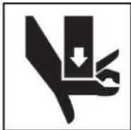
This symbol indicates the risk of hands, fingers or other body parts being crushed

This symbol indicates the risk the electrical shock.
Specific Safety Information
WARNING
This section contains important safety information that is specific to this tool.
Read these precautions carefully before using the Press Tool Attachments to reduce the risk of serious personal injury.
SAVE THESE INSTRUCTIONS!
A compartment in the Press Tool carrying case is included to keep this manual with the machine for use by the operator.
Pressing Tool Safety
- Only use RIDGID® Pressing Tool with RIDGID Pro - Press jaws and Press rings. Other uses or modifying the jaws for other applications may damage the pressing tool, damage the jaws and/or cause personal injury.
- Keep your fingers and hands away from jaws, press rings and ring actuator during pressing cycle. Your fingers or hands can be crushed, fractured or amputated if they become caught between the jaws, press rings or ring actuator or between these components and any other object.
- Never attempt to repair a damaged jaw set actuator, or press ring. A jaw, actuator or press ring that has been welded, ground, drilled or modified in any manner can shatter during pressing resulting in serious
injury. Discard the entire damaged jaw set. Re place with a new jaw set. Never replace individual components except for damaged jaw return springs. Please call Ridge Tool Company, Technical Service Department for availability.
- Read and understand this manual, the tool operator's manual, the fitting manufacturer's installation instructions and the instructions for any other equipment used with this tool before operating.
Failure to follow all instructions may result in property damage and/or serious injury.
NOTICE Selection of appropriate materials and joining methods is the responsibility of the system designer and/or installer. Before any installation is attempted, careful evaluation of the specific service environment, including chemical environment and service temperature, should be completed.
If you have any question concerning this RIDGProduct:
- Contact your local RIDGID distributor.
- Visit www.RIDGID.com or www.RIDGID.eu to find your local RIDGID contact point.
- Contact Ridge Tool Technical Service Department at rttechservices@emerson.com, or in the U.S. and Canada call (800) 519-3456.
Description and Specifications
Description
RIDGID Press Tool Attachments for ProPressSystems, when used with the appropriate RIDGID Press Tool, are designed to mechanically press ProPress fittings onto tubing to create a watertight and permanent seal. When the switch on the press tool is depressed, a motor powers a hydraulic pump which forces fluid into the press tool cylinder. This moves the tool rollers forward into contact with the attachment and applies thousands of pounds of force to the specially designed fitting.
NOTE! ProPress® is a registered trademark of Viega GmbH & Co.
The entire pressing cycles takes between 4 and 8 seconds starting from when the switch is pressed. Once the pressing tool starts to deform the fitting, the tool will automatically continue the press until complete.
There are RIDGID Press Tool attachments for the following ProPress Systems:
- ProPress
• ProPress XL-C
ProPress
RIDGID makes jaw sets, rings and actuators to press ProPress fittings. These include:
- Standard Series ProPress Jaw sets for ^1/2 " to 2" ProPress fittings
- Compact Series ProPress Jaw sets for ^1/2 " to 1^1/4 " ProPress fittings
- ProPress Rings for 12 to 2" ProPress fittings:
- 1^1/2 and 2 ProPress Rings are used with Standard Series Press Tools with the V2 actuator
- ^1/2 " to 1 ^1/4 " ProPress Rings can be used with the Standard Series Press Tools with the V1 Actuator, or with the Compact Series Press Tools with the C1 actuator
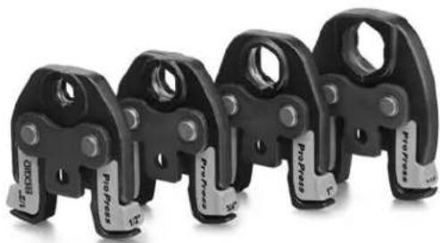
Standard Series ProPress Jaw Sets
Standard Series ProPress Jaw Sets are designed to mechanically press ProPress fittings onto", 3/4", 1", 1/4", 1½" and 2" tubing. An individual jaw set is required for each size tubing. Standard Series Jaw sets are designed to be used with RIDGID Standard Series Press Tools such as the CT-400, 320-E, RP 330 and RP 340. Standard Series Jaw Sets cannot be used with RIDGID Compact Series press tools such as the 100-B, RP 200 and RP 210. Jaw sets and press tools must be used perpendicular to the fitting/tube being pressed.
| Catalog No. ize Weight | ||
| 76652 | 1/2" 3.75 lbs. (1,70 kg) | |
| 76657 | 3/4" 3.90 lbs. (1,76 kg) | |
| 76662 1 | " 4.15 lbs. (1,88 kg) | |
| 76667 1 | 1/4" | 4.30 lbs. (1,95 kg) |
| 76672 1 | 1/2$ " | 6.45 lbs. (2,93 kg) |
| 76677 2 | " 9.40 lbs. (4,26 kg) | |

natural_image
Row of black industrial clamping tools with metallic fittings, no visible text or symbolsFigure 1 – Standard Series ProPress Jaw Set
Compact Series ProPress Jaw Sets
Compact ProPress Jaw Sets are designed to mechanically press ProPress fittings onto 12 , 34 , 1" and 114 " tubing. An individual jaw set is required for each size tubing. Compact Series Jaw sets are designed to be used with RIDGID Compact Series Press Tools such as the 100-B, RP 200 and RP 210. Com pact Series Jaw Sets cannot be used with RIDGID Standard Series press tools such as the CT-400, 320-E, RP 330 and RP 340. Jaw sets and press tools must be used perpendicular to the fitting/tube being pressed.
| Catalog No. | Size | Weight |
| 16958 | 1/2" | 2.5 lbs. (1,14 kg) |
| 16963 | 3/4" | 2.22 lbs. (1,01 kg) |
| 16978 | 1" 2.28 lbs. | (1,03 kg) |
| 31228 | 114" | 2.56 lbs. (1,15 kg) |
natural_image
Four black industrial clamping cranes with visible fasteners and mounting holes (no text or symbols)Figure 2 – Compact Series ProPress Jaw Set
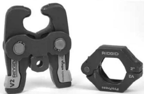
ProPress Rings
ProPress Rings are designed to mechanically press ProPress fittings onto 12 , 34 " 1", 14 ", 112 " and 2" tubing. An individual ring is required for each tubing size through
1 ^1/4 " rings can be actuated with either a V1 actuator and Standard Series Press Tools such as the CT-400, 320-E, RP 330 or RP 340, or a C1 actuator and Compact Series Press Tools such as the 100-B, RP 200 and RP 210 ^1/2 l and 2" rings can only be actuated with the V2 actuator and Standard Series Press Tools. ^1/2 " and 2" ProPress rings cannot be actuated with Compact Series Press Tools.
The ProPress rings must be used perpendicular to the fitting and tube being pressed but the ball pocket/tip feature on the rings and actuators allows the actuator and press tool to swivel up to 90 degrees in each direction. This allows the rings and actuators to be used in some applications where the jaw sets and pressing tool will not fit. The ProPress rings are marked to show the correct actuator for use with that ring.
| Catalog No. | Description Weight | |
| 27998 | 12 " ProPress Ring 0.50 lbs (0,23 kg) | |
| 28003 | 34 " ProPress Ring 0.70 lbs (0,32 kg) | |
| 28008 1" | ProPress Ring 0.90 lbs (0,41 kg) | |
| 28013 1 | 14 " ProPress Ring 1.00 lbs (0,45 kg) | |
| 28018 1 | 12 " ProPress Ring 1.35 lbs (0,61 kg) | |
| 28023 2" | ProPress Ring 2.00 lbs (0,91 kg) | |
| 26163 | C1 Actuator 2.10 lbs (0,95 kg) | |
| 28033 | V1 Actuator | 4.80 lbs (2,18 kg) |
| 21878 | V2 Actuator | 4.7 lbs (2,13 kg) |
natural_image
Two black industrial crimping tools: one with V2 and label 'RIDGID', the other with 2" and 2" labels (no text or symbols on the tools themselves)Figure 3 – ProPress Ring and V2 Actuator
ProPress XL-C
RIDGID makes ProPress XL-C Rings for use with ProPress XL-C Fittings. ProPress XL-C Rings are de signed to mechanically press ProPress XL-C fittings only 23" and 4" tubing. An individual ring is required for each tubing size. ProPress XL-C Rings are actuated with V2 actuators and Standard Series Press Tools such as the CT-400, 320-E, RP 330 or RP 340. ProPress XL-C Rings cannot be used with the Compact Series Press Tools.
The ProPress XL-C rings must be used perpendicular to the fitting and tube being pressed but the ball pocket/tip
feature on the rings and actuators allows the actuator and press tool to swivel up to 90 degrees in each direction.
| Catalog No. | Size | Weight |
| 20543 | 2 12 " XL-C Press Ring | 5.46 lbs (2,48 kg) |
| 20548 | 3" XL-C Press Ring | 9.63 lbs (4,37 kg) |
| 20553 | 4" XL-C Press Ring | 11.08 lbs (5,03 kg) |
| 21878 | V2 Actuator | 6.71 lbs (3,04 kg) |
| 21103 | Carrying Case | 6.15 lbs (2,79 kg) |
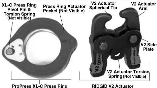
text_image
XL-C Press Ring Pivot Pin & Torsion Spring (Not visible) Press Ring Actuator Pocket (Not Visible) ProPress XL-C Press Ring V2 Actuator Spherical Tip V2 Actuator Arm V2 Side Plate V2 Actuator Torsion Spring (Not visible) RIDGID V2 ActuatorFigure 4 – ProPress XL-C Press Ring and RIDGID V2 Actuator
⚠ WARNING Only use RIDGID Press Tools and RIDGID press tool attachments (jaw sets, rings, actuators, etc.) when specified by the fitting manufacturer for use with their system. Use of incorrect press tools and/or attachments for a system can cause system leaks, damage the press tool or attachment, void warranties or cause severe personal injury.
NOTICE Contact the fitting manufacturer for specific information on their system, including compatible tubing, materials, installation instructions, minimum distance between fittings, seal material, inspection, testing, etc. Incorrect installation can cause system leaks and extensive property damage.
Contact Ridge Tool Technical Service Department at (800) 519-3456 or rttechservices@emerson.com for a list of press fitting system and valve manufacturers that specify RIDGID pressing tools and attachments for their systems.
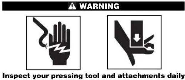
Inspecting the Press Tool and Attachments
text_image
WARNING Inspect your pressing tool and attachments dailyand correct any problems to reduce the risk of serious injury from electric shock, tool and attachment failure and other causes and to prevent tool and property damage.
- Inspect press tool according to the specific tool operator's manual.
- Clean any oil, grease or dirt from the tool and attachments, especially the handles and controls. This reduces the risk of the tool or attachment slipping from your grip and makes inspection easier.
- Closely inspect all pressing attachment components (jaw sets, rings, actuators, etc.) for any cracked, broken, worn, missing, misaligned or binding parts or any other sign of damage that may prevent proper and safe operation. Damaged parts can cause the attachment to make incorrect pressed connections or fail during use, and cause serious injury or property damage. If any damage is found, the attachment should discarded and replaced. (See Figure 14.)
⚠ WARNING Always discard the complete pressing attachment. Never replace individual components or exchange parts between assemblies. Failure to replace the entire assembly may result in component failure and serious injury.
Do not modify pressing attachments or use modified attachments. A pressing attachment component that has been welded, ground, drilled or modified in any manner can shatter during pressing, resulting in sharp flying objects, severe injury or death. Discard and replace damaged pressing attachments.
- Inspect the attachment markings to make sure that it is clearly marked as to the system and size that it is appropriate for. Do not use an attachment that is not clearly marked.
- Inspect the press profile of the attachment. If it is rusty, dirty or if there is a build up of fitting material, clean as described in the maintenance section. It is important to keep the press profile clean to prevent the formation of burrs during pressing process, prevent the attachment from sticking to the fitting and making sure that a proper press connection is made.
- Make sure that springs are intact and bias the attachment in the proper direction (closed for rings, jaws and actuators). Attachment should cycle freely from the fully open to fully closed position. If needed, lubricate pivot points with a light lubricating oil. Wipe any excess oil from the attachment.
Tool and Work Area Set-Up
WARNING


Set up the press tool, attachment and work area according to these procedures to reduce the risk of injury from electric shock and other causes and to prevent property damage.
- Inspect the work to be done and determine
• The system of fittings to be used
• The sizes of fittings to be used - The amount of space available for the tool and attachments to make the pressed connections.
- Determine the appropriate pressing tool and attachments for the application. See the Description and Specification section for information on the attachments available for the ProPress systems. Information on clearance requirements for various attachments can be found at the back of the manual. Information on RIDGID Pressing Tools and other RIDGID press tool attachments can be found at www.RIDGID.com, or by contacting Ridge Tool Technical Services at (800) 519-3456 or rttechservices@emerson.com.
Only use RIDGID Press Tools and RIDGID press tool attachments (jaw sets, rings, actuators, etc.) when specified by the fitting manufacturer for use with their system. Be sure to use the correct actuator for the ring being used. Rings are marked to indicate the correct actuator for use with the ring. Use of in -correct press tools and/or attachments for a system can cause system leaks, damage the press tool and attachment or cause severe personal injury. - Make sure that the press tool and attachment have been inspected according to their respective manuals or instructions.
- Follow tool set up procedure according to the specific press tool operator's manual.
Mounting Attachment Into Press Tool
- Make sure that the press tool is unplugged or that the battery is removed from the tool.
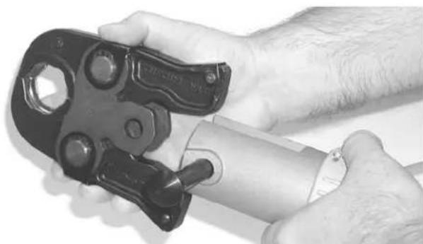
- Pull the attachment mounting pin on the press tool out. If there is already an attachment in the tool, slide it out of the pressing tool (See Figure 5).
natural_image
Close-up of hands using a crimping tool to handle a cylindrical pipe (no visible text or symbols)Figure 5 – Pulling The Jaw Set Mounting Pin Out
- Slide the attachment into the press tool and fully engage the attachment mounting pin. The press tool will not function unless the pin is fully engaged.
Calibrating The Pressing Tool For The Specific Pressing Attachment (320-E Pressing Tool Only)
The RIDGID 320-E Pressing Tool includes a feature to help insure that complete press connections are made. To use this feature, when a press attachment is installed on the 320-E, a calibration cycle is done. The 320-E then compares that calibration cycle to each press connection made. If the press connection does not match the calibration cycle, the 320-E alerts the user that a pressing error has occurred so that the operator can take appropriate action.
See the 320-E manual or contact Ridge Tool Technical Service if you have any questions regarding this feature.
Preparing The Connection
NOTICE These are generalized instructions. Always follow the fitting manufacturers specific installation instructions. Failure to follow the fitting manufacturer's installation instructions may lead to an improper press connection and cause leaking connections and property damage.
Preparing the Tube
-
If necessary, cut the desired length of the proper tube for use with the fitting system. Use a tubing cutter or other method that provides a clean cut square to the axis of the tube. If using a vise or other method to hold the tube during cutting, make sure that the vise is far enough from the end of the tube not to damage the section of tube that is inserted into the fitting. Scratches on the outside diameter of the tube and deformed tube can cause leaks.
-
Deburr the tube end inside and out with a file, reamer, deburring tool or other suitable tool. Burrs can cut the sealing element of the fitting and cause leaks.
-
Clean the end of the tube of all dirt, oil and grease. Improperly prepared tube can cause improper connections, leaks and other property damage.
Inserting the Tube into the Fitting
- Inspect the fitting per the manufacturer's instructions to be sure all parts are present, in place and free of dirt and debris. If fitting parts are missing or dirty, this can cause improper connections, leaks and other property damage. See Figure 7.

natural_image
Side profile of a man in suit and glasses holding a small ring, no visible text or symbolsFigure 6A – Inspection of the ProPress Fitting per the Manufacturer's Instructions
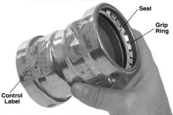
text_image
Control Label Seal Grip RingFigure 6B – Inspection of XL-C Fitting Prior to Tube Insertion
- In some systems, there is a requirement to mark the tube before insertion. Check the fitting manufacturer's instructions, and if required, mark the tubing with a permanent marker at the appropriate distance from the tube end. This gives a visual reference that the tube has been fully inserted into the fitting prior to pressing the connection. See Figure 7.
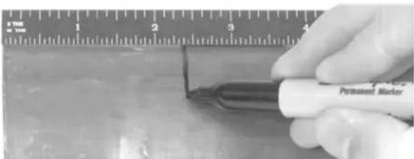
text_image
Permanent MarkerFigure 7 – Marking the Tube Before Inserting Into Fitting
-
Fully insert the tube into the fitting. Most fittings have a stop that the tube end contacts to indicate full insertion. Other fittings do not have a stop and will allow the tube to fully pass through the fitting, and are typically used in repair applications. If there is no stop, insert the tube so that the mark made in the previous step is even with the end of the fitting. In some cases, a twisting motion during insertion makes the process easier. Never use any lubricant unless the fitting manufacturer specifically advises to. Lubricants can degrade the seal and cause leaks. Tubing that is difficult to insert may be out of round or have burrs on the tube end, which can damage the seal and cause leaks.
-
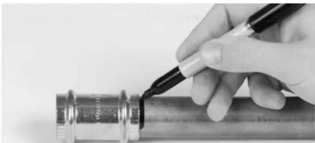
Make sure that the tube is fully inserted in the fitting and if not marked in previous steps, mark the tube at the end of the fitting to give a visual reference that the tube is fully inserted. See Figures 8 and 9.
natural_image
Close-up of a hand holding a pen writing on a metallic pipe fitting (no visible text or symbols)Figure 8 – Marking the Tubing After Fully Inserting Tube
text_image
Close-up of a hand holding a metallic mechanical component with warning labels and safety symbolsFigure 9 – Inserting the Tube Into Fitting to Proper Depth
Operating Instructions
WARNING

Always wear eye protection to protect your eyes against dirt and other foreign objects.
Keep your fingers and hands away from the tool attachment during the pressing cycle. Your fingers or hands can be crushed fractured or amputated in the attachment or tool or between the attachment, work piece and other objects.
Follow operating instructions to reduce the risk of injury from crushing and other causes and to prevent tool damage.
⚠ WARNING Only use RIDGID Press Tools and RIDGID press tool attachments (jaw sets, rings, actuators, etc.) when specified by the fitting manufacturer for use with their system. Use of incorrect press tools and/or attachments for a system can cause system leaks, damage the press tool or attachment, void warranties or cause severe personal injury.
Confirm that the tool and attachments have been properly set up.
Pressing the Connection with a Jaw Set
- Squeeze the jaw arms to open the Jaw set and place the open jaws around the fitting. Allow the jaw set to close around the fitting, making sure to align the press profile of the jaw set with the contour of the fitting (See Figure 10).
natural_image
Close-up of a mechanical clamp or bracket with metal fittings and bolts (no visible text or symbols)Figure 10 – Opening the Jaw set and Placing Around Fitting
-
Confirm that the tubing is inserted to the proper depth in the fitting. As specified in appropriate Fitting System instructions.
-
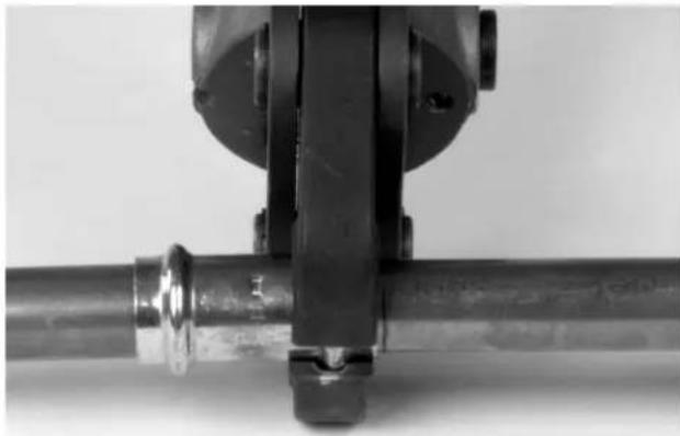
Make sure that the jaw set and pressing tool are square to the tube and fitting (See Figure 11) and depress the press tool switch. Keep fingers and hands away from the jaw set to avoid crushing injuries in jaw set and between the jaw set and the surroundings.
natural_image
Close-up of a mechanical assembly with a metallic pipe and clamping mechanism (no visible text or symbols)Figure 11 – Jaw Set Square To Fitting and Tubing
The pressing cycle takes 4-8 seconds depending on the press tool. Once a press cycle begins and the rollers contact the Jaw set, the press tool will lock on and automatically complete the press cycle. Releasing the tool switch will not stop the tool once the pressing process has begun. This insures consistent, repeatable press connection integrity. If the tool should malfunction, refer to the specific press tool operator's manual.
- Press the jaw set jaw arms to open the jaw set and remove from the fitting. Avoid any sharp edges that may have formed on fitting during pressing operation.
Pressing the Connection with a Ring and Actuator
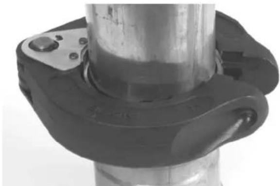
- Open the appropriate Press Ring and place squarely around the fitting. Allow the ring to close around the fitting, making sure to align the press profile with the contour of the fitting. If the ring is not properly aligned with the fitting, an improper press connection will be made. See Figures 12A and B.
natural_image
Close-up of a mechanical component with a cylindrical shaft and flange (no visible text or symbols)Figure 12A – Installing ProPress XL-C Press Ring Onto Fitting
natural_image
Close-up of a metallic pipe fitting with flange and central shaft (no visible text or symbols)Figure 12B – Installing ProPress Ring Onto Fitting
- Confirm that the appropriate actuator for the ring to be pressed is in the pressing tool (the ring will be marked with the designation of the appropriate actuator - C1, V1, V2). The correct actuator/ring combination must be used to prevent possible injury, ring and actuator damage, and improper press connections.
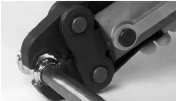
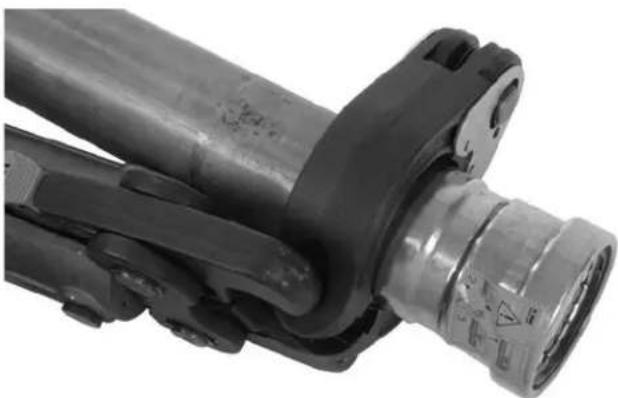
- Squeeze the actuator arms to open the actuator tips, place tips in ring pockets and allow the actuator to close down and seat into the pockets. See Figure 14A - B. The C1, V1 and V2 actuators and their mating rings are designed to allow the actuator and tool to be rotated up to ninety degrees each way from perpendicular. Actuator tips must be fully engaged in ring pockets.
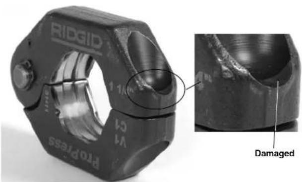
NOTICE Misaligning actuator tip to ring pocket can damage the ring or actuator during pressing. Make sure that the actuator tips are fully engaged in the ring pockets. (See Figure 13.)
text_image
RIDGID PROPress 1/1 V4 CA DamagedFigure 13 – Damaged Ring Pocket
natural_image
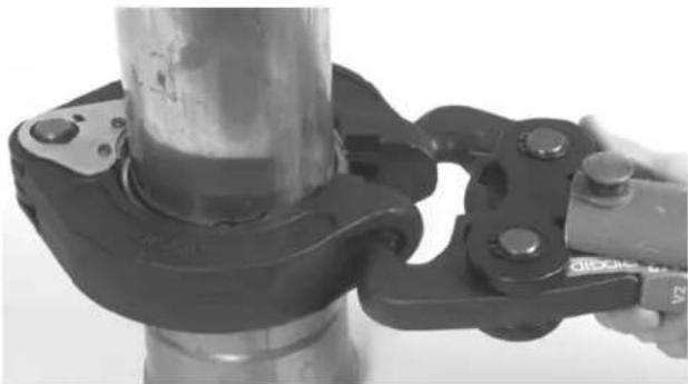
Close-up of a hand using a pliers to adjust a cylindrical mechanical component (no visible text or symbols)Figure 14A – Placing V2 Actuator Tips Into XL-C Ring Pockets
natural_image
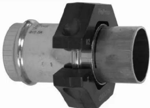
Close-up of a mechanical assembly with black and metallic components (no visible text or symbols)Figure 14B – Placing V2 Actuator Into XL-C Ring Pockets At An Angle For Additional Clearance
Do not hang the actuator and tool from the ring. The tool and actuator could fall from the ring and cause serious injury or death.
- Make sure that the ring is square to the tube and fitting and depress the press tool switch. Keep fingers and hands away from the actuator and ring to avoid crushing injuries in the attachments and between the attachments and surroundings.
The pressing cycle takes 4-8 seconds depending on the press tool. Once a press cycle begins and the
rollers contact the actuator, the press tool will lock on and automatically complete the press cycle. Re-leasing the tool switch will not stop the tool once the pressing process has begun. This insures consistent, repeatable press connection integrity. If the tool should malfunction, refer to the specific press tool operator's manual.
The ProPress rings and the ProPress XL-C rings are designed to fully close during the pressing process.
-
After the pressing operation is complete, squeeze the actuator arms to open the actuator tips and remove from the ring.
-
Remove the ring from the fitting. Avoid any sharp edges that may have formed on the fitting during the pressing operation.
Inspecting The Press Connection
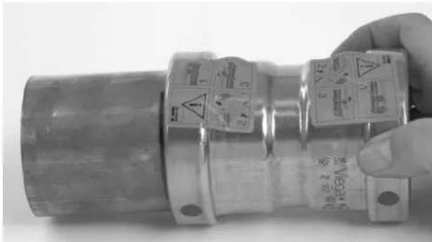
- Inspect the pressed fitting. If the fitting is supplied with a control label by the fitting manufacturer, remove it (Refer to Figures 6B). Control labels are supplied by the manufacturer to indicate that the fitting has not yet been pressed. Removal of the control label indicates to others that the connection has been pressed.
Look for the following:
- Excessive misalignment of the tubes. Note that a slight amount of misalignment at the pressed connection is considered normal.
- Tubes that are not fully inserted into the fitting – double check the insertion marks made on the tube to see that they are still aligned with the end of the fitting.
- Incorrect jaw or ring alignment with the fitting contour, distorted or deformed fitting.
- Any other issues per the fitting manufacturer. If any of these problems are found, then removal of the fitting is required and a new fitting and tube will need to be prepared and pressed in its place.
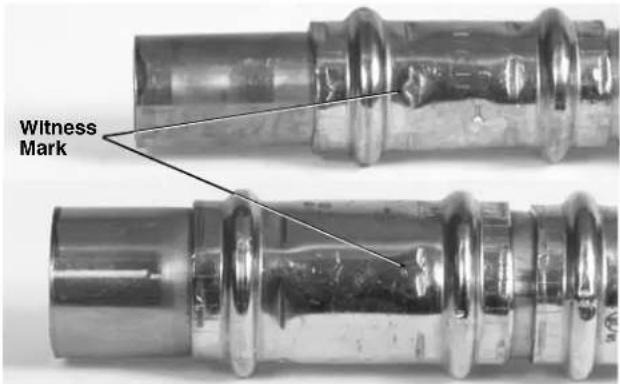
- If inspecting ProPress fittings, check and confirm the presence of the ProPress witness mark in one of the hex flats (See Figure 15). This unique mark confirms that the proper RIDGID Jaw set, designed specifically for the ProPress Fitting System was used to make the pressed connection. This witness mark is a trade mark of the Ridge Tool Company. Absence of the witness mark may invalidate the system manufacturer's warranty. The ProPress XL-C systems do not have a witness mark.
text_image
Witness MarkFigure 15 – ProPress Witness Mark
- Test the system in accordance with the system suppliers instructions, normal practice and local codes. The system supplier may have specific system test procedures to confirm the integrity of the system.
Maintenance Instructions
WARNING
Press attachments should be removed from press tool before performing any maintenance.
Always wear safety glasses. Protect your eyes from dirt and other foreign objects.
A jaw, press ring or ring actuator component that has been welded, ground, drilled or modified in any manner can shatter during pressing, resulting in sharp flying objects, severe injury or death. Discard and replace damaged jaws, press rings or ring actuators.
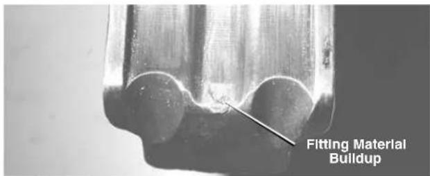
- Before use, inspect the press profile. If damaged, discard the attachment. If rusty, dirty or if there is evidence of fitting material build up or other contaminants, manually clean the press profile. Contaminants in the press area (especially near the tips of scissor style jaws or press rings - see Figure 16) make it more likely that burrs will form on the fitting during pressing. Burrs can damage the attachment press profile.
text_image
Fitting Material BuildupFigure 16 – Fitting Material Build-Up In Press Profile
Use a fine grade Scotch-Brite/Scotch-Brite is a registered trademark of the 3M Company) metal polishing pad, steel wool, or a steel bristle wire brush to clean the press profile.
NOTICE Do not clean the press profile with aggressive materials or methods, such as emery cloth, sandpaper or grinding wheels. This may alter critical press profile dimensions and cause improper press connections.
-
Lubricate pivot pins and points of relative motion on the attachment at least once a month with a light weight general purpose lubricating oil. Clean off any excess oil.
-
Check return springs in attachments with each use. Attach ments should open and close freely with only moderate effort. If springs are missing or unit binds, do not use until the attachment has been fixed.
Accessories
WARNING
Only the following RIDGID ProPress products have been designed to function with RIDGID Press Tools. Other press tool attachments and accessories suitable for use with other tools may become hazardous and/or produce bad presses.
To prevent serious injury when pressing ProPress fittings, only use attachments such as those listed below.
ProPress System:
ProPress Rings
| CatalogNo. Description | |
| 28043 C1 | Kit, 12'' - 114'' |
| 27423 V1 | Kit, 12'' - 114'' |
| 28048 V1 | /C1 Combo Kit, 12'' - 114'' |
| 27428 V2 | Kit, 1 12'' - 2'' |
| 28028 Carrying Case for 12'' - 114'' Ring Kits | |
| 28038 Carrying Case for 1 12'' - 2'' Ring Kit | |
ProPress XL-C Press Rings
| CatalogNo. Description | |
| 21103 ProPress XL-C Set Carrying Case | |
| 20483 V _2 Kit, 2 ^1/2 " - 4" | |
Machine Storage
⚠ WARNING These tools and attachments must be kept indoors or well covered in inclement weather. Store in a locked area out of the reach of children and people unfamiliar with the tools. These tools can cause serious injury in the hands of untrained users.
Service and Repair
WARNING
Improper service or repair can make attachments unsafe to operate.
The "Maintenance Instructions" will take care of most of the service needs of this machine. Any problems not addressed by this section should only be handled by an authorized RIDGID service technician.
No Service parts are sold for these attachments. If parts are needed, the attachment should be discarded and a new unit purchased.
For information on your nearest RIDGID Independent Service Center or any service or repair questions:
- Contact your local RIDGID distributor.
- Visit www.RIDGID.com or www.RIDGID.eu to find your local Ridge Tool contact point.
- Contact Ridge Tool Technical Service Department at rtctechservices@emerson.com or in the U.S. and Canada call (800) 519-3456
Clearance Requirements
The following figures illustrate the clearance requirements for the jaws and fittings and the procedure for pressing fittings in tight quarters with rings.
Clearance Requirements – Standard Series ProPress Jaw Sets
text_image
B A| Tube Dia. | A (min.) B (min.) | ||
| Inches mm Inches mm | |||
| ^1/_2 " | ^5/_4 " 19 1 | ^5/_6 " 41 | |
| ^3/_4 " | ^7/_8 " 22 2 | ^1/_8 " 54 | |
| 1" 1" 26 2 | ^1/_2 " 64 | ||
| 1^1/_4 " | 1^1/_8 " 29 2 | ^7/_8 " 73 | |
| 1^1/_2 " | 1^3/_4 " 45 3 | ^1/_2 " 89 | |
| 2" 2" 51 4 | ^3/_6 " 111 | ||
text_image
C B A| Tube Dia. | A (min.) B (min.) | C (min.) | ||||
| Inches | mm | Inches | mm | Inches | mm | |
| 1/2" | 7/8" 23 | 1 | 3/8" | 35 | 212" | 64 |
| 3/4" 1" | 26 | 1 | 1/2" | 38 | 212" | 64 |
| 1" | 118" | 29 | 1^3/4" | 45 | 3" | 76 |
| 114" | 114" | 32 | 2^1/4" | 57 | 318" | 80 |
| 112" | 118" | 48 | 2^1/2" | 64 | 3^3/4" | 95 |
| 2" | 2^1/8" | 54 | 3^1/8" | 80 | 5" 127 | |
Clearance Requirements – Compact Series ProPress Jaw Sets
text_image
B A| Tube Dia. | A (min.) B (min.) | ||||
| Inches mm Inches mm | |||||
| ^1/_2 " | ^3/_4 " 19 | 2" 51 | |||
| ^3/_4 " | ^7/_8 " 22 | 2 | ^3/_8 " 60 | ||
| 1" 1" 26 | 2 | ^5/_8 " 67 | |||
| 1^1/_4 " | 1^1/_8 | 28 | 3^1/_8 | 79 | |
text_image
C B A 20°| Tube Dia. | A (mln.) B (mln.) C (mln.) | |||||
| Inches mm Inches mm Inches mm | ||||||
| ^1/_2 " | ^7/_8 " | 23 | 1 | ^3/_6 " | 35 | 2 |
| ^3/_4 " | 26 | 1 | ^1/_2 " | 38 | 2 | ^3/_4 " |
| 1" | 118 " | 29 | 136 " | 41 | 3" | 76 |
| 114 | 178 " | 39 | 216 " | 53 | 3 | ^3/_8 " |
Clearance Requirements – ProPress Rings
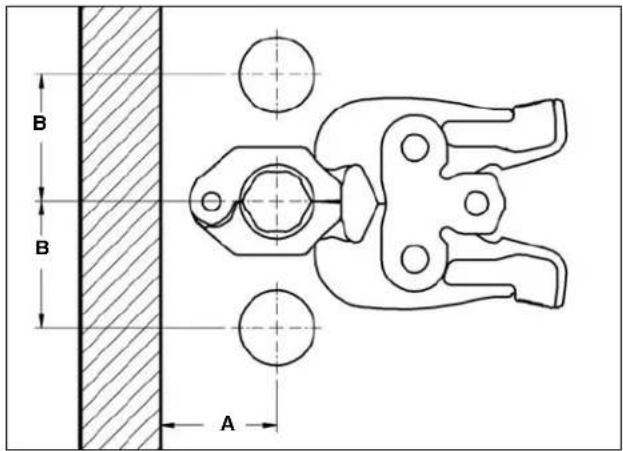
text_image
B B A| Tube Dia. | A (min.) B (min.) | |||
| Inches mm Inches mm | ||||
| ^1/_2 " | 1^5/_8 " | 41 | 2^12/_16 " | 71 |
| ^3/_4 " | 1^3/_4 " | 45 | 2^3/_16 " | 55 |
| 1" 2" 51 | 1 | ^3/_6 " 42 | ||
| 1^1/_4 " | 2^5/_16 " | 55 | 2^15/_16 " | 75 |
| 1^1/_2 " | 2^3/_8 " | 60 | 3^3/_16 " | 85 |
| 2" | 2^6/_16 " | 65 4 | ^1/_8 " | 105 |
text_image
A C B| Tube Dia. | A (mln.) B (mln.) C (mln.) | |||||
| Inches | mm Inches | mm Inches mm | ||||
| ^1/_2 " | 2^1/_6 " | 57 | 2^1/_6 " | 54 | 1^1/_16 " | 27 |
| ^3/_4 " | 2^1/_16 " | 68 | 2^1/_8 " | 73 1 | ^1/_8 " | 28 |
| 1" | 2^15/_18 " | 75 | 3^3/_10 " | 84 | 1^3/_16 " | 31 |
| 1^1/_4 " | 3^5/_18 " | 84 | 3^7/_10 " | 99 | 1^3/_16 " | 30 |
| 1^1/_2 " | 3^1/_18 " | 94 | 4^3/_10 " | 110 | 1^3/_16 " | 31 |
| 2" | 4^7/_18 " | 113 | 5^7/_10 " | 139 | 1^3/_16 " | 30 |

text_image
B C A| V1 | |||||||
| Tube Dia. | A (min.) B (min.) C (min.) | ||||||
| Inches mm Inches mm Inches mm | |||||||
| 1/2" | 1^5/_8" | 41 | 3 | ^9/_16" | 90 | 2 | ^5/_16" 59 |
| 3/4" | 1^3/_4" | 45 | 3 | ^5/_9" | 92 | 2 | ^1/_8" 55 |
| 1" 2" | 51 | 3 | ^13/_16" | 97 2 | ^3/_16" 56 | ||
| 1^1/_4" | 2^1/_16" | 55 | 3 | ^3/_4" | 92 | 2 | ^1/_8" 55 |
| V2 | |||||||
| Tube Dia. | A (min.) B (min.) C (min.) | ||||||
| Inches mm Inches mm Inches mm | |||||||
| 1^1/_2" | 2^3/_6" | 60 | 5" 127 | 2 | ^3/_19" 56 | ||
| 2" 2 | ^9/_16" | 65 | 4 | ^3/_4" | 121 2 | ^9/_18" 65 | |
| C1 | |||||||
| Tube Dia. | A (min.) B (min.) C (min.) | ||||||
| Inches mm Inches mm Inches mm | |||||||
| 1/2" | 1^5/_8" | 41 | 3 | ^1/_4" | 83 | 2" 51 | |
| 3/4" | 1^3/_4" | 45 | 3 | ^1/_4" | 83 | 1 | ^7/_8" 48 |
| 1" 2" | 51 | 3 | ^1/_4" | 83 | 1 | ^7/_8" 48 | |
| 1^1/_4" | 2^2/_16" | 55 | 3 | ^5/_9" | 86 | 1 | ^7/_8" 46 |
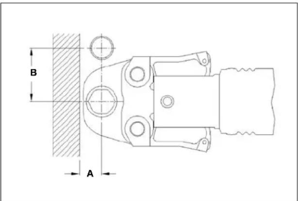
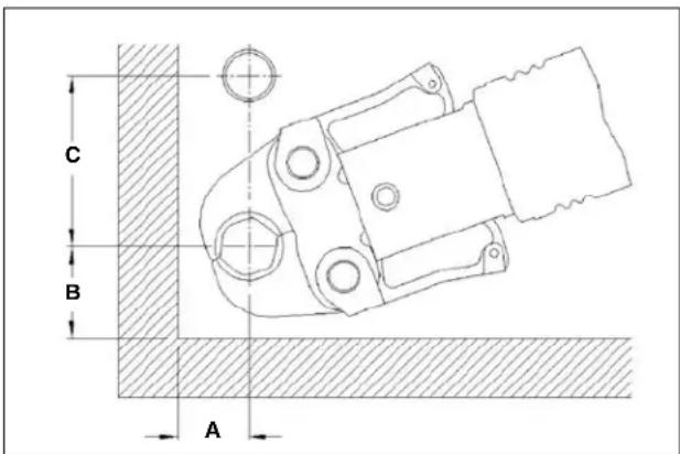
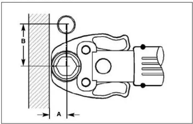
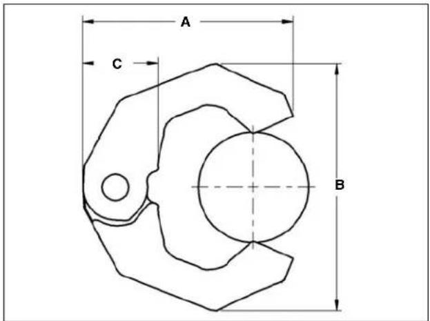
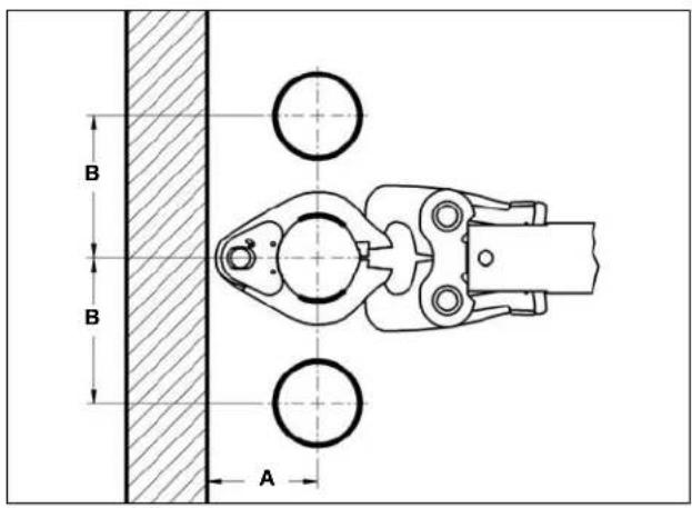
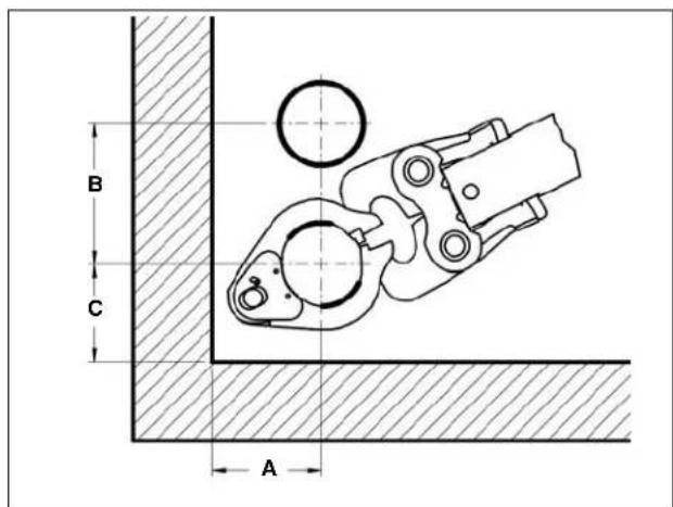
Clearance Requirements – ProPress XL-C Press Rings
text_image
B B A| Tube Dia. | A (min.) | B (min.) | ||
| Inches | mm | Inches | mm | |
| 2^1/2" | 4^1/_a" | 105 | 6" | 152 |
| 3" | 4^2/_a" | 111 | 7" | 178 |
| 4" | 5" | 127 | 8" | 203 |
text_image
B C A| Tube Dia. | A (mln.) B (mln.) C (mln.) | |||||
| Inches mm Inches mm Inches mm | ||||||
| 2^1/2" | 4^1/8" | 105 6" | 152 | 4 | ^1/_2" | 114 |
| 3" | 4^3/8" | 111 7" | 178 | 4 | ^7/_8" | 124 |
| 4" | 5" | 127 | 8" | 5^3/_4" | 146 | |
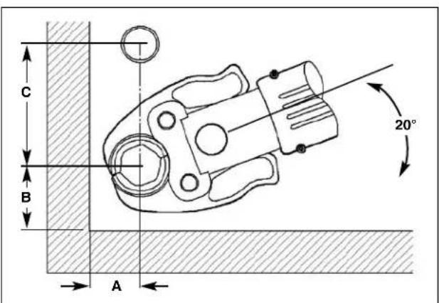
text_image
A C B| Tube Dia. | A (mln.) B (mln.) C (mln.) | ||||
| Inches | mm Inches | mm Inches mm | |||
| 2^1/_2 " | 6^3/_18 " | 157 6 | ^15/_16 " | 176 7 | ^7/_16 " 62 |
| 3" 7 | ^7/_18 " | 189 8 | ^13/_16 " | 224 2 | ^7/_16 " 62 |
| 4" 8 | ^7/_18 " | 205 10 | ^7/_16 " | 265 2 | ^7/_16 " 62 |
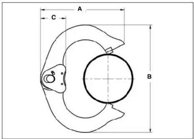
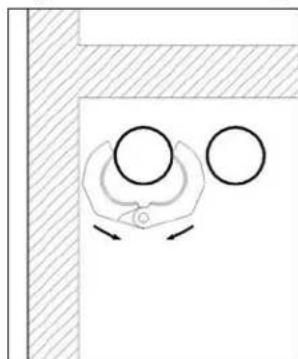
Tight Quarter Pressing Procedure – Pressing Rings
natural_image
Simple line drawing of a mechanical component with two circular holes and directional arrows, no text or symbols present.- Place the press ring around the fitting from the front...
natural_image
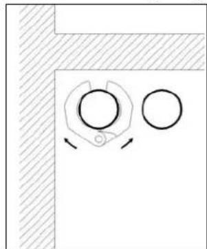
Simple diagram showing a circular object with directional arrows inside a rectangular frame, no text or symbols present.- ...until the press ring is resting in the groove of the fitting.
natural_image
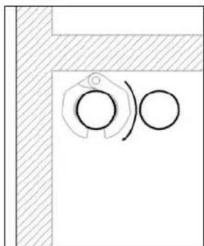
Pure technical diagram showing a circular component with two curved arrows, no text or symbols present.- Keep the press ring closed and rotate about the fitting until the opening is toward the front.
natural_image
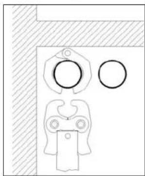
Simple line drawing of a person holding a device with circular elements, no text or symbols present- Insert the press ring actuator and start the press cycle.
Troubleshooting
| SYMPTOM POSSIBLE REASONS SOLUTION | ||
| Press connections produced are not complete. | Used wrong jaw set or press ring for the tube size or material.The jaw set or ring contour was not square to the tube.The jaw set or ring has exceed life expectations and may have failed. | Install correct jaw set.Redo the joint using new tube and fitting and make sure that the jaw set or ring is square to the fitting.If cracked, replace old jaw set with a new jaw set and redo the joint using new tube and fitting. |
| Excessively large or sharp fins present at press joint parting line where jaw or ring tips come together. | Fitting material build up on jaws or press rings in the contoured profile area near jaw or ring tips.Excessively worn or damaged jaws or press rings. | Clean jaw or press ring in the contoured area using metal polishing pads such as Scotch-Brite. Refer to Maintenance Section for instructions.Discard jaws or press ring and replace with new RIDGID jaw set or press ring. |
| Jaws or rings stick to fitting excessively after completing press joint. | Fitting material build-up on jaws or press ring in the contoured profile area near jaw or ring tips. | Clean jaw or press ring contour area using metal polishing pads such as Scotch-Brite. Refer to Maintenance Section for instructions. |
- ProPress
- ProPress XL-C
ProPress
natural_image
Row of black industrial crimping clips with no visible text or symbolsFigure 1 – Mâchoires ProPress série Standard
natural_image
Four black industrial clamping clips with visible metal fasteners and mounting holes (no text or symbols)natural_image
Two black industrial crimping tools: one with V2 and label 'RiDGD', the other with 2" and 2" labels (no text or symbols on the tools themselves)natural_image
Close-up of hands using a crimping tool to handle a cylindrical pipe (no visible text or symbols)natural_image
Side profile of a man wearing glasses and a suit, holding an object near his ear (no text or symbols visible)natural_image
Close-up of a hand holding a pen writing on a cylindrical object (no visible text or symbols)text_image
Close-up of a hand holding a metallic mechanical component with warning labels and safety symbolsnatural_image
Close-up of a mechanical clamp or bracket with metal fittings and bolts (no visible text or symbols)natural_image
Close-up of a mechanical component with a metallic shaft and flange, no visible text or symbolsnatural_image
Close-up of a mechanical component with a cylindrical shaft and flange (no visible text or symbols)natural_image
Close-up of a metallic pipe fitting with hexagonal end caps and flange (no visible text or symbols)natural_image
Close-up of a hand using a crimping tool to adjust a mechanical component (no visible text or symbols)natural_image
Close-up of a mechanical component with black and metallic parts, no visible text or symbolsnatural_image
Simple line drawing of a hand holding a circular object with directional arrows, no text or symbols presentnatural_image
Simple line drawing of a mechanical component with two circular holes and directional arrows, no text or symbols present.natural_image
Pure technical diagram showing two circular components inside a corner with hatched areas (no text or symbols)natural_image
Simple line drawing of a door with circular opening and handle, no text or symbols present- ProPress
- ProPress XL-C
ProPress
natural_image
Row of black industrial crimping clips with metallic fittings (no visible text or symbols)natural_image
Four black industrial clamping clips with visible metal fasteners and mounting holes (no text or symbols)natural_image
Two black RIGID mechanical clamp components, one with labeled V2 and the other with 'PROFRASS' and 'V2', shown against a white background (no text or symbols on the devices themselves)natural_image
Close-up of hands using a crimping tool to handle a cylindrical pipe (no visible text or symbols)natural_image
Side profile of a person wearing glasses, holding a small ring (no text or symbols visible)natural_image
Close-up of a hand holding a pen writing on a metallic pipe fitting (no visible text or symbols)text_image
Close-up of a hand holding a metallic mechanical component with warning labels and safety symbolsnatural_image
Close-up of a hand gripping a mechanical clamp or bracket (no visible text or symbols)natural_image
Close-up of a mechanical pipe fitting with a metallic shaft and clamping mechanism (no text or symbols visible)natural_image
Close-up of a mechanical component with a cylindrical shaft and flange (no visible text or symbols)natural_image
Close-up of a metallic pipe fitting with hexagonal end caps and central shaft (no visible text or symbols)natural_image
Close-up of a hand using a power tool to adjust a mechanical component (no visible text or symbols)natural_image
Close-up of a mechanical component with no visible text or symbolsnatural_image
Simple line drawing of a mechanical component with two circles and directional arrows, no text or symbols present.natural_image
Simple diagram showing a circular component with two circles inside a corner, no text or symbols present.natural_image
Pure technical diagram showing a corner joint with two circular features and a curved arrow, no text or symbols present.natural_image
Simple line drawing of a mechanical device with circular components and a handle, set against a hatched background (no text or symbols)RIDGID ^® tools are warranted to be free of defects in workmanship and material.
How long coverage lasts
This warranty lasts for the lifetime of the RIDGID tool. Warranty coverage ends when the product becomes unusable for reasons other than defects in workmanship or material.
How you can get service
To obtain the benefit of this warranty, deliver via prepaid transportation the complete product to RIDGE TOOL COMPANY, Elyria, Ohio, or any authorized RIDGIONDEPENDENT SERVICE CENTER. Pipe wrenches and other hand tools should be returned to the place of purchase.
What we will do to correct problems
Warranted products will be repaired or replaced, at RIDGE TOOL'S option, and returned at no charge; or, if after three attempts to repair or replace during the warranty period the product is still defective, you can elect to receive a full refund of your purchase price.
What is not covered
Failures due to misuse, abuse or normal wear and tear are not covered by this warranty. RIDGE TOOL shall not be responsible for any incidental or consequential damages.
How local law relates to the warranty
Some states do not allow the exclusion or limitation of incidental or consequential damages, so the above limitation or exclusion may not apply to you. This warranty gives you specific rights, and you may also have other rights, which vary, from state to state, province to province, or country to country.
No other express warranty applies
This FULL LIFETIME WARRANTY is the sole and exclusive warranty for RIDGID ^3 products. No employee, agent, dealer, or other person is authorized to alter this warranty or make any other warranty on behalf of the RIDGE TOOL COMPANY.

text_image
RIDGID FULL LIFETIME WARRANTY Against Material Defects & WorkmanshipParts are available online at RIDGIDParts.com

Ridge Tool Company
400 Clark Street
Elyria, Ohio 44035-6001
U.S.A.