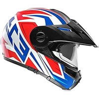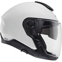
J2 - Motorcycle helmet Schuberth - Free user manual and instructions
Find the device manual for free J2 Schuberth in PDF.


User questions about J2 Schuberth
0 question about this device. Answer the ones you know or ask your own.
Ask a new question about this device
Download the instructions for your Motorcycle helmet in PDF format for free! Find your manual J2 - Schuberth and take your electronic device back in hand. On this page are published all the documents necessary for the use of your device. J2 by Schuberth.
USER MANUAL J2 Schuberth
natural_image
Front view of a white and black HUBERTH motor helmet with clear visor and red buttons (no text or symbols on the helmet itself)J2
natural_image
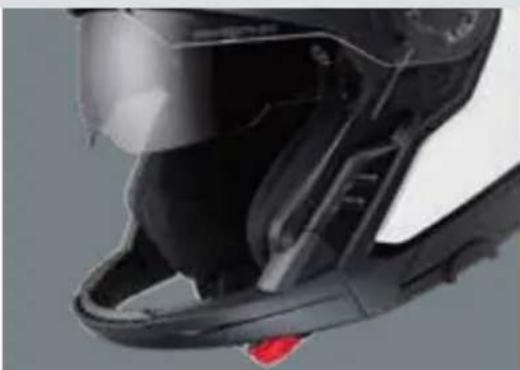
Close-up of a black helmet with clear visor and red button (no text or symbols visible)
SCHUBERTH
MANUAL
J2
4 - 51
52–97
106 - 156
158 - 206
208 - 256
DE
EN
FR
IT
ES
J2
text_image
Diagram illustrating hand positioning and movement of a curved object with labeled arrows 1, 2, and directional arrows.Tipp:
natural_image
Technical line drawing of a mechanical component with a magnified inset showing a detail (no text or symbols)Achtung:
text_image
Diagram illustrating a medical procedure on a helmet with labeled steps and magnified detail view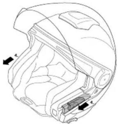
text_image
Technical diagram of a helmet with labeled parts and directional arrows indicating movement or assembly.ARRETIEREN DES KINNTEILS
text_image
Diagram illustrating a medical procedure on a helmet with labeled steps and an inset showing the insertion of the component.C. DER HELM
natural_image
Technical line drawing of a helmet component with labeled parts (no text or symbols present)Achtung:
natural_image
Illustration of two types of cable or clamp accessories with directional arrows indicating movement (no text or symbols)Tipp:
text_image
Diagram illustrating three-step instructions for handling a tool, labeled (1) and (2), with arrows indicating movement.⚠️ Warnung:
natural_image
Illustration of a person wearing a helmet with an arrow pointing to the nose area (no text or symbols present)C. DER HELM
SCHLIESSEN DES VISIERS
natural_image
Illustration of a person in a helmet with hand gesture, no text or symbols presentDE
VISIERWECHSEL
natural_image
Diagram of hands operating a mechanical device with a rotating arrow indicating rotation (no text or symbols present)natural_image
Illustration of hands operating a device with an arrow indicating direction, showing internal components and a magnified inset (no text or symbols)C. DER HELM
ANTIBESCHLAG-SCHEIBE (OPTIONAL)
Ausbau
natural_image
Illustration of hands holding a bandage with labeled clips (no text or symbols present)C. DER HELM
natural_image
Illustration of hands using a tool to adjust or install a small object, with a magnified inset showing a face highlighting the area (no text or symbols present)Einbau
natural_image
Illustration of a hand holding a leaf with magnified inset showing internal structure (no text or symbols)natural_image
Diagram showing a hand holding a small object with an inset magnified view of a mechanical component (no text or symbols)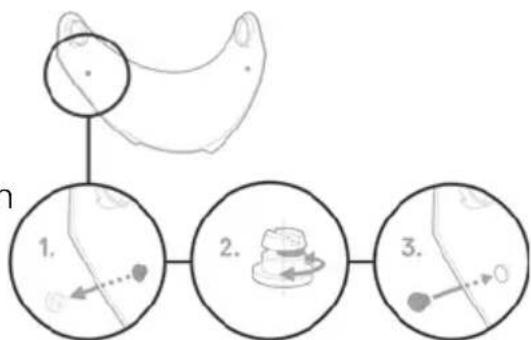
flowchart
graph TD
    A["Bed with mouse"] --> B["1. Table with mouse icon"]
    B --> C["2. Table with cake icon"]
    C --> D["3. Table with mouse icon"]
    style A fill:#f9f,stroke:#333
    style B fill:#ccf,stroke:#333
    style C fill:#cfc,stroke:#333
    style D fill:#fcc,stroke:#333
Hinweise:
natural_image
Technical line drawing of a helmet with directional arrows indicating movement or force (no text or symbols)natural_image
Line drawing of a motorcycle helmet showing front and side views with no text or symbolsAchtung:
natural_image
Line drawing of a hand pressing down on a car wheel (no text or symbols)C. DER HELM
natural_image
Technical line drawing of a mechanical component with no visible text or symbolsSonnenblende-Einbau
natural_image
Diagram of a hand holding a device with two arrows indicating movement or force (no text or symbols present)natural_image
Illustration of a hand using a tool to adjust or install a mechanical component, with arrows indicating the process (no text or symbols present)natural_image
Hand pressing a button on a car intake manifold (no text or symbols visible)C. DER HELM
natural_image
Line drawing of a hand pressing down on a mechanical component (no text or symbols)C. DER HELM
natural_image
Illustration of a hand gripping a helmet (no text or symbols)AUSBAU WANGENPOLSTER
natural_image
Line drawing of hands using a tool to adjust or install a mechanical component (no text or symbols visible)C. DER HELM
AUSBAU KOPFPOLSTER
natural_image
Anatomical illustration of a human head and neck region with arrows indicating specific areas (no text or labels present)DE
natural_image
Illustration of a hand holding a leaf with a small flower, enclosed in a circular frame (no text or symbols)natural_image
Diagram of a hand holding a car wheel, showing the wheel and seat area (no text or labels)natural_image
Technical line drawing of a mechanical component or bracket (no text or symbols)natural_image
Anatomical illustration of a human head and neck region, showing internal structures without any text or labels.natural_image
Diagram of a car interior showing directional arrows indicating movement or flow (no text or symbols present)natural_image
Line drawing of a hand holding a medical device with a shaded grip, no text or symbols present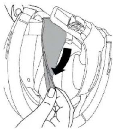
natural_image
Line drawing of a hand holding a tool interacting with a device component, showing a black arrow indicating direction (no text or symbols present)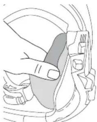
natural_image
Illustration of a hand adjusting a car seatbelt (no text or symbols)C. DER HELM
natural_image
Illustration of a hand inserting a cable into a car seatbelt (no text or symbols)Achtung:
natural_image
Illustration of a person in protective gear adjusting a helmet with an arrow (no text or symbols)natural_image
Anatomical line drawing of a pelvic region with no visible text or labels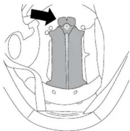
natural_image
Diagram of a mechanical component with an arrow indicating direction, no visible text or symbolsC. DER HELM
natural_image
Side profile illustration of a helmet with shaded top and front blade (no text or symbols)natural_image
Line drawing of a hand holding a tool above a helmet component (no text or symbols)5. VERSCHLUSSSYSTEM
text_image
QR code image with a central circular logo, likely linking to a digital resource or website.natural_image
Line drawing of a helmet with an inset close-up showing a hand holding a camera lens (no text or symbols)text_image
QR code image with a central circular logo, likely linking to a digital resource or website.Tipp:
natural_image
Symbol of a trash bin with crossed lines indicating no waste, and a solid black rectangle below (no text or labels)In our decades of experience in the development and manufacture of motorcycle helmets. We're delighted that you have chosen the SCHUBERTH J2. Every single J2 that leaves our factory has been made with exquisite craftsmanship using state-of-the-art manufacturing techniques.
The J2 features outstanding aeroacoustics and advanced ergonomics. Perfected in our wind tunnel, the aerodynamics ensure stable helmet performance at all times. Of course, the J2 has the proven features of a SCHUBERTH helmet in terms of safety, comfort and design that you can expect. All these features, our high standards for the quality of the materials used, as well as our meticulous craftsmanship, go together to make a quality product designed to meet extremely high expectations in safety and reliability on the road and off-road—especially on long journeys. The interior, with its exclusive seamless linings and thanks to the SCHUBERTH individual program offers an unparalleled comfort level.
We hope you enjoy your SCHUBERTH J2 and wish you a safe ride.
A. HOW TO USE THIS MANUAL CORRECTLY
Please take time to read through this manual carefully so that your helmet protects you properly when riding your motorcycle. In order to ensure that you do not overlook any aspect of the manual that is relevant to your safety, we recommend that you read it in the order in which it appears.
Please pay particular attention to:
Caution: safety instructions
Note: advice
√ Tip: practical tips
Caution:
This helmet is not intended for use in the United States of America. The helmet has been inspected and approved to the European ECE Standard, therefore it does not comply to US regulations and requirements. It is only legal to use the helmet in countries in which the European ECE Standard is valid. Use in other countries does not entitle the user to make claims for compensation in the event of damage before the US courts or the courts of other countries not bound by the ECE Standard.
Caution:
We reserve the right to make changes that reflect technical advances and to do so without express notice.
B. CONTENTS
A. HOW TO USE THE MANUAL CORRECTLY ____ 52
B. CONTENTS 53
C. THE HELMET 55
- Standard 55
- ECE approval 55
- Anatomy of the helmet 56
- Helmet shell 57
- Inner shell 57
- Aerodynamics and Aeroacoustics 57
- Additional wind deflector 59
- Chin bar 59
- Chinstrap with Micro-Lock ratchet fastener 61
- Visor with anti-fog lens 63
- Sun visor 68
- Inner lining 71
- Ventilation systems 77
- Additional safety features 78
D. PUTTING ON THE HELMET AND TAKING IT OFF 79
-
Putting on the helmet 79
-
Taking off the helmet 79
E. BEFORE EVERY JOURNEY 80
- Checking the helmet 80
- Checking the chinstrap 80
- Checking the visor and sun visor 80
- Checking the chin bar 81
B. CONTENTS
F. FOR YOUR SAFETY 82
- Safety advice concerning the helmet 82
- Safety advice concerning the visor / sun visor 83
- Safety advice concerning modifications / accessories 84
G. MAINTENANCE AND CARE 85
- Helmet shell 85
- Visor and sun visor 85
- Inner lining 86
- Ventilation 86
- Retention system 88
- Storing the helmet 88
H. ACCESSORIES AND SPARE PARTS 89
- Communication system 89
- SCHUBERTH individual program 90
- Accessories and spare parts 91
- Ordering original SCHUBERTH parts 91
I. SCHUBERTH SERVICE 92
J. WARRANTY 93
K. ENVIRONMENTAL PROTECTION 94
L. HOW TO CONTACT US 95
C. THE HELMET
1. STANDARD
The J2 conforms to the ECE-R 22.06 standard. This testing norm guarantees conformity to defined safety standards in respect of shock absorption, visor, retention system and field of vision. The certification applies to all the countries of the European Union and all countries that recognise the ECE standard. It also guarantees conformity with all insurance requirements that are important in the event of a claim.
Please note that this J2 with ECE approval is not certified for the United States of America. It is only permitted for use in countries where the ECE standard is valid.
Note:
The only SCHUBERTH helmets that are legal to use in the United States of America are those with the appropriate approval and technical specifications. Further information and details of sales outlets for these helmets can be found on the internet at:
WWW.SCHUBERTH.COM
2. ECE-APPROVAL
Helmet
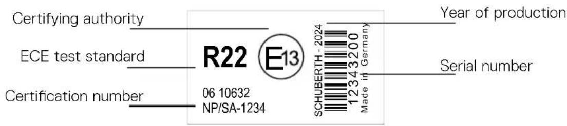
text_image
Certifying authority ECE test standard Certification number R22 E13 06 10632 NP/SA-1234 Year of production SCHUBERTH - 2024 Made in Germany 1234 3200 Serial numberVisor
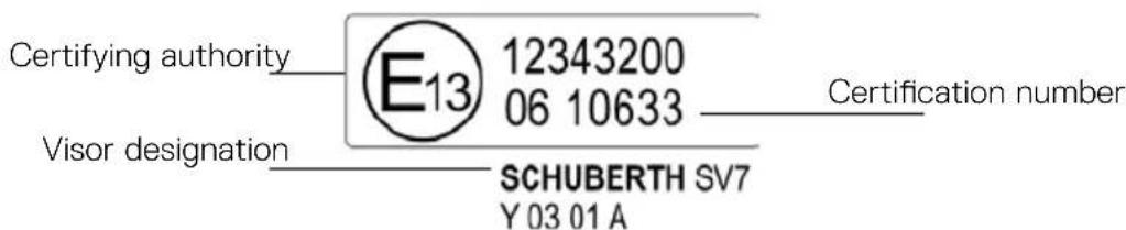
text_image
Certifying authority E13 12343200 06 10633 Visor designation SCHUBERTH SV7 Y 03 01 A Certification numberC. THE HELMET
The following visors are approved for the SCHUBERTH J2:
Visor
clear,
dark smoke, SV7/D
Designation according to the approval
SV7/C
Communication systems
The J2 is supplied with pre-instelled speakers, wiring harness and antennas.
The following communication systems are approved for the J2:
- SC2
- SC2 Standard
- SC Edge
3. ANATOMY OF THE HELMET
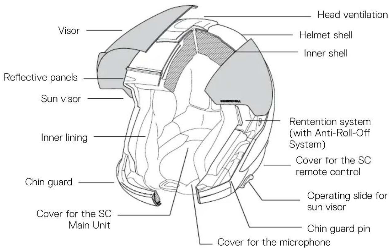
text_image
Head ventilation Helmet shell Inner shell Visor Reflective panels Sun visor Inner lining Rentention system (with Anti-Roll-Off System) Cover for the SC remote control Chin guard Operating slide for sun visor Chin guard pin Cover for the microphone Cover for the SC Main UnitC. THE HELMET
4. HELMET SHELL
The helmet shell of the J2 combines an aerodynamically optimal shape with consistent protection. It consists of a new fiberglass shell from our patented Direct Fiber Technology reinforced with carbon fiber for improved shock absorption strength and lighter weight.
Caution:
The helmet is a safety device designed to absorb the effects of only one impact. The helmet have to be replaced after a fall, accident or any other impact.
5. INNER SHELL
For optimised shock absorption properties, the inner shell of the helmet consists of new EPS material. The complex multi-segment foam padding of the main body provides better absorption and dissipation of impact forces and gives you the highest level of safety. The large side panels ensure the helmet fit optimally and comfortably.
6. AERODYNAMICS AND AEROACOUSTICS
The J2 produces practically no uplift even at speed, Various features developed in SCHUBERTH's wind tunnel make the helmet notably quiet as far as aeroacoustics are concerned, while providing optimized hearing capability when riding. This enhances concentration, especially at high speeds.
Note:
Aeroacoustics values may vary according to the type of motorcycle, fairing design, seat position and physical size of the rider.
Caution:
As a result of the aeroacoustics optimization of the helmet (and the lower wind noise inside the helmet that comes with it), your actual speed can easily be underestimated. Please do not rely on your sense of hearing to estimate your road speed - always check it using your speedometer.
C. THE HELMET
Note:
With faired motorcycles, strong currents occur at the edges of the wind shadow. These may significantly reduce the aeroacoustic performance of the helmet. The motorcycle fairing should be adjusted so that the turbulence created does not reach the bottom surface of the helmet.
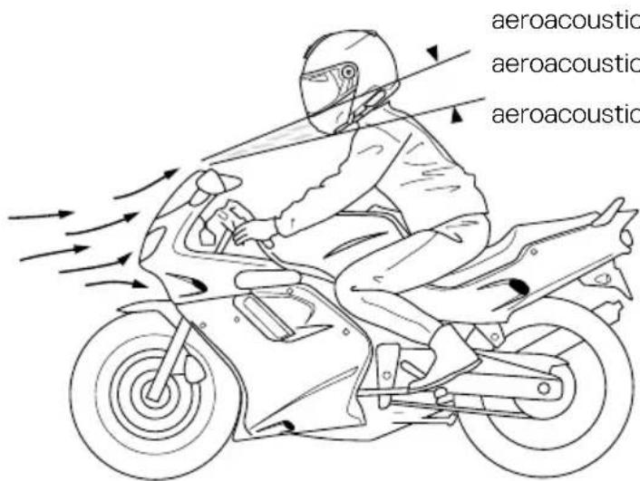
text_image
aeroacoustic aeroacoustic aeroacousticaeroacoustically non-critical area aeroacoustically critical area aeroacoustically non-critical area
Turbulators
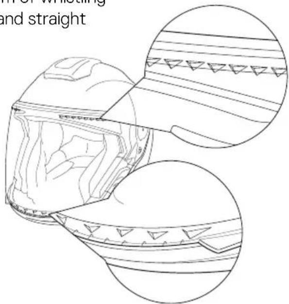
The patented turbulators on the top and on the bottom of the visor also optimise the aeroacoustic properties when riding and prevent acoustic disturbances in the form of whistling sounds that can be created by smooth and straight edges.
text_image
M. of Wristling and straightC. THE HELMET
7. ADDITIONAL WIND DEFLECTOR
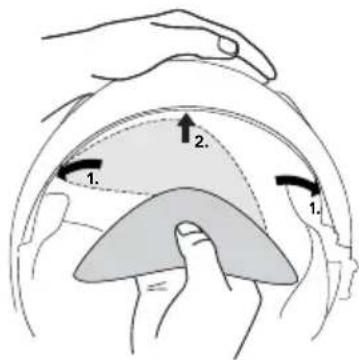
The additional wind deflector prevents the unpleasant effect of the wind created as you ride flowing into the helmet. In addition, the riding noise in the helmet is reduced.
The wind deflector is included in the box and is ready to be installed. To install it, first position it in the corners, then secure it in the middle.
text_image
Diagram illustrating hand positioning of a helmet with labeled parts and directional arrows indicating movement or positioning.Tip:
The fit of the bottom of the helmet is extremely important in ensuring that the helmet is as quiet as possible. If you have a smaller neck size, we recommend that you also wear a scarf.
8. CHIN BAR
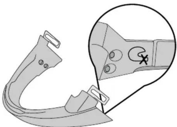
The J2 is equipped with a chin bar that has been designed for easy installation and removal. This flexibility allows you to add or remove the guard as needed, ensuring optimal comfort and functionality
natural_image
Technical line drawing of a mechanical component with a magnified inset showing internal features (no text or symbols)Note:
Does not protect chin from impacts.
C. THE HELMET
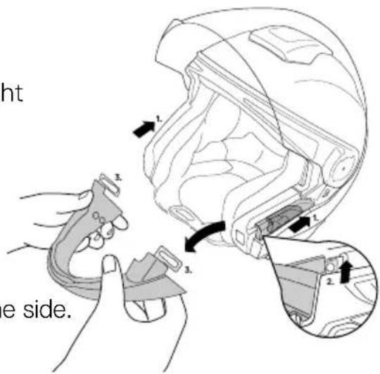
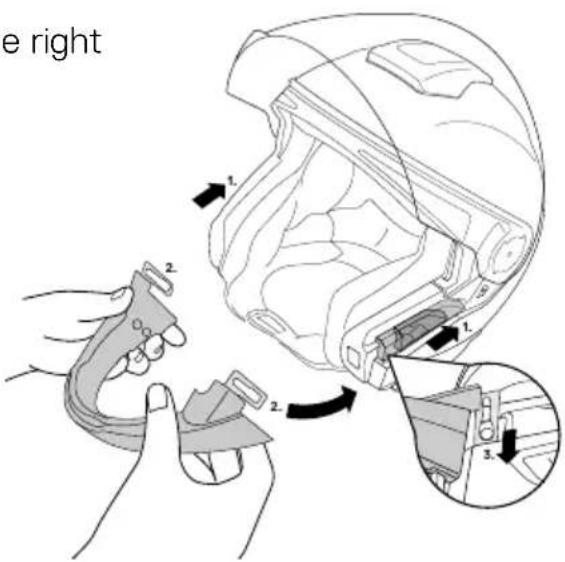
DETACHING THE CHIN BAR
-
Slide the cover on the left and on the right to the back.
-
Lift the chin bar upwards.
-
Remove the brackets from the pin on one side. Repeat the operation on the other side
-
Slide the sliders back to the front.
text_image
ht e side.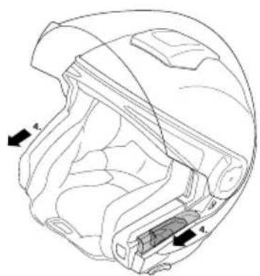
natural_image
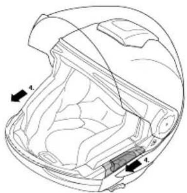
Technical line drawing of a helmet with labeled components (no text or symbols present)INSTALLING THE CHIN BAR
-
Slide the slider on the left and on the right to the back.
-
Place the bracket over the pin on one side. Repeat the operation on the other side
-
Push the chin bar downwards.
text_image
e right 1. 2. 3.C. THE HELMET
- Slide the slider back to the front.
natural_image
Technical line drawing of a mechanical component with labeled parts (no text or symbols present)EN
Note:
Each time you install the chin bar, check that it's securely fitted by pushing the chin bar upwards.
9. CHINSTRAP WITH MICRO-LOCK RATCHET FASTENERS
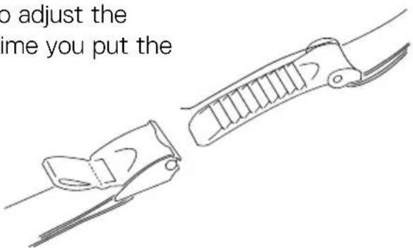
The J2 is fitted with a ratchet strap. This locking system is easy to use and enables you to adjust the chinstrap perfectly to your head every time you put the helmet on.
text_image
to adjust the time you put theADJUSTING THE CHINSTRAP
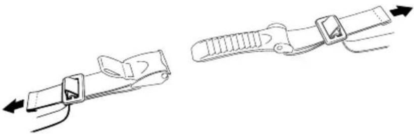
The length of the chinstrap can be adjusted by increasing or reducing the length of strap pulled through the metal buckles. Adjust the length of the chinstrap so that it fits firmly but comfortably under your chin.
natural_image
Two line drawings of a cable clamp device, one with a loop and arrow indicator, the other with a handle and arrow indicator (no text or symbols)C. THE HELMET
Tip:
Both chin straps are adjustable in length.
Caution:
When adjusting the strap, make sure that the helmet cannot be pulled off in a forward direction with the chinstrap closed.
Caution:
Check the adjustment of the chinstrap length at regular intervals. Opening and closing
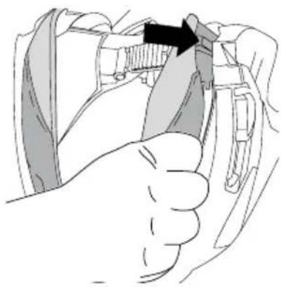
To close the chinstrap fastener, slide the ratchet tongue step by step into the locking buckle. If you find that the chinstrap fits too loosely around your chin, slide the ratchet tongue one step further into the locking buckle. When adjusting the chinstrap, make sure that it rests firmly but not uncomfortably around your chin. To open the chinstrap, pull the red ribbon on the ratchet fastener upwards to release the locking buckle (1). Then pull the ratchet tongue out of the locking buckle (2).

text_image
Illustration showing three-step instructions for handling a tool, labeled (1) and (2), with arrows indicating movement.Caution:
Never ride without making sure that the chinstrap is correctly fastened and adjusted and properly positioned. If the chinstrap is not correctly adjusted or fastened, the helmet could be displaced in the event of an accident.
Caution:
Never open the chinstrap while riding.
C. THE HELMET
10. VISOR WITH ANTI-FOG LENS (OPTIONAL)
The visor is a fog-free double-lens visor. By fixing the inner anti-fog lens using eccentric pins, the two visor panes are pre-tensioned together and are thereby sealed. An insulating air cushion is thus formed between the visor's main plate – i.e. the outer plate – and the inner plate, which prevents any fogging up of the inner plate.
COATING
The main visor has an anti-scratch coating.
Note:
The helmet should never be used to hold gloves or any other objects as this may damage the scratch-sensitive anti-fog lens.
Note:
The anti-fog lens is supplied with a protective film. Remove this film before using the helmet for the first time.
Note:
The visor is supplied with a protective foil. Remove this foil before using the helmet for the first time.
OPENING THE VISOR
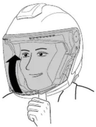
To open the visor, use your thumb to push the visor up using one of the finger tabs situated to the left and right of the visor, and move it to the desired position.
natural_image
Illustration of a person wearing a full-body helmet with an arrow indicating direction (no text or symbols)C. THE HELMET
CLOSING THE VISOR
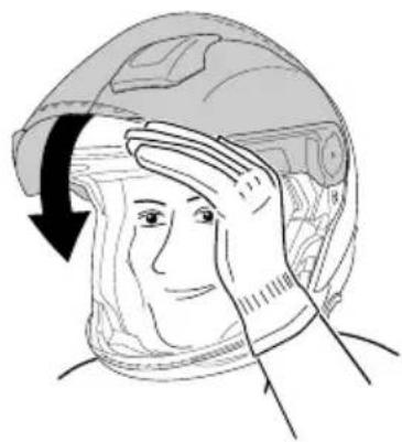
To close the visor, grip the finger tabs at top left and right and press the visor down with one movement.
natural_image
Illustration of a person in a helmet with hand gesture, showing head and torso positioning (no text or symbols)REPLACING THE VISOR
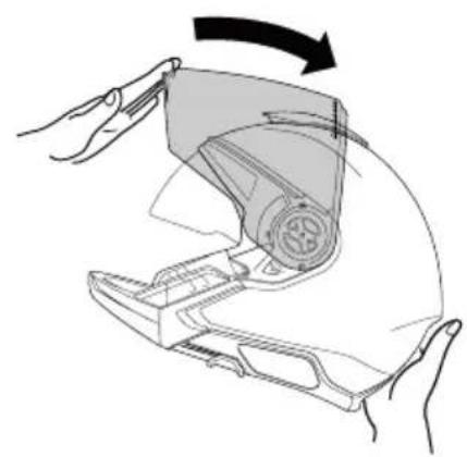
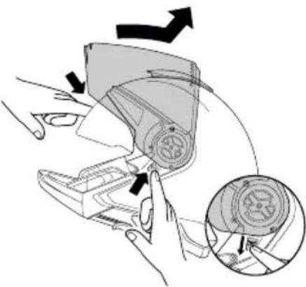
Changing the visor is easy to do without tools using the convenient EasyChange mechanism. To replace the visor, it is helpful to place the helmet on a flat surface or on your lap while seated.
Removing the visor
- Move the visor into the highest position.
natural_image
Diagram of a robotic device with hands operating it, showing a mechanical component and rotation arrow (no text or symbols)- Operate the spring elements on the right and left below the visor mechanism down.
natural_image
Illustration of a hand holding a device with an arrow indicating direction, showing internal components and a magnified inset (no text or symbols)^2 Move the visor up until it is released from the visor mechanism.
C. THE HELMET
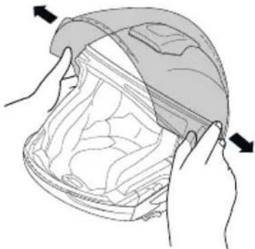
- Remove the visor by releasing it from the clamping mechanism and lifting it up.
natural_image
Illustration of hands holding a helmet with arrows indicating movement or force (no text or symbols)EN
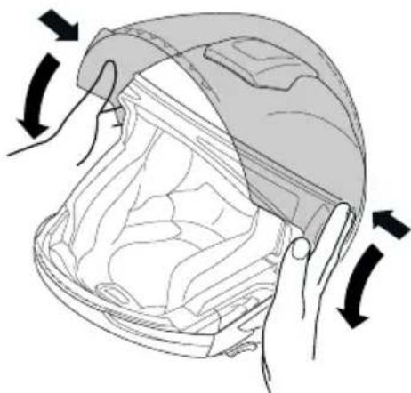
Installing the visor
-
Using both hands, guide the visor locking studs into the respective recesses in the visor mechanism.
-
The visor will then audibly lock into place when you press it gently towards the helmet with a simultaneous closing movement.
natural_image
Illustration of a person's helmet with arrows indicating motion or force (no text or symbols)ANTI-FOG LENS
(OPTIONAL)
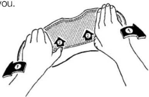
Removal
-
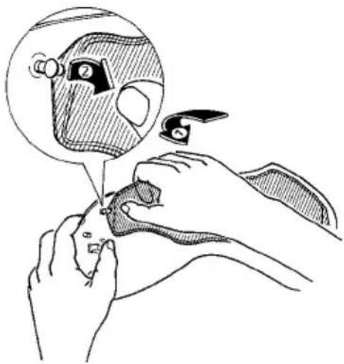
Before starting to remove the antifog lens, first lay the visor on a soft, clean cloth so that its top edge is facing you.
-
To reduce the pretensioning of the antifog lens slightly if necessary, use the balls of your thumbs to carefully bend the visor sufficiently apart while applying pressure with your thumbs to release the anti-fog lens and move it approx. 2–3 mm forward.
natural_image
Illustration of hands performing a bandage or motion capture task with labeled clips (no text or symbols present)C. THE HELMET
-
Now grip the back of the anti-fog lens with your index and middle fingers and lift it off the visor. In this position you can easily remove the anti-fog lens from the locking pin with your thumb.
-
You can now remove the anti-fog lens from the visor.
natural_image
Illustration of hands using a tool to adjust or install a face mask, with a magnified inset showing the mask detail (no text or symbols present)Fitting
-
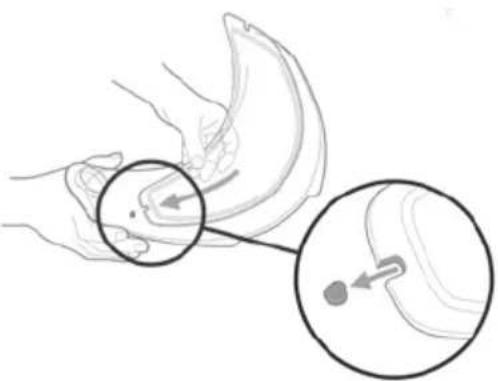
Remove the visor from the helmet.
-
Use the notch to help position one side of the anti-fog lens on one of the eccentric holding pins. Make sure that the silicone seal is facing the visor.
-
Carefully bend the visor just enough that the notch is guided onto the other eccentric holding pin on the opposite side of the anti-fog lens. To do this, you will need to bend the end of the anti-fog lens into a slight S-shape.
natural_image
Illustration of a hand holding a banana with a magnified inset showing the interior area of the fruit (no text or symbols)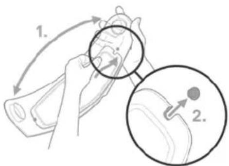
text_image
1. 2.C. THE HELMET
- Checking the correct application of the anti-fog lens, by trying to slide a piece of paper between the visor and the anti-fog lens. In case it gets between the two, please adjusting the pins in order to increase the strain of the anti-fog lens.,

text_image
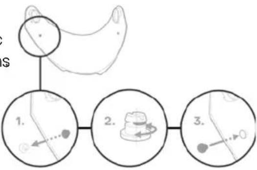
EN- In case of needs, it is possible to regulate the pressure on the seal by adjusting the eccentric locking-pins. To do so, remove the anti-fog lens then use a flat object with no sharp-edges to push the locking pins out of the visor carefully from the inside; then rotate them by 180^ and reinsert them. Fit the anti-fog lens and check the seal.
flowchart
graph TD
    A["Start"] --> B["Step 1: Left loop"]
    B --> C["Step 2: Right loop with rotation arrow"]
    C --> D["Step 3: Right loop with motion arrow"]
Note:
To avoid scratching the visor, never remove or fit the anti-fog lens unless the visor unit is clean and dry.
When fitting the anti-fog lens, check that neither dust nor moisture are able to get between the two surfaces.
When removing or fitting the anti-fog lens, it is always best to lay the visor unit on a clean, dry cloth.
Note:
In view of the strong air pressure acting when travelling with an open visor, we recommend riding with a closed visor at all times to prevent any dirt or moisture from getting inside the helmet.
Note:
To push out the locking pins, use a flat object with no sharp-edges.
C. THE HELMET
Caution:
As a result of the double lens structure, there is a possibility of greater light reflection in the face schield, especially when riding at night. As a rule, such light reflection is regarded as uncritical due to the absence of fog with this type of visor. However, if this light reflection should cause you difficulties – because of particular sensitivity to it, for example – you should refrain from using the anti-fog lens.
Caution:
If moisture is present in or has penetrated the airtight area between the two plates, you should remove the anti-fog lens immediately in order to prevent any interference with visibility. Do not re-fit it until both plates are completely dry (we recommend air-drying). If you should subsequently detect any further penetration of moisture, the anti-fog lens should not be used on any account and must be replaced.
Safety note
Check before each journey that the visor and sun visor mechanism are functioning correctly and that the visor and sun visor will provide good visibility. Any dirt should be removed before setting off. Check the visor and sun visor for physical damage and cracks. Severely scratched or scuffed visors will seriously impair visibility and should be replaced before setting off on a journey.
Caution:
Petrol, solvent and fuel vapors can cause cracking of the visor. Make sure that the visor is never exposed to such vapors! Never place the helmet on the tank of your bike.
11. SUN VISOR
SUN VISOR
The sun visor has a scratch-resistant coating and uses a special polycarbonate to ensure effective protection against harmful UV radiation.
C. THE HELMET
Operation
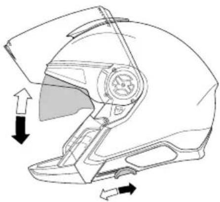
The sun visor is operated by means of the slide positioned on the left in the chin area, which is easy to use even when wearing gloves. Moving the slide towards the back lowers the sun visor, moving it forwards retracts the sun visor inside the inner helmet shell and locks it in position.
The sun visor can be operated irrespective of the position of the visor.
natural_image
Technical line drawing of a helmet with directional arrows indicating movement or force (no text or symbols)EN
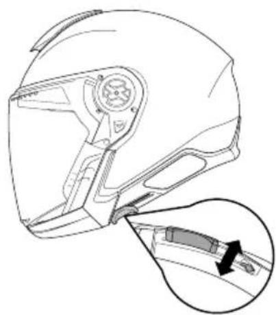
The maximum opening position of the sun visor can be set using the limiter. The limiter is on the running edge of the sun visor slider.
natural_image
Technical line drawing of a helmet component with an inset showing a close-up of the handle (no text or symbols)Note:
Only use the slide to operate the sun visor.
Caution:
Never ride in the dark or in conditions of poor visibility with the sun visor down. Always raise the sun visor before entering a tunnel.
Caution:
Riding without the visor or with an open visor can result in injury to the eyes and face from stones, dust, insects and other flying objects. The sun visor, when lowered, will offer a certain amount of protection from light impact from stones or insects but does not provide protection against all hazards.
C. THE HELMET
REPLACING THE SUN VISOR
The sun visor can be replaced without tools.
√ Tip:
To avoid fingerprints and scratches, use a soft, clean cloth (we recommend a microfibre cloth) to hold the sun visor when removing or installing it.
√ Tip:
Changing the sun visor is easier if you place the helmet on a flat surface or on your lap while seated.
Note:
Try to prevent the sun visor coming into contact with the helmet's inner shell when removing or fitting it.
Removing the sun visor
-
Open the visor.
-
Pivot the sun visor down.
-
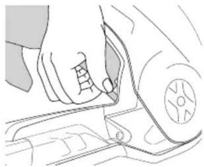
Hold the sun visor with one hand and press the latch backwards until it disengages. Repeat this step on the other side.
-
Press the retaining element inwards out of the sun visor. Repeat this step on the other side.
-
Move the slider of the sun visor slightly forward.
-
Press the sun visor inwards on both sides and remove it downwards.
natural_image
Line drawing of a hand using a tool to adjust or install a vehicle component (no text or symbols visible)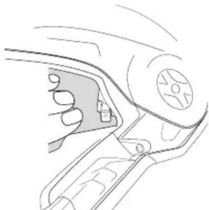
natural_image
Line drawing of a hand holding a device with a handle and control panel (no text or symbols)C. THE HELMET
Fitting the sun visor
- Bring the slider of the sun visor to the three-quarter position.
2.Slide the sun visor behind the the latch. Repeat this step on the other side. - Hold the sun visor with one hand and with the other hand push the slider backwards.
- Press the latch forward with your fingers until it clicks into place. Repeat this step on the other side.
- To be on the safe side, make a functional check of the sun visor operating mechanism.
natural_image
Line drawing of a person's seatbelt with arrows indicating movement or force (no text or symbols)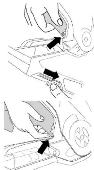
natural_image
Diagram showing two steps of a car wheel switch mechanism, with arrows indicating the process (no text or symbols present)12. INNER LINING
The interchangeable, washable and seamless inner linings of the J2 ensures a secure and comfortable fit, as well as improved helmet ventilation.
The high-comfort cheek pads ensure that the helmet fits comfortably around the cheeks, and the head pad provides an optimal fit all around the head. The head pad sits comfortably on the head without covering the ventilation channels.
C. THE HELMET
The internal lining consists of skin-friendly materials throughout, particularly in areas that come in contact with the head. A soft, breathable material known as Interpower®, which is fast-drying and conducts heat efficiently is used for the padding, as well as a special anti-bacterial low-odour fabric.
Thanks to the new SCHUBERTH individual program you have the possibility to optimize the fit of the helmet to increase comfort. For this purpose, we offer different head and cheek pads. For more information please visit our website www.schuberth.com.
REMOVING THE INNER LINING
Removing the neckroll
- Open the visor.
-
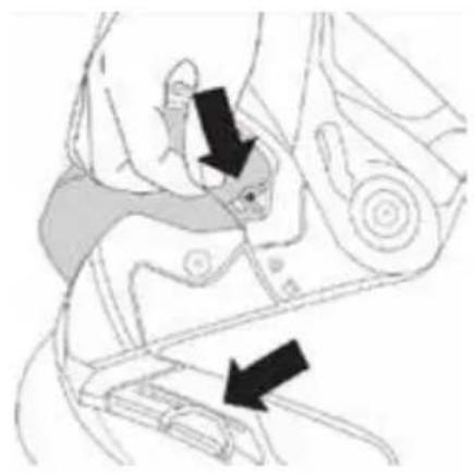
Undo the plastic hooks on the front tabs of the neckroll. To do this, pull the cheek pad slightly inside and press the end of the neckroll upwards.
-
Repeat step 2 on the other side.
-
Grasp one side of the neckroll and pull it backwards until the neckroll is released from the fixation.
-
Loosen the piping completely and pull it out of the fixation on the other side as well.
natural_image
Line drawing of a hand pressing down on a mechanical component (no text or symbols)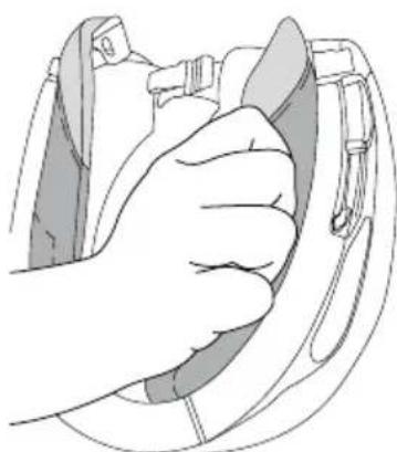
natural_image
Illustration of a hand gripping a helmet and buckle (no text or symbols)C. THE HELMET
Removing the cheek pad
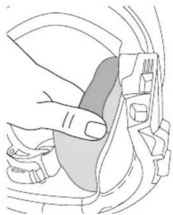
- Open the chin strap.
- Loosen the cheek pads by pulling the three pins out of the corresponding plug-in devices.
- Loosen the velcro connection to the head pad.
- Open the velcro fastener.
- Pull the chin strap out of the the cheek pad pocket and remove the cheek pad.
- Repeat step 2 to 5 for the removal of the cheek pad on the other side.
Removing the head pad
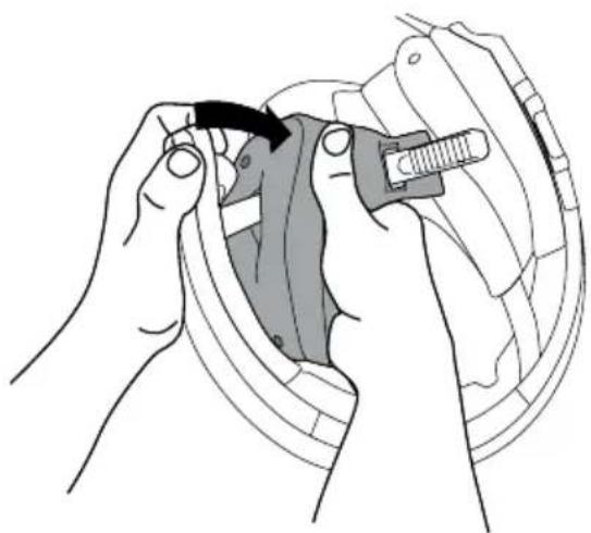
- Loosen the pins of the forehead padding and pull it out of the 4 holders.
natural_image
Illustration of hands using a tool to adjust or install a mechanical component, no text or symbols present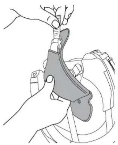
natural_image
Illustration of a hand using a tool to adjust or install a mechanical component (no text or symbols visible)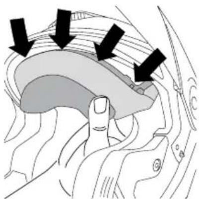
natural_image
Anatomical illustration of a brain with black arrows indicating specific regions (no text or labels present)C. THE HELMET
-
Loosen all 4 pins of the upper head pad as well as the 2 pins of of the left and right side pads.
-
For the side pads, also loosen the velcro connection to the cheek pads.
-
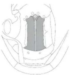
Loosen the 2 pins of the back pad. Attention, here you must additionally loosen the back pin of the cheek pad.
INSTALLATION INNER LINING
Installation the head pad
-
Connect the 4 pins of the head pad with the corresponding plug-in devices.
-
Connect the 2 pins of the side pad with the corresponding plug-in devices. Please note the markings of the right and left side pad.
natural_image
Technical line drawing of a mechanical component or housing (no text or symbols)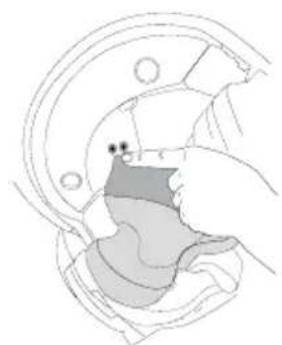
natural_image
Cross-sectional diagram of a mechanical component with no visible text or symbolsC. THE HELMET
-
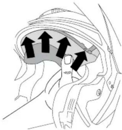
Fasten the forehead pad to the 4 holders and connect the pins with the corresponding plug-in devices.
-
Connect the 2 pins of the back pad with the plug-in devices. Press the open end over back pin of the cheek pad.
Installation the cheek pad
- Loosen the velcro.
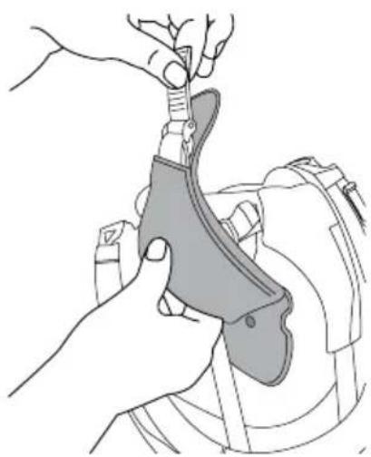
2.Slide the chin strap through the cheek pad pocket.
-
Close the Velcro fastener. Make sure that the tape is not twisted.
-
Connect the pins of the cheek pads with the corresponding plug-in devices.
-
Carefully place the cheek pad over the velcro strip of the side pad.
-
Repeat points 1 to 5 for the installation of the cheek pad on the other side.
natural_image
Diagram of a vehicle head and neck with directional arrows indicating movement or force (no text or symbols)EN
natural_image
Illustration of a hand using a tool to adjust or install a mechanical component (no text or symbols visible)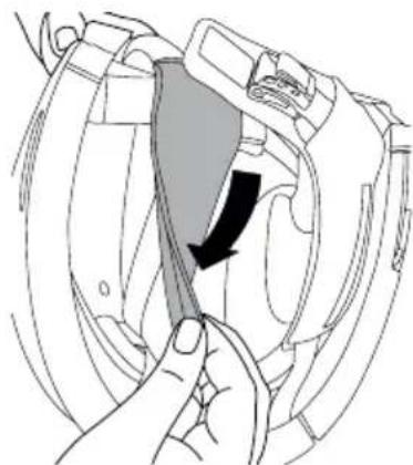
natural_image
Illustration of a hand holding a device with a black arrow indicating a process or operation (no text or symbols present)C. THE HELMET
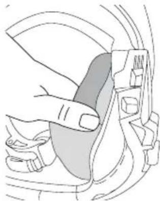
Installation the neckroll
- Insert the piping on one side.
- Position the piping all the way around in the closing edge.
- Insert the piping on the other side in.
- Pull the cheek pad a little inwards and and fasten the hooks on the right and left side.
natural_image
Illustration of a hand adjusting a car seatbelt mechanism (no text or symbols)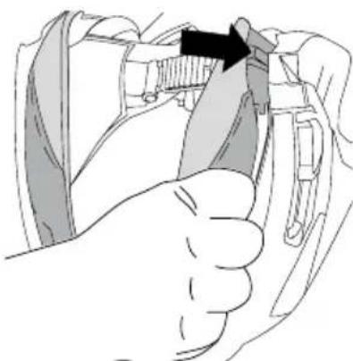
natural_image
Illustration of a hand inserting a cable into a device (no text or symbols visible)Note:
Ensure that the A.R.O.S. straps are not twisted.
Caution:
Never ride when parts of the inner lining have been removed.
Caution:
Excessive heat (e.g. exhaust heat) can cause damage to the inner lining!
Note:
To avoid damage to the inner lining and inner shell, do not hang the helmet over the mirrors or handlebar grips.
C. THE HELMET
13. VENTILATION SYSTEMS
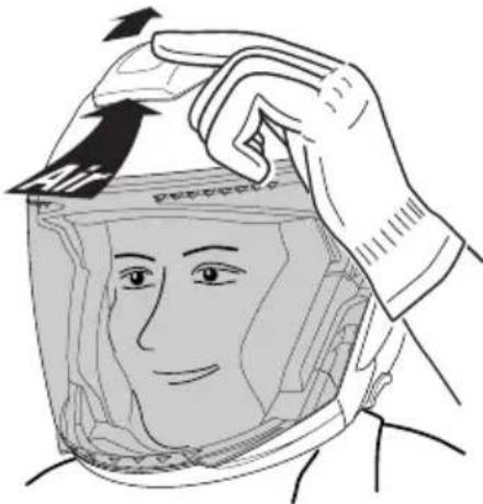
VENTILATION SYSTEM 1 - HEAD VENTILATION
There is a large air inlet cowl with a three-stage adjustable ventilation system on the top of the helmet shell for ventilating the top of your head. Air entering the helmet through this inlet cowl is directed via channels to the top of the head. Inside the helmet, the head padding system enables direct contact between incoming air and the surface of the head, thereby conducting the heat away from the inside of the helmet quickly. TPush the air inlet cowl back to the first latch position for partial ventilation. To open the inlet fully, push the air inlet cowl further back.
natural_image
Illustration of a person adjusting a helmet with an arrow indicating direction (no text or symbols)SUMMER AND WINTER ADJUSTMENT FLAPS
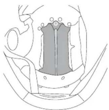
The ventilation of the J2 can also be adjusted to suit the seasons, weather conditions or your personal preferences. While you will prefer the cooling air current to flow directly on to your head in summer in autumn/winter you can reduce the volume of incoming cold air, or divert it, by covering the ventilation channels with the flaps of the head pad. To do so, raise the head pad and fold out the fabric flaps located behind the front section.
natural_image
Anatomical line drawing of a pelvic bone structure (no labels or text)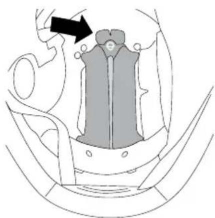
natural_image
Diagram of a mechanical component with an arrow indicating direction, no visible text or symbolsC. THE HELMET
VENTILATION DEVICE 2 - INTERIOR AIR EXTRACTION
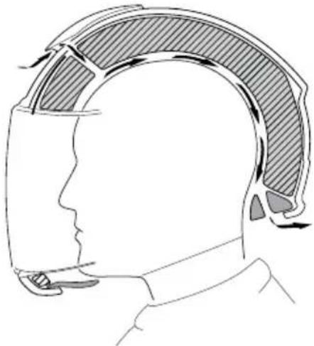
The J2 is equipped with an innovative air extraction system. Fresh air flowing in through the head vent is directed via the air channels in the inner shell to the back of the helmet. The reduced pressure that prevails at the back of the helmet ensures that the air is constantly sucked out through the air vents and special netting material fitted to the neck pad, thus guaranteeing a pleasant climate inside the helmet.
natural_image
Side profile illustration of a person wearing a helmet with shaded upper portion (no text or symbols)14. ADDITIONAL SAFETY FEATURES
REFLECTIVE PANELS
Black reflective patches on the neckroll and forehead area make the motorcyclist more visible. With solid-colour helmets (no decals) the SCHUBERTH logo on the back and the SCHUBERTH lettering in front of the helmet are also made of reflective foil.
Note:
Keep the reflective safety areas clean.
Note:
When riding in France, local law requires that further reflective safety stickers be attached to the front, back and both sides of the helmet.
Note:
Please note the information on the handling of the chin strap.
D. PUTTING THE HELMET ON AND TAKING IT OFF
1. PUTTING ON THE HELMET
- Make sure the sun visor is retracted into the helmet shell.
- Open the chinstrap and chinstrap comfort pad.
- Pull apart the lower ends of the chinstrap.
- It will now be easy to put the helmet on.
- Fasten the chinstrap and the chinstrap comfort pad.
- Make sure the chinstrap passes under the chin and fits snugly.
- Check that the chin guard is securely locked by pushing it upwards.
2. TAKING OFF THE HELMET
- Make sure the sun visor is retracted into the helmet shell.
2.Open the chinstrap. - Grasp the ends of the chinstrap and pull the chinstrap ends apart.
- The helmet can now be removed easily from the head.
Tip:
To avoid scratching any objects you might place the helmet on, we recommend closing the chin-strap after you have taken the helmet off.
For your safety, check the following points before every journey:
1. CHECKING THE HELMET
Check the helmet regularly for damage. Small superficial scratches will not impair the protective function of your helmet. In the case of more serious damage (cracks, dents, flaking and cracking paint, etc.), the helmet should no longer be used.
2. CHECKING THE CHINSTRAP
(WITH HELMET ON AND FASTENED)
- Check that the chinstrap passes under your chin.
- Slip your index finger under the chinstrap and pull.
If the chinstrap is loose under the chin, it is too long and needs to be tightened.
If the chinstrap loosens when you pull it, it is not properly fastened. Undo the chinstrap completely and try fastening it again. Repeat the test.
- If you are unable to fasten the chinstrap so that it fits snugly against the chin, check that your helmet is still the right size for you.
Note:
Repeat the test after each adjustment.
Caution:
Never ride with the chinstrap unfastened or incorrectly adjusted. The chinstrap should fit correctly and should not become loose when pulled. The fastener is not correctly closed if the chinstrap becomes loose when pulled.
3. CHECKING THE VISOR AND SUN VISOR
Before every journey, check that the mechanisms of the visor and sun visor are working properly and that the visor and sun visor will provide sufficiently clear visibility. Any dirt should be removed before riding.
Check the visor and sun visor for physical damage and cracks. A badly scratched visor will considerably impair your vision and should be replaced before setting off on a journey.
Caution:
Never use tinted visor or sun visor in conditions of poor visibility, when riding at night or in a tunnel.
Caution:
Stop riding if visibility is poor.
4. CHECKING THE CHIN BAR
Before every journey, check that the chin bar is properly fitted and that the chin bar is not presenting any physical damage and/or cracks.
A damaged mechanism and/or a damaged chin bar may compromise its functionality, potentially leading to detachment or breakage.
Caution:
Never ride with a not correctly fixed chin bar.
F. FOR YOUR SAFETY
1. SAFETY ADVICE CONCERNING THE HELMET
Motorcycling is associated with particular risks and dangers for the rider and passenger. Wearing a helmet can reduce but not eliminate the risk of serious injuries. It is impossible to state precisely what the protective effect of a helmet will be in the event of an accident. Safe riding techniques, adapted to the particular road and weather conditions, are essential for your safety.
To provide adequate protection, the helmet must fit well and be securely fastened.
Always fasten the chinstrap before setting off and check that the fastening system and strap are correctly in position.
Never ride with the chinstrap unfastened or incorrectly adjusted. The chinstrap must be correctly positioned and must not come loose when pulled. The fastener is not correctly closed if the chinstrap becomes loose when pulled.
The chin guard does not protect the chin from impacts.
The full protective function of a helmet can no longer be guaranteed after an accident or impact. Like the crumple zone of a car, the impact energy of a collision is absorbed by complete or partial destruction of the structure of the outer and/or inner shell of the helmet. Because of the way helmets are designed, this damage is rarely visible from the outside. The safety helmet is designed to absorb only one impact. It is therefore essential to replace the helmet after a fall, accident or other violent impact. For safety reasons, the old helmet should be rendered unusable.
The helmet safety mechanism described above can also cause small cracks in the shell when the helmet is dropped from a small height (less than 1 metre).
⚠️ Any helmet that has been subjected to a violent impact should be replaced.
No helmet provides absolute protection from all conceivable impacts. This helmet has been specially developed for motorcycle riding and is unsuitable for other purposes.
F. FOR YOUR SAFETY
Examine the helmet for damage at regular intervals. Small scratches will not impair the protective function of your helmet.
The helmet should be replaced after 5 to 7 years, depending on use and care. Although the outer shell is in principle capable of a longer service life, the occurrence of material fatigue and wear to other components, as well as the overall action of the helmet and the unknown conditions in which the helmet has been used, make it advisable for your own safety to replace the helmet after this period of use.
Excessive heat (e.g. exhaust heat) can cause damage to the decoration, the inner shell of the helmet and the interior lining.
Direct contact with motor fuel, thinners or solvents can destroy the structure of the inner and outer shell. Make sure the helmet does not come into contact with such substances, even for cleaning purposes.
Do not apply paint, stickers, petrol or other solvents to this helmet.
2. SAFETY ADVICE CONCERNING THE VISOR/SUN VISOR
The protective film used during shipping should be removed before use.
The anti-fog lens is supplied with a protective film. Remove this film before using the helmet for the first time.
Any scratches and/or dirt arising from the use of the visor and/or sun visors significantly impair your vision in any driving situation and thus increase the risk of an accident. For your own safety, replace them or clean them immediately.
Never use a tinted visor with marking "daytime use only" in conditions of poor visibility, at night or in a tunnel!
⚠ Benzine, solvent and fuel vapor can cause cracks in the visor. Keep the visor away from such vapors and do not allow these kinds of substances to come into direct contact with the visor! Never place the helmet on the tank of your motorcycle.
Make sure the visor is always in perfect condition. Don't ride when visibility is poor!
F. FOR YOUR SAFETY
3. SAFETY ADVICE CONCERNING MODIFICATIONS/ACCESSORIES
Original components (in particular on the outer shell, inner shell and restraint system) should not be altered or removed. The fitting of additional parts from other manufacturers that have not been recommended can reduce the protective effect and renders the ECE certification and all warranty and insurance claims invalid.
⚠ Use only original parts, replacement parts and accessories that SCHUBERTH has expressly approved for your helmet!
⚠️ Use of an unapproved accessoires will void the helmet approval.
G. MAINTENANCE AND CARE
1. HELMET SHELL
To clean the helmet shell, you can use water, soap or one of the commonly available motorcycle shampoos, cleaners, polishes, plastic cleaners or cleaning fluids. Using water and soap is usually sufficient. Make sure when using the other cleaning materials that these do not come into contact with the visor, since they can cause damage to the visor and its coating.
Note:
Never use motor fuel, thinners or solvents to clean the helmet. These substances can cause serious damage to the helmet with no external signs. The full safety function of the helmet can then no longer be guaranteed.
2. VISOR AND SUN VISOR
OUTER SURFACE OF THE VISOR
Use a soft cloth and a mild soap solution (< 20 °C) to remove dirt from the outside of the visor. To dry the visor, use a lint-free cloth and apply gentle pressure.
ANTI-FOG LENS
The Anti-fog lens must only be cleaned with a soft cloth, which may be slightly dampened if required (we recommend a mocrofibre cloth). Do not use any cleaning agents.
SUN VISOR
The sun visor should only be cleaned with a soft and, if necessary, slightly damp cloth (we recommend a microfibre cloth). Do not use any cleaning agents.
Note:
Only use tepid water (< 20 °C) for cleaning. Never on any account clean the visor or sun visor with petrol, solvent, a window or glass cleaner or other cleaning agents containing alcohol.
G. MAINTENANCE AND CARE
Note:
The visor should not be soaked in water even if it is very dirty on the outside, as this will severely reduce the surface hardness and thus the durability of the anti-fog/anti-scratch coating.
Note:
The visor should not be completely closed when not in use (particularly during periods of storage), as the moisture contained on the inside cannot escape if closed and will largely be absorbed by the anti-fog lens. This can lead to a reduction in the lifespan of the coating. Ideally, position the visor in the third locking setting above the city position.
Note:
Never attach labels, adhesive tape or stickers to the visor or sun visor.
Tip:
Stubborn soiling on the outside of the visor (e.g. dried-on insect residue) is easy to remove if you cover the closed visor with a damp cloth for a few minutes to soften the deposits. Repeat this procedure if required.
Note:
Always avoid temperatures above 40 °C and high humidity when choosing a place to store the visor, as these conditions can cause damage to the visor.
3. INNER LINING
The inner lining of the J2 can be removed completely. The neckroll, head and cheek pads can be washed by hand using a mild soap solution (e.g. with highly diluted standard mild detergent) at a maximum temperature of 30 °C . Allow the lining to dry at room temperature and with good ventilation.
4. VENTILATION
VENTILATION HOOD
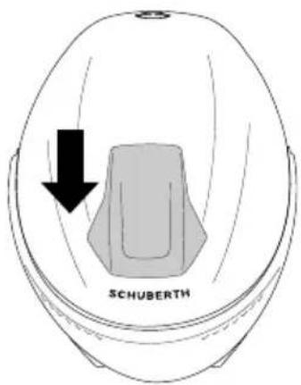
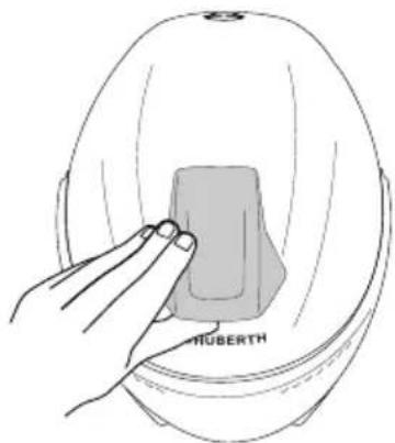
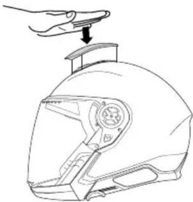
When necessary, the head ventilation system's air inlet hood can be removed to clean the ventilation mechanism and ventilation grille.
G. MAINTENANCE AND CARE
- Set the slider of the ventilation hood to the front.
text_image
SCHUBERTHEN
- Pull it upwards until the ventilation hood is released from the helmet shell.
text_image
HUBERTH- After cleaning, attach the ventilation hood by placing it on the bracket and pushing it downward under slight pressure until it clicks into place.
natural_image
Line drawing of a hand adjusting a helmet component with a handle (no text or symbols)- To ensure optimum ventilation, operate the ventilation slide.
G. MAINTENANCE AND CARE
5. RETENTION SYSTEM
The components of the retention system do not require maintenance.
6. STORING THE HELMET
Store the helmet in the helmet bag supplied in a dry, well-ventilated and stable place. Always position the helmet so that it cannot fall to the floor. Damage that occurs in this way is not covered by the warranty.
Note:
Store the helmet out of the reach of children and animals.
H. ACCESSORIES AND SPARE PARTS
1. COMMUNICATION SYSTEM
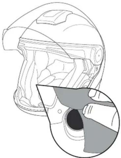
Your J2 comes with pre-installed HD speakers and 3 antennas for Bluetooth Intercom, Mesh Intercom and FM Radio, ready for the use of the SCHUBERTH communication systems powered by Sena and Cardo.
Find our more about our range of communication system at the following link:

text_image
QR code image containing encoded data and a central circular logo with textThe HD speakers are behind the cheek pads.
natural_image
Line drawing of a helmet with a magnified inset showing the interior detail (no text or symbols)You can find out more about the SC Systems from your specialist dealer and at WWW.SCHUBERTH.COM
H. ACCESSORIES AND SPARE PARTS
Caution:
The installation of a communication system (including basic headsets) constitutes a modification to the helmet. For this reason it is necessary for any communication system and headset intended for installation into a specific model of helmet to be tested and approved in line with the ECE-R 22.06 European helmet standard, otherwise the helmet's approval and compliance with insurance requirements become invalid on installation.
Evidence of approval in line with ECE-R 22.06 in connection with a specific communication system is only valid if certified by an official regulatory office of an EU member state. Any other form of information from these or other institutions (e.g. on the general suitability of communication systems for use in motorcycle helmets) is of no relevance and the helmet will lose its approval.
2. SCHUBERTH INDIVIDUAL PROGRAM
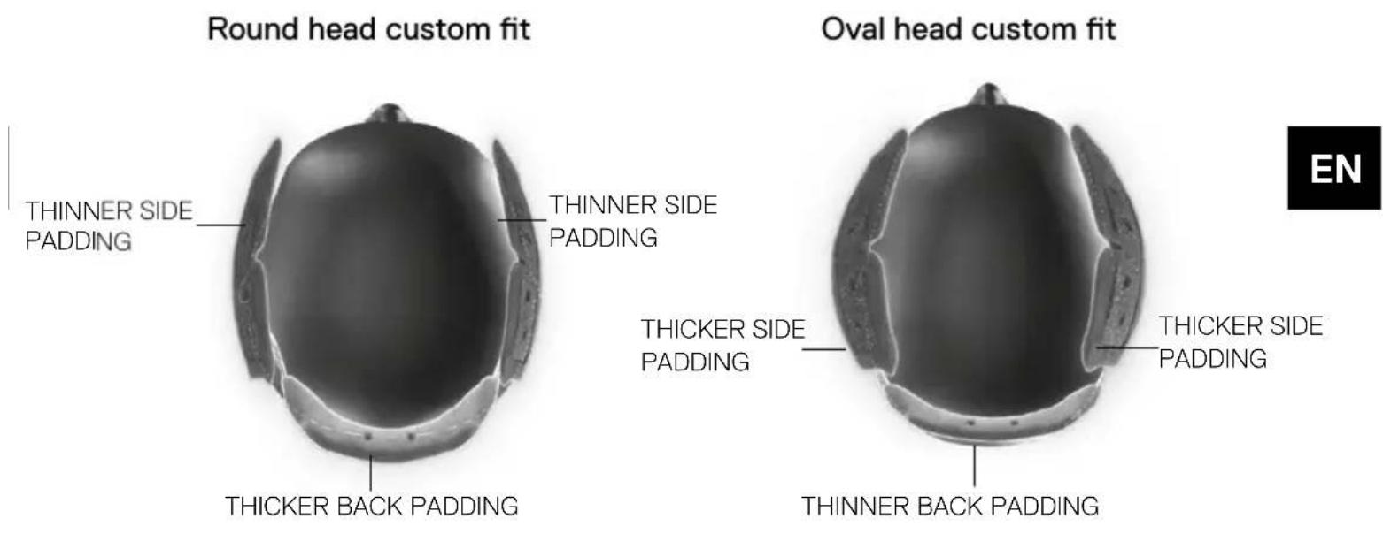
To develop the inner linings of the J2 SCHUBERTH used a scientific approach commissioningaStudytothe"HOHENSTEININSTITUTFORTEXTILINNOVATION". The result is an interior that optimally fits head shapes from round to oval, which make up more than 98% of the population. SCHUBERTH's claim is to offer everyone a perfect fit. That's why the SCHUBERTH individualization concept was introduced with the J2, allowing the fit to be customized.
In the case of an extremely oval head shape, you have the option of adjusting the head padding by installing thicker side pads and thinner back padding. In the case of an extremely round head shape you can use thinner side pads and a thicker back pad. This head pad customization is available for the sizes M to XL.
For all sizes, we also offer the option of optimizing the fit in the cheek area with two different cheek pads. The "Sport" cheek pads provide a more aggressive and stable fit and the "Comfort" cheek pads provide a softer and loose fit.
H. ACCESSORIES AND SPARE PARTS
text_image
Round head custom fit THINNER SIDE PADDING THINNER SIDE PADDING THICKER BACK PADDING Oval head custom fit THICKER SIDE PADDING THINNER BACK PADDING THICKER SIDE PADDING ENFor further information on the SCHUBERTH individual program, please visit our website WWW.SCHUBERTH.COM.
3. ACCESSORIES AND SPARE PARTS
An overview of all available accessories and spare parts can be found on the Internet at WWW.SCHUBERTH.COM
We recommend that you only use original SCHUBERTH accessories and spare parts for your SCHUBERTH helmet as they are specially adapted to your helmet model.
Caution:
For safety reasons, all other parts of the helmet should only be replaced by your specialist dealer.
4. ORDERING ORIGINAL SCHUBERTH PARTS
Please contact your specialist dealer for original SCHUBERTH accessories and replacements. To find your nearest SCHUBERTH specialist dealer, please go to WWW.SCHUBERTH.COM
I. SCHUBERTH SERVICE
Please contact your dealer if necessary, or you can call our service center directly. Find your local dealer as well as the contact details for our service center on the SCHUBERTH website at WWW.SCHUBERTH.COM
J. WARRANTY
Please check your statutory warranty entitlement in your country.
You can also enjoy the benefits of the “5 YEARS SCHUBERTH STANDARD GUARANTEE”. Register your J2 on the internet at WWW.SCHUBERTH.COM within 6 months from the purchase of the helmet to enjoy the privileges of your extended guarantee.
Should there be a problem with your product, please contact your dealer directly or through his service address, or you can call our service centre directly. If you return the product, please provide an accurate description of the fault. Please enclose a copy of your receipt if you have not yet registered for the "5 YEARS SCHUBERTH STANDARD GUARANTEE".
You can register your helmet following this QR-Code:

text_image
QR code image containing encoded data, with a central circular logo or watermark.
You will find the serial number on your ECE label (check the helmet Quick Start Guide leaflet to identify where it is located)
K. ENVIRONMENTAL PROTECTION
natural_image
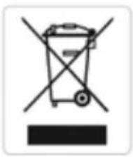
Symbol of a trash bin with no text or numbers, featuring crossed and unshaded lines (no text or labels)The symbol of the crossed-out trashcan indicates that this electrical or electronic equipment must not be disposed of with household waste at the end of its service life, but must be taken for separate collection. There are free collection points for waste electrical and electronic equipment in your area and, if necessary, other collection points for the reuse of the equipment. You can obtain the addresses from your city or local government. If the old electrical or electronic equipment contains personal data, you are responsible for deleting this data by yourself before returning it. If possible, please remove old batteries or rechargeable batteries from the old device before returning it for disposal. Please avoid the generation of waste from electrical or electronic equipment as much as possible, e.g. by giving preference to products with a longer service life or by reusing old electrical equipment instead of disposing.
L. HOW TO CONTACT US
HEADQUARTERS
Phone
+49 (0)391 8106-0
Address
SCHUBERTH GmbH
Stegelitzer Straße 12
39126 Magdeburg
Germany
Internet
WWW.SCHUBERTH.COM
info@schuberth.com
J2
MERCI BEAUCOUP POUR LA CONFIANCE,
natural_image
Technical line drawing of a helmet with labeled components (no text or symbols present)INSTALLER LA MENTONNIÈRE
natural_image
Technical line drawing of a helmet with internal components and directional arrows (no text or symbols)Note:
text_image
Illustration showing three-step instructions for handling a tool, labeled (1) and (2), with arrows indicating movement.Avertissement:
natural_image
Illustration of a person wearing a helmet with an arrow indicating direction (no text or symbols)C. LE CASQUE
FERMETURE DE LA VISIÈRE
natural_image
Illustration of a person in a helmet with hand gesture, no text or symbols presentFR
REEMPLACEMENT DE LA VISIÈRE
natural_image
Diagram of hands operating a mechanical device with a rotating arrow indicating rotation (no text or symbols present)natural_image
Illustration of a hand using a pliers to adjust a device, with an inset showing the close-up of the component (no text or symbols present)C. LE CASQUE
natural_image
Illustration of hands adjusting a helmet component with arrows indicating direction (no text or symbols)natural_image
Illustration of a person's helmet with arrows indicating clockwise motion (no text or symbols)LENTILLE ANTI-BUÉE (EN OPTION)
Démontage
natural_image
Illustration of two hands holding a shaded bandage, with numbered labels 1, 2, and 3 indicating positions (no text or symbols present)FR
natural_image
Illustration of a hand holding a small object with a magnified inset showing a face (no text or symbols present)Montage
natural_image
Illustration of a hand holding a small object with an arrow pointing to it, and a magnified inset showing a finger insertion (no text or symbols)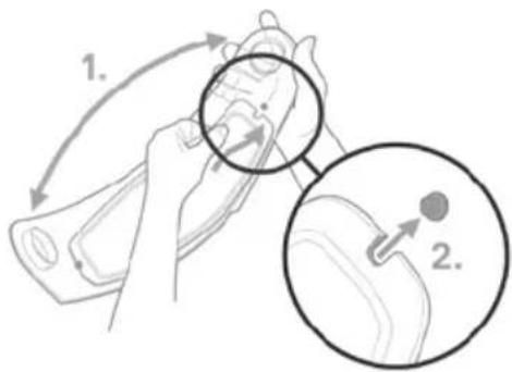
text_image
1. 2.C. LE CASQUE
natural_image
Diagram showing a hand holding a small object with an inset close-up of a mechanical component (no text or symbols)flowchart
graph TD
    A["Step 1: Dog-shaped bowl"] --> B["Step 2: Potato with rotation arrow"]
    B --> C["Step 3: Potato with rotation arrow"]
Attention:
natural_image
Technical line drawing of a helmet with directional arrows indicating motion or movement (no text or symbols)natural_image
Line drawing of a motor helmet showing the front and side views, with an inset close-up highlighting the steering wheel (no text or symbols present)Attention:
natural_image
Line drawing of a hand using a tool to adjust or install a vehicle component (no text or symbols visible)C. LE CASQUE
natural_image
Line drawing of a car's side panel showing hand placement and valve mechanism (no text or symbols)natural_image
Line drawing of a person's seatbelt with arrows indicating movement or force (no text or symbols)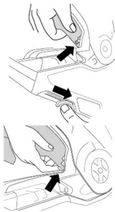
natural_image
Diagram showing two steps of a hand turning a car's seatbelt, with arrows indicating the process (no text or symbols present)C. LE CASQUE
12. L'INTÉRIEUR
natural_image
Line drawing of a hand holding a car seatbelt, showing mechanical components without any text or symbolsC. LE CASQUE
natural_image
Line drawing of a hand gripping a helmet (no text or symbols)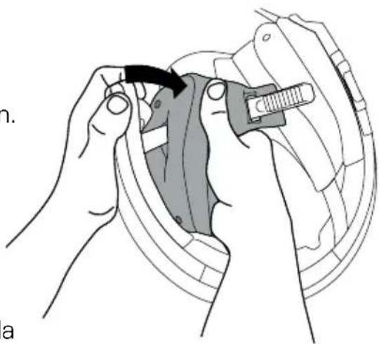
natural_image
Illustration of hands using a mechanical tool to adjust or install a component, no text or symbols present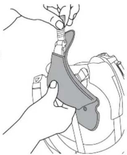
natural_image
Illustration of hands using a tool to adjust or install a mechanical component (no text or symbols visible)C. LE CASQUE
DÉMONTAGE DE LA COIFFE
natural_image
Illustration of a hand pressing down on a curved object with arrows indicating force or movement (no text or symbols present)FR
natural_image
Line drawing of a hand holding a small object, possibly a plant or container, with no visible text or symbols.natural_image
Illustration of a hand holding a car wheel, showing the wheel and seat area (no text or symbols)MONTAGE DE LA COIFFE
natural_image
Diagram of a pelvic region with no visible text or symbols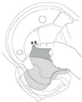
natural_image
Diagram of a hand holding a small object within a mechanical component (no text or symbols visible)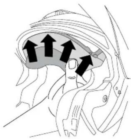
natural_image
Anatomical diagram of a human head and neck region with directional arrows indicating movement or force (no text or labels present)C. LE CASQUE
MONTAGE DES MOUSSES DE JOUE
natural_image
Illustration of a hand using a tool to adjust or install a mechanical component (no text or symbols visible)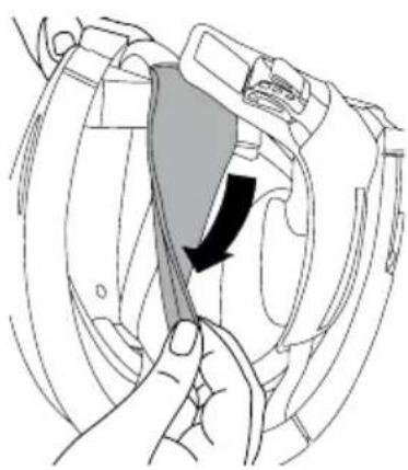
natural_image
Illustration of a hand holding a device with a black arrow indicating direction (no text or symbols)
natural_image
Illustration of a hand pressing down on a mechanical component (no text or symbols visible)C. LE CASQUE
natural_image
Illustration of a hand inserting a cable into a car seatbelt (no text or symbols)Avertissement:
natural_image
Illustration of a person adjusting a helmet with arrows indicating motion (no text or symbols)VOLETS D'AJUSTEMENT ÉTÉ ET HIVER
natural_image
Anatomical line drawing of a pelvic region with no visible text or labels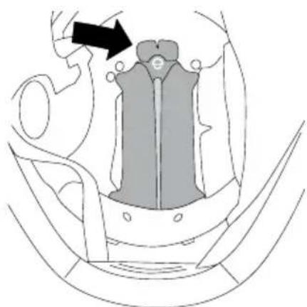
natural_image
Anatomical diagram of a pelvic region with an arrow indicating a specific area (no text or labels present)C. LE CASQUE
VENTILATION 6 - EXTRACTEUR D'AIR
natural_image
Side profile illustration of a helmet with shaded anatomical structure (no text or symbols)14. EQUIPEMENT DE SÉCURITÉ SUPPLÉMENTAIRE
text_image
QR code image with a central circular logo, likely linking to a digital resource or website.natural_image
Line drawing of a helmet with an inset close-up showing a hand holding a camera lens (no text or symbols)text_image
QR code image with a central circular logo, likely linking to a digital resource or website.Conseil :
natural_image
Symbol of a trash bin with no text or labelstext_image
Diagram illustrating hand positioning and movement of a device with labeled parts 1 and 2Consiglio:
natural_image
Technical illustration of a mechanical component with a magnified inset showing a close-up detail (no text or symbols)Note:
natural_image
Technical line drawing of a helmet with labeled components (no text or symbols present)natural_image
Technical line drawing of a helmet with internal components and directional arrows indicating movement (no text or symbols)Note:
text_image
Illustration showing three-step instructions for handling a tool, labeled (1) and (2), with arrows indicating movement.Consiglio:
natural_image
Illustration of a person wearing a full-body helmet with an arrow indicating direction (no text or symbols)C. IL CASCO
natural_image
Illustration of a person in a helmet with hand gesture, showing head and torso positioning (no text or symbols)IT
SOSTITUZIONE DELLA VISIERA
natural_image
Illustration of hands holding a device with a rotating arrow indicating rotation (no text or symbols)natural_image
Diagram showing hands operating a device with an inset close-up of the component (no text or symbols visible)C. IL CASCO
natural_image
Illustration of hands holding a helmet with a visible internal structure (no text or symbols)natural_image
Illustration of a person's helmet with arrows indicating motion or force direction (no text or symbols)natural_image
Illustration of hands performing a bandage exercise with labeled clips (no text or symbols present)C. IL CASCO
natural_image
Illustration of hands using a tool to adjust or install a face mask, with a magnified inset showing the mask detail (no text or symbols present)IT
Montaggio
natural_image
Illustration of a hand holding a banana with a magnified inset showing the process (no text or symbols)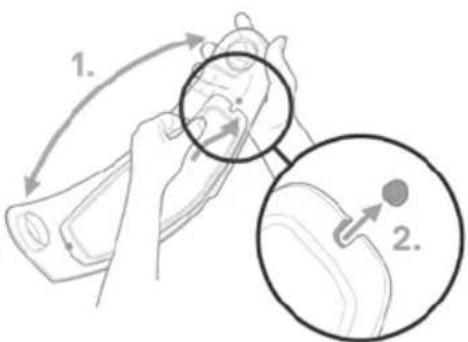
text_image
1. 2.C. IL CASCO
natural_image
Illustration of a hand holding a small object, with an inset showing a magnified view of a mechanical component (no text or symbols present)flowchart
graph TD
    A["Red Squirrel Head"] --> B["Mouse 1: Left side"]
    B --> C["Mouse 2: Right side with mouse head"]
    C --> D["Mouse 3: Right side with mouse legs"]
Attenzione:
natural_image
Technical line drawing of a helmet with directional arrows indicating movement (no text or symbols)natural_image
Technical line drawing of a helmet component with an inset showing a close-up of the handle (no text or symbols)Attenzione:
natural_image
Line drawing of a hand using a tool to adjust or install a vehicle component (no text or symbols visible)natural_image
Line drawing of a car's steering wheel and grip mechanism (no text or symbols)C. IL CASCO
Installazoine visierino solare
natural_image
Line drawing of a person's seatbelt with arrows indicating movement or force (no text or symbols)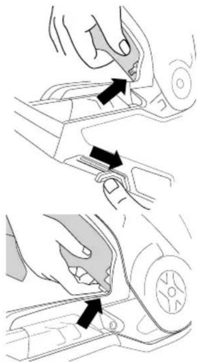
natural_image
Illustration of a hand using a tool to adjust or install a car interior panel (no text or symbols present)12. IMBOTTITURA
natural_image
Line drawing of a hand pressing down on a car seatbelt (no text or symbols)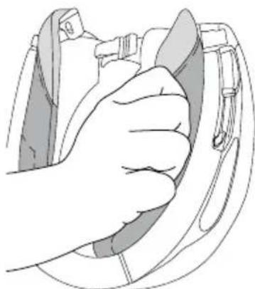
natural_image
Illustration of a hand holding a helmet buckle (no text or symbols)C. IL CASCO
natural_image
Illustration of a hand holding a medical device to adjust a patient's chest (no text or symbols present)natural_image
Anatomical illustration of a human brain with black arrows indicating specific regions (no text or labels present)C. IL CASCO
natural_image
Illustration of a hand holding a leaf, with no visible text or symbolsnatural_image
Medical illustration showing a hand holding a device within a circular anatomical structure (no text or labels)natural_image
Diagram of a mechanical component with no visible text or symbolsnatural_image
Diagram of a mechanical component with a highlighted section (no text or symbols)C. IL CASCO
natural_image
Diagram of a vehicle's seatbelt with directional arrows indicating movement or force (no text or symbols)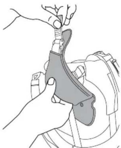
natural_image
Illustration of hands using a tool to adjust or install a mechanical component (no text or symbols visible)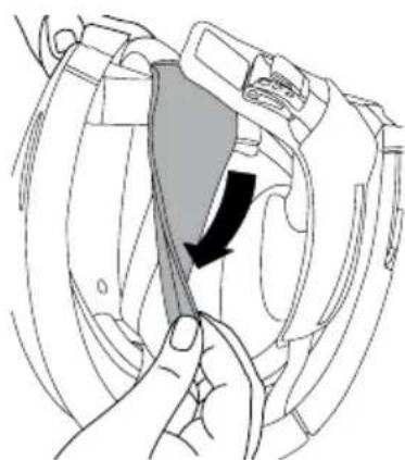
natural_image
Illustration of a hand holding a device with a black arrow indicating a directional change (no text or symbols present)C. IL CASCO
natural_image
Illustration of a hand adjusting a car seatbelt (no text or symbols visible)