
ND6225 - Hydraulic tool Vevor - Free user manual and instructions
Find the device manual for free ND6225 Vevor in PDF.

| Product Type | Hydraulic Tire Bead Breaker (Bead breaking disc) |
| Brand | Vevor |
| Model | ND6225 |
| Maximum Pressure | 10,000 psi (689 bar) |
| Operating Range (Stroke) | 127 mm (5 inches) |
| Color | Yellow |
| Power Source | External pneumatic/hydraulic pump (compressed air: 5-10 CFM at 100 psi) |
| Compatible Wheel Types | All types except 5-piece earthmover rims |
| Applications | Truck tires, agricultural tractor, grader, combine harvester, skidder |
| Main Material | Heavy-duty steel |
| Weight | Approx. 15 kg (estimated) |
| Dimensions (L x W x H) | Approx. 60 x 30 x 20 cm (estimated) |
| Functions | Breaks tire bead for disassembly |
| Safety | Wear PPE (helmet, goggles, gloves, safety shoes); keep hands away from jaw |
| Maintenance | Check air levels, clean relief valve, inspect springs and check balls |
| Spare Parts | Available (see parts list in manual) |
| Repairability | User-repairable (seals, balls, springs) |
| Warranty | Electronic warranty certificate via www.vevor.com/support |
| User Manual | Available in PDF on notice-facile.com |
Frequently Asked Questions - ND6225 Vevor
User questions about ND6225 Vevor
0 question about this device. Answer the ones you know or ask your own.
Ask a new question about this device
Download the instructions for your Hydraulic tool in PDF format for free! Find your manual ND6225 - Vevor and take your electronic device back in hand. On this page are published all the documents necessary for the use of your device. ND6225 by Vevor.
USER MANUAL ND6225 Vevor
Technical Support and E-Warranty Certificate www.vevor.com/support
HYDRAULIC BEAD BREAKER
MODEL: ND6225
We continue to be committed to provide you tools with competitive price. "Save Half", "Half Price" or any other similar expressions used by us only represent of savings you might benefit from buying certain tools with us compared top brands and does not necessarily mean to cover all categories of tools offered are kindly reminded to verify carefully when you are placing an order with us actually saving half in comparison with the top major brands.
VEVOR®
TOUGH TOOLS, HALF PRICE
HYDRAULIC BEAD BREAKER
MODEL: ND6225
natural_image
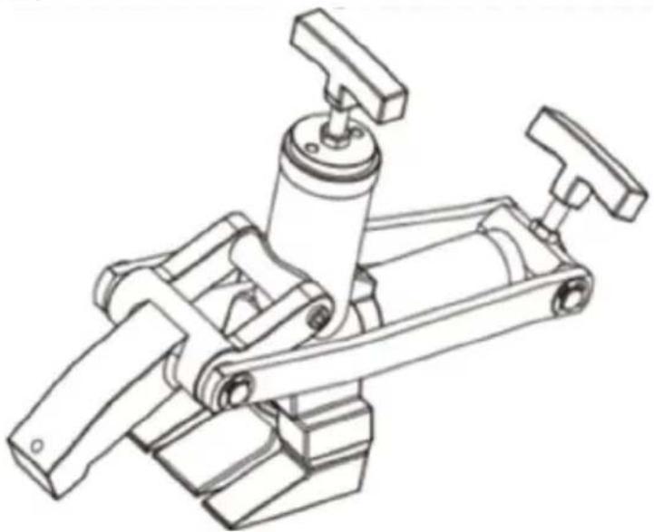
Technical line drawing of a mechanical clamp or lever assembly (no text or symbols)| Spare Parts | 36.7 × 3.5 Oring × 2 | 47.5 × 3 Oring × 1 | 45 × 38 × 5 Yring × 2 |
NEED HELP? CONTACT US!
Have product questions? Need technical support? Please feel fr contact us:
Technical Support and E-Warranty Certificate www.vevor.com/support
This is the original instruction, please read all manual instruction carefully before operating. VEVOR reserves a clear interpretation user manual. The appearance of the product shall be subject to product you received. Please forgive us that we won't inform your data on our product.
SAFETY INFORMATION
To avoid personal injury or property damage while using this product, read a follow all DANGERS, WARNINGS, CAUTIONS, and INSTRUCTIONS that are attached to, or included with, this product.
- Follow the instructions of the tire manufacturer and the vehicle manufacture when deflating, demounting, mounting, and inflating tires.
- These operating instructions do not apply to any specific rim. Therefore, the rim manufacturer for the correct procedure for your rim.
WARNING
To avoid serious personal injury, always wear proper protective gear, such as hats, safety glasses, gloves, and steel toe shoes when using hydraulic equipn
DESCRIPTION
The Bead Breaker is used on all types of rims except 5-piece earth mover activated by air hydraulic pumps with maximum0,000psi output pressure. It is ideal for use with truck, farm tractor, grader, combine. And skidder tires.
PRODUCT PAREMETERS
| Model | ND6225 |
| Maximum Pressure | 10000psi |
| Operating Range | 5inch / 127mm |
| Colour | Yellow |
OPERATION
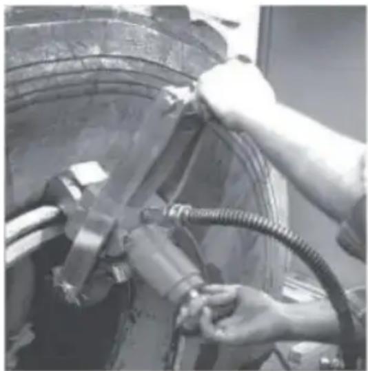
The optional air/hydraulic pump is capable of generating fluid pressure up to 10,000 psi. Keep both hands on the handles and away from the clamping breaker tongue. Make certain that the tool is properly aligned on the rim bef allowing the bead breaking action. Do not continue to operate the air/Hydraulic pump once the breaker rod is completely extended. Failure to comply with the instructions could result in personal injury or damage to the equipment.
natural_image
Close-up of hands adjusting a car tire and hoses, no visible text or symbols- Make certain the tire is completely deflated.
- Connect the hose of an air/hydraulic Pump to the hydraulic coupling on the Bead Breaker tool. Connect the air Supply line to the air/hydraulic pump.
- Air supply should be 5-10 CFM at 100 psi to obtain proper operating characteristics. In addition, the air line Should be equipped with an airline filter.
- Position the Bead Breaker so that the cup point set screw in the jaw ma solid contact with the rim and the teeth are positioned in the crevice between bead of the tire and the rim.
- When a tire has a trash guard, you may have to drive two straight tire between the rim and the Tire bead to get a starting point for the teeth. Ste PUMP end of the pump pedal. The clamping rod will begin to extend and the will grip the rim.
Caution
Make Certain that the teeth are slipping in between the rim and the bead. I depress the RELEASE end of the pump pedal and realign the tool. If the to positioned correctly, extending the breaker rod may damage the tool. Continue pumping until the tongue of the Bead Breaker pushes the bead free of the Depress the RELEASE end of the pump pedal
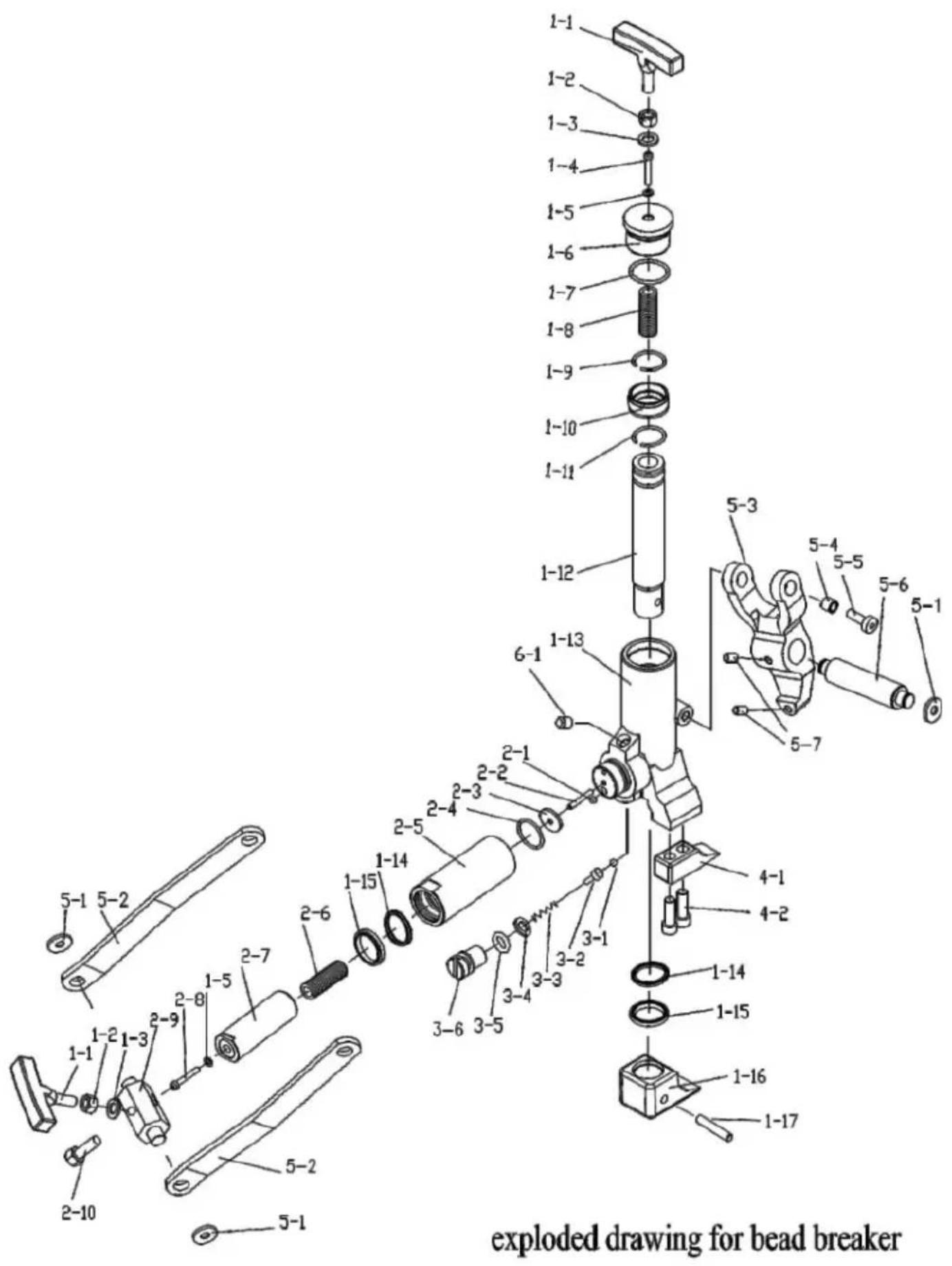
PARTS LIST
| ITEM | DESCRIPTION | ITEM | DESCRIPTION | |
| 1-1 | handle | 2-6 | spring | |
| 1-2 | M12 nut | 2-7 | piston rod | |
| 1-3 | Φ12 washer | 2-8 | M5x 70 screw | |
| 1-4 | M5 x 50 screw | 2-9 | joint block | |
| 1-5 | Φ5 copper washer | 2-10 | M12x 45 bolt | |
| 1-6 | cylinder cap | 3-1 | Φ8 steel ball | |
| 1-7 | o ring | 3-2 | ball seat | |
| 1-8 | spring A | 3-3 | spring | |
| 1-9 | snap ring | 3-4 | Φ12copper washer | |
| 1-10 | bushing | 3-5 | copper washer | |
| 1-11 | snap ring | 3-6 | M12 x20 screw | |
| 1-12 | piston rod | 4-1 | Left foot | |
| 1-13 | cylinder body | 4-2 | M10x15 screw | |
| 1-14 | Y-seal | 5-1 | snap ring | |
| 1-15 | bushing | 5-2 | Connection rod | |
| 1-16 | Extrusion leg | 5-3 | claw | |
| 1-17 | pin | 5-4 | bushing | |
| 2-1 | Φ6 steel ball | 5-5 | M10x25 screw | |
| 2-2 | M6 x 30 screw | 5-6 | shaft | |
| 2-3 | washer | 5-7 | screw | |
| 2-4 | o ring | 6-1 | plug | |
| 2-5 | cylinder |
TROUBLESHOOTING
| SVMPTOM | PROBABLE CAUSE |
| RODS EXTEND TOO SLOWLY | Insufficient hydraulic pressure form pump1.Check air supply(5-10CFM@100PSI)2.Check clearance of inlet check ball, ball must be fl or below end of filter adapter. |
| RODS FAIL TO RETRACT | Hydraulic pump does not release1.Dirt under pedal in release valve area-clean pedal.Bearing is misaligned on breaker rod-Correct or replace Broken or weak springs-Replace. |
| BOTH RODS EXTEND ATTHE SAME TIME | Hydraulic pressure in breaker cylinder increases before clamping rod is fully extended.1.Sequence ball not seated or broken or weak spring-correct or replace.2.Loose screw and ball not seated-correct or replace |
| BREAKER ROD RETRACTSAFTER CLAMPING ROD | Hydraulic pressure in breaker cylinder is not being re1.Fluid return ball did not reseat-correct or replace.2.Dirt plugging return port clean. Weak or broken spr breaker cylinder-Replace |
| PUMP DOES NOT RECIPROCATE | Air piston stuck.1.Check cylinder bore of pump for contamination or lubrication.2.Piston poppet not sealing-Replace |
| PUMP RECIPROCATES RAW WILL NOT EXTEND | Check prime.1.Depress both air valve and hydraulic release valve same time. |
| PUMP EXTENDS RAM BUT WILL NOT HOLD SYSTEM PRESSURE | 1.Outlet check ball not sealing properly-Correct or Rep2.Release valve mechanism not sealing properly. Check pin, ball. Release poppet and poppet retainer-Correct Replace. |
| PUMP EXTENDS RAM BUT WILL NOT BUILTO MAXIMUM PRESSURE. NO VISIBLE SIGNS OLEAKAGE | 1.Check air supply(5-10CFM@100psl)2.Check for internal leakage.A. Release valve mechanism.B. Low relief valve setting.C. Inlet check ball not seating properly-Correct or Re |
| PUMP EXTENDS RAM BUT WILL NOT BUILD MAXIMUM PRESSURE.VISIBLE SIGN OF LEAKAGE THROUGH AIR EXHAUST MUFFLER | 1.Check piston sub-assemblyA. Replace copper gasket and assemble in vertical pB. Replace position packing. |
VEVOR®
TOUGH TOOLS, HALF PRICE
Technical Support and E-Warranty Certificate
www.vevor.com/support
VEVOR®
TOUGH TOOLS, HALF PRICE
natural_image
Technical line drawing of a mechanical clamp or clamping device (no text or symbols)| De rechange | 36,7 × 3,5 O | 47,5 × 3 O 45 × 38 × 5 | Y |
| Parties | anneau × 2 anneau × 2 | anneau × 1 |
BESOIN D'AIDE? CONTACTEZ-NOUS!
PARAMÈTRES DU PRODUIT
natural_image
Close-up of hands adjusting a mechanical component with hoses and tubing (no visible text or symbols)DÉPANNAGE
natural_image
Technical line drawing of a mechanical clamp or clamping device (no text or symbols)natural_image
Close-up of hands adjusting a mechanical component with hoses and tubing (no visible text or symbols)FEHLERBEHEBUNG
www.vevor.com/support
VEVOR®
TOUGH TOOLS, HALF PRICE
natural_image
Technical line drawing of a mechanical clamp or clamping device (no text or symbols)| RicambioParti | ÿ36.7x3.5 Oanello ×2 | ÿ47.5x3 Oÿ45xÿ38anello ×1 | x5 Yanello ×2 |
natural_image
Close-up of hands adjusting a mechanical component with hoses and tubing (no visible text or symbols)elettronica www.vevor.com/support
VEVOR®
TOUGH TOOLS, HALF PRICE
natural_image
Technical line drawing of a mechanical clamp or clamping device (no text or symbols)| Repuesto | 36,7 × 3,5 O | 47,5 × 3 O 45 × | 38x5 Y |
| Regiones | anillo × 2 | anillo × 1 | anillo × 2 |
natural_image
Close-up of hands adjusting a mechanical component with hoses and tubing (no visible text or symbols)natural_image
Technical line drawing of a mechanical clamp or clamping device (no text or symbols)natural_image
Close-up of hands adjusting a mechanical component with hoses and tubing (no visible text or symbols)ROZWIAZYWANIE PROBLEMÓW
natural_image
Technical line drawing of a mechanical clamp or clamping device (no text or symbols)| SparenOnderdelen | ÿ36.7x3.50ringen ×2 ringen ×2 | ÿ47.5x30 y45xÿ38x5ringen ×1 | J |
HULP NODIG? NEEM CONTACT MET ONS OP!
natural_image
Close-up of hands adjusting a mechanical component with hoses and tubing (no visible text or symbols)PROBLEEMOPLOSSING
garantiecertificaat www.vevor.com/support
VEVOR®
TOUGH TOOLS, HALF PRICE
natural_image
Technical line drawing of a mechanical clamp or clamping device (no text or symbols)| SkonaDelar | ÿ36,7x3,5 Oring × 2 | ring ×1 | ÿ45xÿ38x5 Yÿ47,5x3 Oring × 2 |
BEHÖVER HJÄLP? KONTAKTA OSS!
natural_image
Close-up of hands adjusting a mechanical component with hoses and tubing (no visible text or symbols)FELSÖKNING
www.vevor.com/support


