
28104-3 - Carpentry template Vevor - Free user manual and instructions
Find the device manual for free 28104-3 Vevor in PDF.
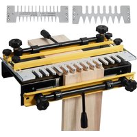


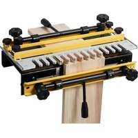
| Product Type | Luxury Dovetail Jig |
| Brand | Vevor |
| Model | 28104-3 |
| Usage | Assembly of through, half-blind, sliding dovetails and box joints |
| Base Material | Heavy-duty Steel |
| Template Material | Machined Aluminum |
| Wood Thickness Capacity | 1/4" to 1-1/8" (6.35 mm to 28.6 mm) |
| Maximum Joint Length | 12" (305 mm) |
| Clamps | 2 cam clamps with adjustment knobs and quick-release levers |
| Included Accessories | 1/2" and 1" through templates, 1/2" half-blind template, dovetail bits and straight bits, shaft adapters, positioning discs, hex keys, handles |
| Required Collet Diameter | 1/2" (12.7 mm) for the router |
| Number of Templates Supplied | 3 (1/2" through, 1" through, 1/2" half-blind) |
| Weight (approx.) | Approximately 4.5 kg |
| Base Dimensions (approx.) | 360 x 200 mm |
| Power | None (manual tool requiring an electric router not included) |
| Safety | Use ANSI Z87.1 safety glasses, hearing protection, and follow the manual instructions |
| Maintenance | Clean parts after use, lubricate moving parts, store in a dry place |
| Spare Parts | Replacement parts available through Vevor customer service |
| Warranty | Electronic warranty certificate available at www.vevor.com/support |
| Origin | Made in China, imported by Sanven Technology Ltd. (USA) |
Frequently Asked Questions - 28104-3 Vevor
User questions about 28104-3 Vevor
0 question about this device. Answer the ones you know or ask your own.
Ask a new question about this device
Download the instructions for your Carpentry template in PDF format for free! Find your manual 28104-3 - Vevor and take your electronic device back in hand. On this page are published all the documents necessary for the use of your device. 28104-3 by Vevor.
USER MANUAL 28104-3 Vevor
Technical Support and E-Warranty Certificate www.vevor.com/support
Dovetail Jig
MODEL: 28104-1 28104-3
We continue to be committed to providing you with tools at competitive prices. "Save Half", "Half Price", or any other similar expressions used by us only represent an estimate of savings you might benefit from buying certain tools with us compared to the major top brands and do not necessarily mean to cover all categories of tools offered by us. You are kindly reminded to verify carefully when placing an order with us if you are actually saving half in comparison with the top major brands.
Please view the installation video of the product.

VEVOR®
TOUGH TOOLS, HALF PRICE
Dovetail Jig
MODEL: 28104-1 28104-3
NEED HELP? CONTACT US!
Have product questions? Need technical support? Please feel free to contact us:
Technical Support and E-Warranty Certificate www.vevor.com/support
This is the original instruction. Please read all manual instructions carefully before operating. VEVOR reserves a clear interpretation of our user manual. The appearance of the product shall be set to the product you received. Please forgive us that we won't in again if there are any technology or software updates on our
SAFETY GUIDELINES - DEFINITIONS
This manual contains information that is important for you to know and understand. This information relates to protecting YOUR SAFETY and PREVENTING EQUIPMENT PROBLEMS. To help you recognize this information, we use the symbols to the left. Please read the manual and pay attention to these sections.
DANGER
avoided, will
Indicates an imminently hazardous situation which, if not avoided, will result in death or serious injury.
WARNING
avoided, could
Indicates a potentially hazardous situation which, if not avoided, could result in death or serious injury.
CAUTION
avoided, may
Indicates a potentially hazardous situation which, if not avoided, may result in minor or moderate injury.
CAUTION
Used without the safety alert symbol indicates a potentially hazardous situation which, if not avoided, may result in property damage.
IMPORTANT SAFETY INSTRUCTIONS
WARNING
Read and understand all instructions. Failure to follow all instructions listed below may result in electric shock, fire and/or serious personal injury.

SAVE THESE INSTRUCTIONS.
WARNING
There are certain applications for which this tool was
designed. VEVOR strongly recommends that this tool NOT be modified and/or used for any application other than for which it was designed. If you have any questions relative to its application, DO NOT use the tool until you have written VEVOR and we have advised you.
- KEEP WORK AREA CLEAN. Cluttered areas and benches invite injuries.
- AVOID DANGEROUS ENVIRONMENT. Don't expose power tools to rain. Don't use power tools in damp or wet locations. Keep area well lit. Avoid chemical or corrosive environment. Do not use tool in presence of flammable liquids or gases.
- GUARD AGAINST ELECTRIC SHOCK. Prevent body contact with grounded surfaces. For example: pipes, radiators, ranges, refrigerator enclosures.
- KEEP CHILDREN AWAY. Do not let visitors contact tool or extension cord. All visitors should be kept away from work area.
- STORE IDLE TOOLS. When not in use, tools should be stored in a secure, dry place – out of reach of children.
- DON'T FORCE TOOL. It will do the job better and safer at the rate for which it was intended.
- USE RIGHT TOOL. Don't force small tool or attachment to do the job of a heavy duty tool. Don't use tool for purpose not intended – for example – do not use a circular saw for cutting tree limbs or logs.
- DRESS PROPERLY. Do not wear loose clothing or jewelry. Loose clothing, draw strings, and jewelry can be caught in moving parts. Rubber gloves and non-skid footwear are recommended when working outdoors. Wear protective hair covering to contain long hair.
- USE ANSI Z87.1 SAFETY GLASSES. Wear safety glasses or goggles while operating power tools. Also wear a face or dust mask if the operation creates dust. All persons in the area where power tools are being operated should also wear safety glasses and a face or dust mask.
- DON'T ABUSE CORD. Never carry the tool by the cord or yank it to disconnect from the receptacle. Keep the cord away from heat, oil, and sharp edges. Have damaged or worn power cords and strain relievers replaced immediately. DO NOT ATTEMPT TO REPAIR THE POWER CORD.
- SECURE WORK. Use clamps or a vise to hold the work. It's safer than using your hands and it frees both hands to operate the tool.
- DON'T OVERREACH. Keep proper footing and balance at all times.
- MAINTAIN TOOLS WITH CARE. Keep tools sharp and clean for better and safer performance. Follow instructions for lubricating and changing accessories. Inspect tool cords periodically and, if damaged, have them repaired by an authorized service facility. Inspect extension cords periodically and replace if damaged. Have all worn, broken, or lost parts replaced immediately. Keep handles dry, clean, and free from oil and grease.
- DISCONNECT TOOLS when not in use, before servicing, and when changing accessories such as blades, bits, cutters, etc.
- REMOVE ADJUSTING KEYS AND WRENCHES. Form the habit of checking to see that keys and adjusting wrenches are removed from the tool before turning it on.
- AVOID UNINTENTIONAL STARTING. Do not carry a plugged-in tool with your finger on the switch. Be sure the switch is off when plugging in. Keep hands, body, and clothing clear of blades, bits, cutters, etc. when plugging in the tool.
- OUTDOOR USE EXTENSION CORDS. When the tool is used outdoors, use only extension cords marked "Suitable for use with outdoor appliances – store indoors when not in use." If an extension cord is to be used outdoors, it must be marked with the suffix W-A or W following the cord type designation.
- STAY ALERT. Watch what you are doing. Use common sense. Do not operate the tool when you are tired or while under the influence of medication, alcohol, or drugs.
- CHECK DAMAGED PARTS. Before further use of the tool, a guard or other part that is damaged should be carefully checked to determine that it will operate properly and perform its intended function. Check for alignment of moving parts, binding of moving parts, breakage of parts, mounting, and any other conditions that may affect its operation. A guard or other part that is damaged should be properly repaired or replaced by an authorized service center unless otherwise indicated elsewhere in this instruction manual. Have defective switches replaced by authorized service center. Do not use tool if switch does not turn it on and off.
- WEAR ANSI S3.19 EAR PROTECTION to safeguard against possible hearing loss.
ADDITIONAL SAFETY RULES
WARNING
FAILURE TO FOLLOW THESE RULES MAY RESULT IN SERIOUS PERSONAL INJURY.
- READ AND FOLLOW ALL SAFETY INSTRUCTIONS in the instruction manual supplied with your router.
- SECURE WORK. Be sure Dovetail Fixture/Jig and work is anchored securely to prevent movement.
- BE SURE CORD SET IS FREE and will not hang up during routing operations.
- KEEP HANDS CLEAR of cutter when motor is running to prevent personal injury.
- MAINTAIN FIRM GRIP on router when starting motor to resist starting torque.
- STAY ALERT and keep cutter free, clear of all foreign objects while motor is running.
- BE SURE MOTOR HAS COMPLETELY STOPPED before
Removing router from Dovetail Fixture/Jig and setting Dovetail Fixture/Jig down between operations.
- NEVER REMOVE ROUTER MOTOR from router base while
template guide and dovetail bit are installed. The dovetail bit may not fit through the hole in the template guide.
- TIGHTEN TEMPLATE GUIDE LOCKNUT SECURELY.
- SOME WOOD CONTAINS PRESERVATIVES WHICH CAN BE
TOXIC. Take extra care to prevent inhalation and skin contact when working with these materials. Request, and follow, any safety information available from your material supplier.
REPLACEMENT PARTS
When servicing, use only identical replacement parts.
THROUGH DOVETAILS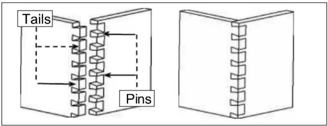
HALF-BLIND DOVETAILS
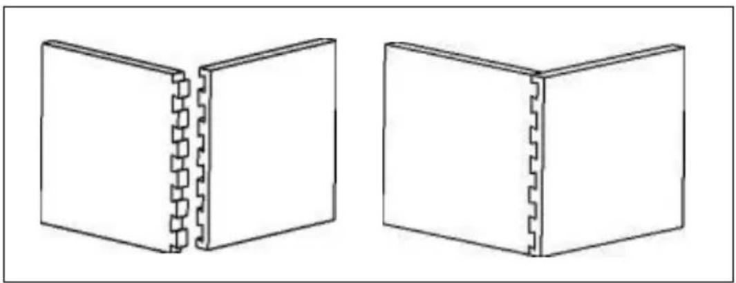
RABBETED HALF-BLIND DOVETAILS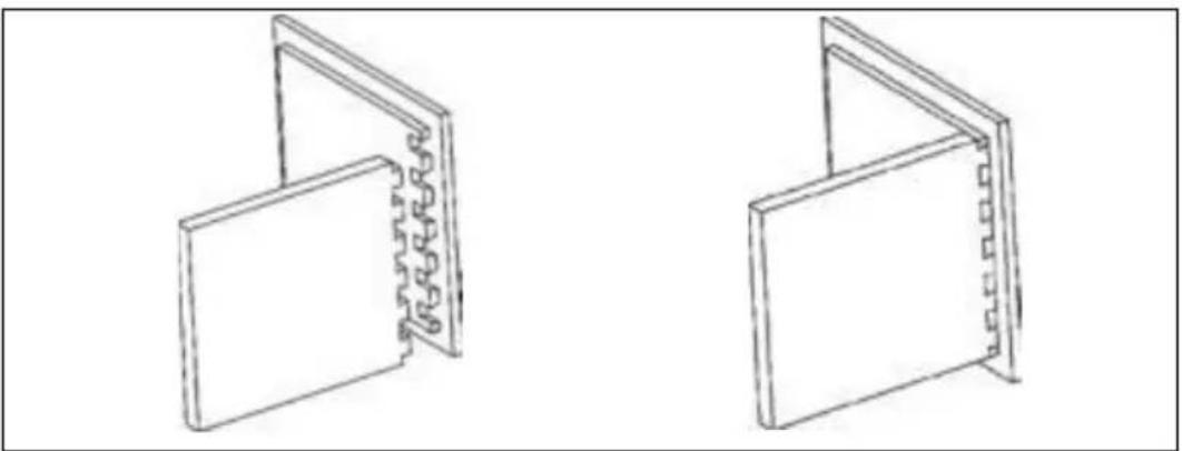
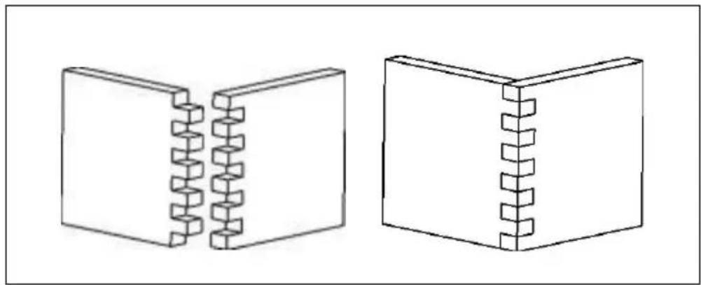
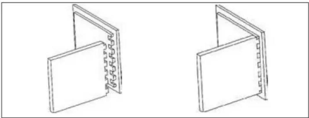
BOX (FINGER) JOINT
A similar joint, called a box or finger joint, has straight protrusions called fingers on both boards. This joint is used on jewelry boxes and other small boxes. The box joint is strong because it has a large surface area for glue.
PRODUCT CAPABILITIES
The VEVOR 28104 series dovetail jig will help you cut these joints efficiently. An accessory kit will enable you to cut miniature versions of these joints for small gift boxes or cubbyhole drawers on a roll-top desk. The 28104 series also has the capability to cut more advanced joints (dovetails that skip pins, wood hinges, end-to-end joints, various types of angle joints, and joints with inlays).
The specific model capabilities are:
Jigs
28104-1 Dovetail Jig - half-blind
28104-3 Deluxe Dovetail Jig - through dovetail, box joint, half-blind, and sliding dovetails.
JIG OVERVIEW
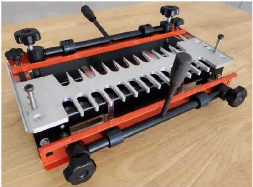
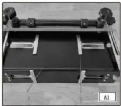
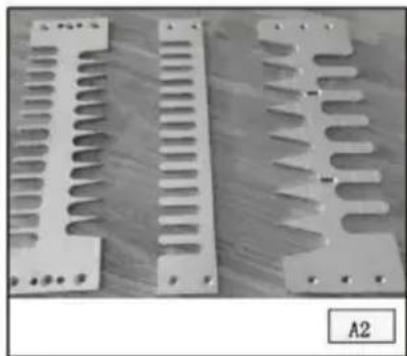
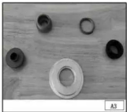
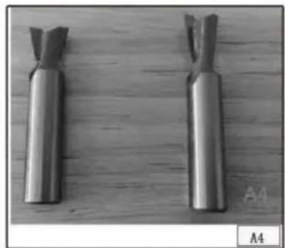
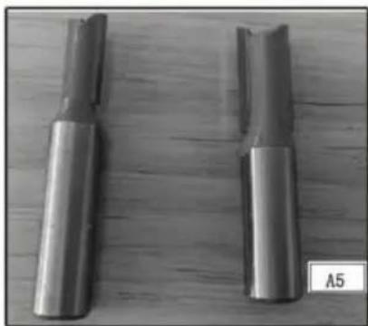
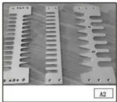
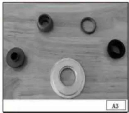
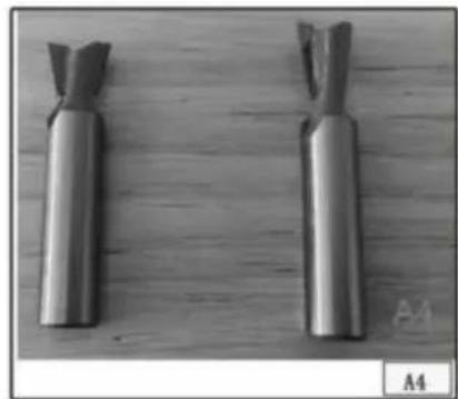
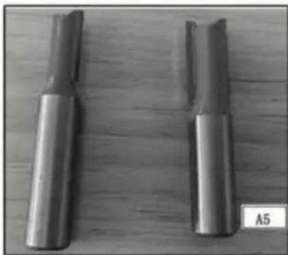
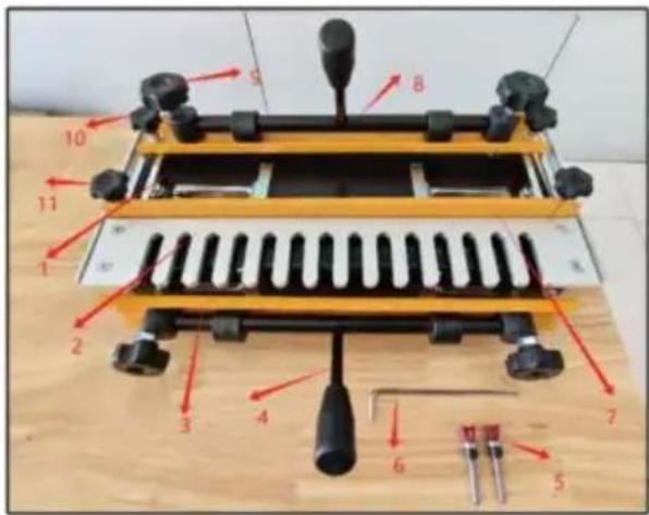
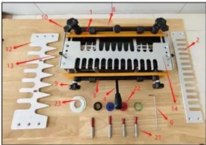
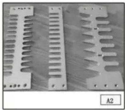
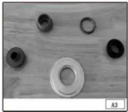
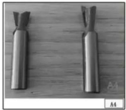
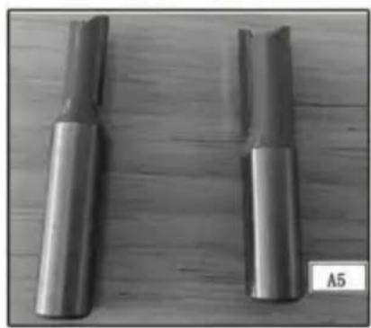
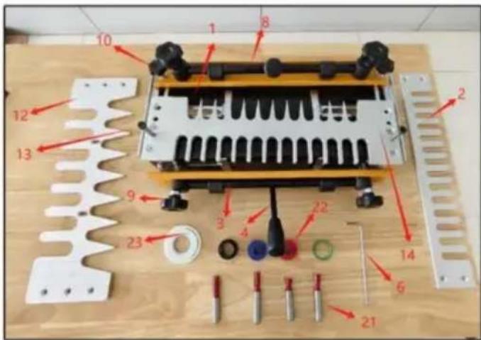
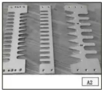
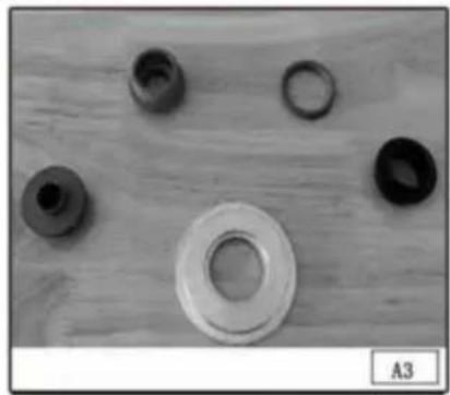
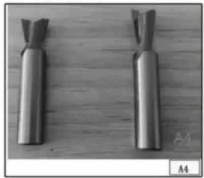
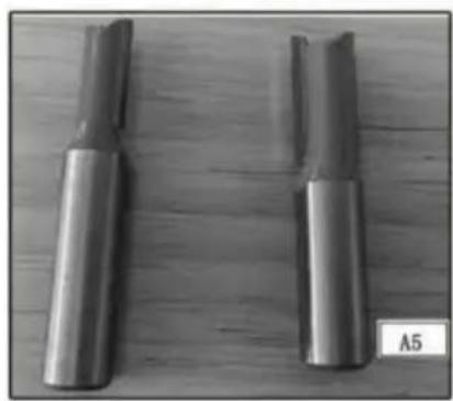
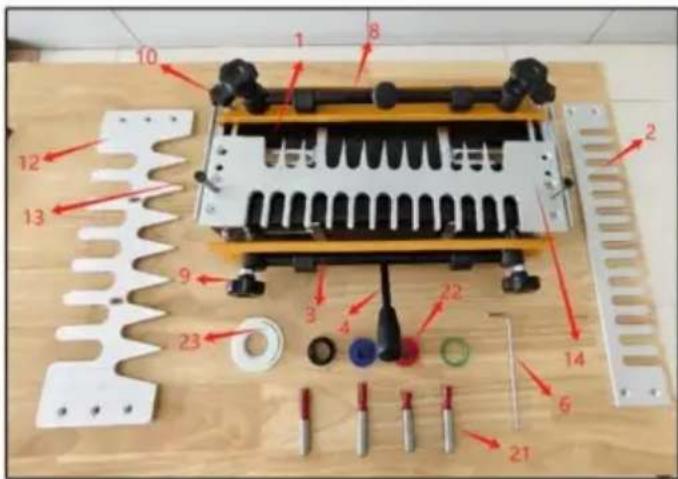
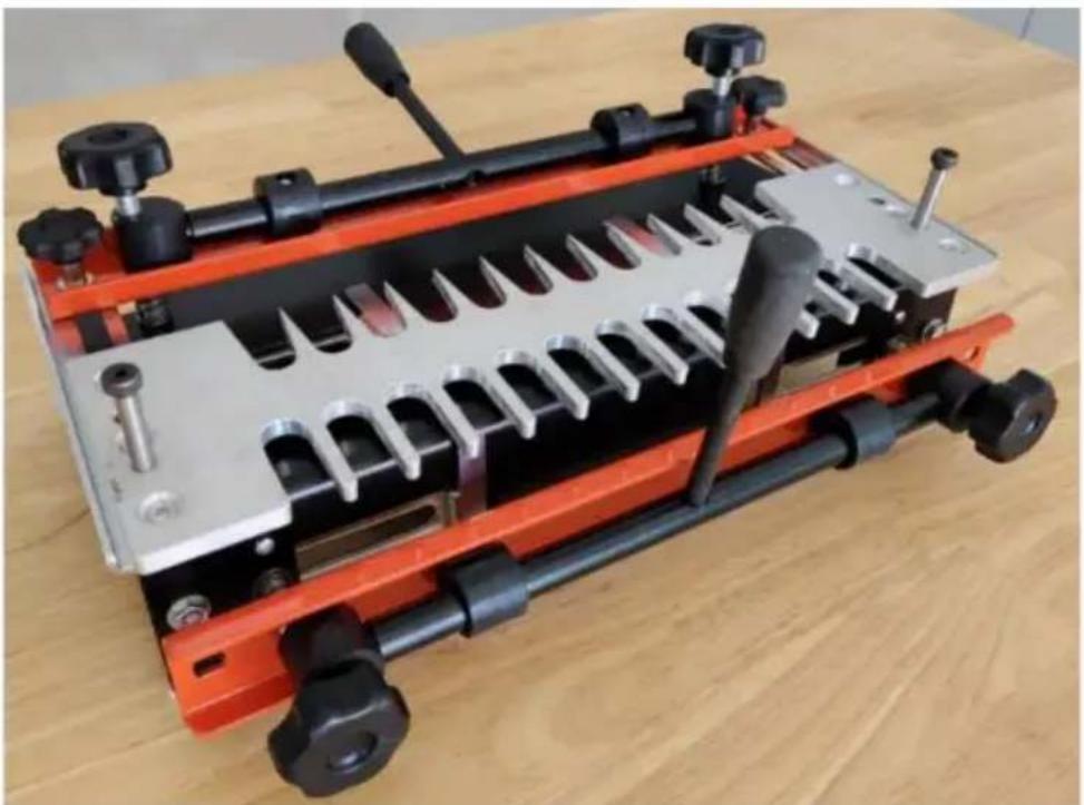
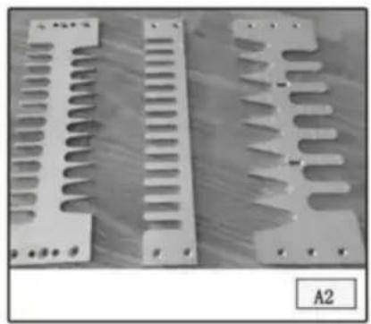
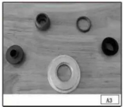
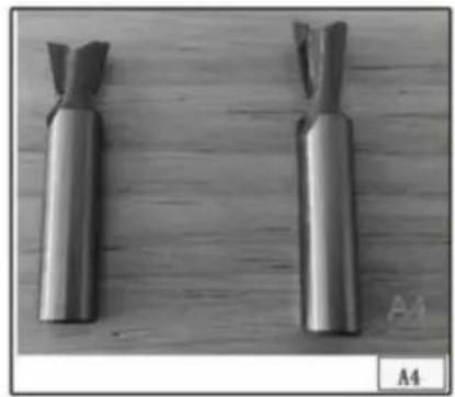
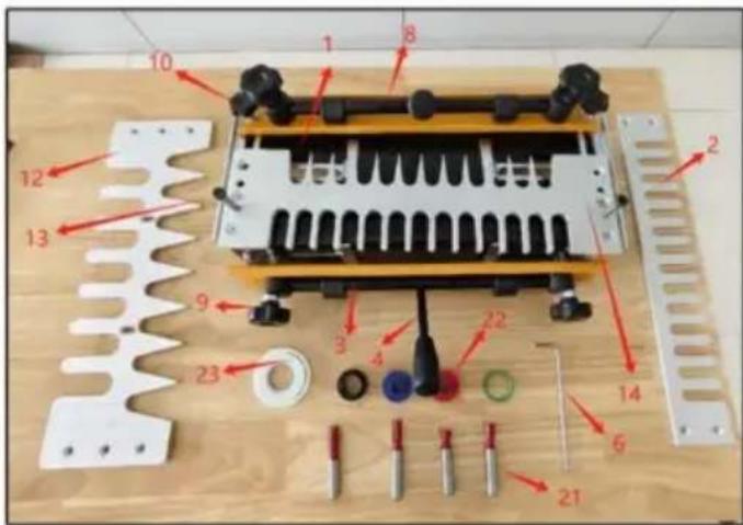
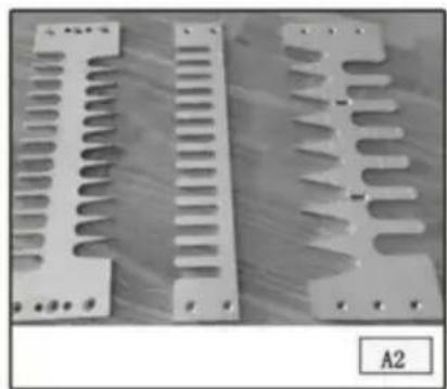
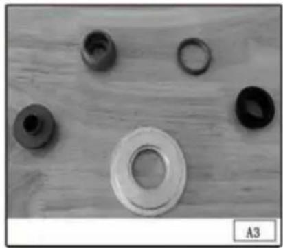
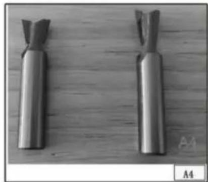
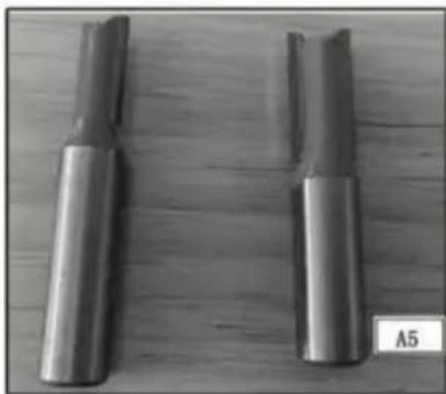
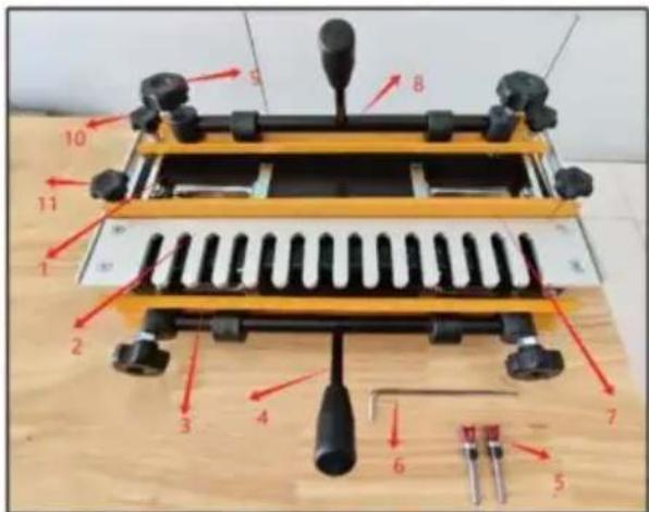
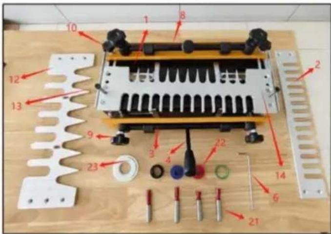
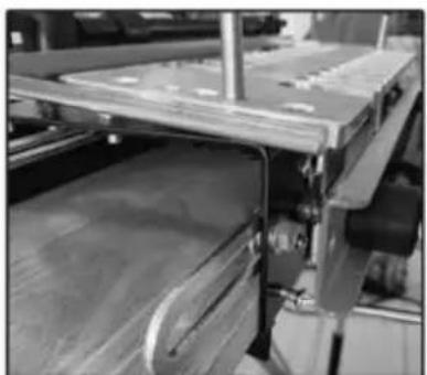
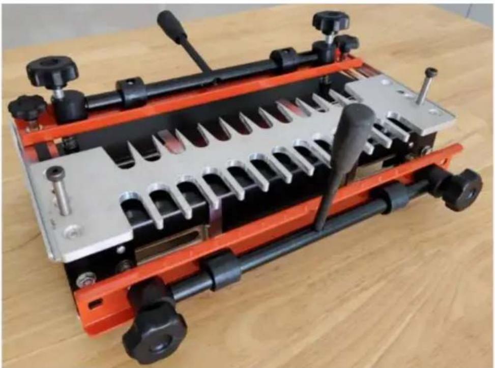
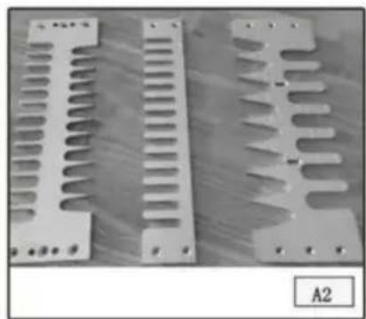
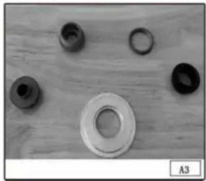
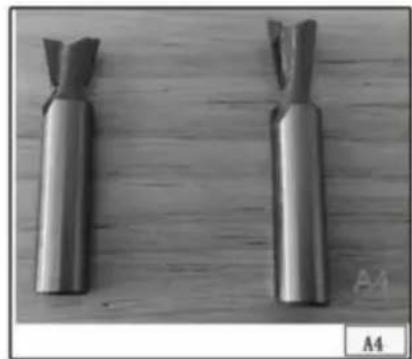
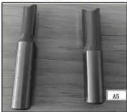
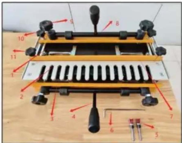
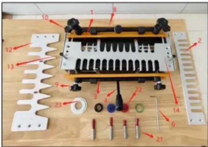
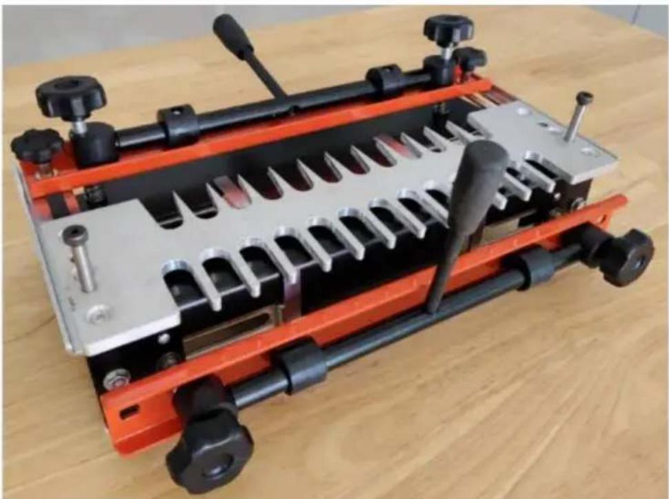
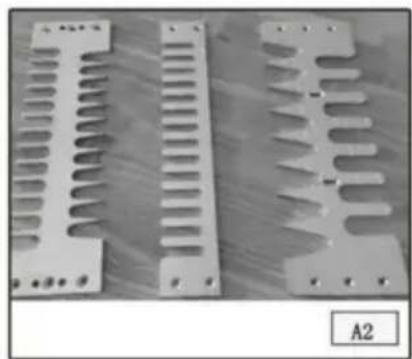
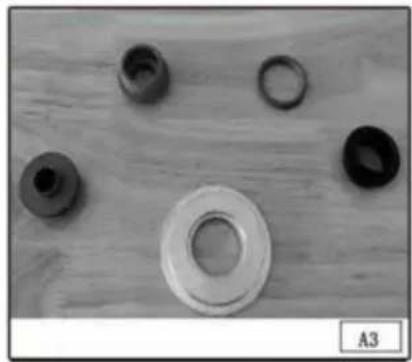
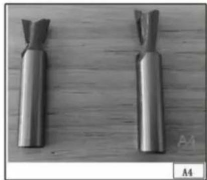
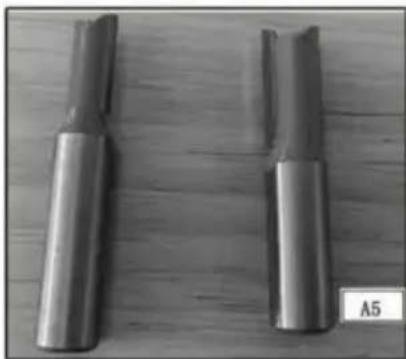
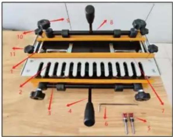
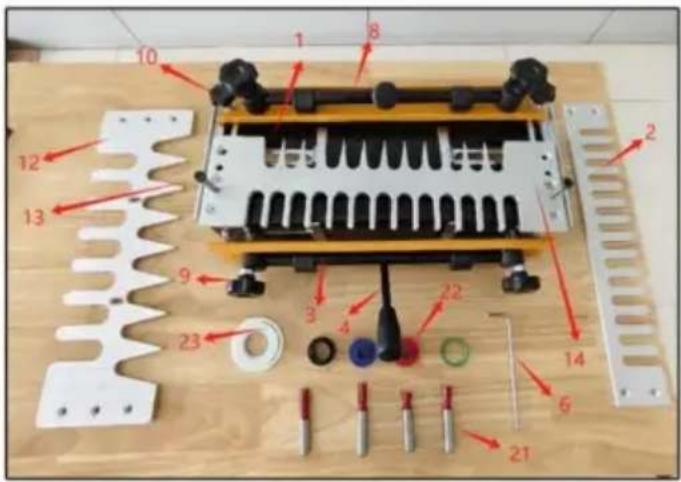
The 28104 series dovetail jigs come equipped with an easy-to-mount, heavy-duty steel base (A) Fig. A1 featuring a clamping system designed to hold wood and minimize board slippage during cuts. Troubleshooting tips (B) are provided on each side of the base. Three different machined aluminum templates (Fig. A2) can be used on the jig system to create all joints described in this manual. The fingers on each template are used in combination with the template guides (Fig. A3) to guide the router in the proper motion. Additionally, each template aids in setting proper board alignment and router bit depth. Dovetail bits and straight bits (Figs. A4 and A5) are used with this jig system.
CARTON CONTENTS
DOVETAIL JIGS
28104- 1
28104-3
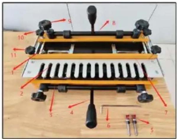
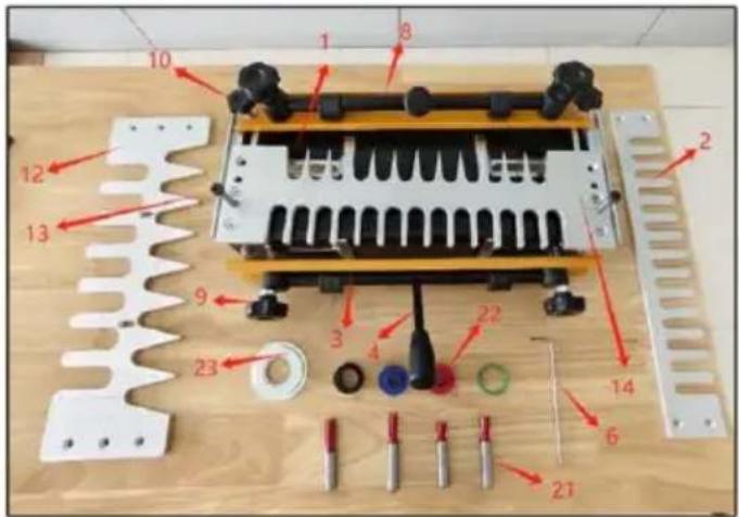
- Base
- 1/2Half-blind& Box Joint Template
- Pressing plate
- Handle
- Dovetail Bit
- Hexagonal wrench
- Positioning board
- Clamping rod
- M10 * 100 long pole handle
- M8 short pole handle
- M8 middle pole handle
- Clamping rod seat
- Spring
- Support plate L/R
- T-shaped nut
- M6 * 10 countersunk cross
- φ 8 flat pad
- Base 2.1/2 Half-blind & Box Joint Template
- Pressing plate
- Handle
- Hexagonal wrench
- Clamping rod
- M10 * 100 long pole handle
- M8 short pole handle
- 1-inch through dovetail template
- φ8 * 45-M6 plug bolt
- 1/2 through dovetail template
- Dovetail bit and straight tenon drills
- Three types of shaft sleeve nuts
- Positioning disk
Accessory
| 1/2" through dovetail template11 "through dovetail template * 11/2" Half-blind Template * 11/2 "* 10.3 *stɪlæight tenon drills11/2 "* 1/2" * 30 straight tenon dri1/2 "* 13.5 * 7 ° Dovetail Bit *1/2 "* 15 * 12 ° Dovetail Bit *Base group * 1Pressing plate * 2Positioning board * 1Support board * 2Clamping rod * 2Spring * 4Handle * 2M10 long pole handle * 4M8 long pole handle * 2M8 short pole handle * 2Clamping shaft seat * 4T-shaped nut * 4φ 8 gasket * 4M6 * 10 countersunk screws * 4Positioning bolt * 2Positioning disk * 1M30 * 1.5 knurled nut * 13/4 "shaft sleeve * 15/8 "shaft sleeve * 11 "shaft sleeve * 1 | Base * 1Pressing plate * 2Positioning board * 1Galvanized support plate * 2Clamping axis * 2Spring * 41/2" Half-blind Template* 1Handle * 2M10 long pole handle * 4M8 long pole handle * 2M8 short pole handle * 2Clamping shaft seat * 4T-shaped nut * 41/4 Dovetail Bit* 28 gaskets * 4M6 * 10 countersunk screws * |
ADDITIONAL TOOLS REQUIRED
The router that you use with this jig
must accept the VEVOR template guides supplied with the jig. (Adapters and sub-bases are available for most routers.) It must have a 1/2" collet for use with the 28104-3 jig, and a 1/4" collet for use with the 28104-1 jig.
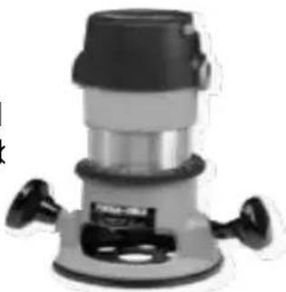
NOTE: While the jigs and accessory kits include
router bits and template guides to make the basic dovetail joints, additional router bits are required to make box joints.
MOUNTING INSTRUCTIONS
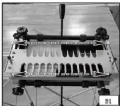
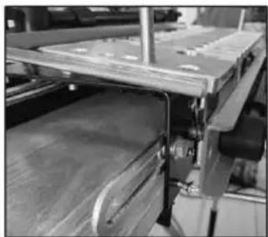
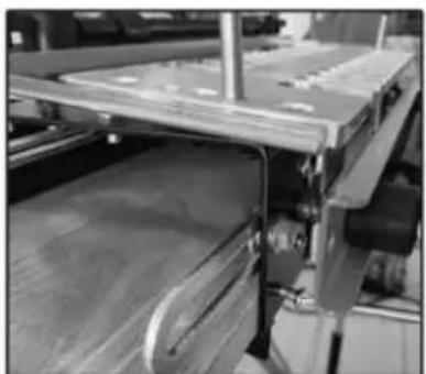
NOTE: Always mount your jig to a solid work surface.
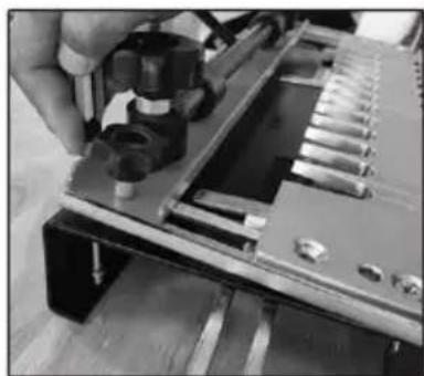
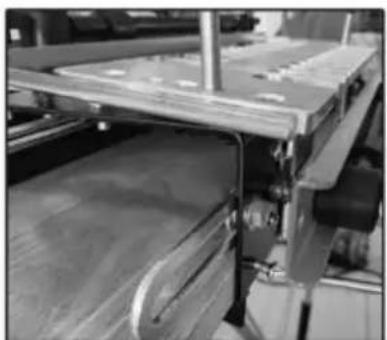
You can mount your jig permanently (Fig. B1) by using the pre-drilled holes (A) on each side of the base, or you can mount the base to your work surface using clamps (Fig. B2).
OPERATION
Mount your workpiece in the jig properly. If the workpiece is not secure, it can be damaged when it moves.
The jigs utilize two mounting positions for workpieces - horizontal and vertical. Some joints require both, while others require the use of a scrap board in the horizontal position (upper clamp) and the workpiece in the vertical position (lower clamp).
Position your workpiece correctly left-to-right to produce symmetrical and tight-fitting joints.
Tear-out from the router bit can be reduced when scrap wood is positioned properly against the workpiece.
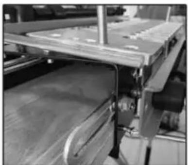
CLAMPS
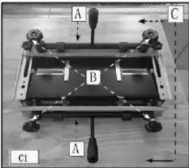
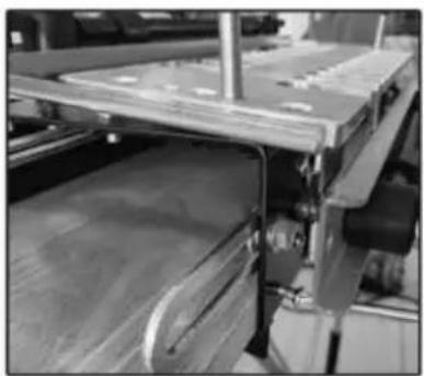
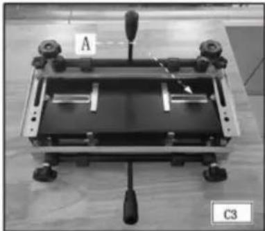
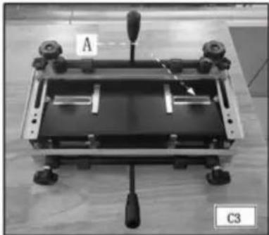
The 28104 series jigs are equipped with two cam-action clamps (A) Fig. C1 with knobs (B)
To adjust for workpiece thickness, and levers (C) for quick clamping and releasing of workpieces.
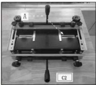
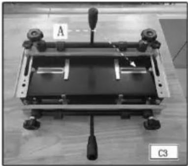
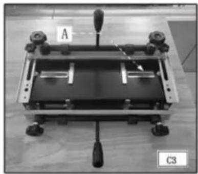
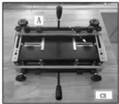
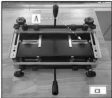
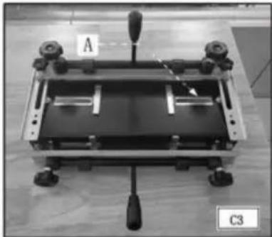
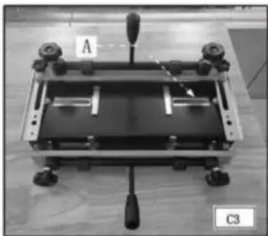
NOTE: Use a scrap board (A) Fig. C2 to prevent misalignment (A) Fig. C3.
TEMPLATE MOUNTING
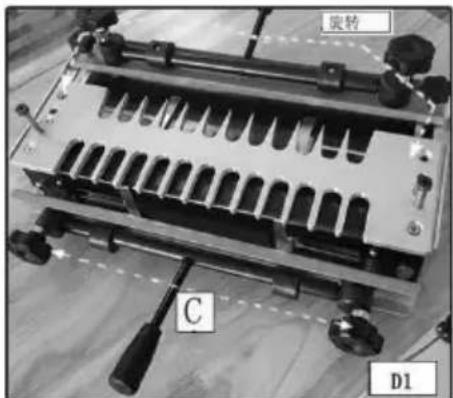
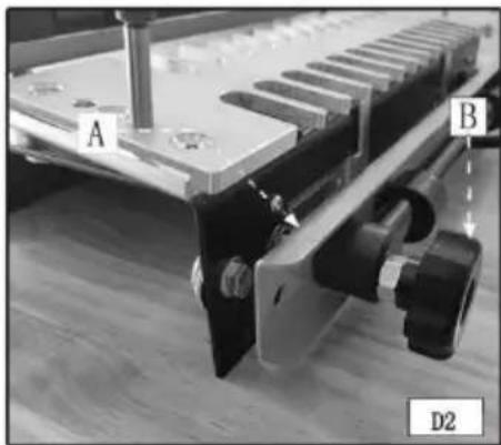
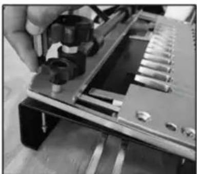
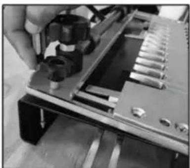
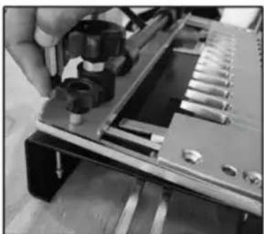
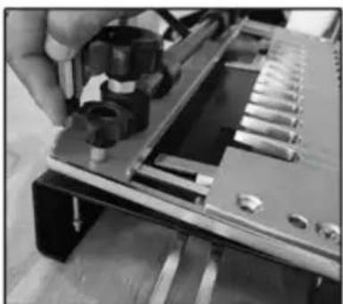
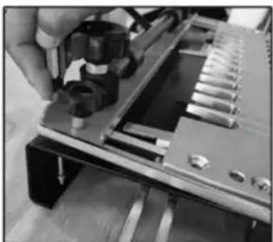
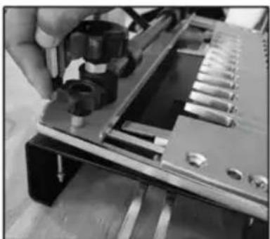
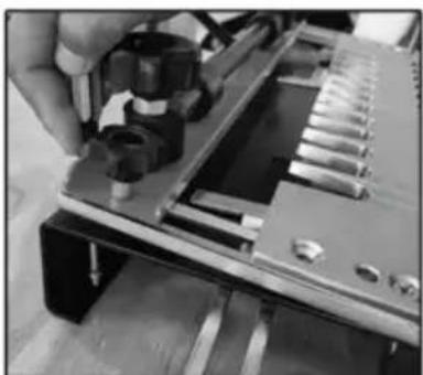
You can mount the templates in two positions on the jig(s) which allows the production of multiple types of joints with each template. To reverse a template, loosen the template knobs (C) Fig. D1, remove the template (B) from the base, rotate it 180 degrees horizontally, replace it on the base, and tighten the template knobs.
TEMPLATE SUPPORT
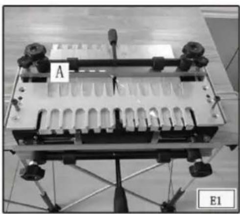
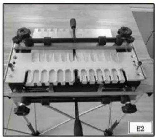
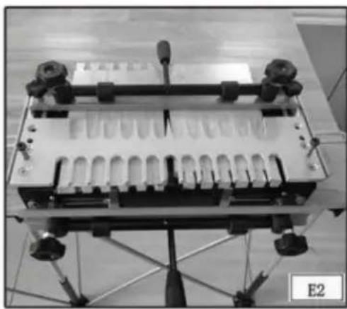
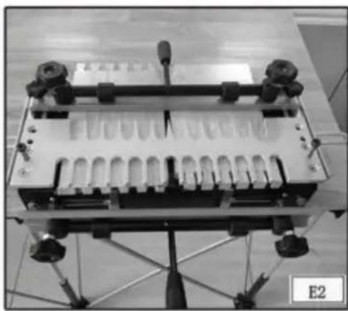
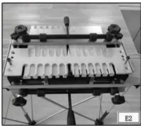
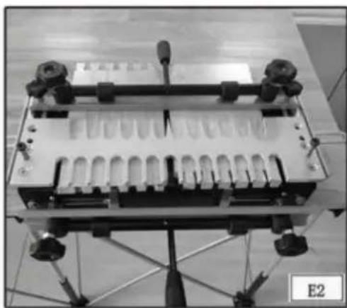
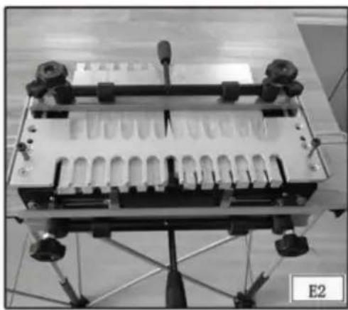
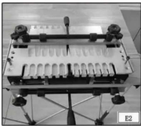
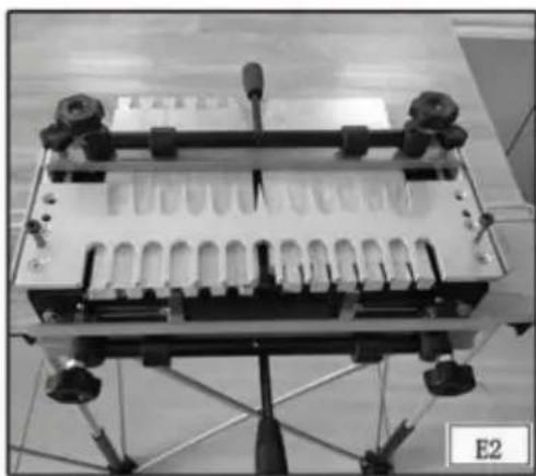
For every type of joint, place wood in the top clamp, whether a workpiece or a scrap piece, to provide support for the router on the template. You can add extra support by inserting a second board (A) Fig. E1 (of the same thickness) in the top clamp to ensure that the template is parallel to the base across its length. This practice works very well for narrow workpieces.
Supported Unsupported
POSITIONING THE WOOD
You must position the workpiece correctly to produce attractive symmetrical joints. Use the offset guides to consistently position the workpiece for optimal alignment and symmetry.
Step 1 -Clamp the workpiece (or spacer board) (A) Fig. F1 in the horizontal position. The position is not critical, but the workpiece must not extend beyond the front edge of the base.
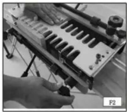
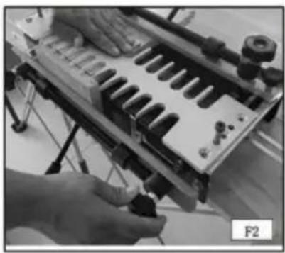
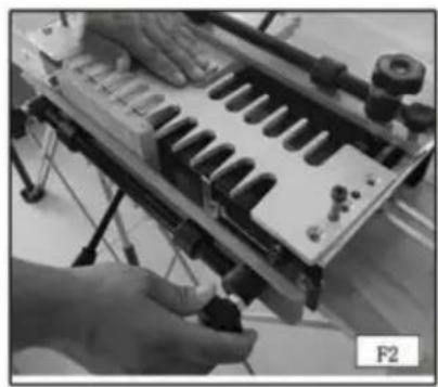
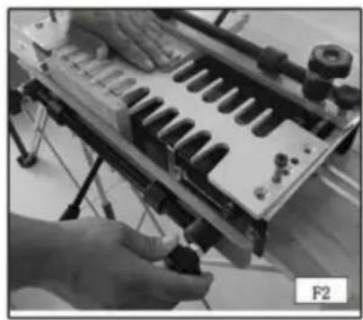
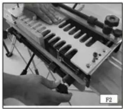
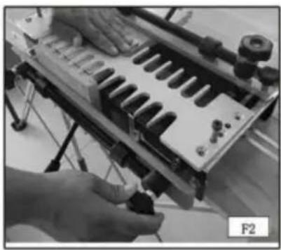
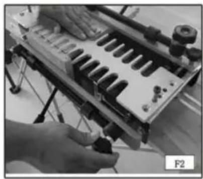
Step 2 -Mount the template (Fig. F2) on top of the horizontal workpiece. Use positioning bolts to fix the template and base in place, and tighten the template knobs with the other.
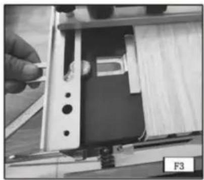
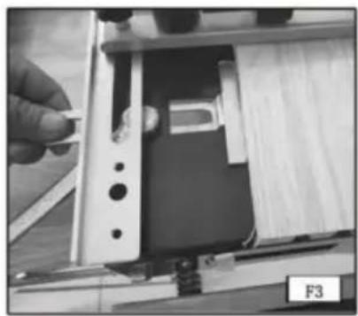
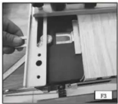
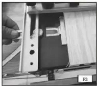
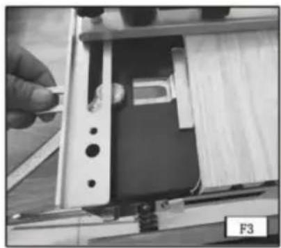
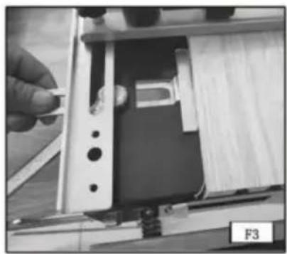
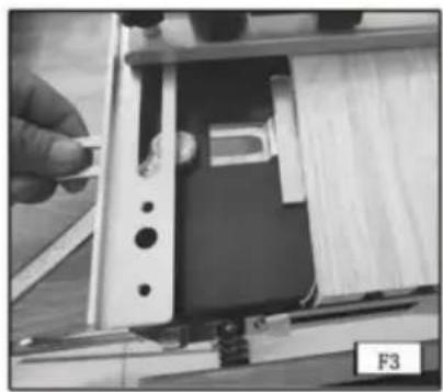
Step 3 -Loosen the left offset guide (A) Fig. F3 with the hex wrench (E) and move it to the far left position.
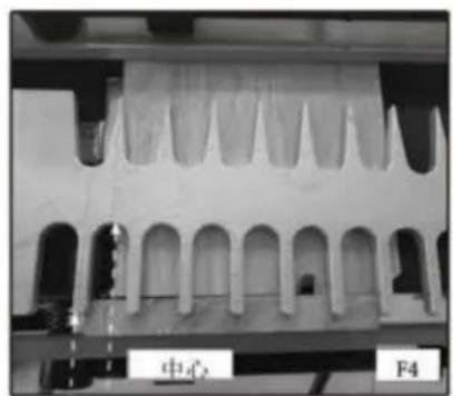
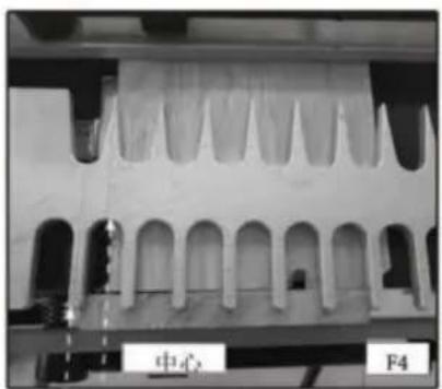
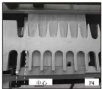
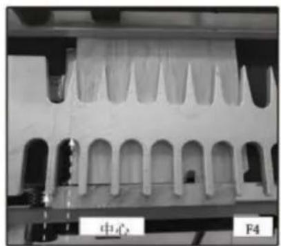
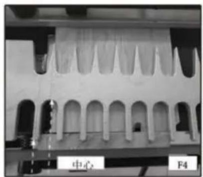
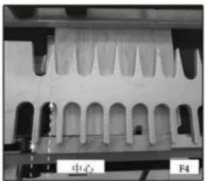
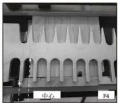
Step 4 -Align the vertical workpiece (A) Fig. F4 flush against the bottom side of the template. Center and clamp the workpiece between the farthest finger to the left and the nearest finger to the right of the template.
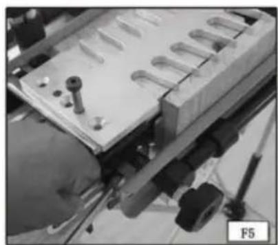
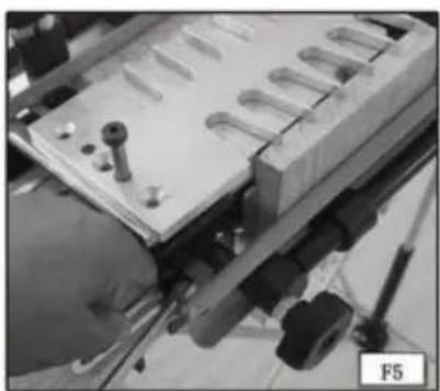
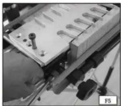
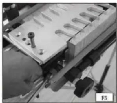
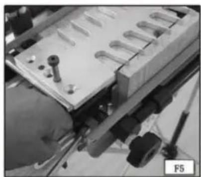
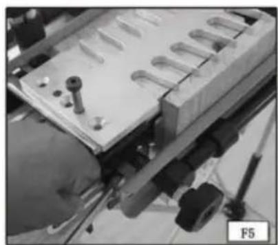
Step 5 -Move the left offset guide (A) Fig. F5 to the right so that it is flush against the vertical workpiece (B). Tighten the left offset guide with the wrench (C).
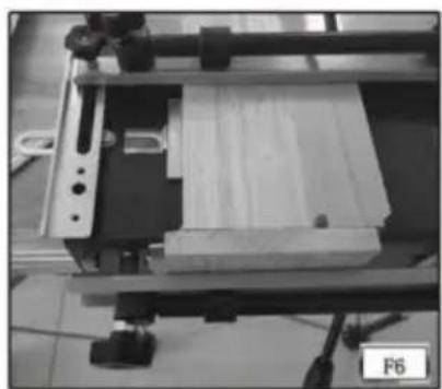
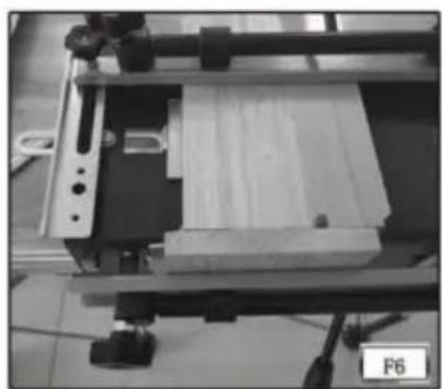
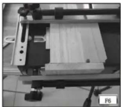
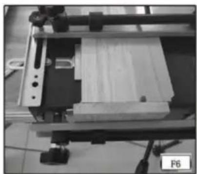
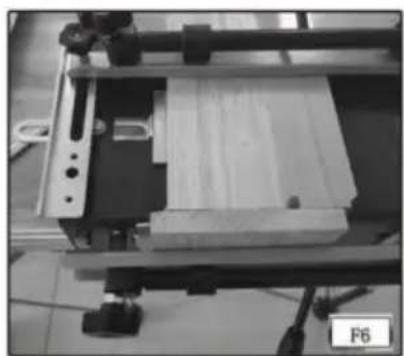
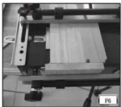
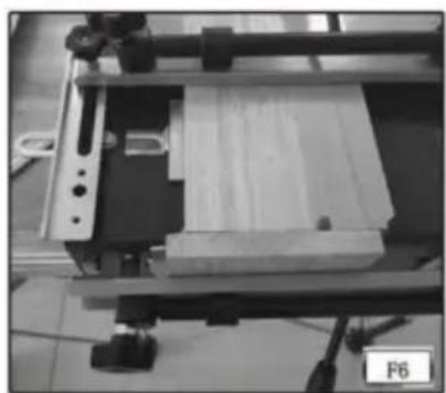
Step 6 - Unclamp the horizontal workpiece and slide it forward so that it is flush against the vertical workpiece and flush against the left offset guide (Fig. F6). Tighten the template with 4 cross bolts.
Step 7 - Remove the 2 positioning bolts.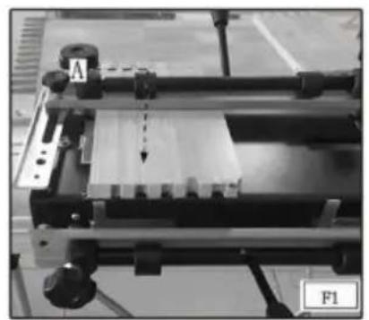
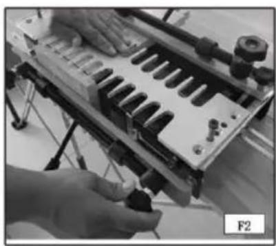
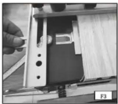
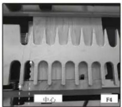
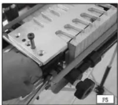
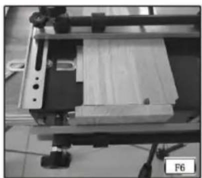
NOTE: The template has been removed for clarity. After tightening the 4 cross bolts on the template, you must remove the 2 positioning bolts.
HALF-PINS VS. HALF-TAILS
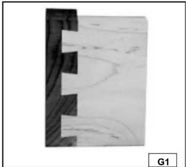
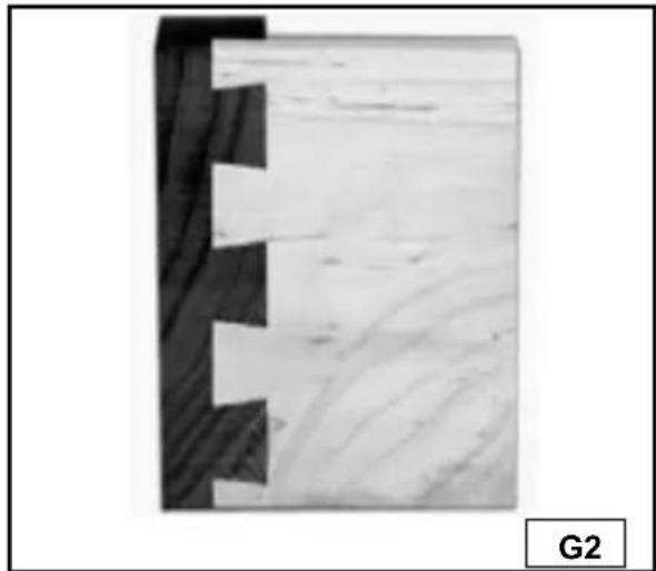
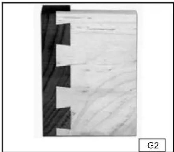
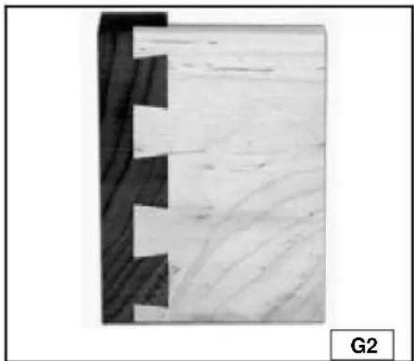
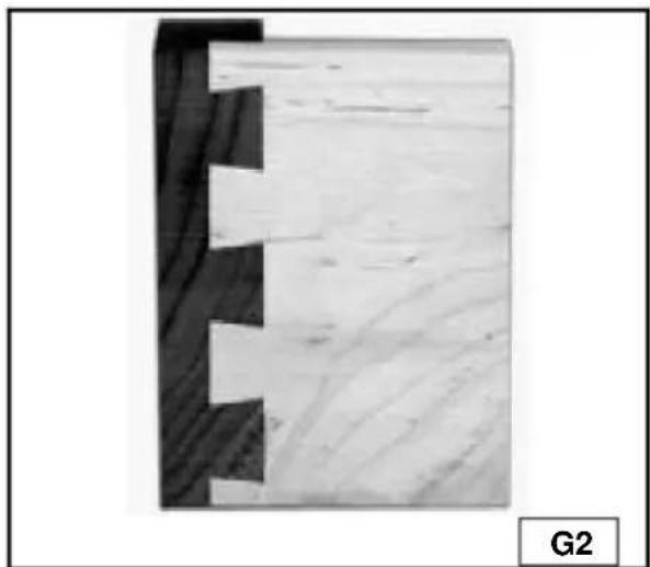
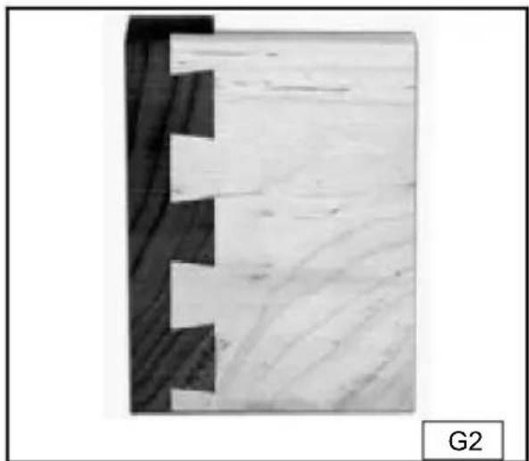
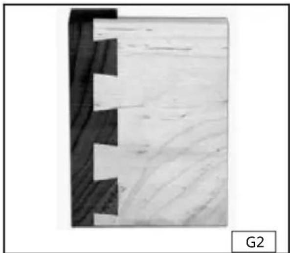
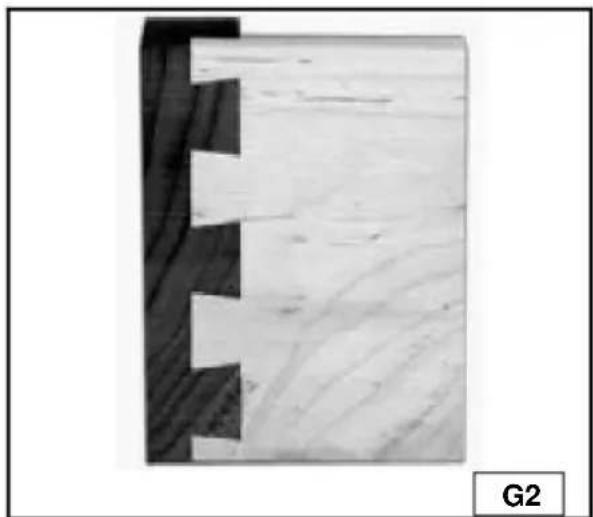
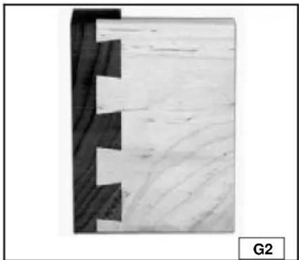
Traditionally, dovetails have half-pins cut on both ends (Fig. G1). Half-tails will be just as strong, but will not be as attractive (Fig. G2). If your joints are half-tails and you want half-pins, move the vertical board 1/2" either left or right, then move the horizontal board accordingly. The procedure is the same with the 28104-1 Miniature template, except that you move the boards 1/4".
TEAROUT REDUCTION
Tearout is unwanted splintering of the wood fibers that occurs when a router bit enters, exits, or skims the edge of wood and is common to all dovetail jigs. Tearout cannot be eliminated, but it can be reduced by the insertion of additional scrap wood against the workpiece.
ALIGNING THE TEMPLATES
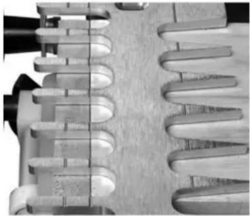
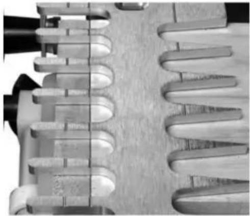
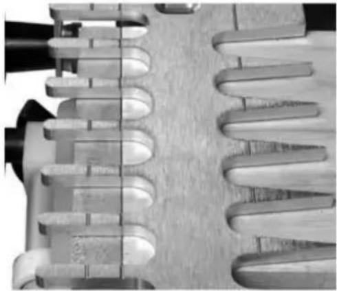
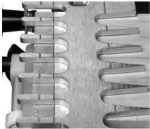
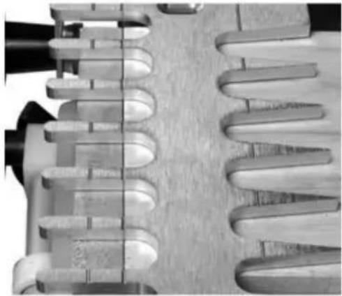
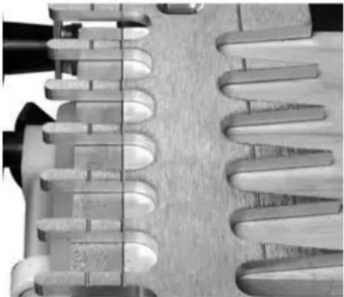
For proper operation, you must align the templates correctly from front to back. The 28104 series jigs have alignment lines to help you align the templates without measuring. Some templates have one line (Fig. H1) while others have several lines to produce multiple types of joints (Fig. H2). VEVOR has scribed icons on the templates to indicate which lines go with which joints.
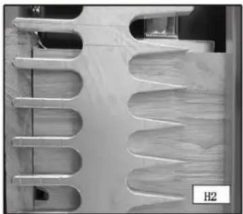
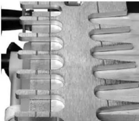
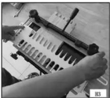
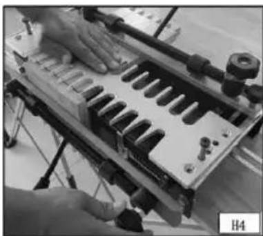
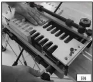
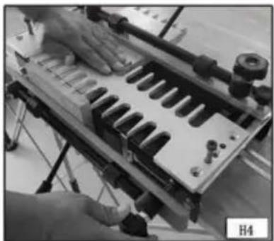
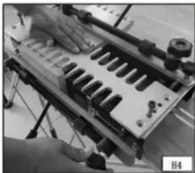
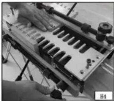
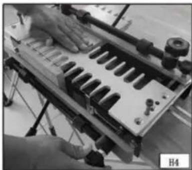
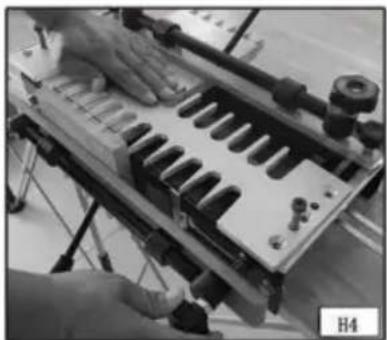
Adjust the templates front-to-back until the alignment line is directly over the point where the horizontal board and the vertical board meet. NOTE: To be accurate, lean over the template and look straight down to align the lines (Fig. H3). For the joint to be produced correctly, loosen the knobs on both sides of the template, align the lines, hold the template flat with one hand, and tighten the knobs with the other (Fig. H4).
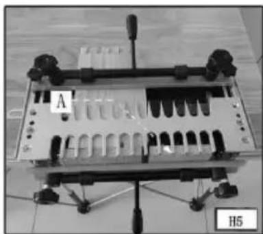
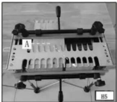
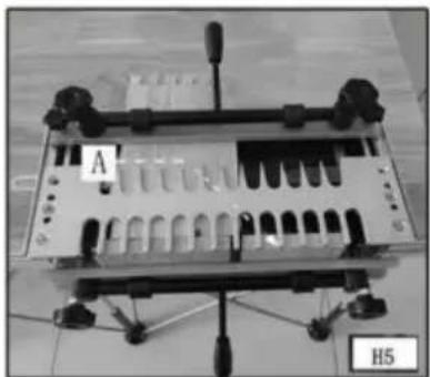
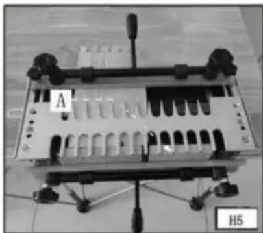
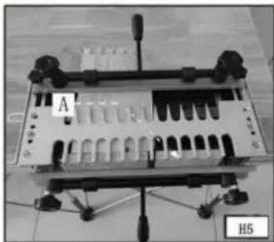
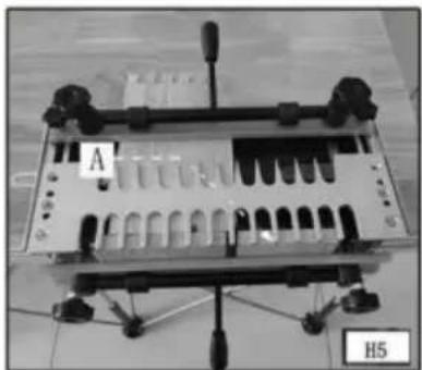
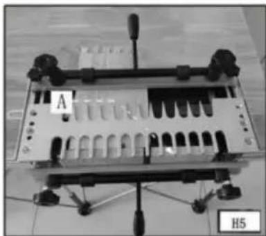
NOTE: To help align both ends of the template when you are using a narrow workpiece, mount an additional piece of wood (of the same thickness) on the far right (A) Fig. H5.
TEMPLATE GUIDES
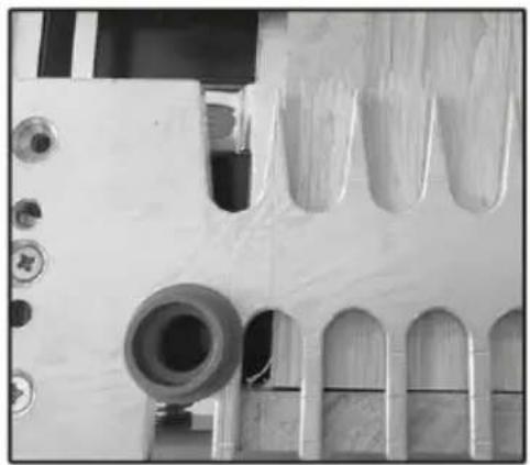
Use the correct template guides provided with this unit to guide the router against the template finger. To determine the proper guide for a given joint, place the template guide in the slot on the left side of the corresponding template. The guide should have a snug fit in the slot.
WOOD PREPARATION
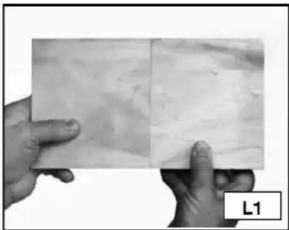
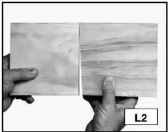
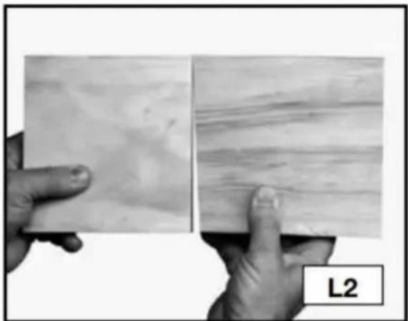
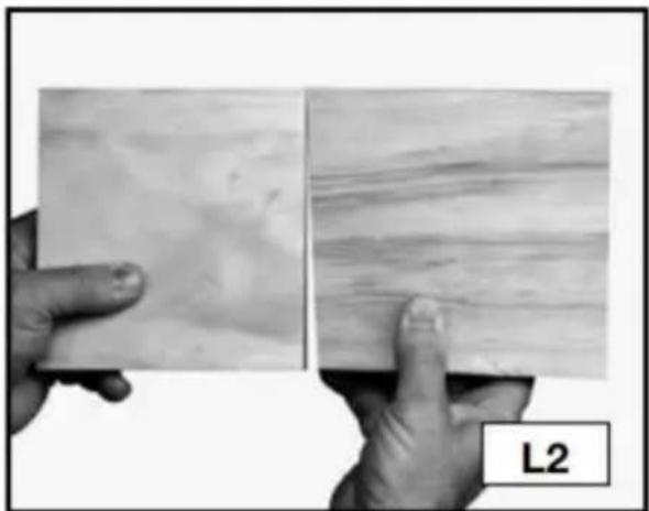
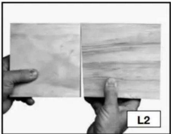
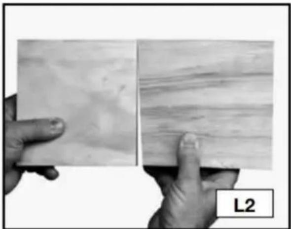
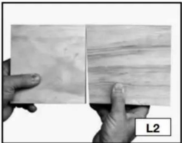
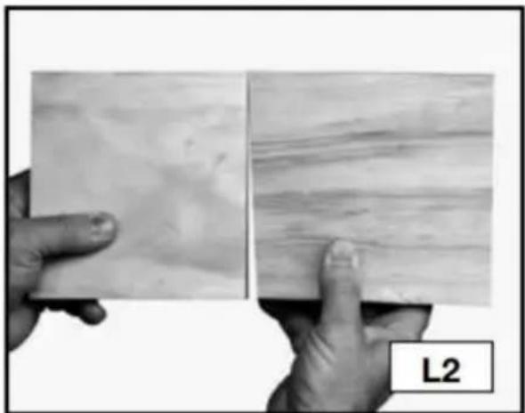
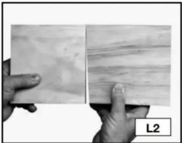
Properly preparing the materials for your project is the key to good-looking and tight-fitting joints. You must cut your wood at perfect right angles (Fig. L1). Cuts that are off even one degree will not align correctly (Fig. L2). Also, your workpieces must be flat and not cupped.
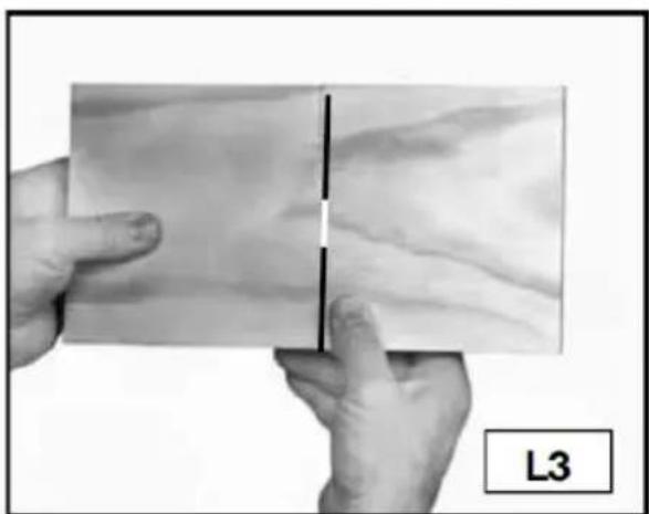
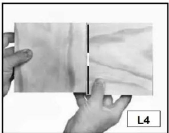
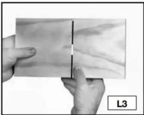
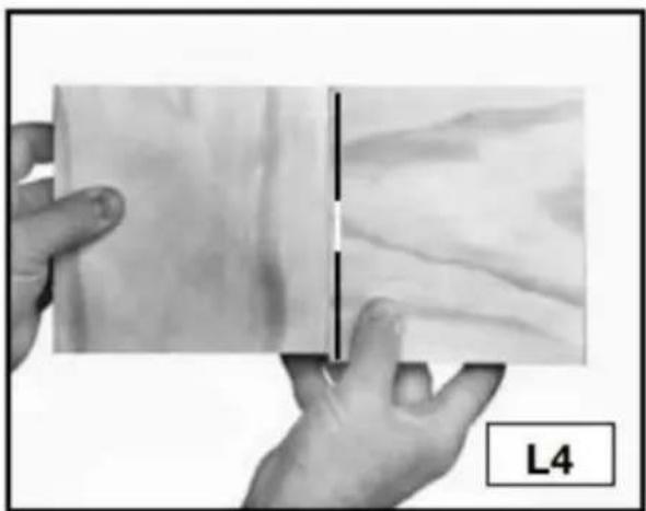
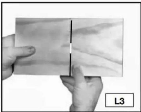
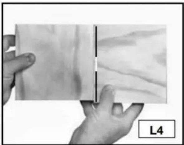
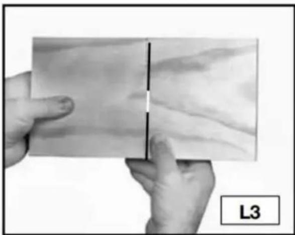
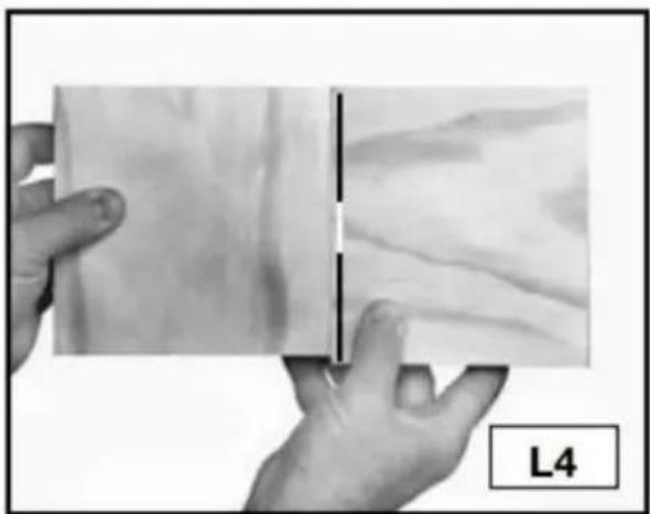
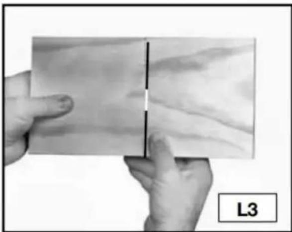
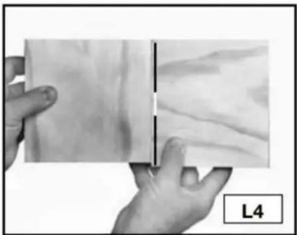
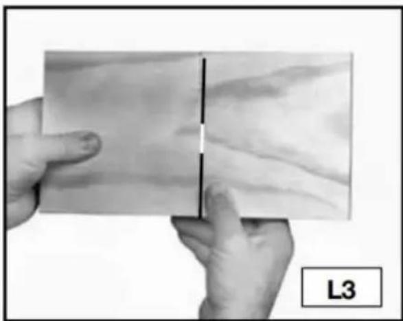
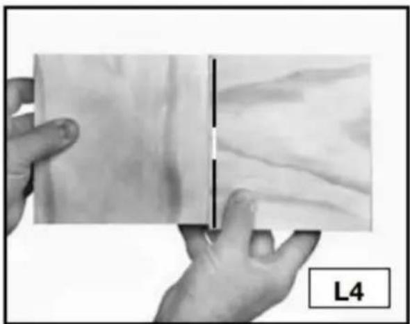
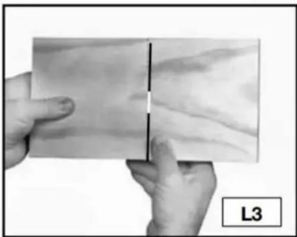
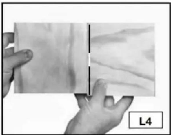
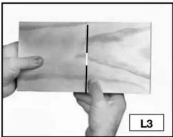
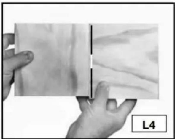
Orient your wood so that end grain is joined to end grain (Fig. L3) to make the joint strong. Using the long grain (Fig. L4) in the workpiece will result in a weak joint.
BOARD THICKNESS
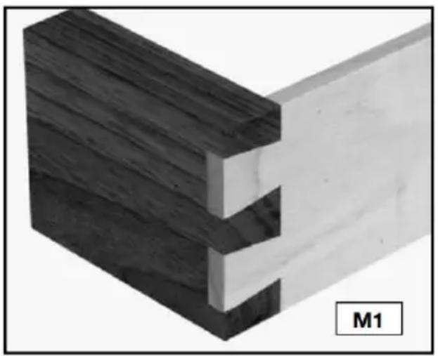
NOTE: You can join two workpieces that are different thicknesses (Fig. M1).
The clamps on the 28104 series jigs will hold wood from 1/4" to 1-1/8" thick. Use the following information as a guide to help you decide the thickness of wood for your projects.
Standard through dovetails……Tail Board Range……1/4" to 1" Pin Board Range……: 1/4" to 3/4"
Half-blind dovetails…… Standard and Miniature 1/2" to 1-1/8"
BOARD LENGTHS
The 28104 series dovetail jigs are capable of making joints up to 12". For through dovetails and box joints, cut your workpieces to the same length as the outside dimension of your final project.
To calculate the length of the half-blind tail board, take the inside dimension of the final project and add the router bit depth of cut. If the tail board has a half-blind on both ends, double the added dimension. The length of the pin boards (drawer front) remains the same.
PROJECT LAYOUT
Keeping track of the outer and inner face of each workpiece and how the different parts mate with each other is very important.
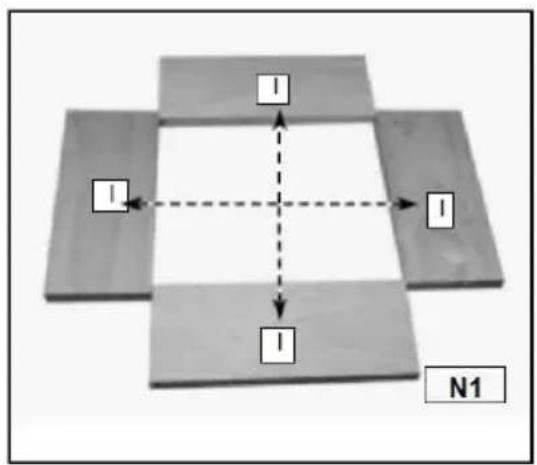
Step 1 - Lay out the workpieces facedown and label the inside faces with an "I" (Fig. N1).
Step 2 - Label the corners "A", "B", "C", and "D" (Fig. N2).
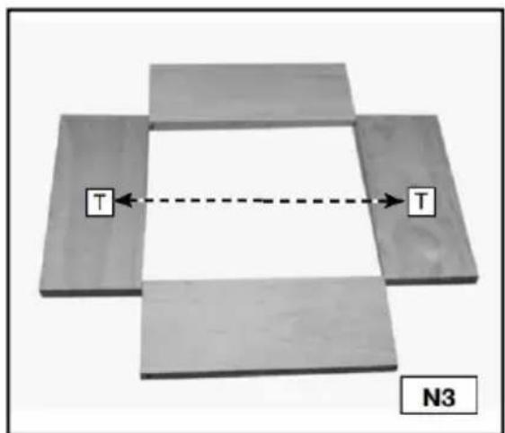
Step 3 - Label the tail boards (drawer sides) with a "T" (Fig. N3).
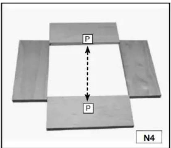
Step 4 - Label the pin boards (drawer fronts) with a "P" (Fig. N4).
![graph TD A["A"] --> B["B"] A --> C["C"] A --> D["D"] B --> C B --> D C --> D style A fill:#f9f,stroke:#333 style B fill:#ccf,stroke:#333 style C fill:#cfc,stroke:#333 style D fill:#fcc,stroke:#333 style_N2[" N2 "]](/content/2026/04/738107/images/a2511d5b80522c338cd081fd0b8eeeb1d1a773137c1de42c8f2fab859734297f.jpg)
DRAWERS
Tips for making drawers:
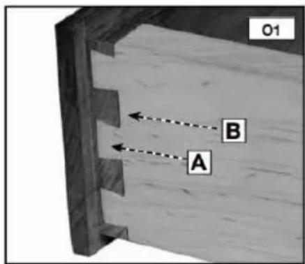
Tails (A) Fig. O1 are cut into the sides of the drawers, while pins (B) O1 are cut into the fronts and backs of drawers.
You can use either solid wood or plywood for the drawer bottoms (A) Fig. O2. Insert the bottoms in a groove along the bottom of the fronts and sides. Allow the drawer bottom to be free-floating (without glue) to allow for seasonal expansion and contraction.
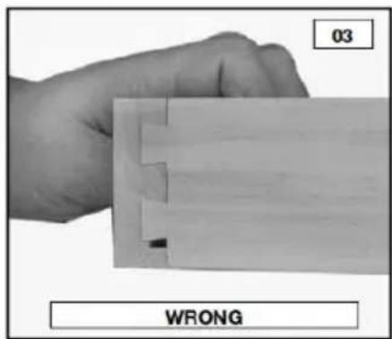
The grooves can go all the way to the ends of the boards if the joints are half-blind dovetails. To accomplish this, position the groove so that it runs through one of the tails on the side (Fig. O2). You will have to stop the grooves on through dovetails or box joints before they reach the end of the board to prevent them from being seen (Figs O5 and O6).
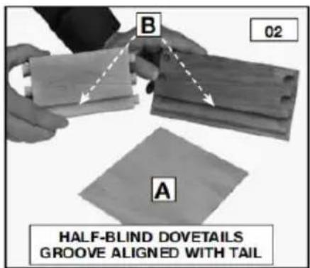
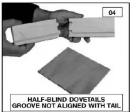
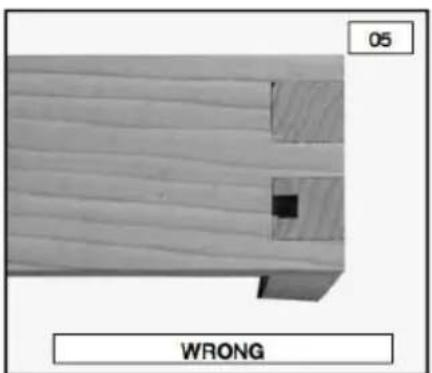
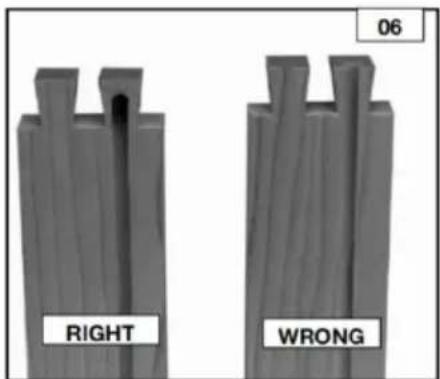
BASIC JOINTS
THROUGH DOVETAILS
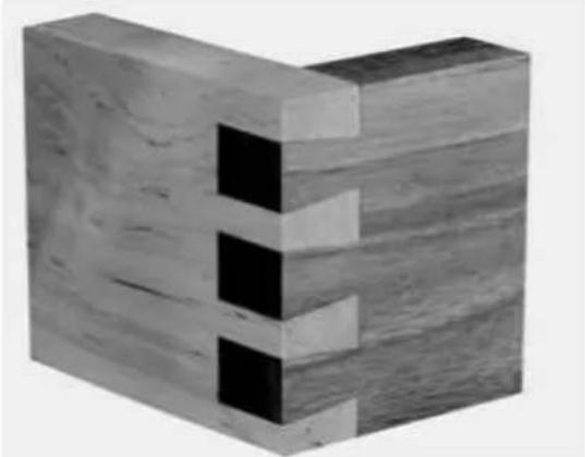
The through dovetail has a look that is visually appealing, especially in boxes and chests.
NOTE: For through dovetails, use the 28104-3 accessory kit. Cut both the pins and tails in the vertical position. Cut the tails first. Use two routers (if possible) - one for pins and the other for the tails - to make the process quicker and easier.
ITEMS NEEDED
• Through Dovetail and Box Joint Template • 1/2"*13.5*7° Dovetail Bit - 1/2"*10.3*1" Straight Bit, • 3/4" O.D. Template Guide, (with dovetail bit) - 5/8" O.D. Template Guide, (with straight bit) - Template Guide Lock Nut,
CUTTING THE TAILS
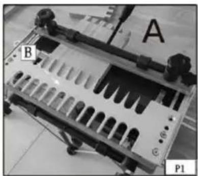
Step 1 - Clamp a spacer board (A) Fig. P1 (equal to the thickness of your pinboard) in the upper clamp. Mount the through dovetail template (B) on the base with the "tails" side facing you.
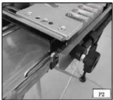
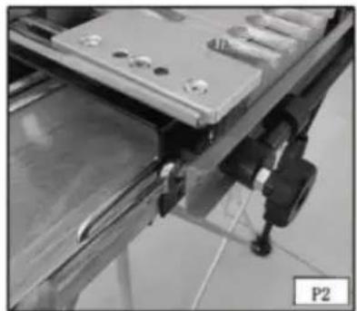
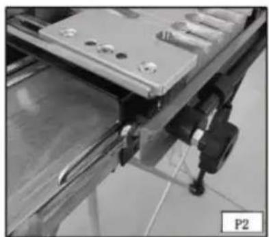
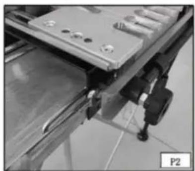
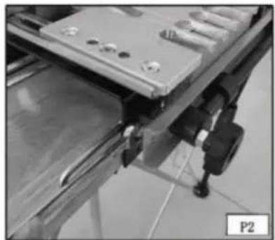
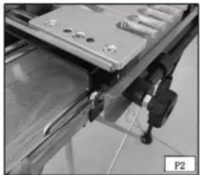
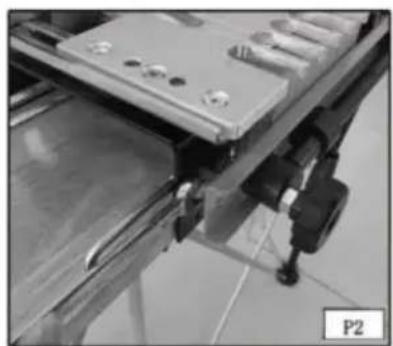
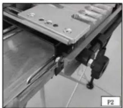
Step 2 - Move the offset guide (A) Fig. P2 to the far left.
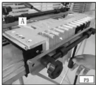
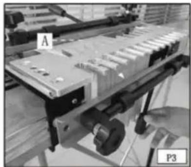
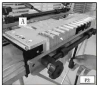
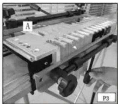
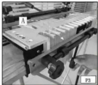
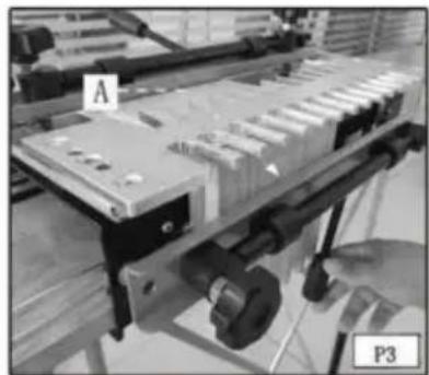
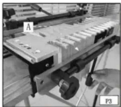
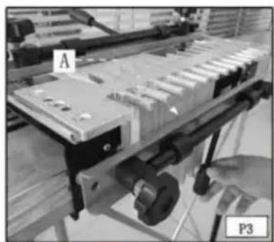
Step 3 - Clamp the tailboard (A) Fig. P3 in the lower clamp with the outside surface of the board facing the jig.
(See the section "POSITIONING THE WOOD" in this manual.)
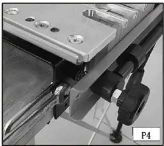
Step 4: Reposition the offset guide (A) Fig. P4 flush to the vertical board and secure it.
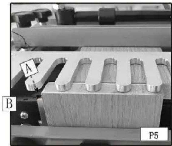
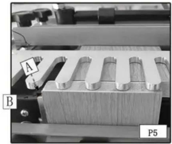
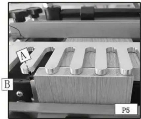
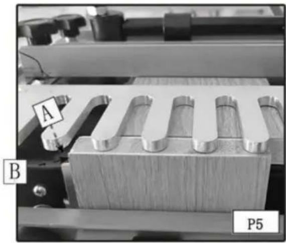
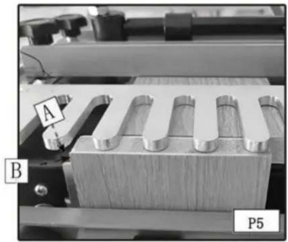
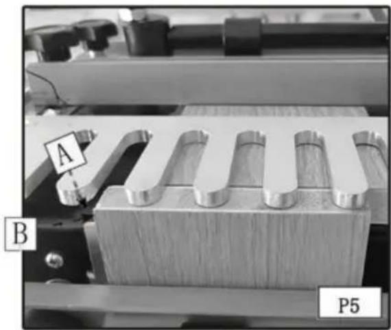
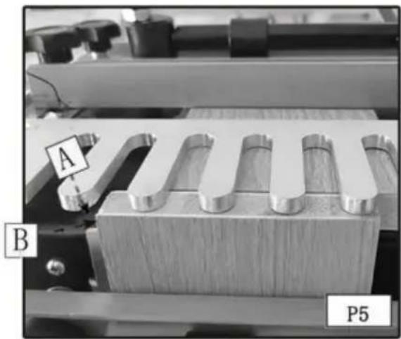
Step 5: Reposition the scrap board (A) Fig. P5 so that it is flush with the rear edge of the vertical board (B).
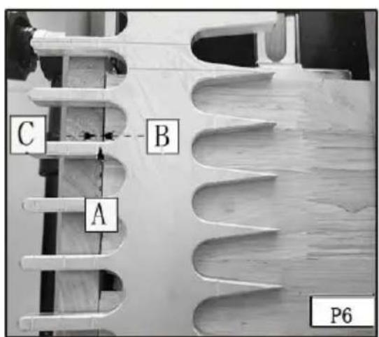
Step 6: Align the template using the "tails/box" line (A) Fig. P6 with the line formed where the scrap board (B) and the vertical board meet (C) and secure it.
Step 7: Mount the dovetail bit and 3/4" template guide on the router and set the router bit depth.
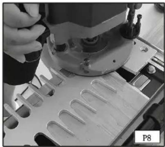
Step 8: Rout along the template fingers (Fig. P8). When the cut is complete, remove the vertical board.
NOTE: If you prefer for your pins to protrude slightly for easier sanding, adjust your router for a slightly deeper cut. Once your optimum depth has been achieved, adjust the bit height guide with a 3/8" wrench.
CUTTING THE PINS
NOTE: If the pin board is not the same thickness as the tail board, replace the scrap piece in the horizontal clamp with a scrap board the same thickness as your tail board.
Step 1: Remove the template and rotate it 180 degrees. Clamp the pin board in the lower clamp, flush against the left offset guide with the outside of the board facing away from the jig.
Step 2: Align the "pins" line (see the arrows) Fig. P10 on the template with the line formed where the scrap board and pin board meet and tighten the template in place.
Step 3: Mount the straight bit and the 5/8" template guide on the router and set the router bit depth (Fig. P11).

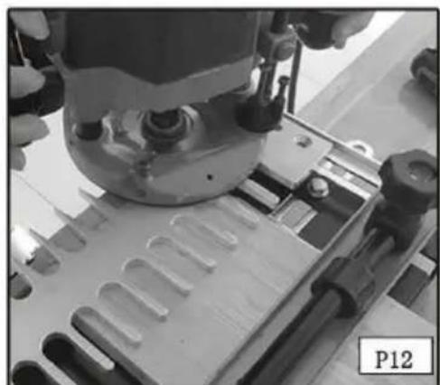
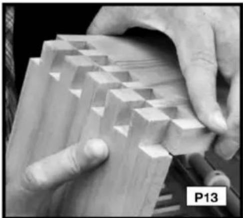
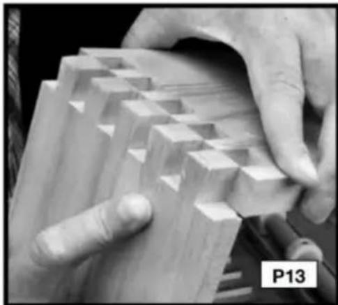
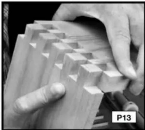
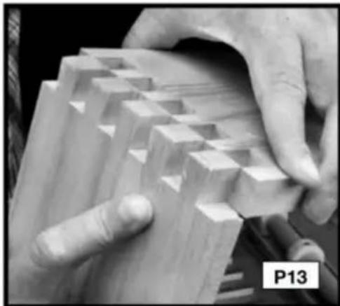
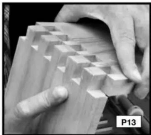
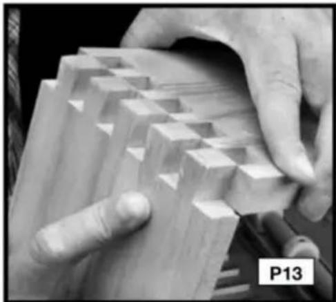
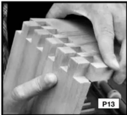
Step 5: Rout between the fingers of the template (Fig. P12). Step 6: Remove the pin board and check the fit with the tailboard (Fig. P13).
THROUGH DOVETAIL TROUBLESHOOTING
For joints that are too loose, move the template toward you slightly. For joints that are too tight, move the template away from you slightly.
HALF-BLIND DOVETAILS
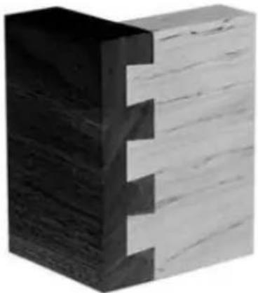
The half-blind dovetail is one of the most common types of joints and is the ideal choice for drawer construction. In typical half-blind drawer construction, the joint is not visible from the front and is invisible when the drawer is closed.
NOTE: For miniature half-blinds, use the 28101 accessory kit.
Use scrap wood until you are comfortable with the jig.
You can cut half-blind pins and tails simultaneously on the 28104 series jigs.
Mount the correct offset guides - black for the standard and silver for the miniature.
ITEMS NEEDED
• Half-blind Dovetail Template • 1/4" x 15.4 x 13 Dovetail Bit • 3/4" O.D. Template Guide
CUTTING HALF-BLIND DOVETAILS
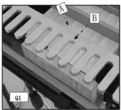
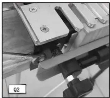
Step 1 - Clamp the pin board (drawer front) (A) Fig. Q1 in the upper clamp (horizontal mounting position) with the outside of the board facing the jig.
Step 2 - Secure the template (B) on top of the pin board. Ensure flatness by holding one hand on the template and using the other to tighten the template knobs.
Step 3 - Move the left offset guide all the way to the left.
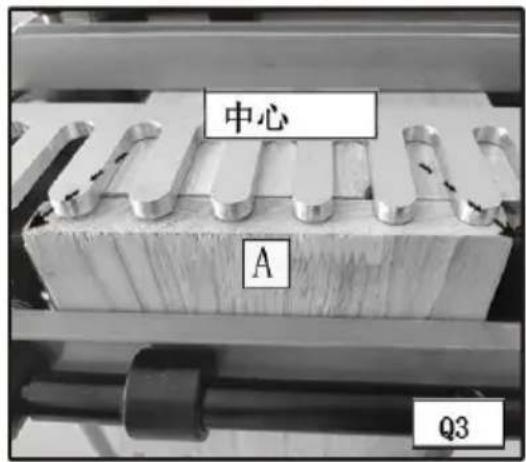
Step 4 - Clamp the tailboard (drawer side) in the lower clamp (vertical
position) on the left side of the base with the outside of the board facing the jig (A) Fig. Q3.
Step 5 - Center the board between the farthest finger on the left and the nearest finger on the right of the board.
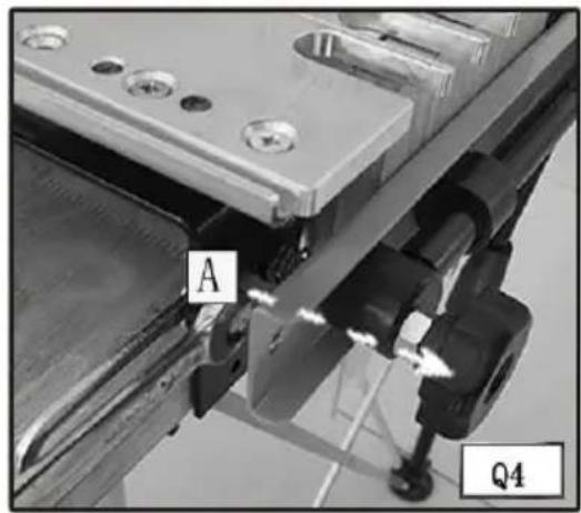
Step 6 - Move the left offset guide (A) Fig. Q4 flush against the vertical board (B) and secure it.
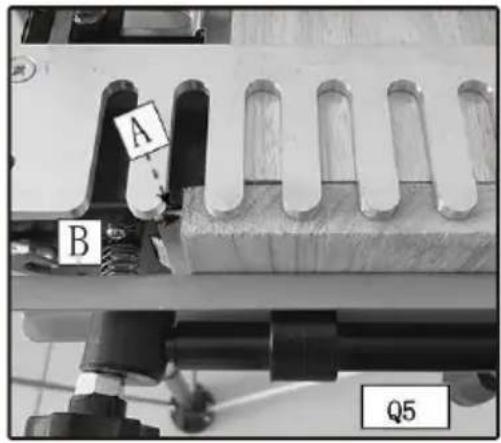
Step 7 - Reposition the pin board (B) Fig. Q5 so that it is flush against the offset guide (A) and the back edge of the vertical board (C).
Step 8 - Align the template lines with the intersection of the pin board (A) Fig. Q6 and tail board (B).
Step 9 - Set the router bit depth using the bit-depth guide (A) Fig.
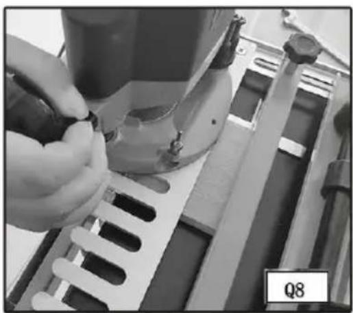
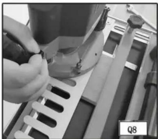
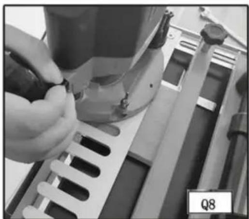
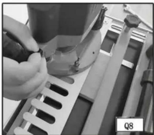
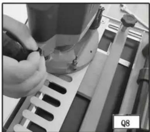
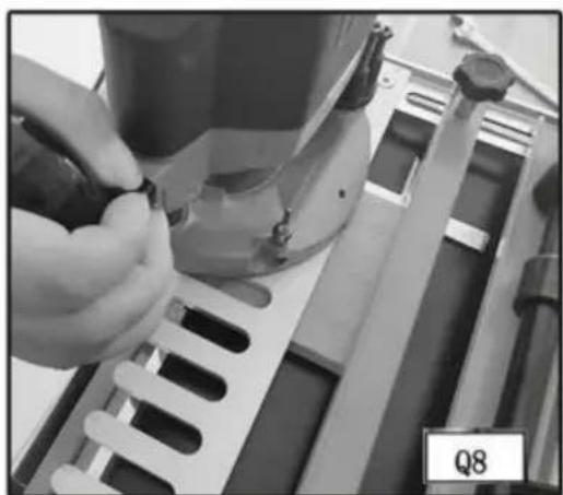
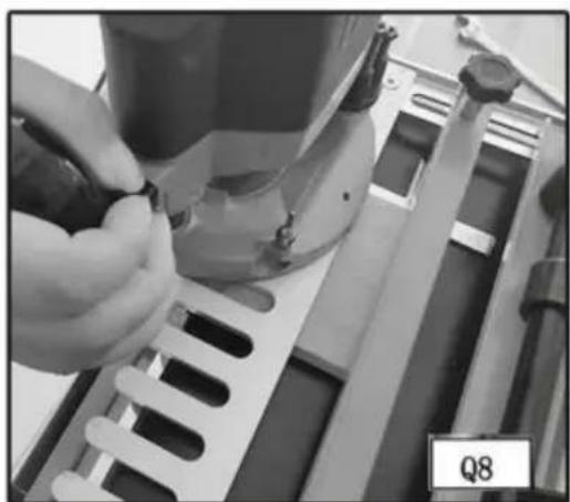
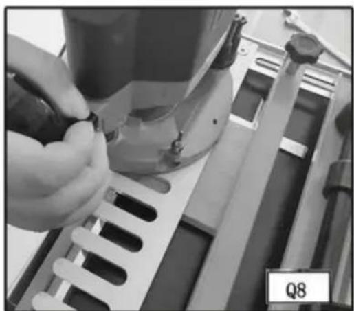
Step 10 - Climb cut (from right to the outer edge of the vertical board (Fig. Q8) to reduce tearout.
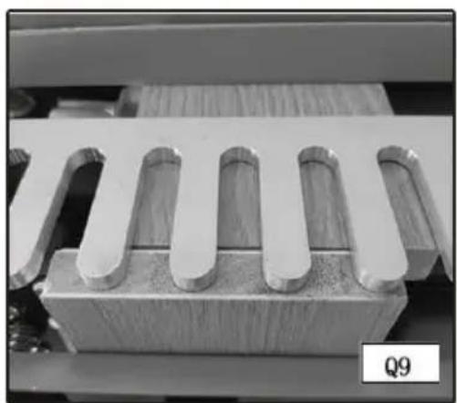
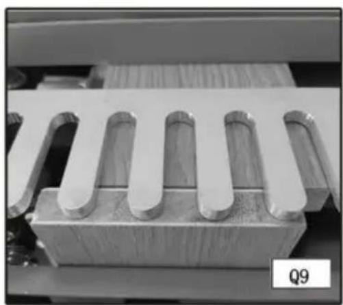
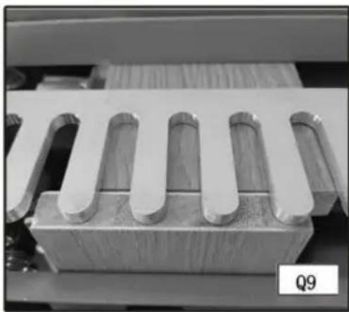
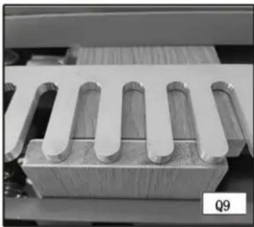
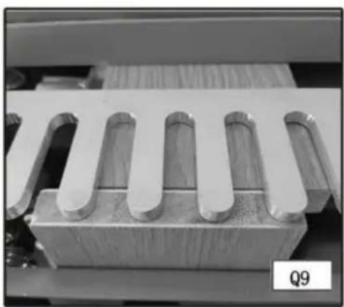
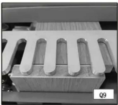
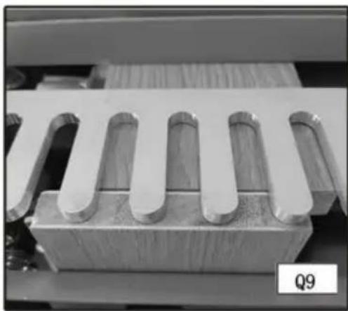
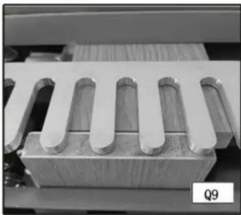
Step 11 - Rout along the fingers of the template (Fig. Q9). Remove the boards from the jig and test for fit.
FITTING AND TROUBLESHOOTING
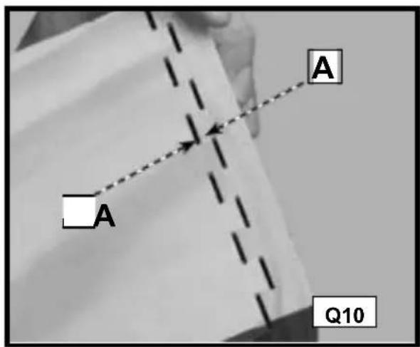
For joints that are too loose, adjust your router to make a deeper cut. (Measure the gap (A) Fig. Q10 in the test cut and adjust the router for that amount).
For joints that are too tight, adjust your router to make a more shallow cut.
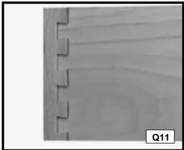
Once you achieve the correct depth, secure the router bit depth guide in place with a 3/8" wrench. If the drawer front overlaps the drawer side, reposition the template toward you (Fig. Q11).
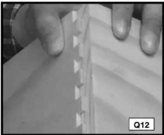
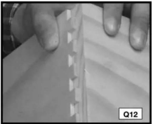
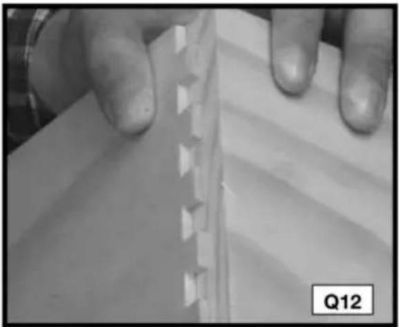
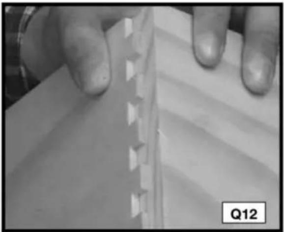
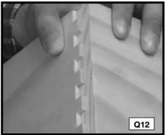
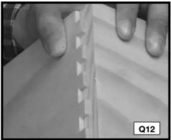
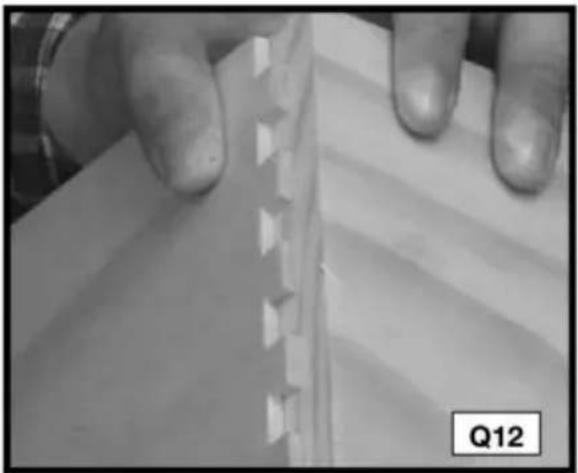
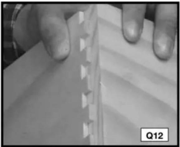
If the drawer front is recessed from the edge of the drawer side (Fig. Q12), reposition the template away from you.
RABBETED HALF-BLIND DOVETAILS
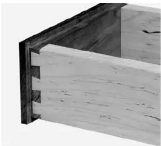
To produce rabbeted half-blind dovetails (drawer front), cut the pins for a half-blind joint after the drawer front has been rabbeted. The depth of the rabbet must be deeper than the half-blind router bit depth guide.
NOTE: Cut the tails first.
For miniature half-blinds, use the 28104-3 accessory kit.
Use scrap wood until you are comfortable with the jig.
ITEMS NEEDED
• Half-blind Dovetail Template • 1/4" x 15.4 x 13 Dovetail Bit • 3/4" O.D. Template Guide, - Template Guide Lock Nut,
CUTTING THE TAILS
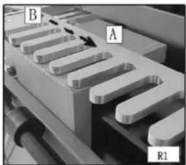
Step 1 - Clamp a scrap board (A) Fig. R1 in the upper clamp (horizontal mounting position). Use scrap board that is thick enough to prevent the bit from contacting the base (1/2" will work). Secure the template (B) on top of the scrap board (Fig. R1). Ensure the flatness by holding one hand on the board and using the other to tighten the template knobs.
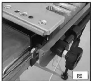
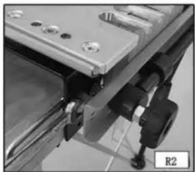
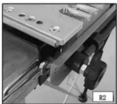
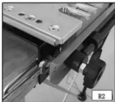
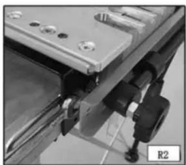
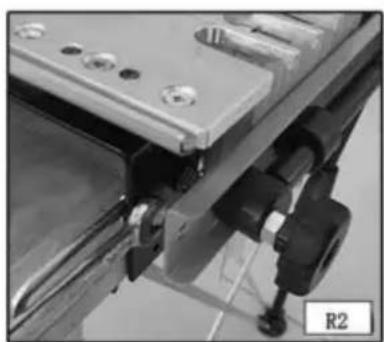
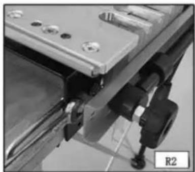
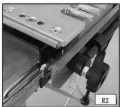
Step 2 - Move the left offset guide all the way to the left (Fig. R2).
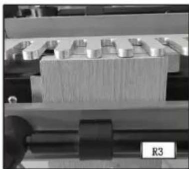
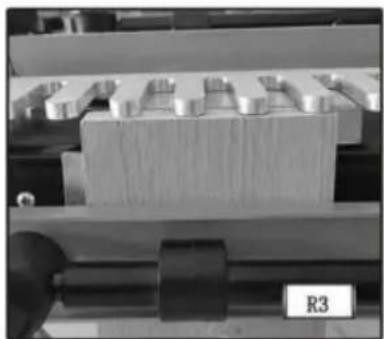
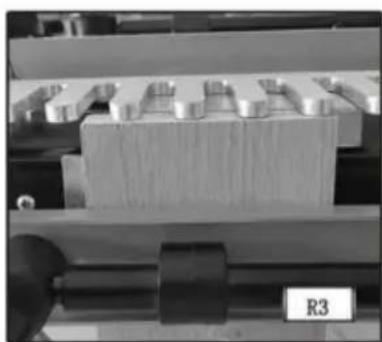
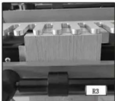
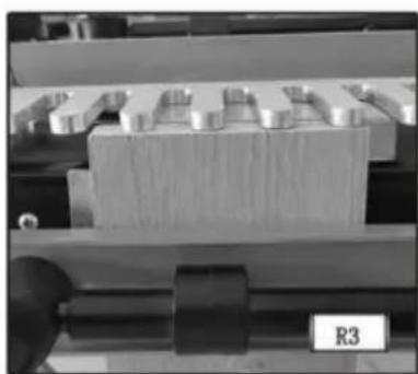
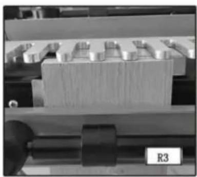
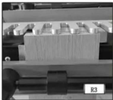
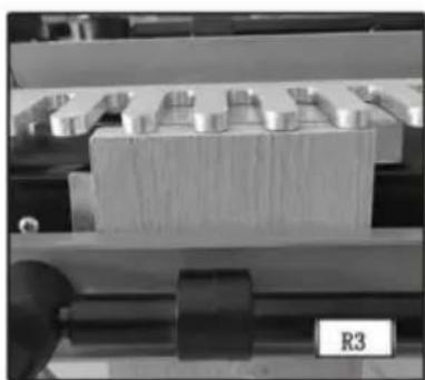
Step 3 - Position and clamp the tail board in the lower clamp (vertical mounting position) with the outside surface against the jig base (Fig. R3).
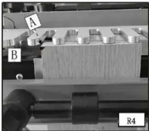
Step 4 - Make a spacer equal to the rabbit's width. Put the spacer (A) Fig. R4 against the left edge of the tail board, move the left offset guide (B) flush against the spacer, and secure the offset guide.
Step 5 - Reposition the scrap board (C) so that it is flush with the offset guide and the back edge of the vertical board.
Step 6 - Align the "half-blind" template line (A) Fig. R5 with the line formed where the scrap board (B) and the vertical board (C) meet.
Step 7 - Mount the dovetail bit and template guide to the router and set the router bit depth using the "half-blind" bit depth guide (Fig. R6).
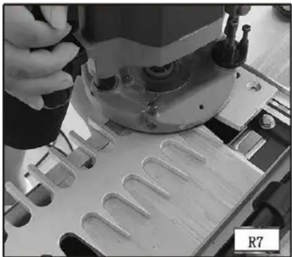
Step 8 - Make a climb-cut from right to left across the outer edge of the tail board to reduce tear-out (Fig. R7).
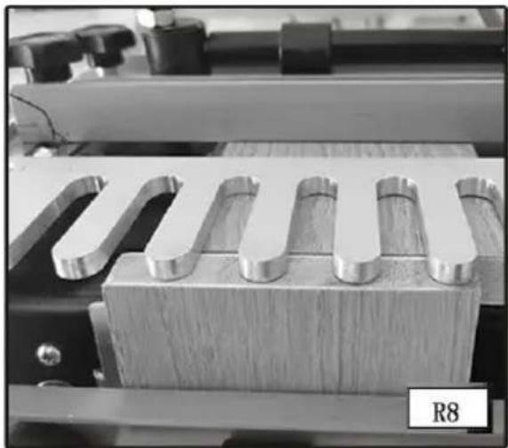
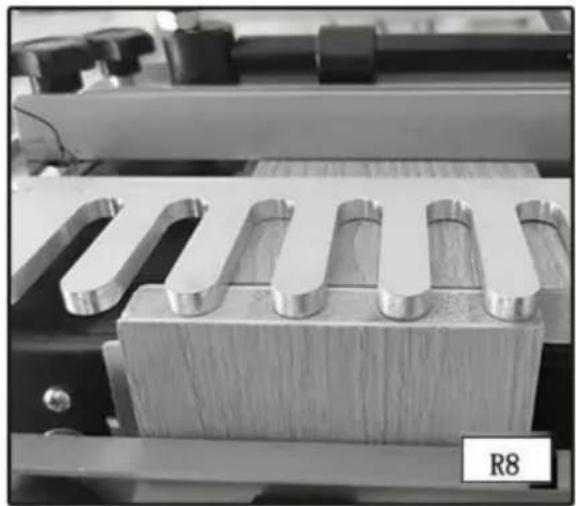
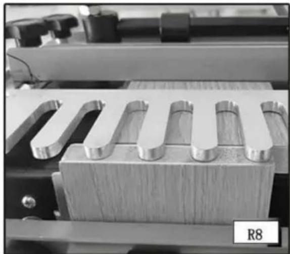
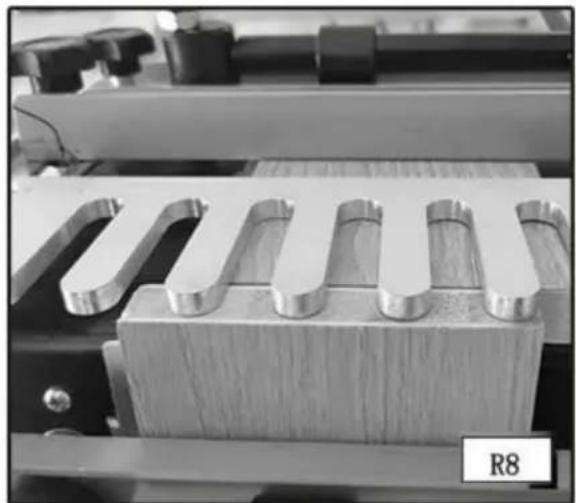
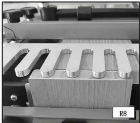
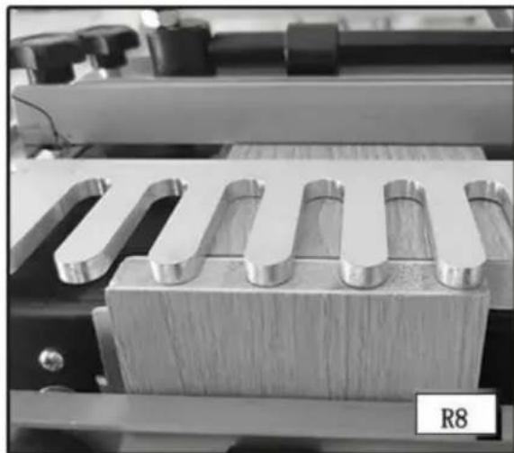
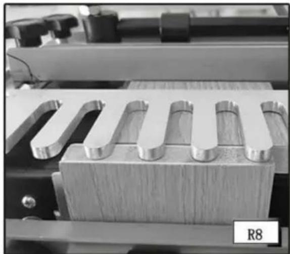
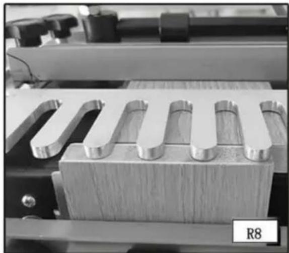
Step 9 - Rout in and out of the fingers of the template from left to right (Fig. R8). Remove the boards.
CUTTING THE PINS
Step 1 - Clamp the pin board in the upper clamp (horizontal mounting position) with the outside surface against the jig's base.
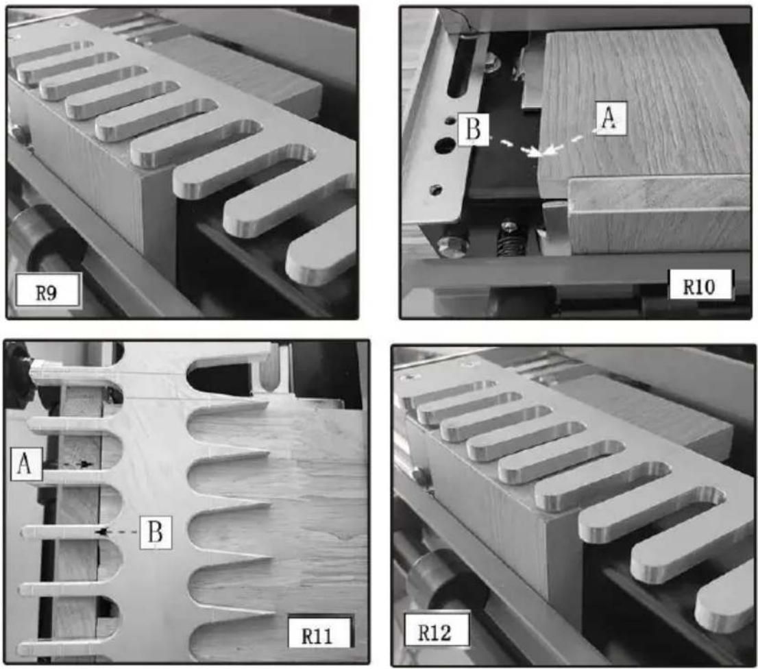
Step 2 - Secure the template on top of the pin board, making sure that it is flat (Fig. R9).
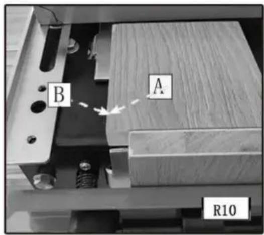
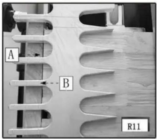
Step 3 - Reposition the pin board (A) Fig. R10 so that it is flush to the left offset guide (B) and the inside edge of the rabbit (A) Fig. R11 is aligned with the "half-blind" alignment line (B). Lower the router bit on the depth guide and lock the position on your router.
Step 4 - Rout in and out of the fingers of the template from left to right.
Step 5 - Remove the boards from the jig and test for fit.
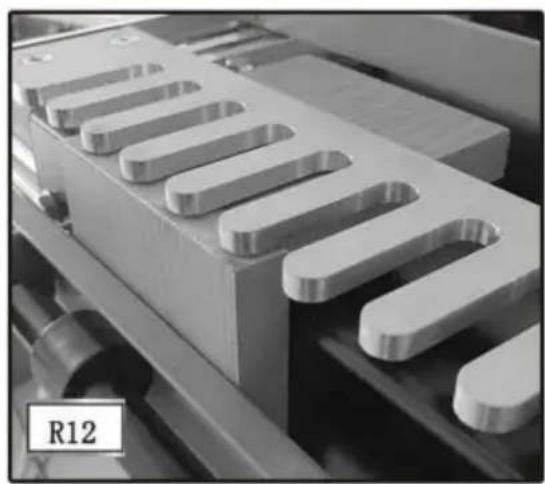
NOTE: Alternate method for aligning the pin board - Use a board with a rabbit the same width as the rabbit on the workpiece (R12).
FITTING AND TROUBLESHOOTING
Fitting and troubleshooting methods for the lipped front half-blind dovetail are the same as for the regular half-blind dovetail.
BOX JOINTS
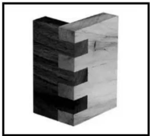
Box joints have straight protrusions that interlock and must be held together by glue. The large amount of gluing surface provides the strength necessary for large projects.
NOTE: If you are using the 28104 dovetail jig, you will need the 28104 accessory kit to cut this joint. You will need the 28104-3 accessory kit for the miniature box joints.
Box joint fingers are spaced in 1" increments (1/2" for miniature).
ITEMS NEEDED
• Through Dovetail and Box Joint Template • 1/2" x 15.4° x 13° Dovetail Bit • 3/4" O.D. Template Guide, • Template Guide Lock Nut,
CUTTING THE FIRST WORKPIECE
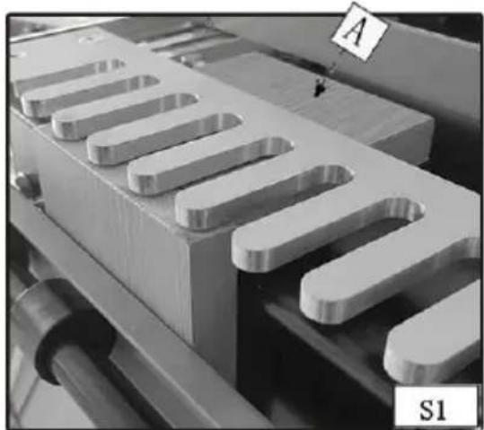
Step 1 - Clamp a scrap board (A) Fig. S1 in the upper clamp (horizontal mounting position) that is the same thickness as the second workpiece.
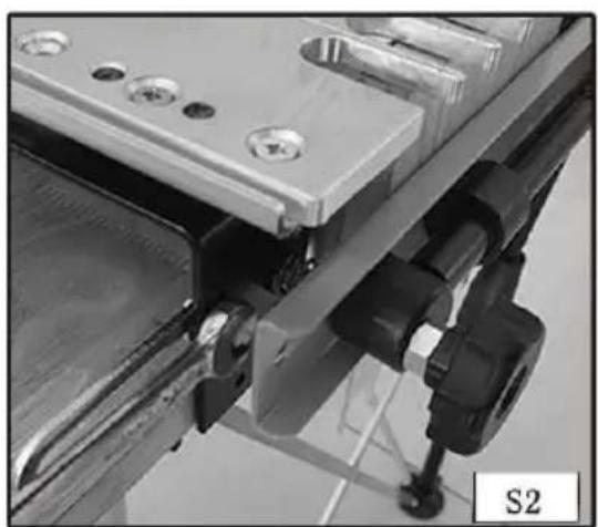
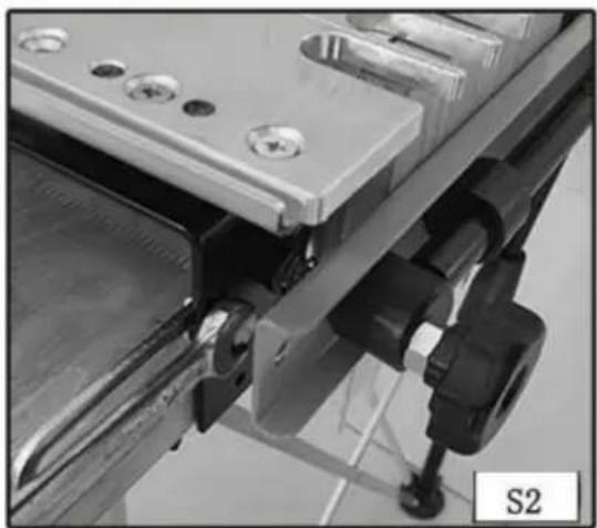
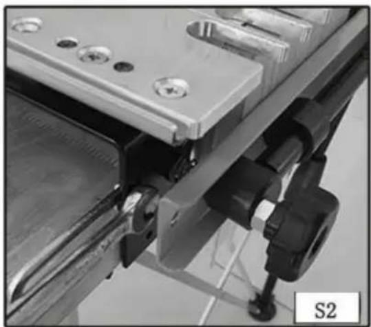
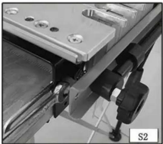
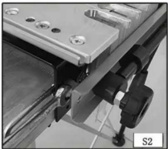
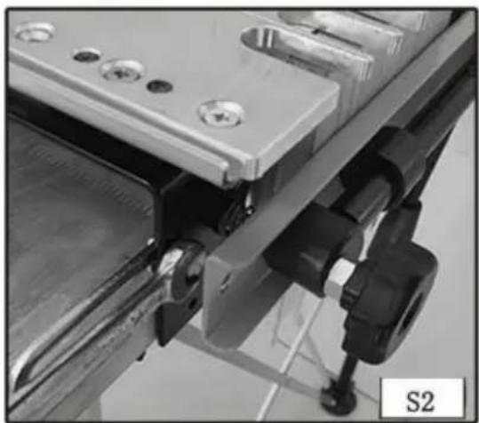
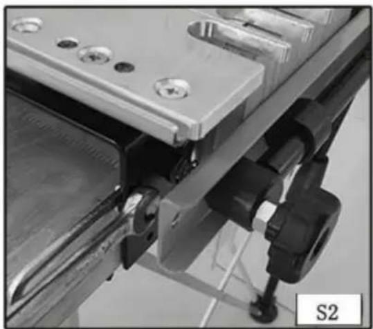
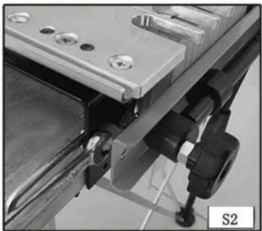
Step 2 - Use the wrench (A) Fig. S2 to loosen the screw on the left offset guide (B). Move the guide to the far left.
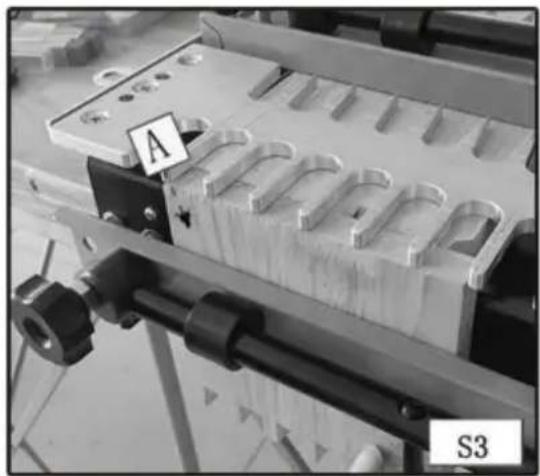
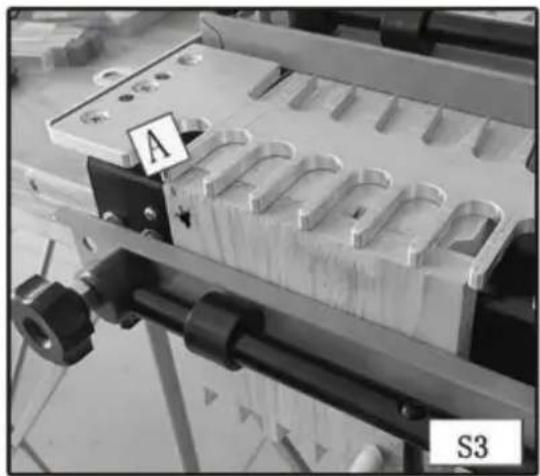
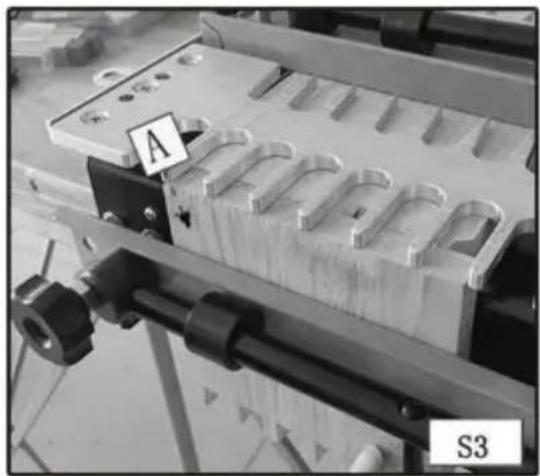
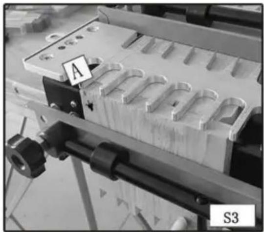
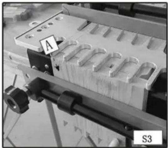
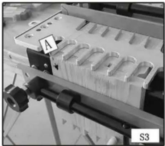
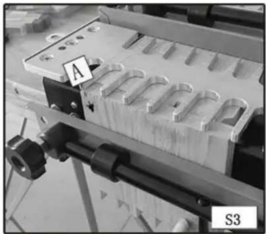
Step 3 - Mount the workpiece (A) Fig. S3 in the lower clamp (vertical mounting position) with the outside surface against the jig base.
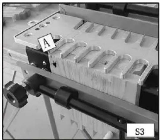
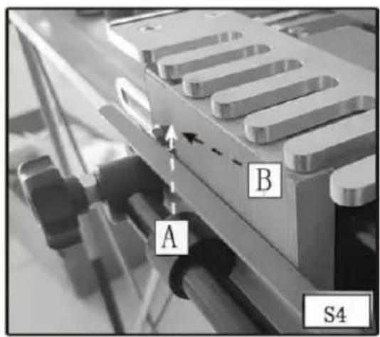
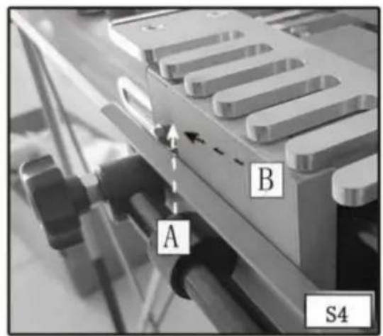
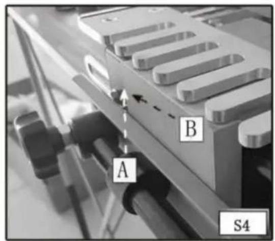
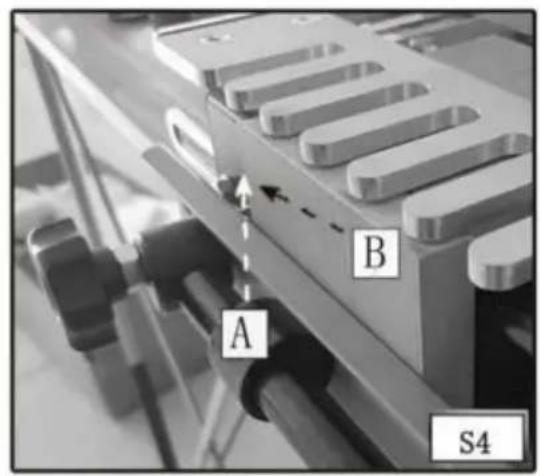
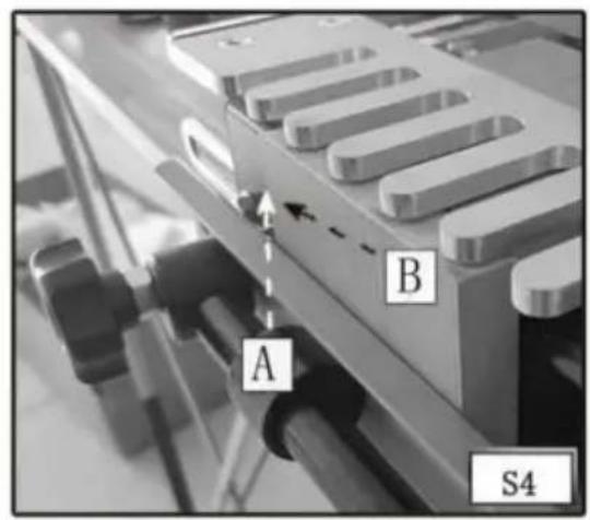
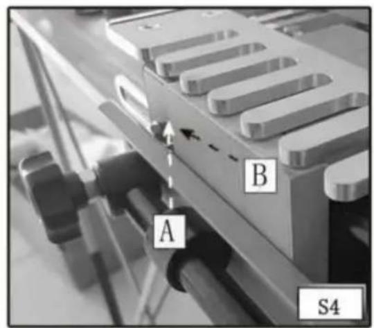
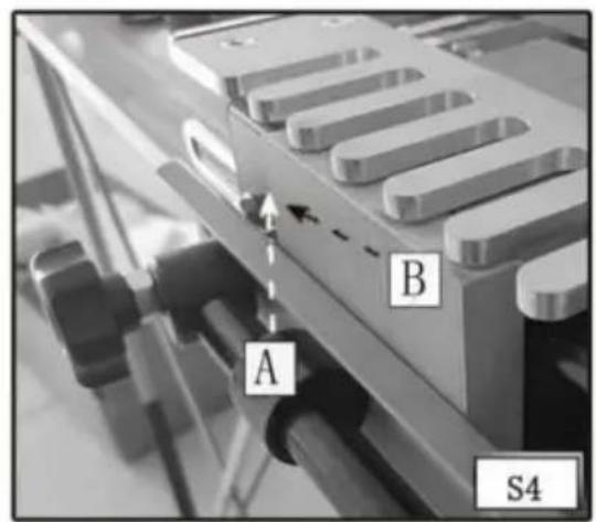
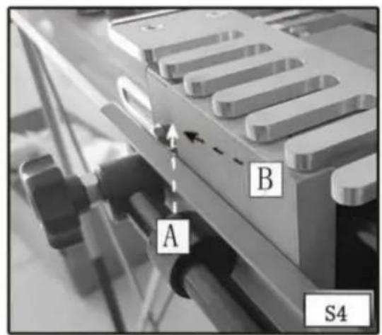
Step 4 - Reposition the left offset guide (A) Fig. S4 flush against the workpiece (B).
Step 5 - Align the template, using the "tails/Box" template line with the line formed where the scrap board and the workpiece meet.
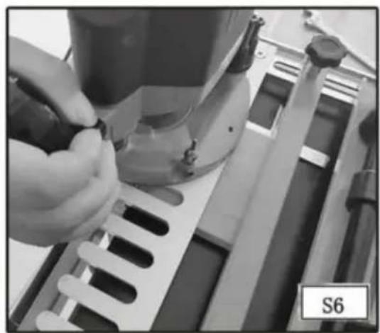
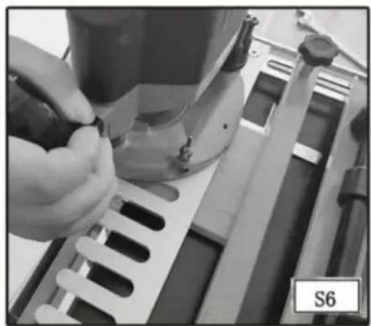
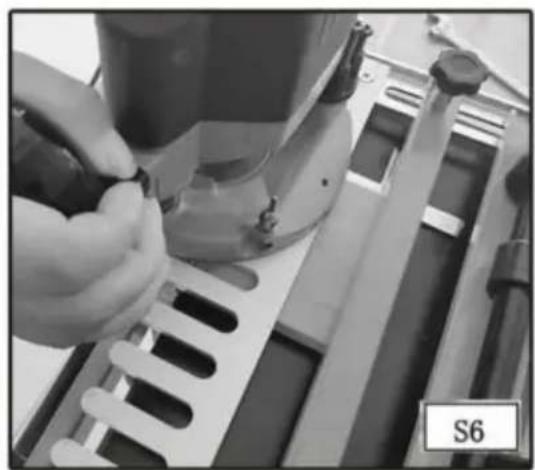
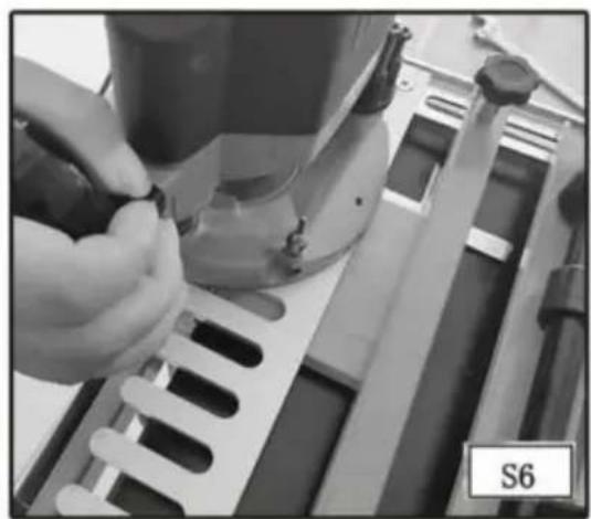
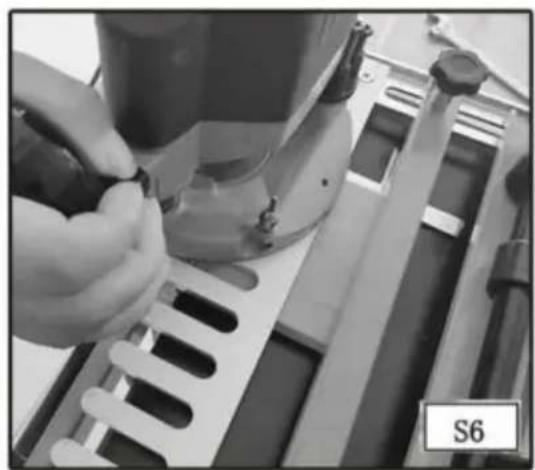
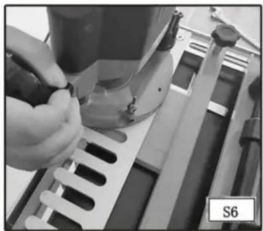
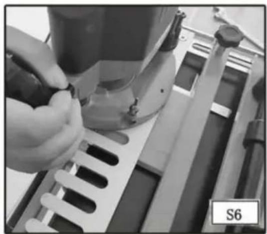
Step 6 - Mount the straight bit and template guide on the router and set the router bit depth using the "tails/box" bit depth guide.
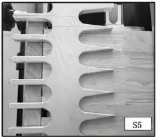
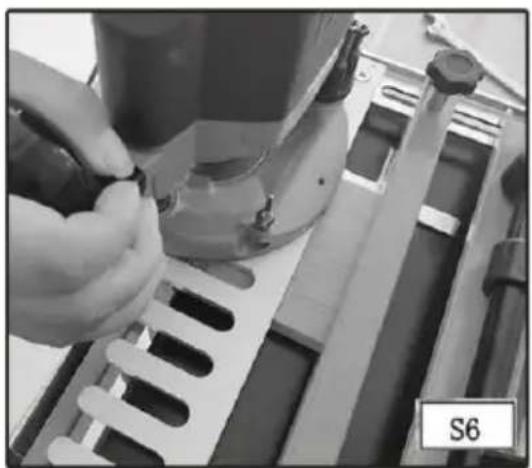
Step 7 - Rout between the fingers of the jig with the template guide against the left side of the fingers, both in and out. This light pressure toward the left will help to prevent loose joints.
Step 8 - Remove the workpiece from the jig.
CUTTING THE SECOND WORKPIECE
NOTE: If the thickness is different between the first and second workpiece, replace the scrap piece in the upper clamp (horizontal mounting position) with another that is the same thickness as the first workpiece.
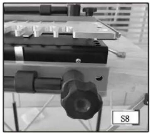
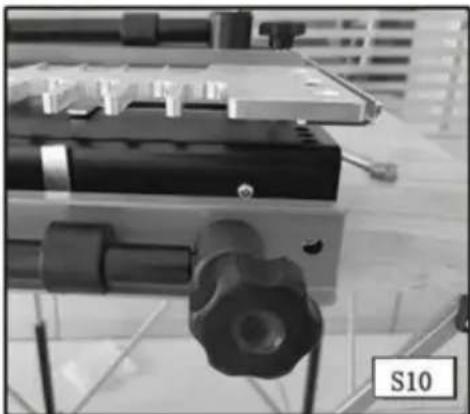
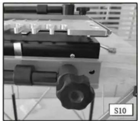
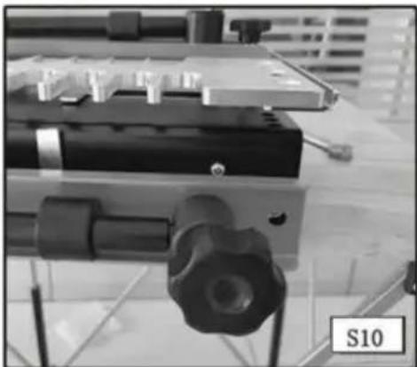
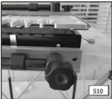
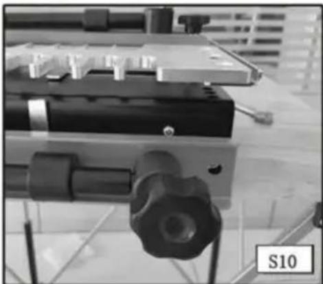
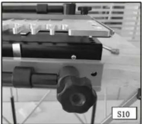
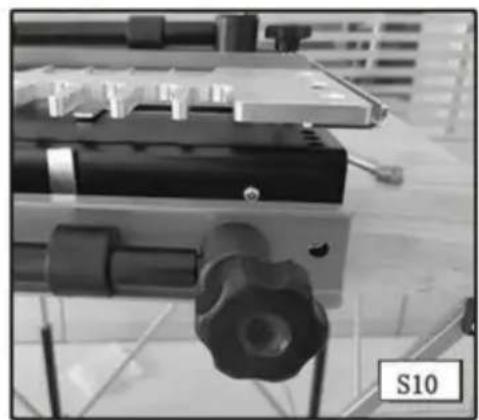
Step 1 - Use the wrench (A) Fig. S8 to loosen the screw on the right offset guide (B) Fig. S10. Move the guide to the far right.
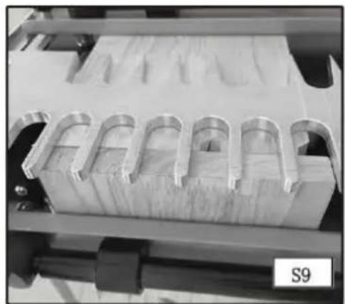
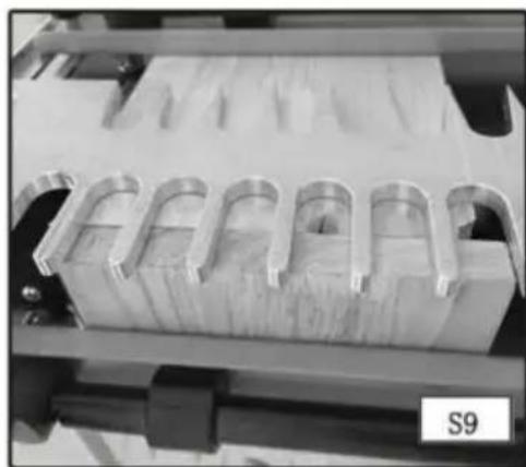
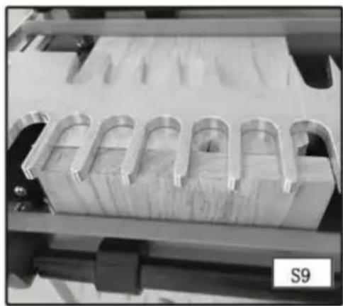
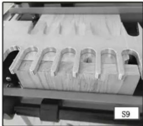
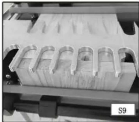
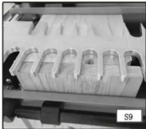
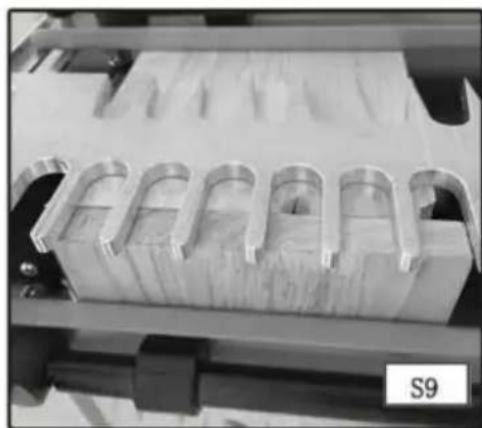
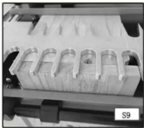
Step 2 - Clamp the first board in the lower clamp on the right side of the jig with the fingers protruding past the template (Fig. S9). Center the protrusions of the wood in between the fingers of the template.
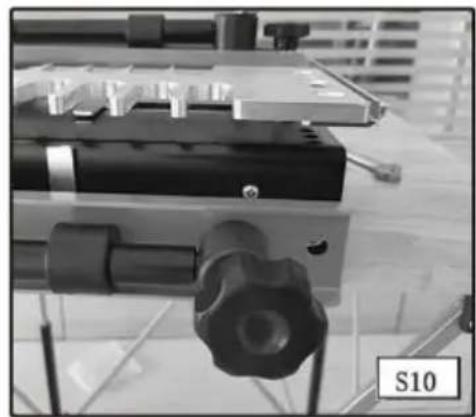
Step 3 - Move the right offset guide flush against the workpiece and secure it with the wrench (Fig. S10).
Step 4 - Remove the first workpiece.
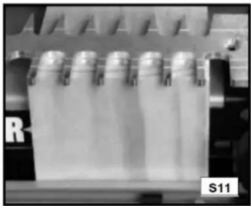
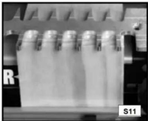
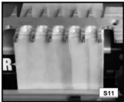
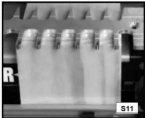
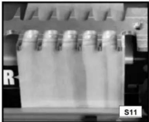
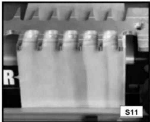
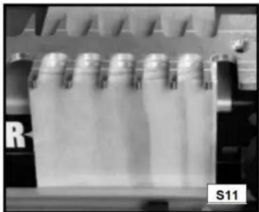
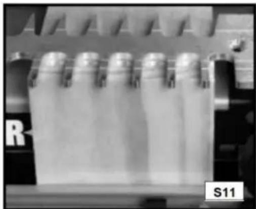
Step 5 - Clamp the second workpiece (A) Fig. S11 in the lower clamp (vertical mounting position) on the right side of the jig flush against both the template (B) and against the right offset guide (C) with the outside surface facing away from the jig.
Step 6 - If the first and second workpieces are of different thicknesses, reset the router bit depth using the "tails/box" bit depth guide.
Step 7 - Rout between the fingers of the jig with the templet guide against the left side of the fingers, both in and out. This light pressure toward the left will help to prevent loose joints (Fig. S12).
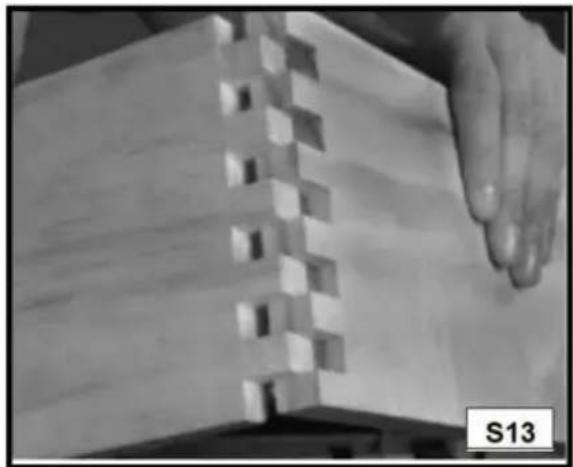
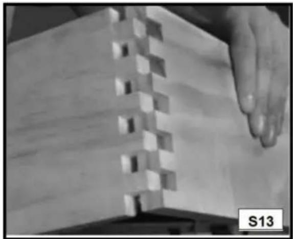
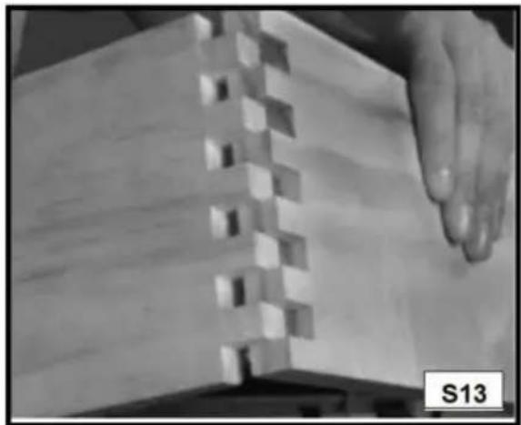
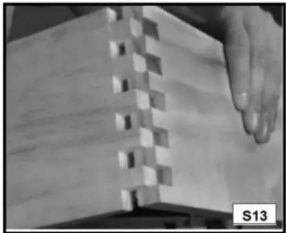
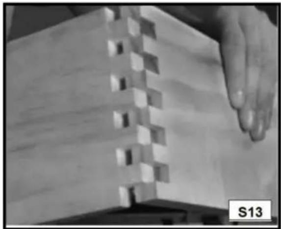
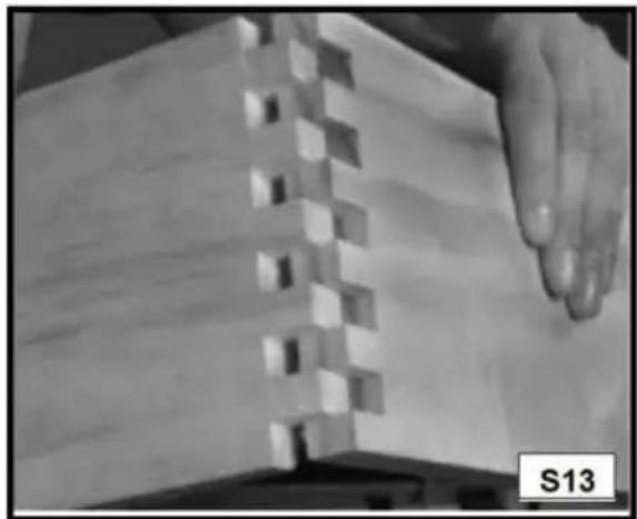
Step 8 - Remove the second workpiece and assemble the joint (Fig. S13).
NOTE: The fit (tightness) of the box joint cannot be adjusted.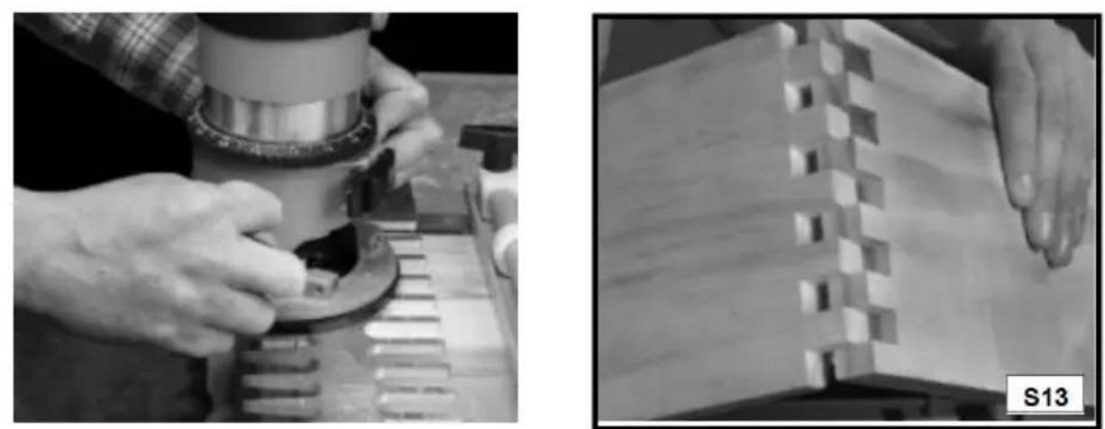
SLIDING DOVETAILS
Sliding dovetails are used primarily in the construction of cabinets, entertainment centers and shelving. The 28104 series jigs have three preset depths for dadoes (1/4", 3/8" and 1/2"), but you can manually set your router bit depth to any setting.
NOTE: Be certain that the router bit will not cut into the base or offset guides during this cut. Everything is provided for this cut in 28104-3 jigs.
Manufacturer: Shanghaimuxinmuyeyouxiangongsi
Address: Shuangchenglu 803nong11hao1602A-1609shi, baoshanqu, shanghai 200000 CN.
EC REP: E-CrossStu GmbH.
Mainzer Landstr.69, 60329 Frankfurt am Main.
UK REP: YH CONSULTING LIMITED.
C/O YH Consulting Limited Office 147, Centurion House, London Road, Staines-upon-Thames, Surrey, TW18 4AX
Imported to AUS: SIHAO PTY LTD.
1 ROKEVA STREETEASTWOOD NSW 2122 Australia
Imported to USA: Sanven Technology Ltd.
Suite 250, 9166 Anaheim Place, Rancho Cucamonga, CA 91730
Please view the installation video of the product

VEVOR®
TOUGH TOOLS, HALF PRICE
Technical Support and E-Warranty Certificate
www.vevor.com/support
VEVOR®
TOUGH TOOLS, HALF PRICE
VEVOR®
TOUGH TOOLS, HALF PRICE
NEED HELP? CONTACT US!
BOX JOINT (FINGER)
PRODUCT CAPACITIES
CARTON CONTENTS
DOVETAIL TEMPLATES
28104-1
28104-3
OPERATION
MODEL ASSEMBLY
MODEL LOADING
Supported
Not supported
WOOD POSITIONING

MODEL GUIDES
WOOD PREPARATION
REQUIRED ITEMS
FOR DOVETAIL REPAIR
REQUIRED ITEMS
INSTALLATION AND REPAIR
CUTTING THE TAILS
CUT THE PINS
CUTTING THE FIRST PIECE
C/O YH Consulting Limited, Office 147, Centurion House, London Road, Staines-upon-Thames, Surrey, TW18 4AX
Imported in Australia: SIHAO PTY LTD.
1 ROKEVA STREET, ASTWOOD NSW 2122, Australia
Office 250, 9166 Anaheim Place, Rancho Cucamonga, CA 91730
VEVOR®
TOUGH TOOLS, HALF PRICE
www.vevor.com/support
VEVOR®
TOUGH TOOLS, HALF PRICE
VEVOR®
TOUGH TOOLS, HALF PRICE
HALF-BLIND DOVETAILS WITH RABBET
FINGER JOINT
PRODUCT FEATURES
BOX CONTENTS
OPERATION
MOUNTING THE TEMPLATES
Supported
Not supported
TEMPLATE MANUALS
WOOD PREPARATION
ASSEMBLY AND TROUBLESHOOTING
HALF-BLIND DOVETAILS WITH RABBET
C/O YH Consulting Limited Office 147, Centurion House, London
Street, Staines-upon-Thames, Surrey, TW18 4AX
Suite 250, 9166 Anaheim Place, Rancho Cucamonga, CA 91730
VEVOR®
TOUGH TOOLS, HALF PRICE
www.vevor.com/support
VEVOR®
TOUGH TOOLS, HALF PRICE
VEVOR®
TOUGH TOOLS, HALF PRICE
NEED HELP? CONTACT US!
BOX JOINT (FINGER).
PRODUCT CAPACITY
OPERATION
TEMPLATE MOUNTING
MODEL SUPPORT
Supported
Not supported
MODEL GUIDES
Standard through dovetail …… Tail board range …… From 1/4" to 1" Pin board range …… From 1/4" to 3/4"
From 1/2" to 1-1/8" Dovetail joints
REQUIRED ITEMS
THROUGH DOVETAIL TROUBLESHOOTING
REQUIRED ITEMS
CUTTING THE TAILS
CUTTING THE PINS
CUTTING THE FIRST PIECE

C/O YH Consulting Limited Office 147, Centurion House, London Street, Staines-upon-Thames, Surrey, TW18 4AX
Imported in AUS: SIHAO PTY LTD.
1 ROKEVA STREETEASTWOOD NSW 2122 Australia
Suite 250, 9166 Anaheim Place, Rancho Cucamonga, CA 91730
VEVOR®
TOUGH TOOLS, HALF PRICE
www.vevor.com/support
VEVOR®
TOUGH TOOLS, HALF PRICE
VEVOR®
TOUGH TOOLS, HALF PRICE
Dovetail Template
MODEL: 28104-1 28104-3
BOX JOINT (FINGER)
PRODUCT CAPACITIES

BOX CONTENTS
OPERATION
TEMPLATE ASSEMBLY
Supported
Not supported

TEMPLATE GUIDES
Standard through dovetail …… Back board range …… 1/4" to 1" Peg board range …… 1/4" to 3/4"
CUTTING THE TAILS
CUT THE PINS
CUTTING THE FIRST WORKPIECE
Suite 250, 9166 Anaheim Place, Rancho Cucamonga, CA 91730
VEVOR®
TOUGH TOOLS, HALF PRICE
www.vevor.com/support
VEVOR®
TOUGH TOOLS, HALF PRICE
VEVOR®
TOUGH TOOLS, HALF PRICE
NEED HELP? CONTACT US!
HALF-BLIND DOVETAIL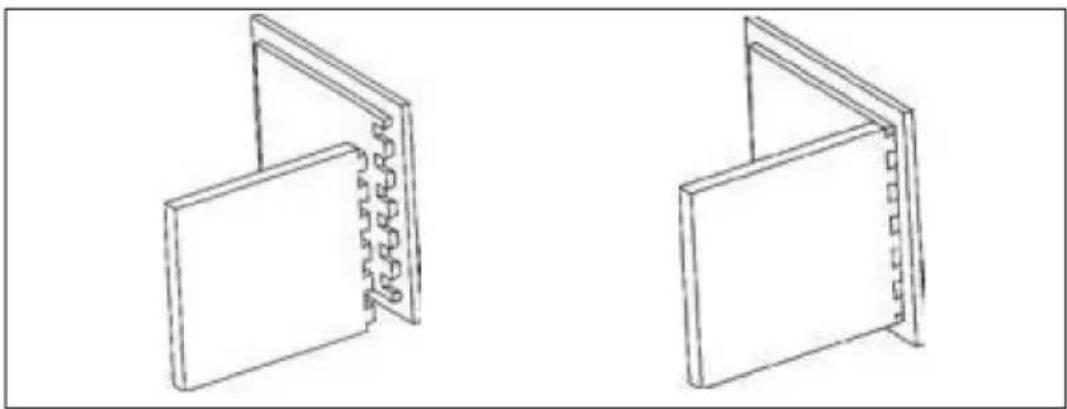
BOX JOINT (FINGER JOINT).
PRODUCT FEATURES
CARTON CONTENTS
DOVETAIL JIGS
28104-1
28104-3
OPERATION
TEMPLATE MOUNTING
TEMPLATE SUPPORT
Supported
Unsupported
WOOD LAYOUT
IRRITATION REDUCTION
TEMPLATE GUIDES
WOOD PREPARATION
REQUIRED ITEMS
THROUGH DOVETAIL TROUBLESHOOTING
REQUIRED ITEMS
ASSEMBLY AND TROUBLESHOOTING
HALF-BLIND DOVETAIL
TAIL CUTS
PIN CUTS
CUTTING THE FIRST WORKPIECE
C/O YH Consulting Limited Office 147, Centurion House, London
Road, Staines-upon-Thames, Surrey, TW18 4AX
Import to AUS: SIHAO PTY LTD.
1 ROKEVA STREET EASTWOOD NSW 2122 Australia
Import to USA: Sanven Technology Ltd.
Apartment 250, 9166 Anaheim Place, Rancho Cucamonga, California 91730
VEVOR®
TOUGH TOOLS, HALF PRICE
www.vevor.com/support
VEVOR®
TOUGH TOOLS, HALF PRICE
Technical support and e-warranty certificate www.vevor.com/support
Dovetail jig
MODEL: 28104-1 28104-3
VEVOR®
TOUGH TOOLS, HALF PRICE
Dovetail jig
MODEL: 28104-1 28104-3
NEED HELP? CONTACT US!
PRODUCT FEATURES
BOX CONTENTS
Dovetail jigs
28104-1
28104-3
OPERATION
TEMPLATE ASSEMBLY
Supported
Not supported
PLACING THE WOOD

TEAROUT REDUCTION
TEMPLATE GUIDE
WOOD PREPARATION
ITEMS NEEDED
ITEMS NEEDED
ASSEMBLY AND TROUBLESHOOTING
CUTTING THE TENONS
CUTTING THE FIRST WORKPIECE
C/O YH Consulting Limited Office 147, Centurion House, Londen Road, Staines-upon-Thames, Surrey, TW18 4AX
Suite 250, 9166 Anaheim Place, Rancho Cucamonga, CA 91730
VEVOR®
TOUGH TOOLS, HALF PRICE
Technical support and e-warranty certificate www.vevor.com/support
VEVOR®
TOUGH TOOLS, HALF PRICE
VEVOR®
TOUGH TOOLS, HALF PRICE
Dovetail Jig
MODEL: 28104-1 28104-3
NEED HELP? CONTACT US!
RABBET HALF-BLIND DOVETAILS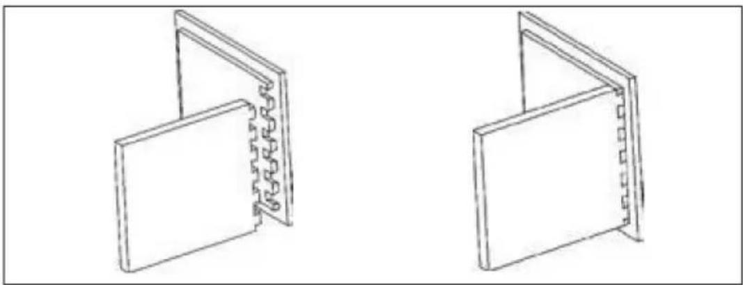
BOX (FINGER) JOINT
PRODUCT CAPACITIES
CARTON CONTENTS
DOVETAIL JIGS
28104-1
28104-3

DRIFT
MALLMONTERING
MALLSTÖD
Stöds
Utan stöd
POSITIONERING AV TRÄET
REDUKTION AV RIVNING

MALLGUIDE
TRÄBEREDNING
Standard through dovetails …… Tail Board Range …… 1/4" to 1"
Pin Board Range ...... 1/4" to 3/4"
ARTICLES NEEDED
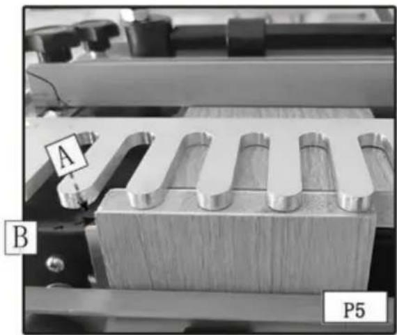
Step 5 - Space between the template fingers (Fig. P12).
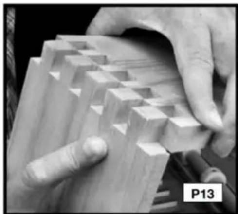
THROUGH DOVETAIL TROUBLESHOOTING
ARTICLES NEEDED
• Half-blind dovetail template • 1/4*15.4*13 dovetail bits •
3/4" OD template guide,
CUTTING HALF-BLIND DOVETAILS
ASSEMBLY AND TROUBLESHOOTING
RABBET HALF-BLIND DOVETAILS
CUTTING TAILS
ASSEMBLY AND TROUBLESHOOTING
CUTTING THE FIRST WORKPIECE
UK REP: YH CONSULTING LIMITED.
C/O YH Consulting Limited Office 147, Centurion House, London Road, Staines-upon-Thames, Surrey, TW18 4AX
Imported to AUS: SIHAO PTY LTD.
1 ROKEVA STREET EASTWOOD NSW 2122 Australia
Imported to USA: Sanven Technology Ltd.
Suite 250, 9166 Anaheim Place, Rancho Cucamonga, CA 91730
VEVOR®
TOUGH TOOLS, HALF PRICE
www.vevor.com/support
- DOVETAIL JIG
- VEVOR®
- NEED HELP? CONTACT US
- SAFETY GUIDELINES - DEFINITIONS
- DANGER
- WARNING
- CAUTION
- IMPORTANT SAFETY INSTRUCTIONS
- SAVE THESE INSTRUCTIONS
- ADDITIONAL SAFETY RULES
- FAILURE TO FOLLOW THESE RULES MAY RESULT IN SERIOUS PERSONAL INJURY
- REPLACEMENT PARTS
- BOX (FINGER) JOINT
- PRODUCT CAPABILITIES
- JIGS
- JIG OVERVIEW
- CARTON CONTENTS
- DOVETAIL JIGS
- ACCESSORY
- ADDITIONAL TOOLS REQUIRED
- MOUNTING INSTRUCTIONS
- OPERATION
- CLAMPS
- TEMPLATE MOUNTING
- TEMPLATE SUPPORT
- POSITIONING THE WOOD
- HALF-PINS VS. HALF-TAILS
- TEAROUT REDUCTION
- ALIGNING THE TEMPLATES
- TEMPLATE GUIDES
- WOOD PREPARATION
- BOARD THICKNESS
- BOARD LENGTHS
- PROJECT LAYOUT
- DRAWERS
- TIPS FOR MAKING DRAWERS
- BASIC JOINTS
- THROUGH DOVETAILS
- ITEMS NEEDED
- CUTTING THE TAILS
- CUTTING THE PINS
- THROUGH DOVETAIL TROUBLESHOOTING
- HALF-BLIND DOVETAILS
- CUTTING HALF-BLIND DOVETAILS
- FITTING AND TROUBLESHOOTING
- RABBETED HALF-BLIND DOVETAILS
- BOX JOINTS
- CUTTING THE FIRST WORKPIECE
- CUTTING THE SECOND WORKPIECE
- SLIDING DOVETAILS
- TOUGH TOOLS, HALF PRICE
- BOX JOINT (FINGER)
- PRODUCT CAPACITIES
- MODEL ASSEMBLY
- MODEL LOADING
- WOOD POSITIONING
- MODEL GUIDES
- REQUIRED ITEMS
- FOR DOVETAIL REPAIR
- INSTALLATION AND REPAIR
- CUT THE PINS
- CUTTING THE FIRST PIECE
- HALF-BLIND DOVETAILS WITH RABBET
- FINGER JOINT
- PRODUCT FEATURES
- BOX CONTENTS
- MOUNTING THE TEMPLATES
- TEMPLATE MANUALS
- ASSEMBLY AND TROUBLESHOOTING
- PRODUCT CAPACITY
- MODEL SUPPORT
- TEMPLATE ASSEMBLY
- WOOD LAYOUT
- IRRITATION REDUCTION
- HALF-BLIND DOVETAIL
- TAIL CUTS
- PIN CUTS
- PLACING THE WOOD
- TEMPLATE GUIDE
- CUTTING THE TENONS
- DRIFT
- MALLMONTERING
- MALLSTÖD
- POSITIONERING AV TRÄET
- REDUKTION AV RIVNING
- MALLGUIDE
- TRÄBEREDNING
- ARTICLES NEEDED
- RABBET HALF-BLIND DOVETAILS
- CUTTING TAILS
Brand : Vevor
Model : 28104-3
Category : Carpentry template