
DR20UHF-HH - Microphone IBIZA SOUND - Free user manual and instructions
Find the device manual for free DR20UHF-HH IBIZA SOUND in PDF.

| Brand | Ibiza Sound |
| Model | DR20UHF-HH |
| Product type | UHF microphone system with receiver and two handheld microphones |
| Frequencies | UHF 863.9 & 864.9 MHz |
| Range | 10 to 60 m |
| Receiver power supply | 12 V= 1 A via mains adapter (100-240 V~ 50/60 Hz) |
| Microphone power supply | 2 AA (LR6) batteries, 1.5 V each |
| Battery life | 6 to 8 hours |
| Weight | 1.05 kg (DR20UHF-HH) |
| Audio output connectors | Balanced XLR, unbalanced 6.35 mm jack |
| Max. output level | Balanced: 0-400 mV; Unbalanced: 0-200 mV |
| AF output impedance | 2.2 kOhms |
| Bandwidth | 40 Hz - 18 kHz |
| Signal-to-noise ratio | >105 dB |
| Total harmonic distortion | <0.5% at 1 kHz |
| Sensitivity | -105 dB |
| Main features | Dual UHF receiver with volume control, LCD display, external antenna; handheld microphones with on/off switch and low battery indication |
| Care and cleaning | Clean with a soft, dry cloth. Keep away from moisture and dust. Do not use solvents or abrasive products. |
| Safety | Do not expose to rain or moisture. Disconnect adapter during prolonged non-use. Keep away from flames and extreme temperatures (<5°C / >35°C). Batteries: do not incinerate, keep out of reach of children. |
| Spare parts and repairability | No user-serviceable parts. For any repair, contact an authorized service center. Batteries are replaceable by the user. |
| General information | Indoor use only. Compliant with RED directive 2014/53/EU. Check local restrictions on UHF band usage. |
Frequently Asked Questions - DR20UHF-HH IBIZA SOUND
User questions about DR20UHF-HH IBIZA SOUND
0 question about this device. Answer the ones you know or ask your own.
Ask a new question about this device
Download the instructions for your Microphone in PDF format for free! Find your manual DR20UHF-HH - IBIZA SOUND and take your electronic device back in hand. On this page are published all the documents necessary for the use of your device. DR20UHF-HH by IBIZA SOUND.
USER MANUAL DR20UHF-HH IBIZA SOUND
natural_image
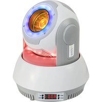
Black Ibiza ultrasonic audio device with external microphone and I2O3 interband (no visible text or symbols)MANUAL
WITH HANDHELD, HEADSET, TIE-CLIP MIC & BELT-CLIP TRANSMITTER
OPERATING INSTRUCTIONS
Congratulations to the purchase of your new UHF microphone system.
This manual covers following items:
DR20UHF-HH: UHF receiver with 2 handheld UHF microphones
DR20UHF-HB: UHF receiver with 1 handheld and 1 tie-clip mic with belt-clip transmitter
HM20-UHF: UHF handheld microphone
HS20-UHFA/HS20-UHFB: UHF belt-clip transmitter with headset & tie-clip mic
EXPLANATION OF SIGNS
CE Accordance with the requirements of CE standard

The product is for indoor use only

This marking indicates that this product should not be disposed with other household wastes throughout the EU. To prevent possible harm to the environment or human health from uncontrolled waste disposal, recycle it responsibly to promote the sustainable reuse of material resources. To return your used device, please use the return and collection systems or contact the retailer where the product was purchased. They can take this product for environmental safe recycling.
RESTRICTIONS ON USE
This product complies with European standards and RED 2014/53 / EU directive. It uses a UHF frequency band harmonized at European level. The user should check with the regulatory body in his country whether this frequency band is allowed without restriction.
IMPORTANT SAFETY INSTRUCTIONS AND DANGER WARNINGS
- Please read the manual carefully and keep it for future reference.
- The unit shall be connected to a power supply only of the type described.
• To reduce the risk of fire or electrical shock, do not expose this unit to rain or moisture. - Unplug the unit from the wall socket when it is not to be used for a long period of time.
- Adequate care shall be taken so that foreign objects do not fall, or liquids are not spilled into the enclosure through openings.
- Do not remove the cover or back, as there are no user-serviceable parts inside.
- The apparatus shall not be exposed to dripping or splashing and that no objects filled with liquids, such as vases, shall be placed on the apparatus.
- Do not place on the apparatus as naked flame source, such as lighted candles.
- Do not use the unit in a tropical climate. Only for use in temperate climates.
- Unauthorized conversions and/or modifications of the appliance are not permitted for safety and licensing reasons (CE).
- The appliance may not be exposed to extreme temperatures ( < +5^ / > +35^ ) in operation.
- The appliance may not be subject to strong vibrations or heavy mechanical strain.
- DISCONNECT DEVICE: Where the MAINS plug or an appliance coupler is used as the disconnect device, the disconnect device shall remain readily operable.
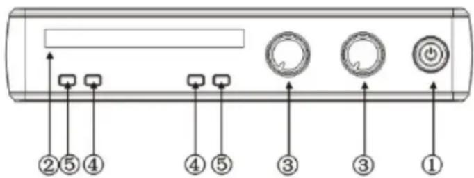
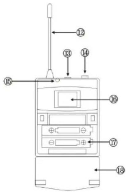
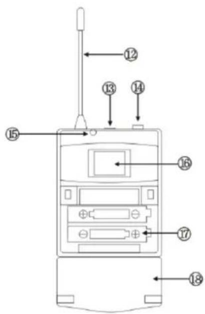
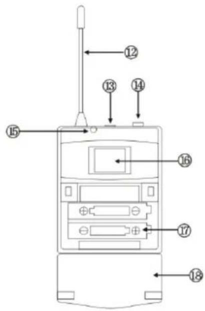
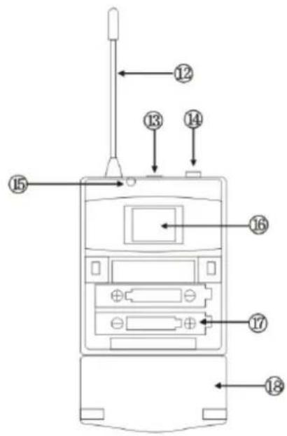
RECEIVER FRONT PANEL
- Power switch: To turn the unit on and off
- Display: shows information such as signal, frequency, AF, RF, etc.
- Volume control
- AF
- RF
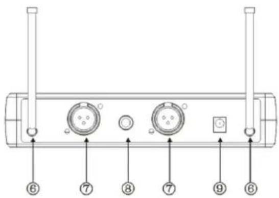
RECEIVER REAR PANEL
- Antenna
- Balanced audio output
- Mix out
- 12V== input jack
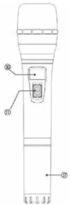
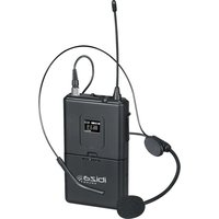
TRANSMITTERS
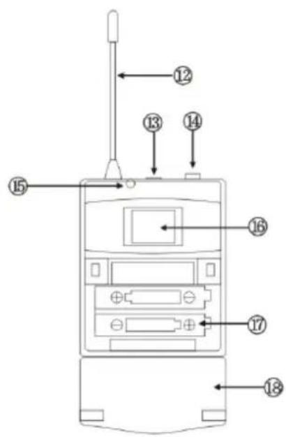
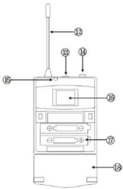
HANDHELD MICROPHONE
- LCD display
- Power switch
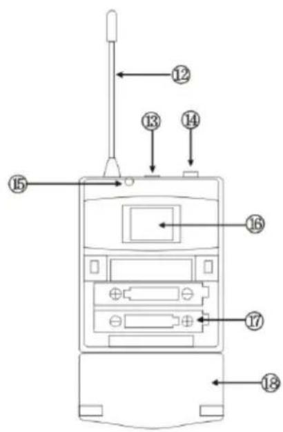
BELT-CLIP TRANSMITTER (HS20-UHFA/HS20-UHFB
- Antenna
- Power switch: Press the button for 2-3 seconds to turn on. The LED lights up. Press again for 2-3 seconds to turn off.
- Microphone input connector
- LED indicator: Lights when the unit is turned on. Flashes when the battery power runs low
- LCD display: Shows frequency
- Battery compartment
- Battery cover
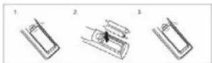
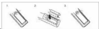
INSTALLING THE BATTERIES IN THE MICROPHONE/BELT-CLIP TRANSMITTER
Remove the battery cover and insert 2x AA size batteries ensuring correct polarity
natural_image
Three-step diagram showing a device with labeled parts, no text or symbols presentRECOMMENDATIONS FOR BATTERIES

This symbol indicates that used batteries should not be disposed of with
household waste but deposed correctly in accordance with your local regulations..
Batteries shall not be exposed to excessive heat such as sunshine, fire or the like.
When the internal batteries are not to be used, remove them to avoid damage caused by battery leakage or corrosion.
ATTENTION: Danger of explosion if battery is incorrectly placed. Only replace by the same or equivalent type.
WARNING : Keep new and old batteries out of the reach of children.
If the battery compartment doesn't close properly, stop using the product and keep it out of the reach of children.
If you are in doubt whether the batteries have been swallowed or introduced into any other part of the body, contact immediately a doctor.
INSTALLATION
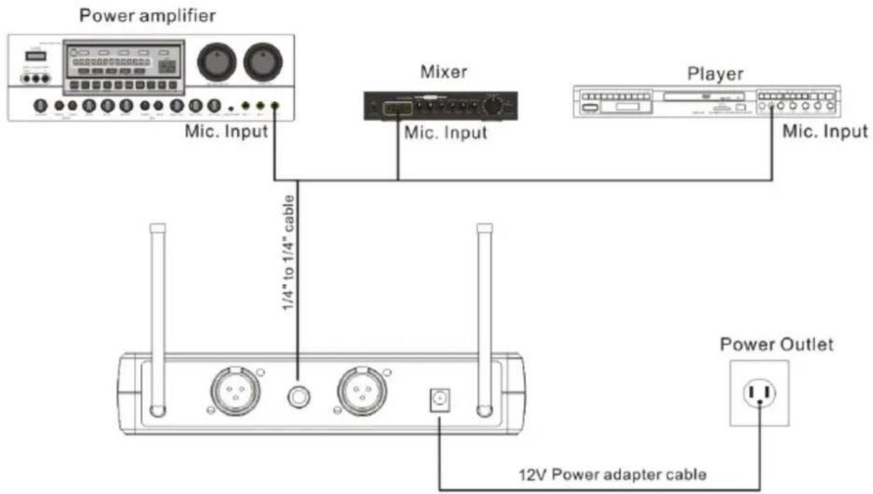
- Plug the supplied 12V= 1000mA adaptor into the DC IN socket on the rear panel and the other end into a suitable wall outlet.
- Connect one end of a 6.35mm Jack lead into the receiver's UNBALANCED audio output (MIX) and the other end into the 6.35mm mic input socket a karaoke mixer, karaoke player or karaoke amplifier. If you want to use the BALANCED audio output, please use an XLR/XLR or XLR/6.35mm Jack lead.
TROUBLE-SHOOTING
| Problem Possible Cause Solution | ||
| Receiver:No sound, no light | Power button is in the OFF positionDC power adaptor is not plugged inPoor connection of DC power adaptor | Turn on the power buttonPlug in the DC power adaptorCheck if the DC power adaptor is loose |
| MicrophoneNo sound; lights on | Transmitter is out of rangeMic is off or in Mute positionMic volume is turned downBatteries in the mic are not installed properlyAntenna not functionalReceiver is not connected to an amplifier, mixer or karaoke player | Remain within the rangeTurn mic on (green light)Increase mic volume on receiverInsert the batteries with the correct polarityChange the angle of antennaConnect the jack lead from the receiver to a mic input of an amplifier, mixer or player |
| Distorted sound; feedback | The 2 mics are too close to each otherBatteries are running lowMic volume too highDistorsion caused by an external source | Increase distance between micsReplace the batteriesReduce mic volumeMove the receiver away from electric equipment |
| Batteries | Batteries are discharged | Replace batteries |
SPECIFICATIONS
RECEIVER
UHF frequencies....863.9 & 864.9MHz
Power supply....100-240V\~ 50/60Hz via mains adaptor
Adaptor output voltage....12V= 1A
Sensitivity -105dB
S/N ratio....>105dB
THD....<0.5% à 1kHz
Image frequency rejection 85dB typical
Spurious rejection 75dB typical
Frequency range 40Hz - 18kHz
AF output impedance....2.2kOhms
Max. output level Bal.: 0-400mV; Unbal.: 0-200mV
Output connectors Bal. XLR, unbal. 6.35mm Jack
Range....10-60m
Weight...... DR20UHF-HB: 0.870kg; DR20UHF-HH: 1.05kg
TRANSMITTER
Transmission power....30mW
Spurious emission....<40dB (with carrier)
Display......LCD
Battery voltage 1.5V= x 2 pcs AA batteries
Battery life 6-8 hours
The above specifications are for reference only.
Design and specifications are subject to change for improvement without prior notice.
SYSTEME DE MICROPHONE UHF AVEC RÉCEPTEUR, MICROS & BOÎTIER CEINTURE
INTRODUCTION
EMETTEURS
MICROPHONE MAIN
INSTALLATION DES PILES DANS LE MICRO ET/OU LE BOÎTIER CEINTURE
natural_image
Three-step diagram showing a battery with three stages: initial state, intermediate state, and final state (no text or symbols)RECOMMANDATIONS POUR LES PILES

SENDER
HANMIKROFON
EINSETZEN DER BATTERIEN
natural_image
Three technical line drawings of a mechanical component or assembly, showing different views (no text or symbols present)HINWEISE FÜR BATTERIEN

ZENDERS
HAND MICROFOON
BATTERIJEN PLAATSEN
natural_image
Three-step diagram showing a battery cell with three stages: initial, intermediate, and final (no text or symbols)ADVIES VOOR BATTERIJEN

TRANSMITATOARELE
MICROFON DE MÂNĂ
(HS20-UHFA/HS20-UHFB
INSTALAREA BATERIILOR ÎN MICRO Şİ / SAU CUTIE
natural_image
Three-step diagram showing a device with a black hole, labeled 1, 2, and 3 (no text or symbols on the devices themselves)RECOMANDĂRI PENTRU BATERII

TRANSMISSORES
MICROFONE DE MÃO
TRANSMISOR DE CINTO (HS20-UHFA/HS20-UHFB
INSTALAÇÃO DAS BATERIAS NO TRANSMISSOR MICROFONE/CLIP DE CINTO
natural_image
Three schematic diagrams of electronic components or devices, labeled 1, 2, and 3, with no visible text or symbols.RECOMENDAÇÕES PARA BATERIAS

PRIJENOSNICI
RUČNI MIKROFON
- LCD zaslon
- Prekidač za napajanje
REMENSKI PREDAJNIK (HS20-UHFA/HS20-UHFB
INSTALIRANJE BATERIJA U MIKROFON / PRIKLJUČNIK
Uklonite poklopac baterije i umetnite baterije veličine 2x AA osiguravajući ispravan polaritet
natural_image
Three-step diagram showing a device with a central component, no text or symbols presentPREPORUKE ZA BATERIJE

Ovaj simbol označava da se istrošene baterije ne smiju odlagati s kućnim otpadom, već ih odlagati pravilno u skladu s lokalnim propisima.
- Uključite isporučeni adapter od 12 V= 1000 mA u utičnicu DC IN na stražnjoj ploči, a drugi kraj u odgovarajuću zidnu utičnicu.
- Spojite jedan kraj kabelskog priključka od 6,35 mm na NERASPOREDENI audio izlaz (MIX) prijemnika, a drugi kraj u ulaznu utičnicu za mikrofon od 6,35 mm, karaoke mikser, karaoke svirač ili karaoke pojačalo. Ako želite koristiti BALANCED audio izlaz, upotrijebite XLR / XLR ili XLR / 6,35 mm utičnicu.
RJEŠAVANJE PROBLEMA
Imported from China by LOTRONIC S.A.
Avenue Zénobe Gramme 9
B-1480 Saintes


www.ibiza-light.com
©Copyright LOTRONIC 2020
- MANUAL
- WITH HANDHELD, HEADSET, TIE-CLIP MIC & BELT-CLIP TRANSMITTER
- OPERATING INSTRUCTIONS
- EXPLANATION OF SIGNS
- RESTRICTIONS ON USE
- IMPORTANT SAFETY INSTRUCTIONS AND DANGER WARNINGS
- RECEIVER FRONT PANEL
- RECEIVER REAR PANEL
- TRANSMITTERS
- HANDHELD MICROPHONE
- BELT-CLIP TRANSMITTER (HS20-UHFA/HS20-UHFB
- INSTALLING THE BATTERIES IN THE MICROPHONE/BELT-CLIP TRANSMITTER
- RECOMMENDATIONS FOR BATTERIES
- INSTALLATION
- SPECIFICATIONS
- RECEIVER
- TRANSMITTER
- SYSTEME DE MICROPHONE UHF AVEC RÉCEPTEUR, MICROS & BOÎTIER CEINTURE
- INTRODUCTION
- EMETTEURS
- MICROPHONE MAIN
- INSTALLATION DES PILES DANS LE MICRO ET/OU LE BOÎTIER CEINTURE
- RECOMMANDATIONS POUR LES PILES
- HANMIKROFON
- EINSETZEN DER BATTERIEN
- HINWEISE FÜR BATTERIEN
- ZENDERS
- HAND MICROFOON
- BATTERIJEN PLAATSEN
- ADVIES VOOR BATTERIJEN
- TRANSMITATOARELE
- MICROFON DE MÂNĂ
- (HS20-UHFA/HS20-UHFB
- INSTALAREA BATERIILOR ÎN MICRO Şİ / SAU CUTIE
- RECOMANDĂRI PENTRU BATERII
- TRANSMISSORES
- MICROFONE DE MÃO
- TRANSMISOR DE CINTO (HS20-UHFA/HS20-UHFB
- INSTALAÇÃO DAS BATERIAS NO TRANSMISSOR MICROFONE/CLIP DE CINTO
- RECOMENDAÇÕES PARA BATERIAS
- RUČNI MIKROFON
- REMENSKI PREDAJNIK (HS20-UHFA/HS20-UHFB
- INSTALIRANJE BATERIJA U MIKROFON / PRIKLJUČNIK
- PREPORUKE ZA BATERIJE
- RJEŠAVANJE PROBLEMA
Brand : IBIZA SOUND
Model : DR20UHF-HH
Category : Microphone