D425-B - Ice machine Vevor - Free user manual and instructions
Find the device manual for free D425-B Vevor in PDF.

| Product type | Professional Ice Cream Machine |
| Brand | Vevor |
| Model | D425-B |
| Dimensions (approx.) | Approx. 650 x 550 x 850 mm |
| Weight (approx.) | Approx. 80 kg |
| Power supply | 220-240 V / 50 Hz, single-phase |
| Main functions | Automatic, Wash, Standby, Hardness adjustment (1-10), Restart timer, Independent refrigeration for hopper and cylinder |
| Production capacity | Approx. 15-20 liters per hour (estimate) |
| Refrigerant type | R290 (per standard) or similar |
| Maintenance and cleaning | Daily washing of cylinders, condenser cleaning every 6 months, lubrication of seals with Vaseline |
| Safety | Overload protection, hopper presence detection, automatic stop on error, FCC compliance |
| Spare parts and repairability | Nameplate, internal wiring diagram, manual with exploded view and troubleshooting guide |
| Included accessories | Dispensing door, handle, pistons, O-rings, beater, beater gasket |
| Sterilization temperature | Do not exceed 60°C |
| Warranty | Technical support at www.vevor.com/support |
Frequently Asked Questions - D425-B Vevor
User questions about D425-B Vevor
0 question about this device. Answer the ones you know or ask your own.
Ask a new question about this device
Download the instructions for your Ice machine in PDF format for free! Find your manual D425-B - Vevor and take your electronic device back in hand. On this page are published all the documents necessary for the use of your device. D425-B by Vevor.
USER MANUAL D425-B Vevor
Technical Support and E-Warranty Certificate www.vevor.com/support
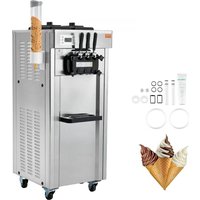
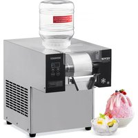
ICE CREAM MACHINE
Model:D425-B
We continue to be committed to provide you tools with competitive price. "Save Half", "Half Price" or any other similar expressions used by us only represent of savings you might benefit from buying certain tools with us compared top brands and doses not necessarily mean to cover all categories of tools offer are kindly reminded to verify carefully when you are placing an order with us actually saving half in comparison with the top major brands.
Model:D425-B
natural_image
Line drawing of a multi-compartment electrical control cabinet with cooling fans and three leads (no text or symbols)NEED HELP? CONTACT US!
Have product questions? Need technical support? Please feel fr contact us:
Technical Support and E-Warranty Certificate www.vevor.com/support
This is the original instruction, please read all manual instruction carefully before operating. VEVOR reserves a clear interpretation user manual. The appearance of the product shall be subject to product you received. Please forgive us that we won't inform your data on our product.
 | Warning-To reduce the risk of injury, user must read instructions manual carefully. |
 | This device complies with Part 15 of the FCC Rules. Operation is subject to the following two conditions:(1)T device may not cause harmful interference, and (2)this must accept any interference received, including interfer that may cause undesired operation. |
 | This product is subject to the provision of European D 2012/19/EC. The symbol showing a wheelie bin crosse through indicates that the product requires separate ref collection in the European Union. This applies to the and all accessories marked with this symbol. Products marked as such may not be discarded with normal do waste, but must be taken to a collection point for red electrical and electronic devices |

During using, service and disposal the appliance, please pa attention to symbol similar as left side, which is located on rear of appliance (rear panel or compressor) and with yellow or orange color risk of fire warning symbol. There are flammable materials in refrigera pipes and compressor. Please be far away fire source during using, service and disposal.
WARNING: Changes or modifications to this product not expressly approved by the party.responsible for compliance could void the user's authority to operate the product.
Note: This product has been tested and found to comply with the line a Class B digital device pursuant to Part 15 of the FCC Rules, The are designed to provide reasonable protection against harmful interference in a residential installation.
This product generates, uses and can radiate radio frequency energy, if not installed and used in accordance with the instructions, may cause harmful interference to radio communications. However, there is no guarantee that interference will not occur in a particular installation. If product does cause harmful interference to radio or television reception, which can be determined by turning the product off and on, user is encouraged to try to correct the interference by one or more following measures.
- Reorient or relocate the receiving antenna.
- Increase the distance between the product and receiver.
- Connect the product to an outlet on a circuit different from that to the receiver is connected.
- Consult the dealer or an experienced radio/TV technician for assistance
I.Exploded Diagram
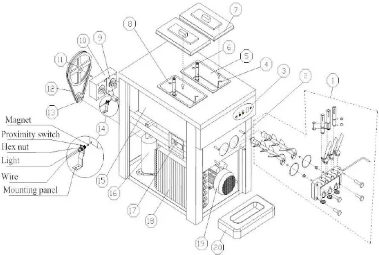
| No. | Part Name | No. | Part Name |
| 1 | Dispener Door Assembly | 12 | Belt |
| 2 | Dispenser Door Base | 13 | Drive Pulley |
| 3 | Operation Panel | 14 | Proximity Switch |
| 4 | Mix Level Probe | 15 | Evaporator |
| 5 | Hopper | 16 | Compressor |
| 6 | Feed Tube | 17 | Electrical box |
| 7 | Hopper Cover | 18 | Condenser |
| 8 | Plug of Feed Tube | 19 | Beater Motor |
| 9 | Coupling | 20 | Drip Tray |
| 10 | Gear Box | ||
| 11 | Driven Pulley |
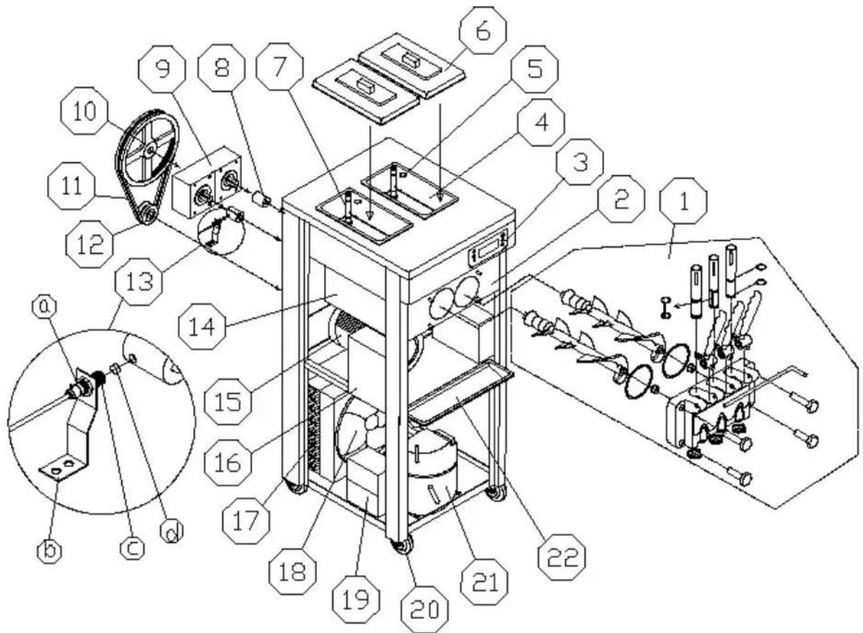
| 13a—Hex nut13b—Mounting panel | 13c—Proximity switch13d—Magnet |
| 1 | Dispenser valve(Fig.1) | 8 | Bearing sleeve | 16 | Electrical box |
| 9 | Gear motor | 17 | Condenser | ||
| 2 | Dispenser valve seat | 10 | Driven pulley | 18 | Fan motor |
| 3 | Operating panel | 11 | Belt | 19 | Capacitor of compressor |
| 4 | Hopper | 12 | Drive pulley | 20 | Wheel |
| 5 | O-ring for Feed tub | 13 | Proximity switch | 21 | Compressor |
| 6 | Cover | 14 | Evaporator | 22 | Drip tray |
| 7 | Feed tube | 15 | Beater motor |
II.Installations& Adjusting
A、unpack & inspect
1) Cut off the wrapping tape.
2) Open the wooden case by screwdriver.
3) Remove the foam.
4) Inspect carefully whether there is defective appearance or not.
5) Check the accessories with packing list.
6) Remove the fixing bolt and fixing feet that are at the bottom of machine, push the machine, let the front-wheel drive fall to the ground and then take out the wooden base, let the four wheels grounded. (I lift the machine to the ground or on the table if the machine is tab TIPS:When first time using the machine, if there remains liquid residue the cylinder.It'normal liquid residue caused by ex-factory cleaning and won't affect machine performance and its service time.If this causes a inconvenience, we feel sorry for that and thank you for your understanding.
B、Installation
a、Place the machine on a level counter that is stable and strong enough to safely support its weight.
b、Place the machine in a location that allows adequate space at the and each side for proper ventilation. Keep 50cm space from all sides ventilation. The machine should shade from the sun and should not located too close to the units that radiate excessive heat.
2) POWER SUPPLY
a、Select the proper power supply according to the voltage and power
the nameplate.
b、Connect the power wire and the power supply, ensuring the yellow green wire was connected with the ground wire firmly.

Caution: a. For safety, ensure the ground connection good condition.
b. All the exterior wires and other appliances must co with national standard.
C、Testing Running
1) Switch “ON” the power switch and you will hear “Beep”, all the graphic patterns on the screen will be lighted up and then the graphic patterns extinguish, machine enters “Standby” mode.
2) Press “Wash”, the corresponding indicator will be lighted up and at the same time you will hear the sound of beater system working. Press the “button again, beater system will stop.
3) Press “Auto”, the corresponding indicator will be lighted up and the beat system will start working. After 3 seconds, the cooling system will also start working, air pumps in both hoppers enter normal working state.
D、Clearing & Sterilizing
Step 1: Prepare 5-6 liters of warm water, mix with food detergent accord manufacture's specifications. And this is the sterilizing solution.
Step 2: Pour the solution into the hopper While the solution is flowing in freezing cylinder, brush and clean the mix hopper.
Step 3: Press the key of “clean”, and let the machine running for about minutes.
Step 4: Place an empty pail beneath the draw spout and push down the handle. Draw off all solution.
Step 5: Repeat this operation for 2-3 times with water only.

Notice: a. The temperature of the sterilizing solution can overpass 60^ C , or else it will damage the spare parts. B. Draw off all the water in the hopper after clearing, or will damage the beater while the compressor is running. C. While press the key of "clean", pay attention to the light in order to avoid pressing the wrong key.
III. Operation Instruction
A、Key Instruction
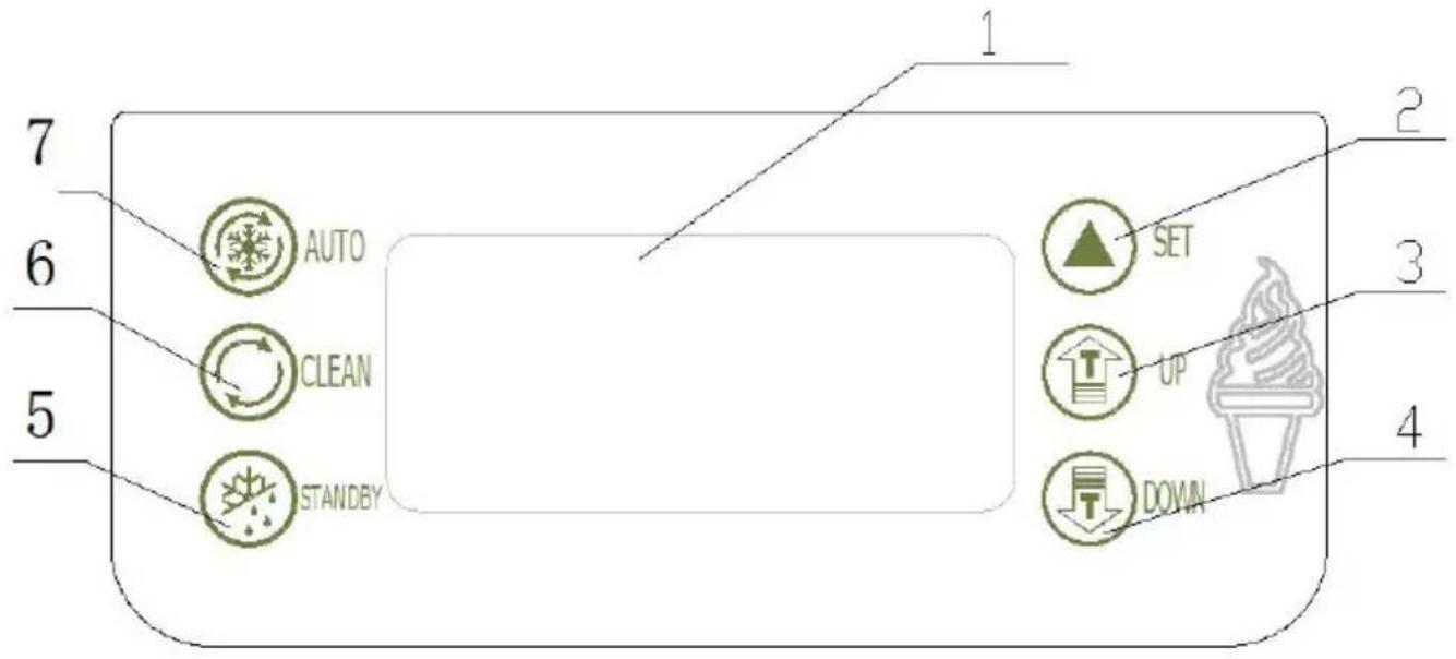
Figure.2
| 1.display screen2.set key3.adjust key(up)4.adjust key(down) | 5.standby key6.Wash key7.Auto key |
◆SET KEY(UP / DOWN)
a、set hardness level
When the machine is ready mode, press "UP" or "DOWN" key for n
than 2 seconds then the “SET” word on the displayer flashes and the number shows the setted level of hardness. For example, if the disp shows “02” it means the current setting level is 2. The stiffness will increase one level each time that the “UP” or “DOWN” key is pushed to circulate from “01” to “10”
( 01(soft)-02(hard)-03(harder)----10(hardest)-01(soft))
b、set parameters:
Machine in “standby” mode, press “UP” and “DOWN” at the same time hold for 5 seconds, the “SET” window displays “P1” icon (Periodic
Restarting Time Seeting), Press", the window will display "05"(The variable range is from "5\~15" minutes, press"UP" and "DOW" can change the setting volume)
Continue pressing “” key for two times, every time operation can cl the icon display on the window. And when each icon appears, by pre “▲”key for one time to change the setting you want.(Volume can be changed by pressing “UP” and “DOWN”)
| Icon | Implication | Variable Range |
| P1 | Periodic Restarting Time Setting | Range: 5~15 minutes |
| P2 | Stop Delay of Beater Motor | Range:5~15 seconds |
| C1 | Air Pump Working Time Setin | Range:1~30 seconds |
| C2 | Air Pump Off-Working Time Set | Range:1~30 seconds |
| P8 | Pre-Cooling temperature of the hopper | Range:1~15°C |
| P9 | Pre-Cooling temperature of the cylinder | Range:1~15°C |
Press 🔺”, the machine will enter circulatory volume setting. Without operation in ten seconds, setting volumes will be automatically saved
back to the standby mode.
Time Setting
In standby mode, press the "AUTO" and "WASH" buttons for 5 sec to the window shows "F1 01", then you can click the "UP" or "DOWN" adjust the back number. Press " " key, the window shows "F2 12", such analogy until " F7 30".
Note: F1 says mark symbol, 01、02、03……30says actual value.
F1 -- week (00 - Sunday) F2 -- year F3 - month F4 -- date
F5 -- hours F6 -- minutes F7 -- seconds
◆WASH KEY
Press wash key “”, the “CLEAR” icon light and the beater starts to. It will be closed when you press it again.
◆STANDBY KEY
Press ☐”, “STANDBY” key are on, the display hardness percentage display window shows the cylinder temperature, the display “SET” display window shows the temperature of the hopper.
◆AUTO KEY
Press standby key, “AUTO” and “FRESH” icon will light. The little compressor for hopper is controlled by setting temperature. It will stop when the temperature is less than the setting value, and it will start the tempreature in hopper raise for 2°C. The big compressor for cylinder will stops when the hardness value reach 99, after 15 seconds the motor stops. The beater motor will starts again when the time goes setting value (cycle time to restart for machine). After 3 seconds the I compressor starts.
◆PROTECTION FUNCTION
- The sensor for freezing cylinder is open circuit or short circuit, hard window on the screen will show“RL”or“RH”, the buzzer will screams at the machine stop.
- The sensor for mix hopper is open circuit or short circuit, hardness on the screen shows “RL” or “RH”, the buzzer screams, and the machine stop.
- When the machine is in “WASH” or “AUTO” mode, if the digital dis shows “— —” with alarm and machine stopping, and keys on the op panel will be locked. That means the proximity switch is damaged or correct position. Change it or put it in the correct positoin.
- When the digital display shows “NL” with alarm and machine stopping means the belt of beater motor system is skidded.
- If pushing the handle for more than 1 minute, hardness window on screen will show “Cb”, the buzzer will screams and the machine sto
- Under “AUTO” or “STANDBY” status, if mix lack, hardness window on the screen will show “CL” and hardness alternately, the buzzer will screams for 20 seconds.
•The number “01” will flash if just 1 day left for the setting cleaning. When the cleaning cycle is over, the window will shows "OVER", and buzzer works intermittently. Then you just can use "WASH" and "PUM functions. The refrigeration function is locked, and only can be unlock after switch power off and on again. The cleaning cycle will count a
- Less cooling, no cooling, or cooling over one hour still ice cream not forming, the screen will display"ERR", and sound of "BEEP" will continue
B、Make Ice Cream
1)MAKE SURE THE MACHINE IS CLEAN AND SANITIZED BEFORE MAKING ICE CREAM.
a、Prpare some sanitizing solution with warm water(temperature between 50°C and 60°C), pour it into the hopper and clean the wall of hoppe b、Turn on the power switch, and then press “ Ⓞ ” and operate for 5 minitudes.
c、Put an empty pail under the dispensing door, Pull down the handle seconds, and then return back by hand. Repeat it in this way for 6 tir clean the mix pump assembly thoroughly.
d、Draw out all sanitizing solution from machine and turn off “ ”.
e、Take off the 4 screws from dispensing door, then remove the dispensing door assembly. Disassemble it, and put them into the sanitizing solution clean thoroughly. And then assemble them together and put it on the machine.
f、Pour some clean water into the hopper and repeat to rinse it for times.
g、Use clean towel to wipe water off dispenser door.
2) PREPARE THE MIXER
Prepare the ice cream mixer as the instruction of your purchased ice cream powder or liquid mixer. Make sure the liquid mixer without any impurities or particulate. And keep it for 15 minutes or keep it into freezer.
3)MAKE ICE CREAM
Notice: When you select another new ice cream mixer to make ice cream, please set the hardness level to "02" to make ice cream. And at the hardness level properly as dispensed ice cream.
a、Pour half fresh mix into the hopper.
b、Press “unitl the inlet hole of pump cylinder without bubble. It’s n good for ice cream shape if you don’t operate in this way.
c、Add more ice cream mixer into the hopper, put the hopper coven..Press “®” key to start operation. The number on the digital display will rise up during operation. When the number reach “99”, the ice creates the freezing cylinder is ready for serve.
d、Dispensing ice cream. Put a cone or other container under the dispenser door, pull down the handle to get ice cream. Then push it back after
dispensing.
e、Clean the machine after daily work. Dispensing all the ice cream in freezing cylinder and mixer in the hopper. Clean and sanitize machine above instruction.
IV. Use & Maintenance
Different machines must be used and maintained according to their different using conditions and environment conditions.
A、Washing Refrigeration Cylinders
Clean the refrigeration cylinders once everyday for a longer useful life for the health of customers.
1) Press "© key to exhaust all the remaining slurry in the beverage containers and refrigeration cylinder, then click " " key ,the machine stop;
2) Take the right amount of food detergents, make up disinfecting solution according to it's instruction with warm water, then put the solution into each bucket;
3)Press the "◎" key, after the machine stirring about 5 minutes, discharge the disinfecting solution, followed by washing with water 2\~3 times, tr stop the machine;
4)Turn off the power, take apart and wash the parts.
a 、 Unscrew the four fastening screws in front of the dispenser dc remove the dispenser door;
b、Remove the components as follow: pin of handle, handle, piston, O-ring for piston and O-ring for dispenser door from the dispenser door; c、Draw the beater from the refrigeration tank, then remove the gask beater.
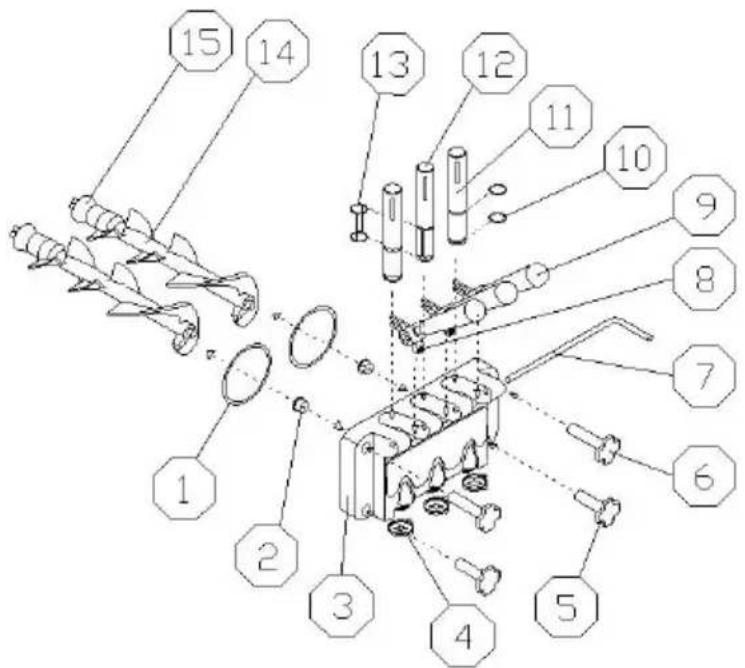
Fig.3 A
| 1.O-ring for dispenser door2.supporting sleeve3.dispensing door4.modeling cap5.down bolt | 6.upper bolt7.pin for handle8.screw for handle9.handle10.O-ring for piston | 11.piston12.middle piston13.O-ring for middle piston14.beater15.gasket for beater |
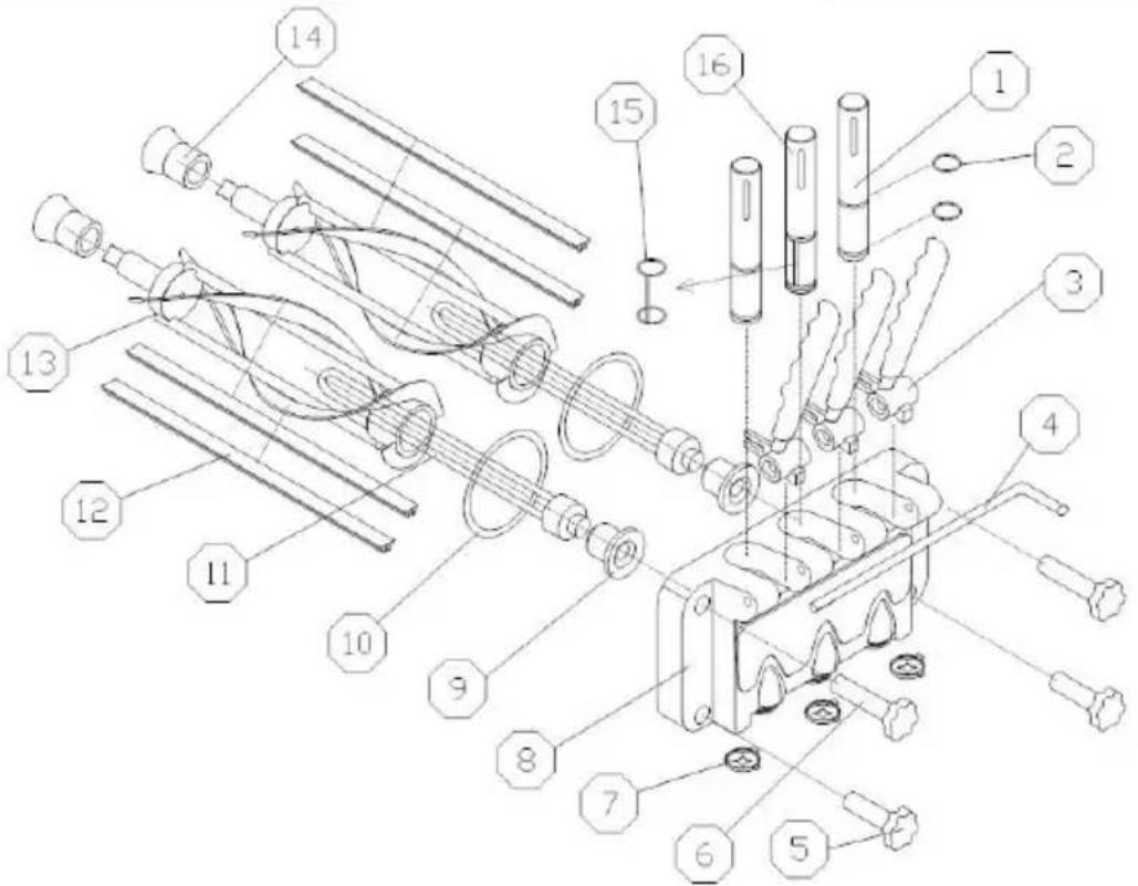
| 1.piston2.O-ring for piston3.handle4.pin of handle5.screw nut (down)6.screw nut (up)7.Modelling cap8.dispensing valve | 9.supporting sleeve10.gasket for dispensing valve11.flow plug12.blade13.beater14.gasket for beater15.New design middle piston O-rin16.New design middle piston |
d、Put the components into disinfecting solution to clean, check the beater, gasket for beater, O-ring for dispenser door, supporting sleeve and O for piston, if they are worn oldly, they should be replaced; e、After cleaning, lubricate the parts with vaseline, then install the pa according to the method of taking apart.
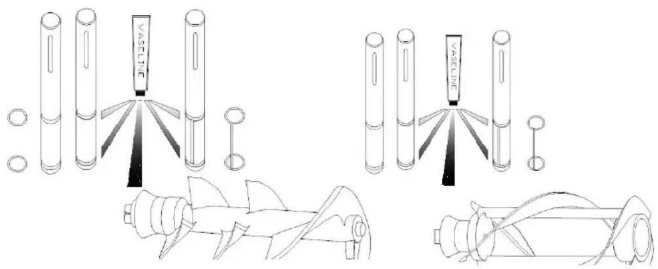
Fig.4
Notice: Before installing the piston, O-ring for piston, beater and gasket for beater, you should lubricate vaseline (lubricating vaseline onto the gro of the gasket, do not onto the beater's end ), using the vaseline free can extend the service life of components.
Notice: Before installing the piston, O-ring for piston, beater and gasket for beater, you should lubricate vaseline (lubricating vaseline onto the gro of the gasket, do not onto the beater's end ), using the vaseline free can extend the service life of components.
B、Cleaning Machine Cabinet
Keep the machine cabinet clean, use wet towel to clean the cabinet, do not flush the machine with water directly.
C、Cleaning Condenser
After be used over a period of time, the condenser may be thick with and this will effect radiate heat and cause refrigeration difference, so needs periodic cleaning (every half year)
Cleaning methods:
Step 1: Disconnected the main power switch.
Step 2: Remove the back panel and side panels.
Step 3: Clean dust with tools such as vacuum cleaner, high-pressure and hairbrush, be careful while cleaning to avoid damaging the fins of condenser.
D、Belt Adjustment
After be used over a period of time, the belt of the machine may be elongated, so it needs to be adjusted. Disconnected the main power machine, remove the back panel and side panels, adjust the tension and make sure the belt is in appropriate tension.
V.Trouble shooting guide
| Problems | Probable cause | Remedy |
| Machine does not run | Machine not plugged into the wall receptacle | Plug machine in |
| The short-circuiting switch is open | Restart it after it was reposition | |
| Protect circuit | Remove the trouble | |
| Machine in clean position does not run | The connecting wire is unfastened | Check and fasten the wire. |
| The beater motor brok | Repair or change the beater motor | |
| Mini circuit breaker wa broken. | Find and solve the problem the reposition it | |
| Machine in auto position does not run | The wire of function switch is unfastened. | Check and fasten the wire. |
| There is some problem with control panel. | Change the control panel. | |
| Compressor does not run | Low voltage | Solve the problem of low volt |
| Contactor broke | change contactor | |
| The relay of the compressor broke | Change the control panel. | |
| There is some problem with control panel. | Change the control panel. | |
| The self-protection of the compressor because of overload. | Find and solve the problem | |
| The compressor broke | Change the compressor | |
| The capacitor of the compressor broke | Change the capacitor | |
| Machine do not freeze down | Leakage of the refrigerant | Find and repair the leak in the pipe, then vacuum and rechart the refrigerant |
| Electrical valve broke | Change the electrical valve | |
| Fan motor do not run | Repair or change the fan motor | |
| The capacitor of the motor broke | Chang the capacitor of fan motor | |
| Machine non-stop | The set point is too low | Increase the set point |
| There is some problem with control panel. | Change the control panel | |
| Refrigeration difference | Check and repair the refrigerator system | |
| The relay is not stable | Low voltage | Solve the problem of low volt |
| There is some problem with control panel. | Change the control panel. | |
| The touch point of the contact switch broke. | Remove the touch point or change the contact switch. | |
| Product does not dispenser | The proportion of mix incorrect, and causes the refrigeration difference | Make up a proper proportion mix. |
| No mix in the hopper | Pour the mix into the hopper | |
| Limit switch broke or tie wire is unfastened. | Change the switch or fasten to wire | |
| The belt is unfasten of skid around | Change or adjust the belt | |
| The bearing sleeve or the beater shaft worn | Change the bearing sleeve or beater shaft. | |
| The product too soft | The proportion of the formula is wrong | Compound the mix according the formula given by the supp |
| The set point is too fast | Increase the set point | |
| Leakage | Draw piston leaking | Reassemble or change the O-ring. |
| Dispenser door leaking | Tighten the screws or change D-ring | |
| Drip tube leaking | Fix well or change the Gaske beater | |
| Warm rings | Low voltage protection | Stop the machine, solve the problem and restart 5 minutes later. |
| Stop working for protection | Stop the machine, solve the problem and restart 5 minutes later. | |
| The limit switch can return to normal | Push down the handle and le limit switch return to normal. | |
| Nixie tube display “NL” | The belt skid or the motor lose speed | Adjust or replace the belt, sol the fault of motor |
| Nixie tube display “____” | The proximity switch deflect or broke | Adjust or replace proximity sw |
VI.Schematic wiring diagram
- Technology parameters are on the nameplate
- The electrical schematic diagram is on the board inner
Made In China
VEVOR®
TOUGH TOOLS, HALF PRICE
Technical Support and E-Warranty Certificate
www.vevor.com/support
VEVOR®
TOUGH TOOLS, HALF PRICE
natural_image
Line drawing of a mechanical device with wheels and internal components (no text or symbols)BESOIN D'AIDE? CONTACTEZ-NOUS!
Fig.3 A
natural_image
Line drawing of a dual-chamber industrial machine with wheels and control panel (no text or symbols)BRAUCHEN SIE HILFE? KONTAKTIERE UNS!
Abb.3
www.vevor.com/support
VEVOR®
TOUGH TOOLS, HALF PRICE
natural_image
Line drawing of a mechanical device with wheels and internal components (no text or symbols)HO BISOGNO DI AIUTO? CONTATTACI!
Fig.3 A
elettronica www.vevor.com/support
VEVOR®
TOUGH TOOLS, HALF PRICE
natural_image
Line drawing of a mechanical device with wheels and internal components (no text or symbols)Fig.3 A
natural_image
Line drawing of a mechanical device with wheels and internal components (no text or symbols)POTRZEBUJE POMOCY? SKONTAKTUJ SIĘ Z NAMI!
- KLAWISZ SET (GÓRA / DÓŁ)
Rys.3 A
www.vevor.com/support
VEVOR®
TOUGH TOOLS, HALF PRICE
Technische ondersteuning en e-garantiecertificaat www.vevor.com/support
IJSMACHINE
Model:D425-B
natural_image
Line drawing of a mechanical device with wheels and internal components (no text or symbols)HULP NODIG? NEEM CONTACT MET ONS OP!
| 13a—Zeskantmoer13b—Montagepaneel | 13c — Naderingsschakelaar13d—Magneet |
• SET-TOETS (OMHOOG / OMLAAG)
•BESCHERMINGSFUNCTIE
Afb.3 A
www.vevor.com/support
VEVOR®
TOUGH TOOLS, HALF PRICE
natural_image
Line drawing of a dual-chamber electric shock absorber with cooling fins and mounting feet (no text or symbols)BEHÖVS HJÄLP? KONTAKTA OSS!
| 13a—Sexmutter13b—Montering av panel | 13c—Närhetsbrytare13d—Magnet |
Fig.3 A
www.vevor.com/support