CKX300PRO-A19-B - Ice machine Vevor - Free user manual and instructions
Find the device manual for free CKX300PRO-A19-B Vevor in PDF.

| Product Type | Professional Ice Machine |
| Brand | Vevor |
| Model | CKX300PRO-A19-B |
| Power Supply | Single phase 220-240 V, 50/60 Hz (estimated from standard) |
| Maximum Rated Power | 2000 W (according to manual: 16 A switch for power < 2000 W) |
| Operating Modes | Automatic, Cleaning, Night Storage, Defrost |
| Control Screen | Digital display with adjustment keys (hardness, system settings) |
| Operating Ambient Temperature | 10 °C to 38 °C |
| Maximum Relative Humidity | 90 % |
| Electrical Connection | Plug with mandatory grounding; recommended pneumatic switch (16 A single phase) |
| Cleaning and Disinfection | Daily cleaning of the system with food-grade detergent; rinse with clear water |
| Condenser Maintenance | Cleaning every 6 months with vacuum cleaner or compressed air |
| Belt Adjustment | Periodic inspection and tightening |
| Main Spare Parts | Beater, seals (piston, beater, door), belt, coupling sleeve, piston, handle |
| Safety Function | Alarms: temperature sensor, speed, belt, lack of material, overheating |
| Warranty | Electronic warranty certificate available at www.vevor.com/support |
Frequently Asked Questions - CKX300PRO-A19-B Vevor
User questions about CKX300PRO-A19-B Vevor
0 question about this device. Answer the ones you know or ask your own.
Ask a new question about this device
Download the instructions for your Ice machine in PDF format for free! Find your manual CKX300PRO-A19-B - Vevor and take your electronic device back in hand. On this page are published all the documents necessary for the use of your device. CKX300PRO-A19-B by Vevor.
USER MANUAL CKX300PRO-A19-B Vevor
Technical Support and E-Warranty Certificate www.vevor.com/support
ICE CREAM MACHINE
MODEL:CKX300PRO-A19-B
We continue to be committed to provide you tools with competitive price. "Save Half", "Half Price" or any other similar expressions used by us only repressor estimate of savings you might benefit from buying certain tools with us compared to top brands and doses not necessarily mean to cover all categories of tools offered by are kindly reminded to verify carefully when you are placing an order with us if you actually saving half in comparison with the top major brands.
MODEL: CKX300PRO-A19-B

natural_image
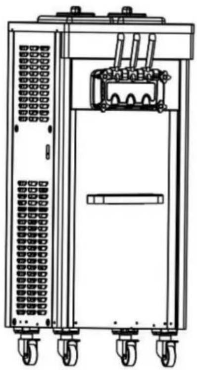
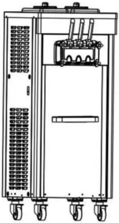
Technical line drawing of a mechanical device with wheels and internal components (no text or symbols)NEED HELP? CONTACT US!
Have product questions? Need technical support? Please feel free contact us:
Technical Support and E-Warranty Certificate www.vevor.com/support
This is the original instruction, please read all manual instructions carefully before operating. VEVOR reserves a clear interpretation of user manual. The appearance of the product shall be subject to the product you received. Please forgive us that we won't inform you there are any technology or software updates on our product.
 | Warning-To reduce the risk of injury, user must read instructions manual carefully. |
 | This device complies with Part 15 of the FCC Rules. Op is subject to the following two conditions:(1)This device not cause harmful interference, and (2)this device must ac any interference received, including interference that may cause undesired operation. |
 | This product is subject to the provision of European Dire 2012/19/EC. The symbol showing a wheelie bin crosse through indicates that the product requires separate refu collection in the European Union. This applies to the pro and all accessories marked with this symbol. Products ma as such may not be discarded with normal domestic wast must be taken to a collection point for recycling electrica electronic devices |

During using, service and disposal the appliance, please pay attention to symbol similar as left side, which is located on rear of appliance (rear panel or compressor) and with yellow or orange color. It's risk of fire warning symbol. There are flammable materials in refrigerant pipes and compressor. Please be far away fire source during using, service and disposal.
WARNING: Changes or modifications to this product not expressly approved by the party.responsible for compliance could void the user's authority to operate the product.
Note: This product has been tested and found to comply with the limits a Class B digital device pursuant to Part 15 of the FCC Rules, These I are designed to provide reasonable protection against harmful interference in a residential installation.
This product generates, uses and can radiate radio frequency energy, and if not installed and used in accordance with the instructions, may cause harmful interference to radio communications. However, there is no guarantee that interference will not occur in a particular installation. If this product does cause harmful interference to radio or television reception, which can be determined by turning the product off and on, the user is encouraged to try to correct the interference by one or more of following measures.
- Reorient or relocate the receiving antenna.
- Increase the distance between the product and receiver.
- Connect the product to an outlet on a circuit different from that to which the receiver is connected.
- Consult the dealer or an experienced radio/TV technician for assistance
I. Safety Cautions
Notice:
◆To prevent the water and other conductive liquids flow into the machin
◆Carrying or moving the machine, the maximum tilt angle is 45^
◆When the machine is working, no stick or something like that put into air grid or the dispenser door spout.
◆When the machine is running, avoid any of your body parts closing to the moving parts of the machine;
◆The machine is not allowed to operate without material (water) in the refrigeration cylinder, otherwise the mixer may be damaged;
◆It is not allowed to use water instead of liquid mix to run the machine
especially under refrigeration, to avoid freezing the cylinder and damaging the machine;
◆Recommended ratio of slurry configuration (powder: water = 1:3);
◆This machine is suitable for indoor use. Keep the indoor working environment well ventilated and heat dissipated, dry and clean, avoid heat sources and direct sunlight, and avoid places where water may splash. There should be a distance of more than 50cm between each inlet and outlet grille and walls or similar obstacles. distance;
When a freezing cylinder appears in the machine, please cut off the power, wait 30 minutes and then turn on the power again, start the clear function, lower the hardness level, and then turn on the automatic mode. The machine is equipped with a defrost function, you can directly turn or the defrost function without powering off.
Safety Warning
◆This machine is operated by professionals or trained personnel. Children are prohibited from touching, operating the machine, or playing nearby;
◆The slurry used by the machine, the environment and site used, as was the health and wear of the operator must comply with relevant food safety and hygiene laws and regulations;
◆To ensure personal safety, please ground the machine reliably;
◆When placing electrical appliances, make sure the power cord is not pinched or damaged;
◆Do not place multiple portable sockets or portable power supplies behind the machine;
◆Make sure the power supply used is the same as the nameplate on machine, and the working voltage must not deviate from the rated voltage ±10%, and the wiring must be performed by professionals;
◆If the power cord is damaged, to avoid danger, please have it replace by maintenance personnel from the manufacturer or maintenance department or similar professionals;
When the machine is connected to an external power supply, it must equipped with an air switch that can independently control the machine's power supply. If the rated power of the machine is less than 2000W, use 16A (single-phase power supply) or 10A (three-phase power supply) air switch; if the rated power is greater than 2000W, use a 32A (single-phase power supply) or 16A (three-phase power supply) air switch;
◆If the machine breaks down and needs repair, to avoid danger, please have it repaired by maintenance personnel from the manufacturer or maintenance department or similar specialized personnel;
◆Please cut off the power supply when stopping using the machine, disassembling parts or cleaning the machine;
◆To prevent electric shock, please do not soak or spill liquid on plugs, motors and other electrical components;
◆The foam layer material is flammable and users are not allowed to discard it at will or dispose of it by themselves. They should be recycled and disposed of by designated departments in accordance with relevant national regulations.
◆Do not store explosives, such as combustion accelerant sprays, in the appliance.
◆In order to protect the environment, after the packaging of this product, this product or its components are scrapped, they are collected in categories and recycled as much as possible, and the hazardous solid waste generated is disposed of legally.
II.Exploded Diagram
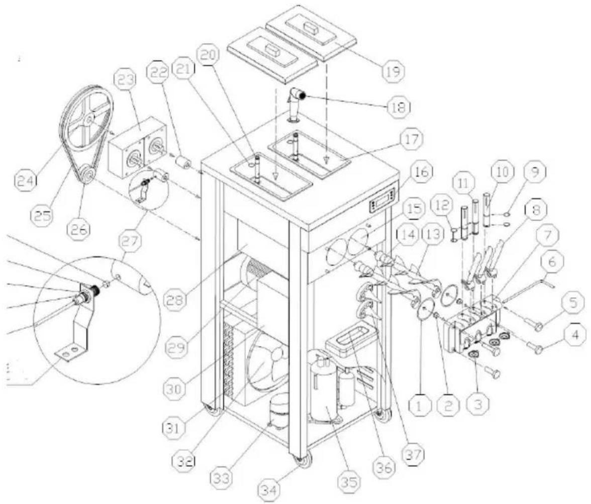
| No. | Part name | No. | Part name | No. | Part name |
| 1 | Dispenser Door Seal | 14 | Beater Gasket | 27 | Proximity Switch |
| 2 | Suportting Sleeve | 15 | Freezing Cylinder | 28 | Evaporator |
| 3 | Star Cap | 16 | Operation Panel | 29 | Beater Motor |
| 4 | Lower Fasten Screw | 17 | Mix Hopper | 30 | Compressor Accessories |
| 5 | Upper Fasten Screw | 18 | Water Faucet | 31 | Condenser |
| 6 | Pin for Handle | 19 | Hopper Cover | 32 | Fan Motor |
| 7 | Dispenser Door | 20 | Feed Tube | 33 | Pre-Cooling Compressor |
| 8 | Handle | 21 | Feed Tube O-ring | 34 | Whee |
| 9 | Piston O-ring | 22 | Coupling | 35 | Main Compressor |
| 10 | Piston | 23 | Gearbox | 36 | Drip Tray |
| 11 | Middle Piston | 24 | Driven Pulley | 37 | Cone Holder |
| 12 | Middle Piston O-ring | 25 | Pulley | ||
| 13 | Beater | 26 | Driving Pulley |
III.Installation
A. Installation
1) Open the wooden case. and then remove the fixing bolt and fixing feet that are at the bottom of the machine. Move the machine to a suitable place. Check the accessories with packing list. The machine must not til more than 450 during moving or handling.
Note: ① When the machine is first opened, a small amount of water droplets may stay in the cylinder due to the water left in the pipe when machine is cleaned in the factory, which is normal and will not affect the performance and service life of the machine. After unpacking the machine, if the handle on the machine is installed downward, please change the handle to upward to avoid affecting subsequent use.
2) Use environment
Ambient temperature: 10 \~ 38 Humidity: ≤ 90% relative humidity a, A fixed horizontal position to ensure the normal operation of the
machine, without accidents;
b, Good ventilation and cooling conditions, to avoid heat and direct sunlight. Avoid areas where water splashes may occur, with sides of air or out over 50cm from walls or similar obstructions.
3) Power Connection
a. Confirm the power type and capacity according to the nameplate marked voltage and power.
b. Make the machine power cords connect with the power according to the following requirements, and ensure yellow-green line connect with ground line. Brown line (L) connects to the hot line, blue line (N) connects to the zero line, yellow / green line power supply ground.
 Notice Notice | 1For your and others' safety and that of others, make that the machine is well grounded2 All external wiring and electrical appliances should combined with national standards.3 For a machine without a plug, the machine power can only be connected to an external power source that contains an air switch and the machine power cord is connected directly to the air switch. If machines rated i than 2000W, air switches with 16A (single-phase) or 10 (three-phase) should be used.If machines rated is more than 2000W, air switches with 32A (single-phase) or 16 (three-phase) should be used. |
B. Cleaning and Disinfection
Before the machine is used for the first time, it should be carefully disinfected and cleaned. The specific methods are as follows:
Take 5 to 6 liters of warm water, drop in an appropriate amount of food
detergent, and prepare a cleaning and disinfectant solution according to its instructions. Pour the cleaning solution into each beverage bucket and let it flow into the refrigeration cylinder. Press the "Clean" button. Run for about 5 minutes, pull down the handle, discharge the cleaning fluid through the outlet valve, repeat the above operation, and rinse with clean water 2 to 3 times.
 Notice Notice | 1. The temperature of the cleaning fluid must not exceed 60°C, otherwise parts may be easily damaged.2. All water in the cylinder must be drained after clean otherwise the mixer will be damaged by freezing during refrigeration.3. When pressing the "Clean" button, pay attention to indicator light to avoid accidentally pressing the "Auto" button. |
C. Install Feed Tube
Note: Please choose the following appropriate installation method according to the type of feeding components of the model you purchase
Feed Tube (I) Installation
a. Place the sealing ring in the groove of the feed joint. Use a small amount of Vaseline to lubricate it during installation to facilitate installation. b. Insert the holed end of the feed tube into the feed hole of the mix ho Normally
Use to expand the ice cream; if necessary, the feed tube can be installed in reverse.
To prevent the mix in the barrel from flowing into the refrigeration cylind to achieve adjusted ice cream overrun rate.
| No. | Name | 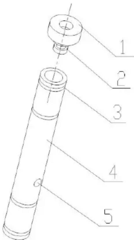 | |
| 1 | Feed Tube Plug | Optional | |
| 2 | Plug Seal | ||
| 3 | Feed Tube O-ring | ||
| 4 | Feed Tube | ||
| 5 | Feed Hole | ||

Notice
When adding mix to the hopper tank, please do not f the top of the feed tube with the mix.
Feed Tube (II) Installation
a. Place the sealing ring in the groove of the feed joint. Use a small amount of vaseline to lubricate it during installation to facilitate installation. b. Insert the inner tube of the feed tube into the outer cylinder of the feed tube in the direction shown in the figure. Pay attention to the alignment with the air inlet and feed hole of the inner tube and the outer cylinder.

c. Insert the outer cylinder of the feed tube into the feed port in the ba
When using the feed tube, you can adjust the size of the feed hole and inlet by rotating the inner tube to adjust the overrun rate of the ice cream
Note: When adjusting the aperture size of the feed tube, do not complete block the feed port and air inlet to prevent the machine from freezing due to lack of material in the refrigeration cylinder.
| No. | Name | 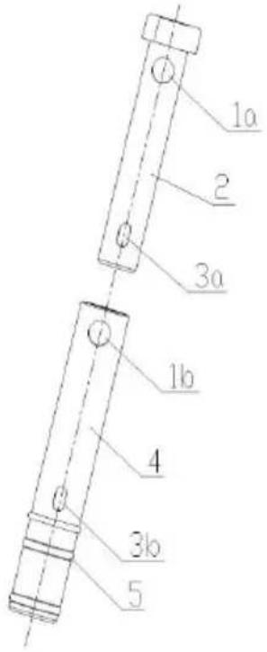 |
| 1a | Air Feed Hole | |
| 2 | Inner Tube | |
| 3a | Mix Feed Hole | |
| 1b | Air Feed Hole | |
| 4 | Outer Tube | |
| 3b | Mix Feed Hole | |
| 5 | O-ring |
Feed tube III Installation
| No. | Name | 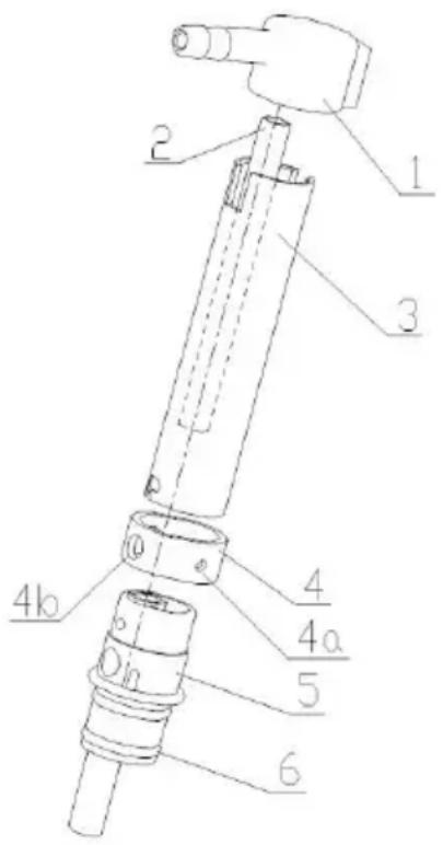 |
| 1 | Air inlet joint | |
| 2 | Feed tube inner cylinder | |
| 3 | Expanded tube outercylinder | |
| 4 | Adjustment ring | |
| 4a | Adjustment hole 1 | |
| 4b | Adjustment hole 2 | |
| 4c | Adjustment hole 3 | |
| 4d | Adjustment hole 4 | |
| 5 | Feed joint | |
| 6 | Seals |
a. Connect the air inlet joint to the air pump air pipe. You can use vast to smear the air pipe joint to facilitate the installation of the air pipe.
b. Place the sealing ring in the groove of the feed joint. Use a small amount of vaseline to lubricate it during installation to facilitate installation c. Install each component in place according to the orientation shown in the figure.
d. When using the feed tube, you can adjust the size of the mix flowing the refrigeration cylinder by rotating the different hole diameters on the adjustment ring to adjust the overrun rate of the ice cream.

When loading mix for the first time, the feeding joint must be disconnect first.
Insert it into the feed port of the hopper. Pour the mix into it in two ho the first time being the lowest mark on the wall of the hopper or just covering the bottom of the hopper. After the mix in the refrigeration cylinder is filled, insert the feed tube and pour in the remaining mix.
IV. Instructions for Use
A、Key Description
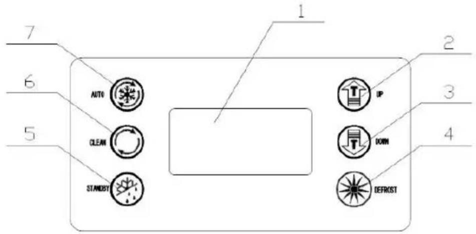 | |
| 1. Screen2. 2.UP (+)3.Down (-)4.Defrost | 5.FreshKeeping6.Clean7.Auto |
◆Adjustment Keys
a.Hardness Setting:
In standby or cooling mode, press the "+" or "-" button for 2 seconds, t window with the word "SET" will flash for seconds, and then press the ' or "-" button to change the hardness value. The range is: 1-10. If no key are operated within 5 seconds, the system automatically saves parameters and returns to standby mode.
b. System Parameter Settings:
In standby mode, press the "+" and "-" keys simultaneously for 5 seconds the "SET" window displays "P1" (machine cycle restart time setting prompt), click the "defrost" key and the window displays "05" (The range is 5-15 minutes, you can click the "UP+" and "DOWN-" keys to change value);
Click the "defrost" button again, "P2" will be displayed in the "SET" wind and so on. Each time the prompt changes, you can click the "UP" and "DOWN" keys to change the value.
| Icon | Meaning | Range |
| P1 | Machine cycle restart time setting | Range 5-15 minutes |
| P2 | Beater motor delay shutdown time setting | Range 5-15 seconds |
| P3 | Pump pump delay shutdown time setting | Range 0-15 seconds |
| P4 | Hopper pre-cooling temperature setting | Range 10-80, 10 indicating 1.0°C;80 indicating 8.0°C |
| P5 | Cylinder pre-cooling temperature setting | |
| P6 | Cleaning days setting | Range 2-14, indicating 2-14 day |
| P7 | Material shortage shutdown time setting | Range 0-10 minutes, 0 means shutdown |
| P8 | Preservation temperature hysteresis setting | Range 2-10°C, default 3°C |
| P9 | Compressor delay start time | Range 4-30 seconds, default 4 seconds |
| F1 | Air pump cycle start timesetting | Range 1-30 seconds, default 2seconds |
| F2 | Air pump cycle stop time setting | Range 0-90 seconds, default 1 seconds |
| F3 | Hopper temperature compensation value setting | Range -5.0—5.0, default 0 |
| F4 | Feezing cylinder temperature compensation value setting | Range -5.0—5.0, default 0 |
| F5 | Overlow temperature protection setting | Range 20.0-8.0Indicates -20°C--8°C, default 12 |
| F6 | Pre-cooling cycle start time setting | Range 00-30 seconds, default 1 |
| F7 | Pre-cooling cycle stop time setting | Range 0.0-8.0 minutes, default |
| F8 | FJ relay working mode | 0 or 1, 0 is the working mode the refrigeration solenoid valve. In the refrigeration and overnight preservation modes, it opens and stops at the same time as the main press solenoid valve relay 1 is the bypass solenoid valve working mode, which is opposite to the main press solenoid valve relay opening and stopping. |
| F9 | Defrost compressor working time | Range 3-9 minutes, default 6 |
Continue to click the "defrost" button to enter cycle parameter settings. I no operation within 10 seconds, the system automatically saves
parameters and returns to standby state.
c. Online detection and dispensing number display:
In the cleaning state, press and hold the "defrost" button for 5 seconds, display will display the speed. If the speed measurement is successful, t display will display "END" and the buzzer will beep once and the speed measurement value will be saved.
Dispensing number display: In standby mode, press and hold the "defrost button for 5 seconds to enter the password input state for dispensing number inquiry (P000 is displayed), the first digit flashes 0, and the mini and plus keys correspond to minus and plus changes of 0-9. Short pres the "defrost" button to switch to the second digit 0 flashing, and then, with the three-digit value corresponds to the password 222, it flashes, and the number of dispensing is displayed: ****. The digital tube of the hardness percentage of the display screen is in the thousands and hundreds digits and the digital tube of the display hardness display window is in the ter digits. It will exit after 5 seconds of no operation.
Clear the number of serving: In the state of querying the number of serving. Press and hold the "defrost" button for 5 seconds, the number of cups serving will be cleared and the buzzer will beep once. Return to the standby interface.
◆Clean
Press 📋, the beater motor starts, and the corresponding "CLEAR" icon lights up. Press💡 " again, the beater motor stops, and the corresponding "CLEAR" icon goes out.
◆Overnight Function
Press 📋, the "STANDBY" and "FRESH" icons will light up. The pre-cooling compressor is controlled by the hopper pre-cooling
temperature setting value. When the mix temperature in the hopper reaches or is lower than the hopper pre-cooling temperature setting value, the pre-cooling compressor will stop; when the temperature of the mix in the hopper rises to the hopper pre-cooling temperature setting value + 2 degrees, the pre-cooling compressor starts. When the temperature of the mix in the refrigeration cylinder reaches or is lower than the refrigeration cylinder pre-cooling temperature setting value, the main compressor stops and the beater motor stops after 15 seconds. When the mix temperature the refrigeration cylinder rises to the refrigeration cylinder pre-cooling temperature setting value + 2 degrees When, the beater motor turns on, and the main compressor turns on after 3 seconds, and so on.
◆Auto Function
Press Ⓞ, the "AUTO" and "FRESH" icons will light up. The pre-cooling press is controlled by the pre-cooling temperature setting value of the hopper. When the temperature of the mix in the hopper reaches or is lc than the pre-cooling temperature setting value of the hopper, the pre-cooling compressor will stop; when the temperature of the mix in the hopper rises to the hopper pre-cooling temperature setting value + 2 degrees, the pre-cooling compressor starts. When the hardness value reaches 99, the main compressor stops, the betaer motor stops after 15 seconds, and enters the waiting state. When the waiting time reaches th machine cycle restart time setting, the beater motor starts, and the main compressor starts after 3 seconds, and so on.
◆Defrost Function
In standby mode, press the "Defrost" button, the "AUTO" and "CLEAR" icons flash, and the machine enters the defrost function. The main compressor, beater motor, and defrost solenoid valve are controlled by
time. The beater motor starts after 1 minute; the main compressor will s after working for 5 minutes, the beater motor will stop with a delay of 3 seconds, and the defrost solenoid valve will be disconnected with a dela of 1 minute. The hardness percentage on the display shows the countdown to the remaining defrosting time, and the hardness display window on the display shows the total defrosting time. After 6 minutes (parameter F9), if no operation is performed, the machine will automatically enter standby mode.
B. Alarm Function
•The refrigeration cylinder temperature sensor alarms for open circuit or short circuit, the left display window of the display hardness percentage displays "RL" or "RH", the buzzer sounds, and the whole machine stops.
•The hopper temperature sensor alarms for open circuit or short circuit, t right display window of the display gear shows "RL" or "RH", the buzzer sounds, and the whole machine stops.
- The speed measurement proximity switch cannot detect the speed signa the hardness percentage display window of the display screen displays "——", the buzzer sounds, and the whole machine stops.
•The belt slips or the rotational speed is too low, the hardness percentage display window of the display screen displays "NL", the buzzer sounds, and the whole machine stops.
•The discharging switch is turned on for too long, the hardness percenta display window of the display screen displays "Cb", the buzzer sounds, and the whole machine stops.
• In the automatic state and overnight state, when there is lack of material in the hopper, the hardness percentage display window of the display screen alternately displays "CL" and the hardness percentage, and the buzzer stops beeping after a few seconds.
- The cooling is poor or not cooling, the machine cooling timeout (1 hour the display shows "ERR", and the buzzer beeps intermittently.
C. Making Ice Cream
1) Machine cleaning and disinfection before production.
a. Take an appropriate amount of disinfectant approved by the food hygiene license to prepare a disinfectant solution that meets the requirements (temperature between 50 and 60°C), pour it into the hopper and carefully clean all contact surfaces of the hopper;
b. Remove the slurry pump components and put them into disinfectant solution for disinfection, and carefully clean the grooves and holes of the parts;
c. Install the mix pump assembly if it has according to the above installation method of the pump assembly. Do not install the feed pipe y
d. Turn on the power switch and operate the " " button to stir for 5 minutes;
e. Place a bucket under the dispenser door, open and close the piston more than 6 times and then close the piston;
f. Release the cleaning fluid and close the " " button;
g. Remove the four fastening screws of the dispenser door, remove the piston assembly and disassemble the assembly, put it into disinfectant air clean it carefully, then assemble the assembly and install it on the machine;
h. Pour an appropriate amount of clean water into the storage tank, rephe the above steps, and rinse with clean water several times;
i. Finally, use a clean towel to wipe away the water stains on the dispedoor.
2) Mix configuration before production
Make the ice cream powder you purchased into a slurry according to its
configuration instructions. There are no unmelted particles or impurities in the slurry. After the slurry is prepared, let it stand for 15 minutes before using it, or purchase the ice cream slurry and use it directly, if any If conditions permit, you can borrow a freezer to pre-cool to about 6°C for better results (machine feed temperature: 2\~35°C).
3) Ice Cream Making
①Pour the pre-cooled ice cream mix into the hopper of the ice cream machine. There should be no lumps in the mix so that it can flow smoo into the refrigeration cylinder from the feed hole of the tube;
② When the mix flows into the refrigeration cylinder, press the " " but to start the machine and enter the AUTO working mode. You can also press the 🔊" button first to fully stir the mix, and then press the " " button;
③Operate the 🔊" key to enter the AUTO working mode. The working process can be seen on the fluorescent screen. At this time, the display value slowly increases. When it reaches more than 99% of the set hardness, it indicates that the ice cream in the corresponding refrigeration cylinder has been made;
④ To use ice cream, take a cone or other container and place it at the outlet below the dispenser door. Pull down the corresponding handle and the ice cream will squeeze out. Push the handle back later.

Note: It is necessary to ensure that there is an appropriate amount ice cream mix in the hopper of the machine. Never refrigerate when the cylinder is empty, otherwise the beater will be damaged; always check whether the feed hole of the feed tube is unobstructed to avoid clogging caused by uneven mix.
⑤Finishing work. Release the remaining mix from the machine and clear and disinfect the machine according to the above machine cleaning and
disinfection methods.
V. Daily Maintenance
The maintenance and maintenance cycle and steps are not absolutely constant. It is determined according to the actual use of the product and the environmental conditions. Each ice cream machine needs to be specifically maintained according to the actual situation.
A. Cleaning of Production System
In order to ensure the health of ice cream consumers, increase the serv life of machine parts, and avoid unnecessary trouble for you, you must carefully clean the production system every day.
1) Press the " " button to discharge all remaining mix in the hopper and refrigeration cylinder, and then press the " " button to stop the machine; 2) Take an appropriate amount of food detergent, prepare a cleaning and disinfecting solution with warm water according to its instructions, and pour it into each mix hopper;
3) Press the Ⓤ button, stir for about 5 minutes, discharge the cleaning liquid, then wash with clean water 2 to 3 times, and stop the machine;
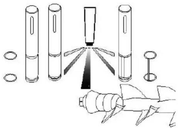
4) Turn off the power and disassemble and clean all parts. (As shown below)
a. Unscrew the four screws in front of the dispenser door and remove t dispenser door assembly;
b. Remove the handle fixing pin, handle, piston, piston o-ring, and dispenser door seals from the liquid outlet valve assembly in sequence; c.Pull out the beater from the refrigeration cylinder and remove the agita gasket.
| 1.Piston2.O-ring3.Handle4.Pin for Handle5.Lower Fasten Screw6.Upper Fasten Screw7.Star Cap | 8.Dispenser Door9.Support Sleeve10.Dispenser Door Seal11.Beater12.Beater Gasket13.Middel Piston O-ring14.Middle Piston |
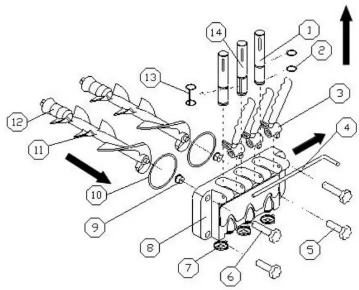
d. Put the disassembled parts into the prepared food disinfection cleaning solution and clean them one by one, and check the wear degree of the beater, gasket, dispenser door seal, support sleeve and piston o-ring. If necessary, should be replaced;
natural_image
Technical line drawing of mechanical components including cylindrical cylinders, a central pin, and a gear mechanism (no text or symbols)e. After cleaning, apply vaseline on the parts that need lubrication as shown in the figure, and install each part according to the disassembly method.

Note: When installing the piston, seals, beater and beater gasket, apply vaseline at the corresponding locations (when applying vaseline to the gasket, apply vaseline in the groove of the gasket, not on the four corners of the beater ), regular use of vaseline can extend the service life of pa
B.Machine Cleaning
In order to keep the machine beautiful, please keep the appearance of the machine clean at all times. You can wipe the machine body with a wet towel to remove stains, but do not rinse it with water to avoid electrical failure.
C. Condenser Cleaning
After the machine has been working for a period of time, the condenser will be filled with dust, affecting heat dissipation and poor cooling effect. Please clean it regularly (usually once every six months). The specific method is: turn off the power, dismantle the enclosure, and use tools such as a vacuum cleaner, high-pressure air, or a small brush to remove dus
Do not damage the condenser fins when cleaning.
D. Belt Adjustment
After the machine has been used for a period of time, the belt of the n system may be stretched and needs to be adjusted in time. When the machine is shut down and powered off, dismantle the hoarding and adjust the belt tensioning bolts to ensure proper tightness.
VI.Trouble Shooting Guide
We have listed some trouble shooting and corresponding solutions of ice cream machine in below sheet. You can follow the instruction and solve the simple issues by yourself, if the problem persists or too complex, do handle it by yourself, please contact our professional technicians to avoid any unnecessary loss.
| Issues | Causes | Treatment |
| Machine does not work. | Power cord disconnected Protection | Check the power supply and connect it securely |
| circuit breaker open | Wait for the circuit breaker to manually reset before starting again | |
| Protection circuit operation | Restart after troubleshooting | |
| Clean mode does not work. | loose connection | Check the connections and connect them securely |
| The stirring motor is broken | Repair or replace motor | |
| Mini circuit breaker tripped | After checking the cause and troubleshooting, reset | |
| AC contactor is not closed | Replace if necessary | |
| Auto mode does not work. | Function switch connection is loose | Check and connect the wires |
| The control board is fault | Replace the control board. | |
| Compressor not running | low voltage | Solve low voltage problem |
| Contactor is broken | Replace contactor | |
| Bad relay | Replace control board | |
| The control board is fault | Replace control board | |
| Compressor overload protection | Find out the cause and eliminate it | |
| Compressor is broken | Replace compressor | |
| Compressor capacitor is bad | Replace capacitor | |
| No Cooling | Refrigerant leak | Find the leak and repair it, vacuum and inject refrigerant |
| Solenoid valve broken | Replace solenoid valve | |
| Fan does not turn | Repair or replace the fan | |
| Fan capacitor is broken | Replace fan capacitor | |
| Compressor is abnormal | Check compressor and replace if necessary | |
| Non-stop | The setting hardness is too high | Turn down the hardness settin |
| The control board is fau | Replace control board | |
| Poor cooling | Overhaul refrigeration system | |
| Relay Jump | Low voltage | Solve low voltage problem |
| The control board is fau | Replace control board | |
| Contactor contacts burned out | Eliminate contacts or replace contactors | |
| No Material Discharged | The slurry ratio is incorrect causing the cylinder to freeze | Re-formulate qualified slurry |
| No material in the cylinder | Supplement ice cream mix | |
| The micro switch is broken or the connection is loose | Replace the switch or conned the wiring | |
| Belt is too loose and slipping | Adjust the belt tightness or replace the belt | |
| Worn coupling sleeve or beater | Replace coupling sleeve or agitator | |
| The ice cream is too soft | The mix ratio is wrong | Re-prepare qualified mix |
| The hardness setting is too low. | Increase the set hardness. | |
| Mix Leakage | Mix leakage from discharge hole | Install or replace valve piston seal |
| Discharge door leaking mix | Tighten the screws or replace the dispenser door seal | |
| Drip pipe leakage | Install or replace the beater gasket | |
| The buzzer beeps for a long time | Low voltage protection | Shut down for processing an restart after 5 minutes |
| Protection shutdown | Shut down for processing an restart after 5 minutes | |
| Micro switch cannot be reset in time | Push the handle to reset the micro switch | |
| "NL" is displayed. | The belt is slipping or th motor is slowing down. | Adjust the belt tightness or replace the belt, or troublesome the motor fault. |
| "—" is displayed. | The proximity switch is biased or broken. | Adjust or replace it. |
| "ERR" is displayed. | The cooling effect is pod or no cooling over one hour | Check the refrigeration system whether the compressor is working properly and whether there is fluorine leakage in the system. Please contact the nearest maintenance point. |
VII.Technical Paramater and Electrical Diagram
• Find technical parameter on the nameplate
• Find electrical diagram on the inside panel
Made In China
VEVOR®
TOUGH TOOLS, HALF PRICE
Technical Support and E-Warranty Certificate
www.vevor.com/support
VEVOR®
TOUGH TOOLS, HALF PRICE
MODÈLE : CKX300PRO-A19-B
MODÈLE : CKX300PRO-A19-B
natural_image
Technical line drawing of a mechanical device with wheels and internal components (no text or symbols)BESOIN D'AIDE? CONTACTEZ-NOUS!
natural_image
Technical line drawing of mechanical components including cylindrical cylinders, a central tool, and a gear mechanism (no text or symbols)www.vevor.com/support
VEVOR®
TOUGH TOOLS, HALF PRICE
MODELL:CKX300PRO-A19-B
MODELL:CKX300PRO-A19-B

natural_image
Technical line drawing of a mechanical device with wheels and internal components (no text or symbols)BRAUCHEN SIE HILFE? KONTAKTIERE UNS!
natural_image
Technical line drawing of mechanical components including cylindrical cylinders, a central tool, and a gear mechanism (no text or symbols)www.vevor.com/support
VEVOR®
TOUGH TOOLS, HALF PRICE
MODELLO:CKX300PRO-A19-B
MODELLO:CKX300PRO-A19-B

natural_image
Technical line drawing of a mechanical device with wheels and internal components (no text or symbols)HO BISOGNO DI AIUTO? CONTATTACI!
natural_image
Technical line drawing of mechanical components including cylindrical parts, a central spike, and a disassembled part (no text or symbols)www.vevor.com/support
VEVOR®
TOUGH TOOLS, HALF PRICE
MODELO:CKX300PRO-A19-B
MODELO:CKX300PRO-A19-B

natural_image
Technical line drawing of a mechanical device with wheels and internal components (no text or symbols)natural_image
Technical line drawing of mechanical components including cylindrical cylinders, a central tool, and a gear mechanism (no text or symbols)www.vevor.com/support
VEVOR®
TOUGH TOOLS, HALF PRICE
MODEL: CKX300PRO-A19-B
MODEL: CKX300PRO-A19-B

natural_image
Technical line drawing of a mechanical device with wheels and internal components (no text or symbols)POTRZEBUJE POMOCY? SKONTAKTUJ SIĘ Z NAMI!
natural_image
Technical line drawing of mechanical components including cylindrical parts, a central spike, and a disassembled tool (no text or symbols)www.vevor.com/support
VEVOR®
TOUGH TOOLS, HALF PRICE
Technische ondersteuning en e-garantiecertificaat www.vevor.com/support
IJSMACHINE
MODEL:CKX300PRO-A19-B
MODEL:CKX300PRO-A19-B

natural_image
Technical line drawing of a mechanical device with wheels and internal components (no text or symbols)HULP NODIG? NEEM CONTACT MET ONS OP!
natural_image
Technical line drawing of mechanical components including cylindrical parts, a central spike, and a disassembled tool (no text or symbols)www.vevor.com/support
VEVOR®
TOUGH TOOLS, HALF PRICE
MODELL: CKX300PRO-A19-B
MODELL: CKX300PRO-A19-B
natural_image
Technical line drawing of a mechanical device with wheels and internal components (no text or symbols)BEHÖVS HJÄLP? KONTAKTA OSS!
natural_image
Technical line drawing of mechanical components including cylindrical parts, a central spike, and a disassembled tool (no text or symbols)www.vevor.com/support