
Z1T-KY01-30-50 - Threading machine Vevor - Free user manual and instructions
Find the device manual for free Z1T-KY01-30-50 Vevor in PDF.
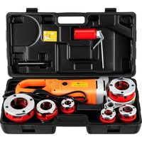


| Product Type | Electric Pipe Threading Machine |
| Brand | Vevor |
| Model | Z1T-KY01-30-50 |
| Threading Capacity | Pipes from 1/2" to 2" (depending on dies provided) |
| Power Supply | Single-phase mains (voltage per version: 120 V or 230 V) |
| Protection Class | II (double insulation) |
| Certifications | CE, FCC Part 15 |
| Rotation Speed | Not specified (typical: approx. 30-50 rpm) |
| Rotation Direction | Forward/reverse switch |
| Motor Type | Brushed electric motor |
| Included Accessories | Set of dies (6 patterns Europe or North America), plastic case, oiler, replacement carbon brushes (x2), clamp, manual |
| Recommended Cutting Oil | Thread cutting oil (not included) |
| Regular Maintenance | Clean with a damp cloth; blow out ventilation slots; replace brushes every 2 months if wear > 1/4 |
| Required Protective Equipment | Safety glasses, hearing protection, gloves, dust mask |
| Warranty | Electronic warranty certificate available at vevor.com/support |
| Country of Origin | China |
| CE Representative | SHUNSHUN GmbH, Römeräcker 9 Z2021, 76351 Linkenheim-Hochstetten, Germany |
| UK Representative | Pooledas Group Ltd, Unit 5 Albert Edward House, The Pavilions, Preston, UK |
| US Importer | Sanven Technology Ltd., Suite 250, 9166 Anaheim Place, Rancho Cucamonga, CA 91730 |
Frequently Asked Questions - Z1T-KY01-30-50 Vevor
User questions about Z1T-KY01-30-50 Vevor
0 question about this device. Answer the ones you know or ask your own.
Ask a new question about this device
Download the instructions for your Threading machine in PDF format for free! Find your manual Z1T-KY01-30-50 - Vevor and take your electronic device back in hand. On this page are published all the documents necessary for the use of your device. Z1T-KY01-30-50 by Vevor.
USER MANUAL Z1T-KY01-30-50 Vevor
Technical Support and E-Warranty Certificate www.vevor.com/support
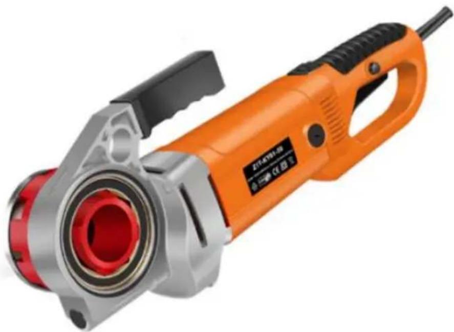
ELECTRIC PIPE THREADING MACHINE
MODEL: Z1T-KY01-30-50
We continue to be committed to provide you with tools at competitive prices. "Save Half", "Half Price" or any other similar expressions used by us only represent savings you might benefit from buying certain tools with us compared to top brands and does not necessarily mean to cover all categories of tools offered. We kindly remind you to verify carefully when placing an order with us that you are actually saving half in comparison with the top major brands.
MODEL: Z1T-KY01-30-50
NEED HELP? CONTACT US!
Have product questions? Need technical support? Please feel free to contact us:
Technical Support and E-Warranty Certificate www.vevor.com/support
This is the original instruction. Please read all manual instructions carefully before operating. VEVOR reserves a clear interpretation of the user manual. The appearance of the product shall be subject to the product you received. Please forgive us that we won't inform you of any technology or software updates on our product.
 | Warning-To reduce the risk of injury, user must read instruct manual carefully. |
    | Always wear ANSI approved safety goggles when working wi and equipment.Wear eye protection.Wear ear protection.Wear dust masksWear protective gloves. |
 | Compliance is a EC security certification. |
 | This product is of protection class II. That means it is equi enhanced or double insulation. |
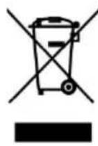 | CORRECT DISPOSALThis product is subject to the provision of European Directive 2012/19/EC. The symbol showing a wheelie bin crossed thr indicates that the product requires separate refuse collection European Union. This applies to the product and all access marked with this symbol. Products marked as such may not discarded with normal domestic waste, but must be taken to collection point for recycling electrical and electronic devices |
IMPORTANT SAFEGUARDS
WARNING: Read all safety warnings, instructions, illustrations and specifications
provided with this power tool. Failure to follow all instructions listed below may result in electric shock, fire and/or serious injury.
Save all warnings and instructions for future reference.
Work area safety
a) Keep work area clean and well lit. Cluttered or dark areas invite accidents.
b) Do not operate power tools in explosive atmospheres, such as in the presence of flammable liquids, gases or dust. Power tools create sparks which may ignite the dust or fumes.
c) Keep children and bystanders away while operating a power tool. Distractions can cause you to lose control.
Electrical safety
a) Power tool plugs must match the outlet. Never modify the plug in any way, and do not use any adapter plugs with earthed (grounded) power tools. Unmodified plugs and matching outlets will reduce the risk of electric shock.
b) Avoid body contact with earthed or grounded surfaces, such as pipes, radiators, ranges and refrigerators. There is an increased risk of electric shock if your body is earthed or grounded.
c) Do not expose power tools to rain or wet conditions. Water entering a power tool will increase the risk of electric shock.
d) Do not abuse the cord. Never use the cord for carrying, pulling or unplugging the power tool. Keep cord away from heat, oil, sharp edges or moving parts. Damaged or entangled cords increase the risk of electric shock.
e) When operating a power tool outdoors, use an extension cord suitable for outdoor use. Use of a cord suitable for outdoor use reduces the risk of electric shock.
f) If operating a power tool in a damp location is unavoidable, use a residual current device (RCD) protected supply. Use of an RCD reduces the risk of electric shock.
Personal safety
a) Stay alert, watch what you are doing and use common sense when operating a power tool. Do not use a power tool while you are tired or under the influence of drugs, alcohol or medication. A moment of inattention while operating power tools may result in serious personal injury.
b) Use personal protective equipment. Always wear eye protection. Protective equipment such as a dust mask, non-skid safety shoes, hard hat or hearing protection used for appropriate conditions will reduce personal injuries.
c) Prevent unintentional starting. Ensure the switch is in the off-position before connecting to power source and/or battery pack, picking up or carrying the tool. Carrying power tools with your finger on the switch or energising power tools that have the switch on invites accidents. d) Remove any adjusting key or wrench before turning the power tool on. A wrench or a key left attached to a rotating part of the power tool may result in personal injury. e) Do not overreach. Keep proper footing and balance at all times. This enables better control of the power tool in unexpected situations. f) Dress properly. Do not wear loose clothing or jewellery. Keep your hair and clothing away from moving parts. Loose clothes, jewellery or long hair can be caught in moving parts. g) If devices are provided for the connection of dust extraction and collection facilities, ensure these are connected and properly used. Use of dust collection can reduce dust-related hazards. h) Do not let familiarity gained from frequent use of tools allow you to become complacent and ignore tool safety principles. A careless action can cause severe injury within a fraction of a second.
Power tool use and care
a) Do not force the power tool. Use the correct power tool for your application. The correct power tool will do the job better and safer at the rate for which it is designed. b) Do not use the power tool if the switch does not turn it on and off. Any power tool that cannot be controlled with the switch is dangerous and must be repaired. c) Disconnect the plug from the power source and/or remove the battery pack, if detachable, from the power tool before making any adjustments, changing accessories, or storing power tools. Such preventive safety measures reduce the risk of starting the power tool accidentally. d) Store idle power tools out of the reach of children and do not allow persons unfamiliar with the power tool or these instructions to operate the power tool. Power tools are dangerous in the hands of untrained users.
e) Maintain power tools and accessories. Check for misalignment or binding of moving parts, breakage of parts and any other condition that may affect the tool's operation. If damaged, have the power tool repaired before use. Many accidents are caused by poorly maintained power tools.
f) Keep cutting tools sharp and clean. Properly maintained cutting tools with sharp cutting edges are less likely to bind and are easier to control.
g) Use the power tool, accessories and tool bits etc. in accordance with these instructions, taking into account the working conditions and the work to be performed. Use of the power tool for operations different from those intended could result in a hazardous situation.
h) Keep handles and grasping surfaces dry, clean and free from oil and grease. Slippery handles and grasping surfaces do not allow for safe handling and control of the tool in unexpected situations.
Service
Have your power tool serviced by a qualified repair person using only identical replacement parts. This will ensure that the safety of the power tool is maintained.
SAVE THESE INSTRUCTIONS
FCC Information
CAUTION:
Changes or modifications not expressly approved by the party responsible for compliance could void the user's authority to operate the equipment!
This device complies with Part 15 of the FCC Rules. Operation is subject to the following two conditions:
1) This product may cause harmful interference.
2) This product must accept any interference received, including interference that may cause undesired operation.
WARNING:
Changes or modifications to this product not expressly approved by the party responsible for compliance could void the user's authority to operate the product.
Note:
This product has been tested and found to comply with the limits for a Class B digital device pursuant to Part 15 of the FCC Rules. These limits are designed to provide reasonable protection against harmful interference in a residential installation.
This product generates, uses and can radiate radio frequency energy, and if installed and used in accordance with the instructions, may cause harmful interference to radio communications. However, there is no guarantee that interference will not occur in a particular installation. If this product does cause harmful interference to radio or television reception, which can be determined by turning the product off and on, the user is encouraged to try to correct the interference by one or more of the following measures.
- Reorient or relocate the receiving antenna.
- Increase the distance between the product and receiver.
- Connect the product to an outlet on a circuit different from that to which the receiver is connected.
- Consult the dealer or an experienced radio/TV technician for assistance.
PRODUCT PARAMETERS
| MODEL | Electrical parameters | velocity | Die size |
| Z1T-KY01-30-50 | European Union: AC220-230V 50Hz 2300W | 26/rpm | BSPT: 1/2"、3/4"、1"、1-1/4"、1-1/2"、2" |
| North America: AC120V 60Hz 2300W | NPT: 1/2"、3/4"、1"、1-1/4"、1-1/2"、2" | ||
| North America: AC120V 60Hz 2300W | NPT: 1/2"、3/4"、1"、1-1/4" |
Sanding belt Optional Equipment
A: 6 die models in Europe
Plastic box x1, oil pot x 1, carbon brush x 2, fixture x 1, manual x 1
B: 6 die models in North America:
Plastic box x1, oil pot x 1, carbon brush x 2, fixture x 1, manual x 1
C: 4 die models in North America:
Plastic box x1, oil pot x1, carbon brush x2, fixture x1, manual x1
OPERATION
- Press the bottom of the screwing die head spline down and put it into three worm gears until it is fixed by the spring.
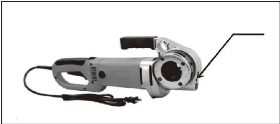
Caution: It should be injected with grease gun proper grease into the hole with thirty days.
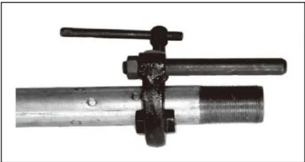
- Fasten the pipe to the three-legged support pincers or the bench vice. Caution: Support arm can be used and the pipe must be fixed when threading pipes whose diameter is bigger than 3/4". Every surpasses 1-1/4 " the pipeline processes when must add the fixed p Otherwise is easy to create the machine damage.
- Attach support arm tightly to the pipe to ensure that the top of torque scissors parallels the top of the pipe.
Hold the electric threader handle tightly with one hand and apply force on three with help of torque.
- Place screwing die head to one side of the pipe to ensure that electric th stands a proper position on support arm .Make sure that die head rotates clockwise when threading. When the threader is held with one hand, move th head close to the pipe, start themachine, then apply force on the die head another hand until two or three threads are cut. Then stop applying force. Note: Be sure that enough cutting oil is available when threading the pipe.
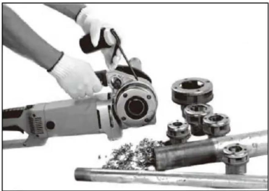
- Turn switch on and keep it down until the screw chaser surface rim occurs top of the pipe. Turn the switch off and to cut the electric threader off.
- Reverse the direct reversing switch to remove the screwing die head. Caution: Hold the threader handle tightly to bear the start torque.
Operating and Suggestion
- The electric threader is intended for threading. Be sure to follow the instructions in the manual to avoid accidents.
- Blunt or broken die heads are forbidden. A sharp knife is better.
- Secure the electric threader with support arms to keep it under control.
- The electric threader must not be used if the momentary contact switch is damaged.
- Keep the handle dry and clean, and free of oil or lubricant.
- Fix and support workpieces with grip holders or other devices on a stable platform. Do not hold workpieces with your hands.
Do not lean them against the operator.
Unreliable fastening can cause workpieces to go out of control.
- Do not apply excessive pressure to tools. Use the right tools.
- Tools that cannot be switched on or off are forbidden. Using such tools is dangerous. Switch the electric power off before adjusting, replacing, or installing workpieces. This safety measure will prevent workpieces from starting unexpectedly.
- Keep tools out of the reach of children and persons without special training when they are not in use to avoid danger.
- Keep tools in good maintenance. Keep the knife sharp.
- Examine the unsymmetry, connection, and damage of the moving parts. Broken tools are forbidden unless they are in good repair.
- Check insulation property of this machine and its wires. Replace the damaged ones.
Faults and remedies
| Fault | Cause | Remedy |
| The motor does not run | The threader is not connected with power | Insert the plug into the power seat. |
| The fuse is blown | Replace the fuse | |
| The electric brush does not contact the rotor | Check the electric brush and replace it if it is broken | |
| The motor can not bear the load. | The blunt screwing die leads to overload. | Replace the die. |
| The cutting rim of thread is not qualified. | Use threading cutting oil | |
| The inside of the motor sparks. | There is a loose contact between brushes. | Fasten the screws to make sure the electric brush is closely attached to the rectifier. |
| The screwing die head does not thread | Screwing dies become blunt or broken | Replace the die. |
| The machine rotates in wrong direction. | Check direct reversing switch devices. | |
| The screwing die is not properly placed. | Replace the die. | |
| The threads are broken | The screwing die is blunt. | Replace the die. |
| Threading dies are not placed according to sequence codes. | Place dies in right sequence. | |
| The pipes are not qualified | Use high-quality pipes only | |
| Insufficient or unqualified cutting | Use ample cutting oil | |
| Support arm rotates when cutting the threads. | Claws of support arm are not clean or are covered with waste. | Clean it with a file steel brush. |
| Screwing die heads can not be replaced. | There is burr in die grooves. | Remove the burr with a file |
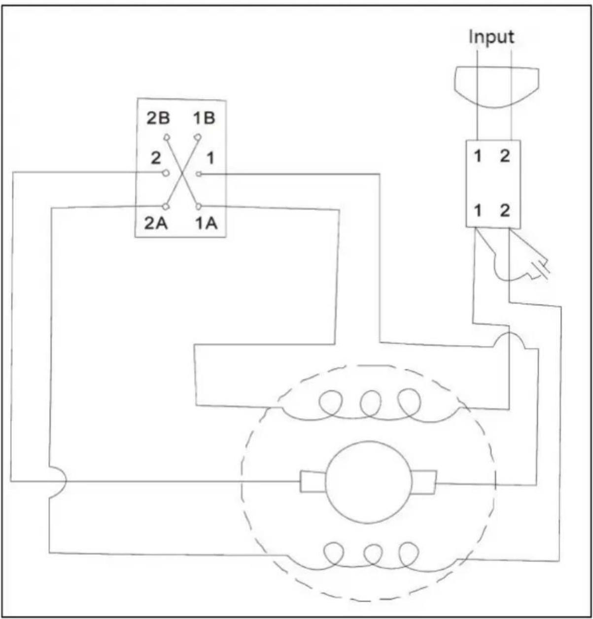
Threader's Schematic Diagram
Cleaning, Maintenance, and Lubrication
--For cleaning, wipe the surface with a damp (not wet) cloth or wipe with a clean lint-free cotton cloth.
--DURING USE, ensure that pipe end and die threads are oiled with Thread Cutting Oil (not included) at all times.
-- Worn die blades will result in poor thread quality. If the blade is worn, replace it with a qualified technician.
Motor cleaning: blow compressed air through the rear ventilation slots of the machine regularly, frequently and thoroughly. Here, the machine must be held firmly.
Replacing electric brush: Check the electric brush of the motor every two months. Replace it when the part that is worn out is more than 1/4.
Address: Baoshanqu Shuangchenglu 803long 11hao 1602A-1609shi Shanghai
Imported to USA: Sanven Technology Ltd. Suite 250, 9166 Anaheim Place, Rancho Cucamonga, CA 91730
| UK | REP |
Pooledas Group Ltd
Unit 5 Albert Edward House, The Pavilion
Preston, United Kingdom
| EC | REP |
SHUNSHUN GmbH
Römeräcker 9 Z2021, 76351
Technical Support and E-Warranty Certificate www.vevor.com/support
VEVOR®
TOUGH TOOLS, HALF PRICE
NEED HELP? CONTACT US!
PRODUCT PARAMETERS
| MODÈLE | Électrique paramètres | vitesse | Taille de la matrice |
| Z1T-KY01-30-50 | Union européenne :CA 220-230 V 50 Hz2300 W | 26/tr/min | BSPT : 1/2" 3/4"1", 1-1/4", 1-1/2",2" |
| Amérique du Nord:CA 120 V 60 Hz2300 W | NPT : 1/2", 3/4",1", 1-1/4", 1-1/2",2" | ||
| Amérique du Nord:CA 120 V 60 Hz2300 W | NPT : 1/2", 3/4",1", 1-1/4" |
Die (BSPT): 1/2" x 1 3/4" x 1 1" x 1 1-1/4" x 1 1-1/2" x 1 2" x 1
Die (NPT): 1/2" x 1 3/4" x 1 1" x 1 1-1/4" x 1 1-1/2" x 1 2" x 1
Die (NPT): 1/2" x 1 3/4" x 1 1" x 1 1-1/4" x 1
| Fault | Cause | Remedy |
| The motor does not run | The threader is not connected with power | Insert the plug into the power seat. |
| The fuse is blown | Replace the fuse | |
| The electric brush does not contact the rotor | Check the electric brush and replace it if it is broken | |
| The motor can not bear the load. | The blunt screwing die leads to overload. | Replace the die. |
| The cutting rim of thread is not qualified. | Use threading cutting oil | |
| The inside of the motor sparks. | There is a loose contact between brushes. | Fasten the screws to make sure the electric brush is closely attached to the rectifier. |
| The screwing die head does not thread | Screwing dies become blunt or broken | Replace the die. |
| The machine rotates in wrong direction. | Check direct reversing switch devices. | |
| The screwing die is not properly placed. | Replace the die. | |
| The threads are broken | The screwing die is blunt. | Replace the die. |
| Threading dies are not placed according to sequence codes. | Place dies in right sequence. | |
| The pipes are not qualified | Use high-quality pipes only | |
| Insufficient or unqualified cutting | Use ample cutting oil | |
| Support arm rotates when cutting the threads. | Claws of support arm are not clean or are covered with waste. | Clean it with a file steel brush. |
| Screwing die heads can not be replaced. | There is burr in die grooves. | Remove the burr with a file |
| Fault | Cause | Remedy |
| The motor does not run | The threader is not connected with power | Insert the plug into the power seat. |
| The fuse is blown | Replace the fuse | |
| The electric brush does not contact the rotor | Check the electric brush and replace it if it is broken | |
| The motor can not bear the load. | The blunt screwing die leads to overload. | Replace the die. |
| The cutting rim of thread is not qualified. | Use threading cutting oil | |
| The inside of the motor sparks. | There is a loose contact between brushes. | Fasten the screws to make sure the electric brush is closely attached to the rectifier. |
| The screwing die head does not thread | Screwing dies become blunt or broken | Replace the die. |
| The machine rotates in wrong direction. | Check direct reversing switch devices. | |
| The screwing die is not properly placed. | Replace the die. | |
| The threads are broken | The screwing die is blunt. | Replace the die. |
| Threading dies are not placed according to sequence codes. | Place dies in right sequence. | |
| The pipes are not qualified | Use high-quality pipes only | |
| Insufficient or unqualified cutting | Use ample cutting oil | |
| Support arm rotates when cutting the threads. | Claws of support arm are not clean or are covered with waste. | Clean it with a file steel brush. |
| Screwing die heads can not REINIGUNG be replaced. | There is burr in die grooves. UND WARTUNG | Remove the burr with a file |
| Fault | Cause | Remedy |
| The motor does not run | The threader is not connected with power | Insert the plug into the power seat. |
| The fuse is blown | Replace the fuse | |
| The electric brush does not contact the rotor | Check the electric brush and replace it if it is broken | |
| The motor can not bear the load. | The blunt screwing die leads to overload. | Replace the die. |
| The cutting rim of thread is not qualified. | Use threading cutting oil | |
| The inside of the motor sparks. | There is a loose contact between brushes. | Fasten the screws to make sure the electric brush is closely attached to the rectifier. |
| The screwing die head does not thread | Screwing dies become blunt or broken | Replace the die. |
| The machine rotates in wrong direction. | Check direct reversing switch devices. | |
| The screwing die is not properly placed. | Replace the die. | |
| The threads are broken | The screwing die is blunt. | Replace the die. |
| Threading dies are not placed according to sequence codes. | Place dies in right sequence. | |
| The pipes are not qualified | Use high-quality pipes only | |
| Insufficient or unqualified cutting | Use ample cutting oil | |
| Support arm rotates when cutting the threads. | Claws of support arm are not clean or are covered with waste. | Clean it with a file steel brush. |
| Screwing die heads can not be replaced. | There is burr in die grooves. | Remove the burr with a file |
Die (BSPT): 1/2" x 1 3/4" x 1 1" x 1 1-1/4" x 1 1-1/2" x 1 2" x 1
Die (NPT): 1/2" x 1 3/4" x 1 1" x 1 1-1/4" x 1 1-1/2" x 1 2" x 1
Die (NPT): 1/2" x 1 3/4" x 1 1" x 1 1-1/4" x 1
| Fault | Cause | Remedy |
| The motor does not run | The threader is not connected with power | Insert the plug into the power seat. |
| The fuse is blown | Replace the fuse | |
| The electric brush does not contact the rotor | Check the electric brush and replace it if it is broken | |
| The motor can not bear the load. | The blunt screwing die leads to overload. | Replace the die. |
| The cutting rim of thread is not qualified. | Use threading cutting oil | |
| The inside of the motor sparks. | There is a loose contact between brushes. | Fasten the screws to make sure the electric brush is closely attached to the rectifier. |
| The screwing die head does not thread | Screwing dies become blunt or broken | Replace the die. |
| The machine rotates in wrong direction. | Check direct reversing switch devices. | |
| The screwing die is not properly placed. | Replace the die. | |
| The threads are broken | The screwing die is blunt. | Replace the die. |
| Threading dies are not placed according to sequence codes. | Place dies in right sequence. | |
| The pipes are not qualified | Use high-quality pipes only | |
| Insufficient or unqualified cutting | Use ample cutting oil | |
| Support arm rotates when cutting the threads. | Claws of support arm are not clean or are covered with waste. | Clean it with a file steel brush. |
| Screwing die heads can not be replaced. | There is burr in die grooves.MANTENIMIENTO | Remove the burr with a file |
NEED HELP? CONTACT US!
| Fault | Cause | Remedy |
| The motor does not run | The threader is not connected with power | Insert the plug into the power seat. |
| The fuse is blown | Replace the fuse | |
| The electric brush does not contact the rotor | Check the electric brush and replace it if it is broken | |
| The motor can not bear the load. | The blunt screwing die leads to overload. | Replace the die. |
| The cutting rim of thread is not qualified. | Use threading cutting oil | |
| The inside of the motor sparks. | There is a loose contact between brushes. | Fasten the screws to make sure the electric brush is closely attached to the rectifier. |
| The screwing die head does not thread | Screwing dies become blunt or broken | Replace the die. |
| The machine rotates in wrong direction. | Check direct reversing switch devices. | |
| The screwing die is not properly placed. | Replace the die. | |
| The threads are broken | The screwing die is blunt. | Replace the die. |
| Threading dies are not placed according to sequence codes. | Place dies in right sequence. | |
| The pipes are not qualified | Use high-quality pipes only | |
| Insufficient or unqualified cutting | Use ample cutting oil | |
| Support arm rotates when cutting the threads. | Claws of support arm are not clean or are covered with waste. | Clean it with a file steel brush. |
| Screwing die heads can not CZYSZCZENIE I be replaced. | There is burr in die grooves. KONSERWACJA | Remove the burr with a file |
NEED HELP? CONTACT US!
| Fault | Cause | Remedy |
| The motor does not run | The threader is not connected with power | Insert the plug into the power seat. |
| The fuse is blown | Replace the fuse | |
| The electric brush does not contact the rotor | Check the electric brush and replace it if it is broken | |
| The motor can not bear the load. | The blunt screwing die leads to overload. | Replace the die. |
| The cutting rim of thread is not qualified. | Use threading cutting oil | |
| The inside of the motor sparks. | There is a loose contact between brushes. | Fasten the screws to make sure the electric brush is closely attached to the rectifier. |
| The screwing die head does not thread | Screwing dies become blunt or broken | Replace the die. |
| The machine rotates in wrong direction. | Check direct reversing switch devices. | |
| The screwing die is not properly placed. | Replace the die. | |
| The threads are broken | The screwing die is blunt. | Replace the die. |
| Threading dies are not placed according to sequence codes. | Place dies in right sequence. | |
| The pipes are not qualified | Use high-quality pipes only | |
| Insufficient or unqualified cutting | Use ample cutting oil | |
| Support arm rotates when cutting the threads. | Claws of support arm are not clean or are covered with waste. | Clean it with a file steel brush. |
| Screwing die heads can not be replaced. | There is burr in die grooves. | Remove the burr with a file |
Schematic diagram of Threader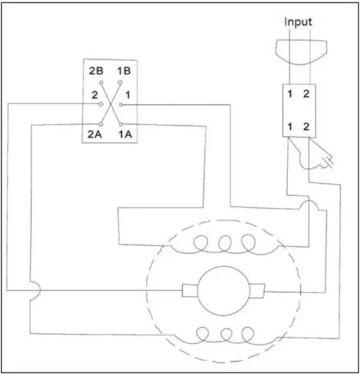
Unit 5 Albert Edward House, The Pavilions
| Fault | Cause | Remedy |
| The motor does not run | The threader is not connected with power | Insert the plug into the power seat. |
| The fuse is blown | Replace the fuse | |
| The electric brush does not contact the rotor | Check the electric brush and replace it if it is broken | |
| The motor can not bear the load. | The blunt screwing die leads to overload. | Replace the die. |
| The cutting rim of thread is not qualified. | Use threading cutting oil | |
| The inside of the motor sparks. | There is a loose contact between brushes. | Fasten the screws to make sure the electric brush is closely attached to the rectifier. |
| The screwing die head does not thread | Screwing dies become blunt or broken | Replace the die. |
| The machine rotates in wrong direction. | Check direct reversing switch devices. | |
| The screwing die is not properly placed. | Replace the die. | |
| The threads are broken | The screwing die is blunt. | Replace the die. |
| Threading dies are not placed according to sequence codes. | Place dies in right sequence. | |
| The pipes are not qualified | Use high-quality pipes only | |
| Insufficient or unqualified cutting | Use ample cutting oil | |
| Support arm rotates when cutting the threads. | Claws of support arm are not clean or are covered with waste. | Clean it with a file steel brush. |
| Screwing die heads can not be replaced. | There is burr in die grooves. | Remove the burr with a file |
Unit 5 Albert Edward House, The Pavilions
- ELECTRIC PIPE THREADING MACHINE
- NEED HELP? CONTACT US
- IMPORTANT SAFEGUARDS
- WORK AREA SAFETY
- ELECTRICAL SAFETY
- PERSONAL SAFETY
- POWER TOOL USE AND CARE
- SERVICE
- SAVE THESE INSTRUCTIONS
- FCC INFORMATION
- CAUTION
- WARNING
- NOTE
- SANDING BELT OPTIONAL EQUIPMENT
- A: 6 DIE MODELS IN EUROPE
- B: 6 DIE MODELS IN NORTH AMERICA
- C: 4 DIE MODELS IN NORTH AMERICA
- OPERATION
- OPERATING AND SUGGESTION
- THREADER'S SCHEMATIC DIAGRAM
- CLEANING, MAINTENANCE, AND LUBRICATION
- VEVOR®
- TOUGH TOOLS, HALF PRICE
Brand : Vevor
Model : Z1T-KY01-30-50
Category : Threading machine