
QBY4-50L - Air pump Vevor - Free user manual and instructions
Find the device manual for free QBY4-50L Vevor in PDF.
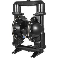


| Product Type | Pneumatic double diaphragm pump |
| Model | QBY4-50L |
| Brand | Vevor |
| Operating principle | Pneumatic double diaphragm, no rotating parts |
| Inlet/Outlet | 50 mm (flange) |
| Max suction height | 7 m |
| Max discharge height | 50 m |
| Max outlet pressure | > 6 kgf/cm² |
| Max particle diameter | 10 mm |
| Max fluid viscosity | 10,000 cP |
| Compressed air pressure | 2 to 8 kgf/cm² |
| Materials in contact with fluid | Stainless steel, aluminum alloy, cast iron, engineering plastic |
| Diaphragm materials | NBR, Viton, Neoprene, PTFE |
| Power supply | Compressed air (no electricity) |
| Self-priming | Yes, up to 7 m |
| Main applications | Transfer of corrosive, viscous, flammable liquids, sludges, foodstuffs (chocolate, syrup), paint, glue, etc. |
| Maintenance | Clean the interior cavity and copper bushing when replacing the diaphragm |
| Safety | Spark-free, usable in explosive atmospheres |
| Spare parts | Diaphragms, valves, seals available from the manufacturer |
| Repairability | Simple structure, easy replacement of diaphragms and valves |
Frequently Asked Questions - QBY4-50L Vevor
User questions about QBY4-50L Vevor
0 question about this device. Answer the ones you know or ask your own.
Ask a new question about this device
Download the instructions for your Air pump in PDF format for free! Find your manual QBY4-50L - Vevor and take your electronic device back in hand. On this page are published all the documents necessary for the use of your device. QBY4-50L by Vevor.
USER MANUAL QBY4-50L Vevor
Air Operated Double Diaphragm Pump Instructions
MODEL: QBK-40L / QBY4-50L / QBY4-25L / QBY4-25LF46 / QBY-15PP / QBK-15P / QBK-15
We continue to be committed to provide you tools with competitive price. "Save Half", "Half Price" or any other similar expressions used by us only represent the estimate of savings you might benefit from buying certain tools with us compared to top brands and does not necessarily mean to cover all categories of tools offered. We are kindly reminded to verify carefully when you are placing an order with us actually saving half in comparison with the top major brands.
VEVOR®
TOUGH TOOLS, HALF PRICE
Air Operated Double Diaphragm Pump
MODEL: QBK-40L/QBY4-50L/QBY4-25L/QBY4-25LF46/QBY-15PP/QBK-15P/QBK-15
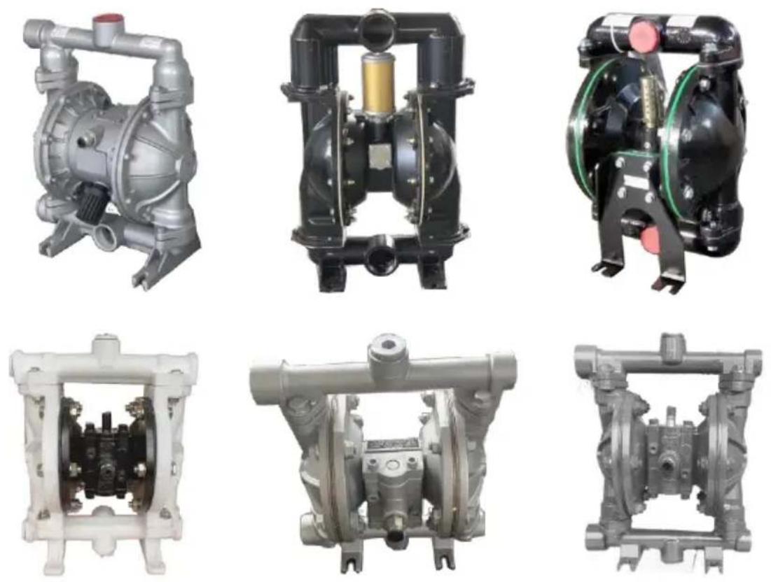
NEED HELP? CONTACT US!
Have product questions? Need technical support? Please feel free to contact us:
This is the original instruction, please read all manual instruction carefully before operating. VEVOR reserves a clear interpretation user manual. The appearance of the product shall be subject to product you received. Please forgive us that we won't inform you there are any technology or software updates on our product.

Warning - To reduce the risk of injury, user must read instructions manual carefully.
PRODUCT PRESENTATION
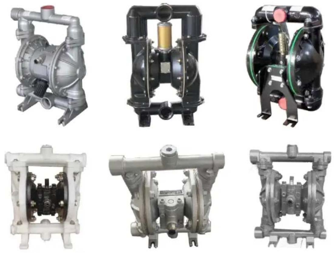
This series of diaphragm pumps are the latest model at home. They are functioned to take out and suck in various corrosive liquid containing granules, viscous, volatile, inflammable, explosive or poisonous liquid, porcelain slurry, mashed fruit, flue. The reclamation of residual oil in tanker. temporary reversion of tanker, etc. The performance parameters of this series are close to that of German WILDEN PUMPS and American MARIO-W PUMPS. The components in contact with flow are made of stainless steel, aluminium alloy, cast iron and engineering plastics, while diaphragm may be NBR, Viton, neoprene or PTFE.
MAIN APPLICATION
- The pump can handle peanuts, pickles, tomatoes, slurry, red sausages, chocolate, hops, and syrup, etc.
- The pump can handle paint, pigments, glue, and adhesives, etc.;
- The pump can handle various glazed slurries of tile, porcelain, brick, and chinaware, etc.
- The pump can handle various grinding materials, corrosive agents, and oil dirt, etc.
- The pump can handle various toxic, flammable, or volatile liquids.
- The pump can handle various muddy water, cement slurry, and mortar.
- The pump can handle various strong acids, alkalis, and corrosive liquids, etc.
- It can be used as a front-step transmission device for solid-liquid separation equipment.
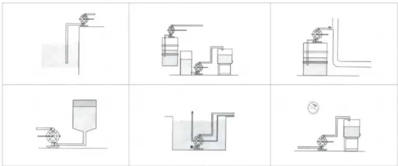
INSTALLATION METHOD
PERFORMANCE CHARACTERISTICS
Air-operated double diaphragm pumps can not only discharge flowing liquids but also convey some difficult-to-flow media, with the advantages of self-priming pumps, submersible pumps, shield pumps, slurry pumps, and impurity pumps, etc.
- It is unnecessary to pour priming water; the suction lift reaches 7 meters, the delivery lift reaches 50 meters, and the outlet pressure is >6 kgf/cm².
- Wide flow and good performance. The diameter of particles allowed to pass reaches 10 mm. The damage to the pump is very minimal when handling slurry and impurities.
- The delivery life and flow can be adjusted steplessly by opening the pneumatic valve (the pneumatic pressure adjustment is between 2-8 kgf/cm²).
- This pump has no rotating parts and no bearing seals. The diaphragm completely separates the exhausted medium from the pump's running parts and working medium. The conveyed medium cannot leak outside. Thus, it will not cause environmental pollution or endanger human safety while exhausting toxic, flammable, or corrosive media.
- No electricity. It is safe and reliable to use in flammable and explosive places.
- It can be soaked in the medium.
- It is convenient to use and reliable to work. Only open or close the valve body when starting or stopping. Even if it operates without medium or pauses suddenly for a long time due to accidents, the pump will not be damaged by this. Once overloaded, the pump will automatically stop and possess self-protection function. When the load recovers normally, it can also start automatically.
8. Simple structure and few wearing parts. This pump is simple in structure, installation, and maintenance. The medium conveyed by the pump will not touch the matched pneumatic valve and coupling lever, etc., unlike other kinds of pumps. The performance will drop down gradually because of the damages of rotor, gear, and vane, etc.
- It can transmit adhesive (viscosity below 10000 centipoise).
- This pump does not need oil lubrication. Even if idling, it has no influence on the pump. This is a characteristic of this pump.
OPERATIONAL PRINCIPLE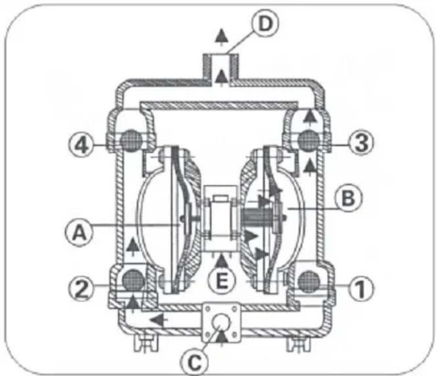
Each diaphragm is installed in both aligned working cavities (A) and (B), which can be connected together with a central coupling lever. The compressed air enters the air distribution valve from the air inlet of the pump, then enters the cavity through the air distribution mechanism, pushing the diaphragm to move in the cavity. The gas in the other cavity will be drained. Once reaching the stroke end, the air distribution mechanism will automatically draw the compressed air into the other working cavity, pushing the diaphragm to move in the opposite direction, so that both diaphragms continuously reciprocate in synchronism.
The compressed air enters the air distribution valve from (E) as shown in the diagram, causing the diaphragm to move to the right. The suction force in chamber (A) lets the medium flow in from inlet (C), pushing the ball valve (2) to open and enter chamber (A), while ball valve (4) is closed due to the suction force. The medium in chamber (B) is pressed out through ball valve (3) and flows out from the outlet (D). Meanwhile, valve (I) is closed to prevent backflow. This cyclic movement allows the medium to be continuously sucked from inlet (C) and discharged from outlet (D).
CONNECTION SCHEMATIC DIAGRAM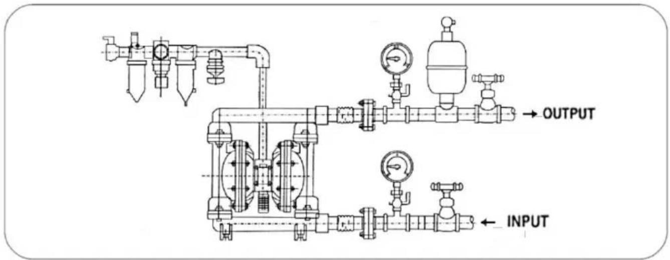
Note: Affected by the stability of gas supply and the environment, the parameters may have certain fluctuations or errors, which is a normal phenomenon.
| Model | Cmax(GPM) | Hmax(m) | pressuse(kgf/cm2) | suckedlift(m) | Max grainDia(mm) | Max pressure(kgf/cm2) | MWP(pSI) | Air inletSize | Inlet andoutlet size |
| 08K-40L | 44 | 69 | 6.9 | 5 | 4.5 | 7 | 115 | 1.5" | |
| 08Y4-50L | 75 | 75 | 8.0 | 7 | 8.0 | 8 | 113 | FNPT 1/4" | 2.0" |
| 08Y4-25L | 22 | 73 | 8.0 | 7 | 4.0 | 8 | 100 | FNPT 1/4" | 1.0" |
| 08Y4-25LF46 | 24 | 70 | 8.0 | 7 | 4.0 | 8 | 100 | FNPT 1/4" | 1.0" |
| 08Y-15PP | 2.5 | 50 | 6.0 | 5 | 1.0 | 7 | 80 | FNPT 1/4" | 1/2" |
| 08K-15P | 3 | 60 | 6.9 | 5 | 1.0 | 7 | 90 | FNPT 1/4" | 1/2" |
| 08K-15 | 3 | 60 | 6.9 | 5 | 1.0 | 7 | 90 | FNPT 1/4" | 1/2" |
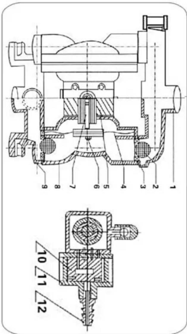
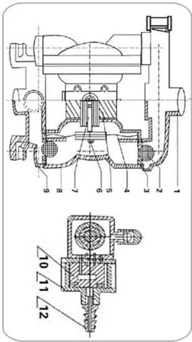
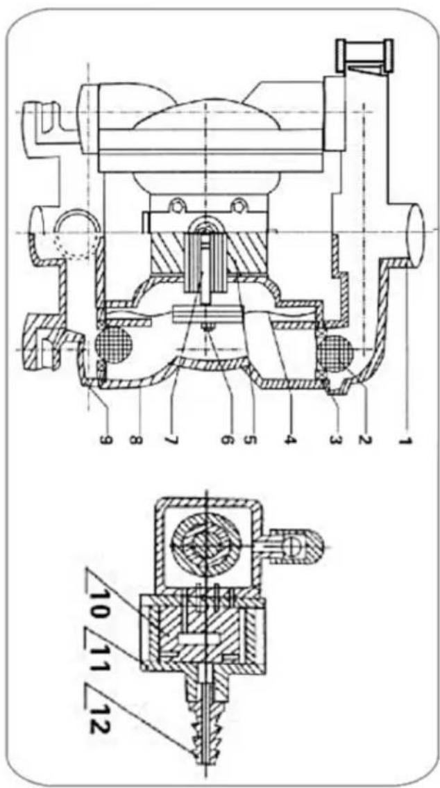
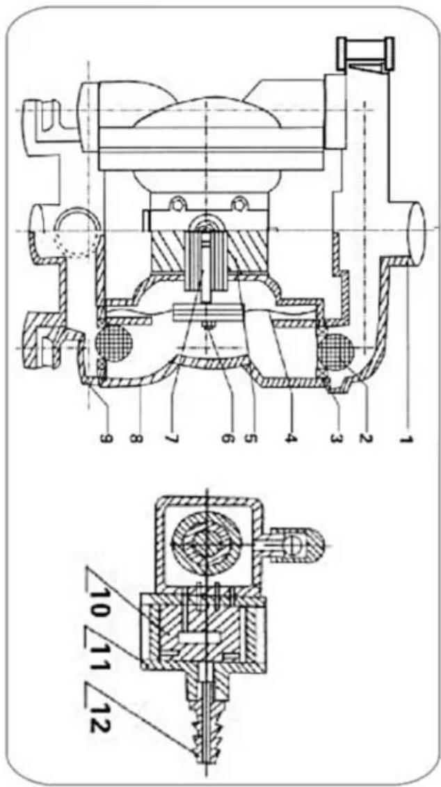
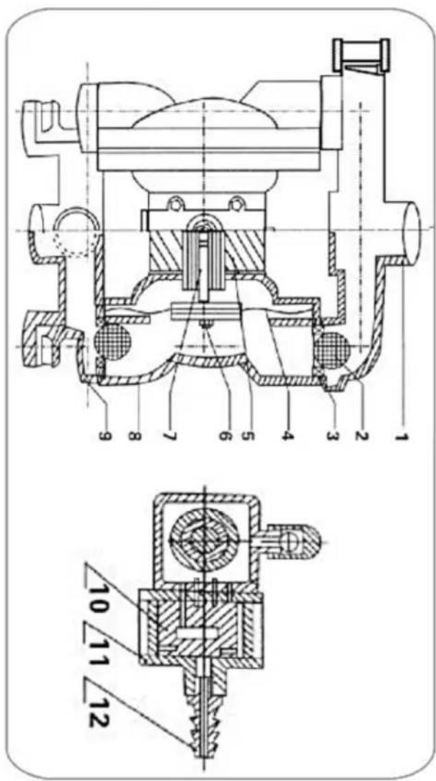
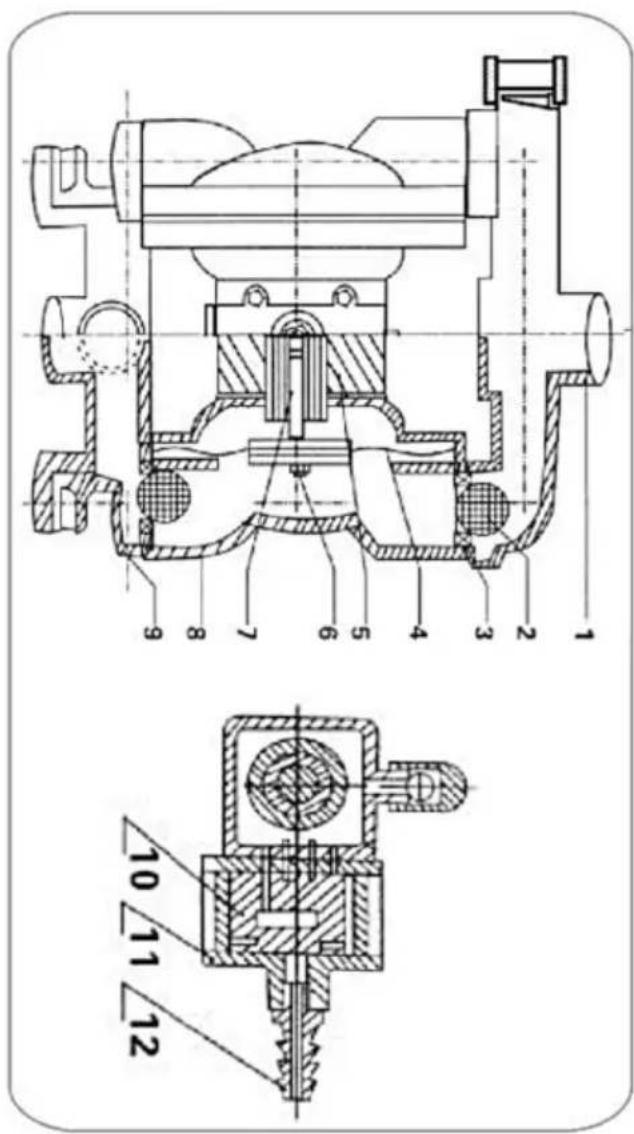
| QBY-10 Structural drawing | |
| 01.Outlet pipe | 02.Ball sealer |
| 03.Seal seat | 04.Diaphragm vane |
| 05.Intermediate | 06.Connecting components |
| 07.Copperroads | 08.Pump body |
| 09.Inlet pipe | 10.Valve pluy |
| 12.Admilion piece | 13.Air distribution valve |
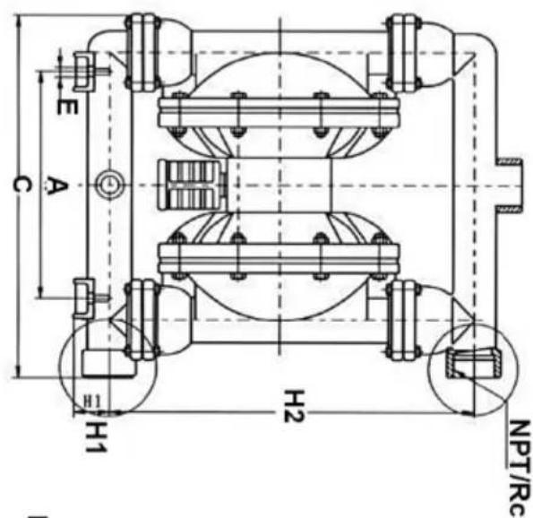
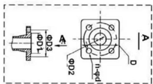
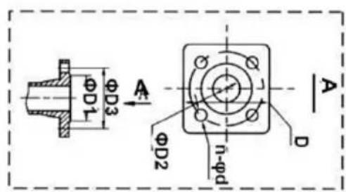
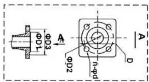
FLANGE CONNECTION TYPE
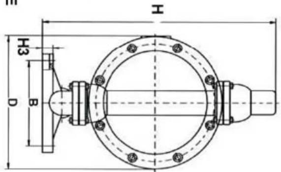
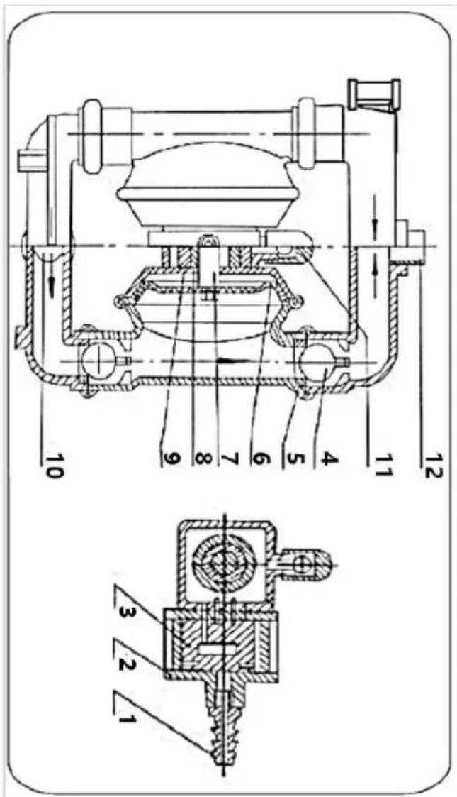
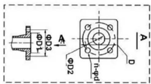
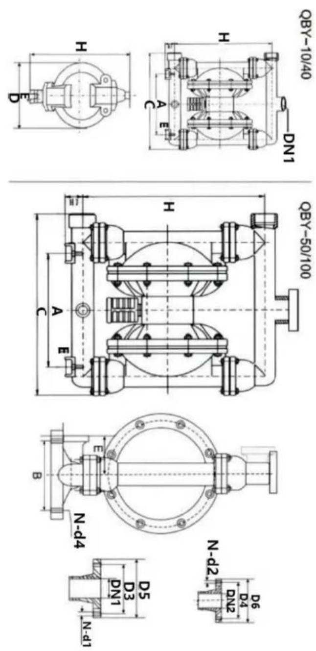
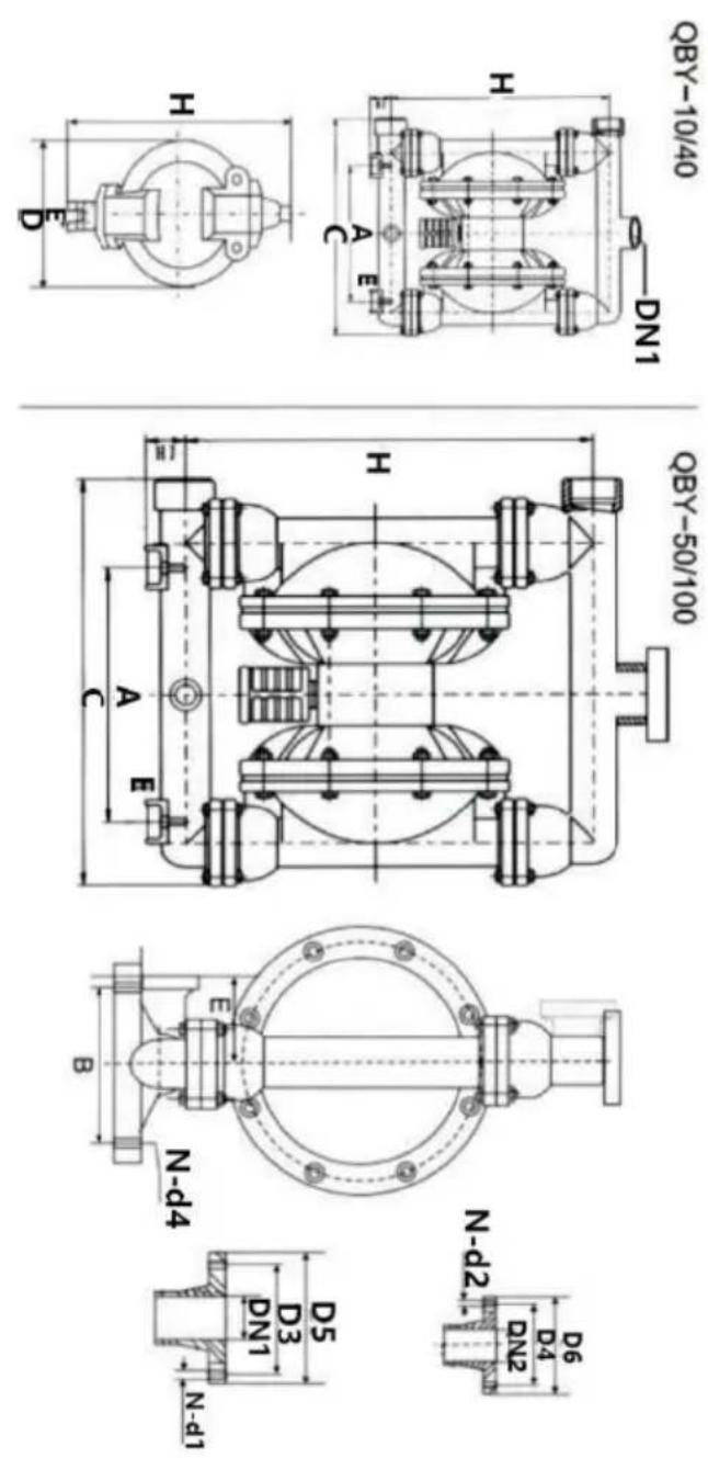
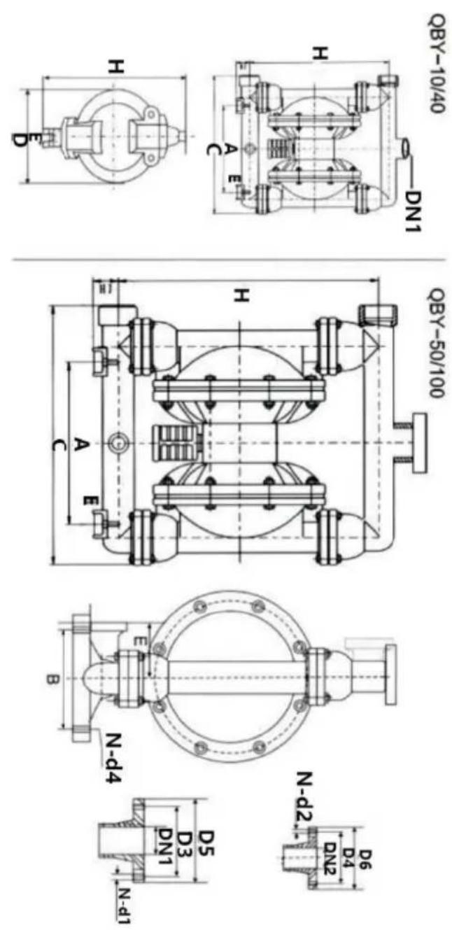
| QBY-50~100 Structural drawing | |
| 01. Admi Ion piece | 02. Air distribution valve |
| 03. Air distribution valve | 04.Bail sealor |
| 05. Seal seal | 06. Diaphragm vane |
| 07. Connecting components | 08. Copper roads |
| 09. Intermediate | 10. Inft pipe |
| 11. Air outlet | 12. Outlet pipe |
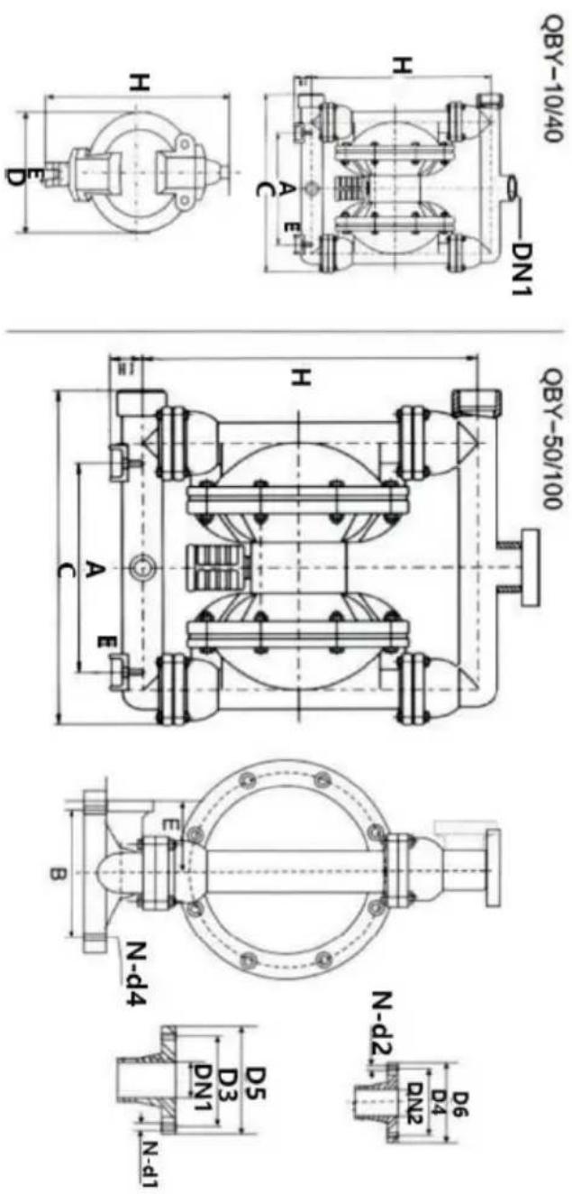
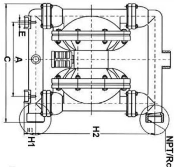
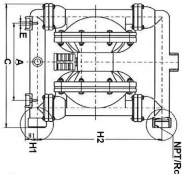
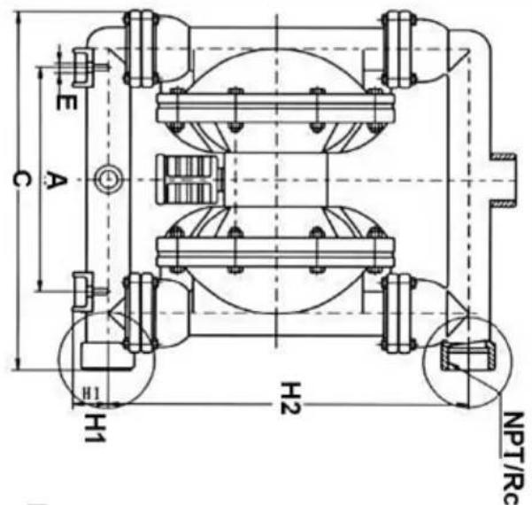
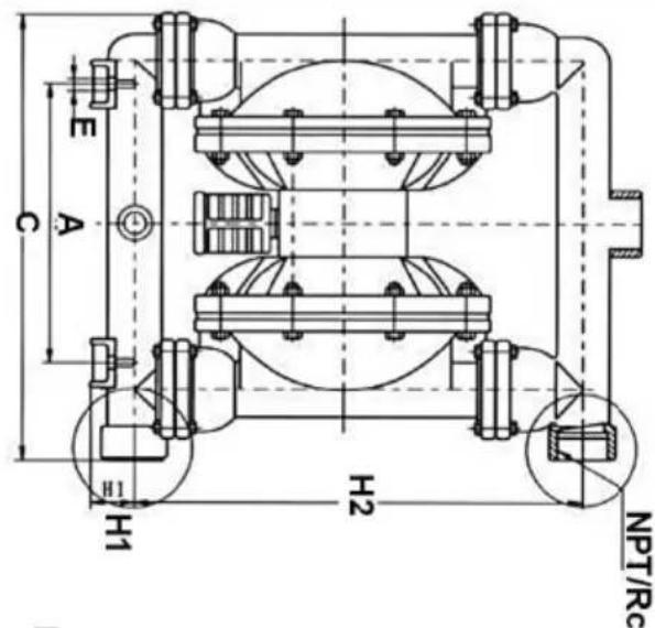
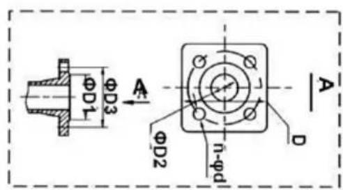
| Model | A | B | D5 | D6 | C | H | H1 | H2 | DHI | DN2 | N-D1 | N-D2 | D3 | D4 | E | N-d4 | Outside diameter or ink† | Materials |
| OBY-10 (ZL104) (ICR18N9TI) (pp) | 53 | / | 190 | 235 | 35 | 220 | 3/8"Threaded | / | / | / | / | / | 12 | / | 8 | (HT200) | ||
| OBY-15 | 135 | 53 | / | 190 | 235 | 35 | 220 | 1/2"Threaded | / | / | / | / | / | 12 | / | 8 | ||
| OBY-25 | 255 | 150 | 100 | 380 | 530 | 70 | 1"Threaded | 4-Φ11 | 4-Φ11 | 75 | 75 | 55 | 4-Φ10 | 10 | (PP) Impacts and exports are facing the edge | |||
| OBY-40 | 255 | 150 | 130 | 120 | 380 | 530 | 70 | 11/2"Threaded | 4-Φ13.5 | 4-Φ13.5 | 100 | 90 | 55 | 4-Φ10 | 10 | |||
| OBY-25 | 220 | 160 | 100 | 100 | 370 | 460 | 50 | 410 | 1"Threaded | 4-Φ11 | 4-Φ11 | 75 | 75 | 80 | 4-Φ12 | 10 | ||
| OBY-40 | 220 | 160 | 130 | 120 | 370 | 460 | 410 | 11/2"Threaded | 4-Φ13.5 | 4-Φ13.5 | 100 | 90 | 4-Φ12 | 10 | ||||
| OBY-50 | 340 | 215 | 140 | 140 | 550 | 715 | 95 | 2"Range | 4-Φ13.5 | 4-Φ13.5 | 110 | 110 | 145 | 4-Φ17.5 | 12 | |||
| OBY-65 | 340 | 215 | 160 | 140 | 550 | 715 | 95 | 21⁄2"Range | 4-Φ13.5 | 4-Φ13.5 | 130 | 130 | 145 | 4-Φ17.5 | 12 | |||
| OBY-80 | 360 | 260 | 190 | 190 | 580 | 950 | 100 | 3"Range | 4-Φ17.5 | 4-Φ17.5 | 150 | 150 | 130 | 4-Φ17.5 | 12 | |||
| OBY-100 | 360 | 260 | 210 | 190 | 580 | 950 | 100 | 4"Range | 3"Range | 4-Φ17.5 | 4-Φ17.5 | 170 | 170 | 130 | 4-Φ17.5 | 12 |
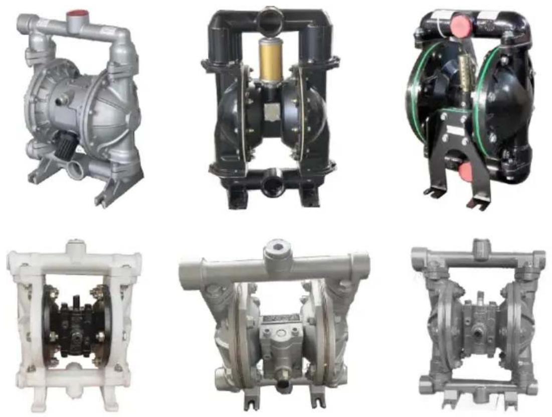
Note: QBY-10 and 15 cast iron/aluminum/stainless steel/plastic material import and export are threaded connections, not flanged. QBY-25 and 40 stainless steel/plastic material import and export are threaded connections, not flanged, while cast iron/aluminum alloy import and export are flanged, and threaded connections are dual-use. QBY-50/65/80/100 are flanged, no threaded. (Please refer to the actual sample product catalog pictures)
STRUCTURE DRAWING AND PARTS LIST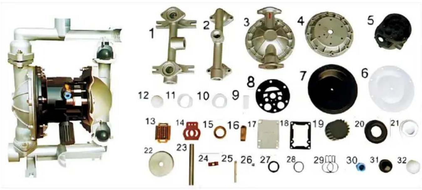
| No. | Name | Qty | Material |
| 1 | Inlet pipe | 1 | Stainless steel, cast iron, aluminium alloy, plastic, inner lining FEP |
| 2 | Outlet pipe | 1 | Stainless steel, cast iron, aluminium alloy, plastic, inner lining FEP |
| 3 | Pump body | 2 | Stainless steel, cast iron, aluminium alloy, plastic, inner lining FEP |
| 4 | Pump chamber | 2 | Aluminium alloy, cast iron |
| 5 | Intermediate | 1 | Aluminium alloy |
| 6 | Diaphragm vane | 2 | PTFE |
| 7 | Diaphragm vane | 2 | Acrylonitrile butadiene rubber, polychloroprene |
| 8 | ntermediate sealgasket | 2 | Acrylonitrile butadiene rubber |
| 9 | Driving shaft housing | 2 | Plastic |
| 10 | Connecting rod shaft housing | 2 | Plastic |
| 11 | Piston bush | 2 | Plastic |
| 12 | Piston | 2 | Plastic |
| 13 | Slipper block | 1 | Aluminium alloy |
| 14 | Slipper block | 1 | Chromium-plated steel |
| 15 | Sealing slip ring | 1 | Plastic |
| 16 | Driving slipper block | 1 | Plastic |
| 17 | Cover plate | 1 | Aluminium alloy |
| 18 | Cover plate gasket | 1 | Rubber |
| 19 | Muffler | 1 | Plastic |
| 20 | Seal seat | 4 | Rubber |
| 21 | Seal seat | 4 | PTFE |
| 22 | Clamping bar | 4 | Stainless steel, carbon steel |
| 23 | Connecting rod | 1 | Stainless steel |
| 24 | Compression spring | 1 | Copper |
| 25 | Driving shaft | 1 | Stainless steel |
| 26 | Seal ring of driving shaft | 2 | Rubber |
| 27 | Y-type O-ring | 4 | Rubber |
| 28 | O-ring | 1 | Rubber |
| 29 | Butterfly-type O-ring | 1 | Rubber |
| 30 | Inlet nozzle | 1 | Copper |
| 31 | Ball sealer | 4 | Rubber |
| 32 | Ball sealer | 4 | Stainless steel, ceramic, PTFE |
MATTERS NEED ATTENTION
- If the pump vibration is very slight, there is generally no need to install foundation bolts. 2. If the compressed air is mixed with dirty things, normal starting of the pump will be influenced. It is suggested that users should additionally install the pneumatic triplex parts.
- When pumping media that will easily freeze or deposit, please install a valve at the inlet of the pump. If the pump is to be stopped, please firstly close the valve, and then run the pump for several minutes to empty the media inside the pump and clean accumulated liquid inside the pump in time, so as to avoid any difficulties in starting the pump next time.
- When replacing the diaphragm, please clean the connecting rod, the inner cavity, and the copper bush of the pump. And avoid damaging the white PTFE seal ring. Make the reassembly as original, and the pump can be used.
| Malfunction forms | Causes | Troubleshooting |
| No water comes out from the pump or the flow is insufficient. | 1、The air pressure is insufficient.2、The flow channel of the pump cavity is blocked3、The valve is not opened | 1、Add the air pressure 2、Open the pump cavity for cleaning 3、Open the valve |
| The pump stops its operation | 1、The air distribution valve is damaged2、The diaphragm is damaged3、The muffler is blocked4、Air leakage occurs in the conn-eciting rod seal | 1、Repair or replace the air distribution valve2、Replace the diaphragm3、Clean the muffler.4、Replace the connecting rod seal |
| The lift is too low | 1、The suction valve is damaged2、The flow is too high3、The air pressure is too low | 1、Shotten the pipe and reduce elbows2、Turn down the drain valve.3、Add the air pressure |
| The noise is too low | 1、The muffler is broken | 1、Add the air pressure. |
Made In China
VEVOR®
TOUGH TOOLS, HALF PRICE
Technical Support and E-Warranty Certificate
www.vevor.com/support
VEVOR®
TOUGH TOOLS, HALF PRICE
We continue to be committed to providing you tools with competitive prices. "Save Half", "Half Price", or any other similar expressions used by us only represent the savings you might benefit from buying certain tools with us compared to top brands, and does not necessarily mean to cover all categories of tools offered. We kindly remind you to verify carefully when placing an order with us that you are actually saving half in comparison with the top major brands.
VEVOR®
TOUGH TOOLS, HALF PRICE
Air Operated Double
Diaphragm Pump
MODEL: QBK-40L/QBY4-50L/QBY4-25L/QBY4-25LF46 /
QBY-15PP/QBK-15P/QBK-15
NEED HELP? CONTACT US!
Have product questions? Need technical support? Please feel free to contact us:
Technical Support and E-Warranty Certificate
www.vevor.com/support
This is the original instruction. Please read all manual instructions carefully before operating. VEVOR reserves a clear interpretation of the user manual. The appearance of the product shall be subject to the product you received. Please forgive us that we won't inform you if there are any technology or software updates on our product.

PRODUCT PRESENTATION
PERFORMANCE CHARACTERISTICS
Note: Affected by the stability of gas supply and the environment, the parameters may have certain fluctuations or errors, which is a normal phenomenon.
| Model | Cmax(GPM) | Hmax(m) | pressuse(kgf/cm2) | suckedlift(m) | MaxgainDia(pms)(kgf/cm2) | MWP(pSI) | Air InletSIZE |
| OBR-40L | 44 | 69 | 6.9 | 5 | 4.5 | 115 | |
| OBRY4-50L | 75 | 75 | 8.0 | 7 | 8.0 | 8 | 113 |
| OBRY4-25L | 22 | 73 | 8.0 | 7 | 4.0 | 8 | 100 |
| OBRY4-25LF46 | 24 | 70 | 8.0 | 7 | 4.0 | 8 | 100 |
| OBRY-15PP | 2.5 | 50 | 6.0 | 5 | 1.0 | 7 | 80 |
| OBRK-15P | 3 | 60 | 6.9 | 5 | 1.0 | 7 | 90 |
| OBRK-15 | 3 | 60 | 6.9 | 5 | 1.0 | 7 | 90 |
QBK INSTALLATION SIZE CHART
| QBY-10Structural drawing | |
| 01. Outlet pipe | 02. Ball sealer |
| 03. Seal seat | 04. Diaphragm vane |
| 05. Intermediate | 06. Connecting components |
| 07. Copperroads | 08. Pump body |
| 09. Inlet pipe | 10. Valve play |
| 12. Admi Ion piece | 13. Air distribution valve |
FLANGE CONNECTION TYPE
| GBY-50~100 Structural drawing | |
| 01. Admi Ion piece | 02. Air distribution valve |
| 03. Air distribution valve | 04.Bail sealar |
| 05. Seal seal | 06. Diaphragm vane |
| 07. Connecting components | 08. Copper roads |
| 09. Intermediate | 10. Inft pipe |
| 11. Air outlet | 12. Outlet pipe |
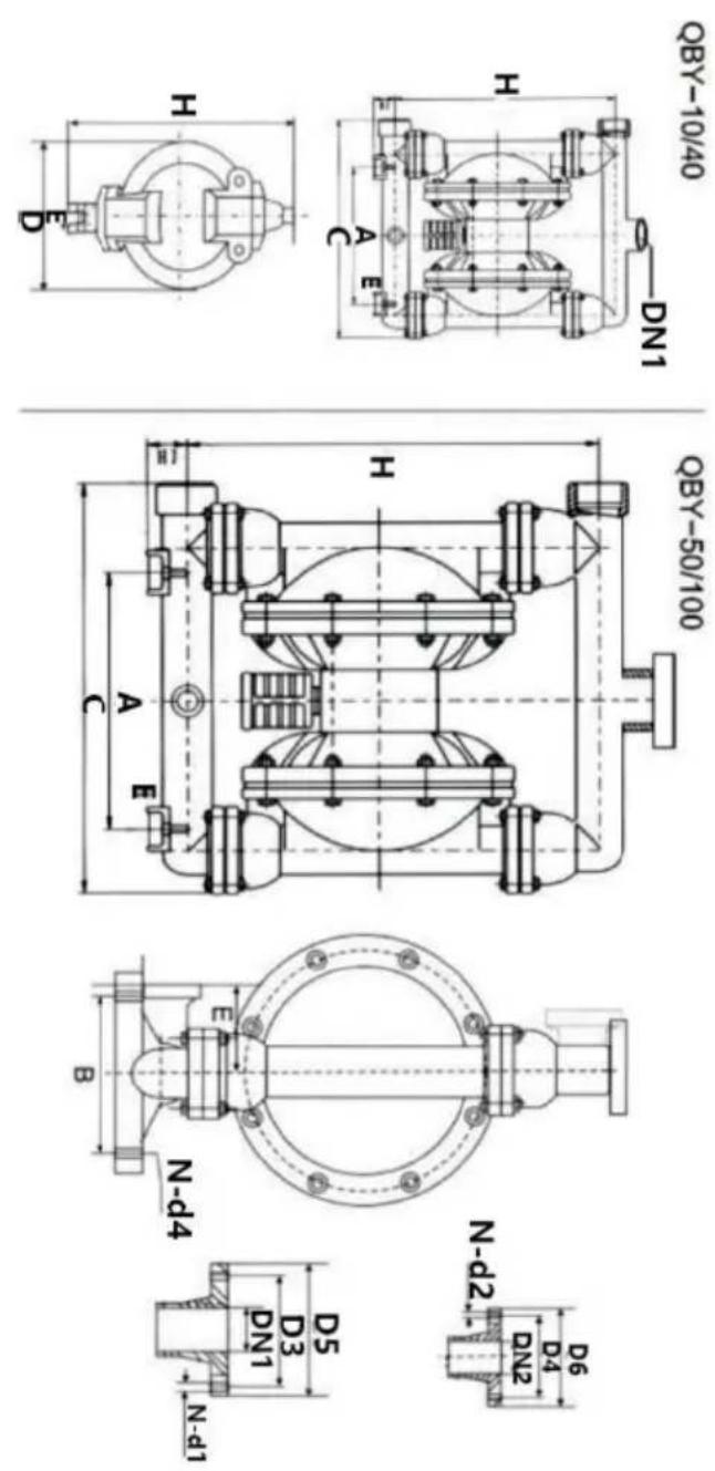
| Model | A | B | D5 | D6 | C | H | H1 | H2 | DHI | DN2 | N-D1 | N-D2 | D3 | D4 | E | N-d4 | Outside diameter or ink† | Materials |
| OBY-10 (ZL104) (ICR18N9TI) (pp) | 53 | / | 190 | 235 | 35 | 220 | 3/8"Threaded | / | / | / | / | / | 12 | / | 8 | (HT200) | ||
| OBY-15 | 135 | 53 | / | 190 | 235 | 35 | 220 | 1/2"Threaded | / | / | / | / | / | 12 | / | 8 | ||
| OBY-25 | 255 | 150 | 100 | 380 | 530 | 70 | 1"Threaded | 4-Φ11 | 4-Φ11 | 75 | 75 | 55 | 4-Φ10 | 10 | (PP) Impacts and exports are facing the edge | |||
| OBY-40 | 255 | 150 | 130 | 120 | 380 | 530 | 70 | 11/2"Threaded | 4-Φ13.5 | 4-Φ13.5 | 100 | 90 | 55 | 4-Φ10 | 10 | |||
| OBY-25 | 220 | 160 | 100 | 100 | 370 | 460 | 50 | 410 | 1"Threaded | 4-Φ11 | 4-Φ11 | 75 | 75 | 80 | 4-Φ12 | 10 | ||
| OBY-40 | 220 | 160 | 130 | 120 | 370 | 460 | 410 | 11/2"Threaded | 4-Φ13.5 | 4-Φ13.5 | 100 | 90 | 4-Φ12 | 10 | ||||
| OBY-50 | 340 | 215 | 140 | 140 | 550 | 715 | 95 | 2"Range | 4-Φ13.5 | 4-Φ13.5 | 110 | 110 | 145 | 4-Φ17.5 | 12 | |||
| OBY-65 | 340 | 215 | 160 | 140 | 550 | 715 | 95 | 21⁄2"Range | 4-Φ13.5 | 4-Φ13.5 | 130 | 130 | 145 | 4-Φ17.5 | 12 | |||
| OBY-80 | 360 | 260 | 190 | 190 | 580 | 950 | 100 | 3"Range | 4-Φ17.5 | 4-Φ17.5 | 150 | 150 | 130 | 4-Φ17.5 | 12 | |||
| OBY-100 | 360 | 260 | 210 | 190 | 580 | 950 | 100 | 4"Range | 3"Range | 4-Φ17.5 | 4-Φ17.5 | 170 | 170 | 130 | 4-Φ17.5 | 12 |
STRUCTURE DRAWING AND PARTS LIST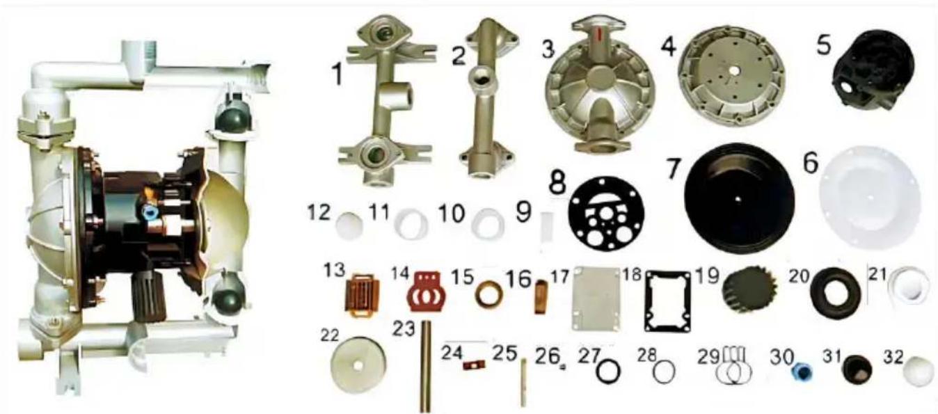
| No. | Name | Qty | Material |
| 1 | Inlet pipe | 1 | Stainless steel, cast iron, aluminium alloy, plastic, inner lining FEP |
| 2 | Outlet pipe | 1 | Stainless steel, cast iron, aluminium alloy, plastic, inner lining FEP |
| 3 | Pump body | 2 | Stainless steel, cast iron, aluminium alloy, plastic, inner lining FEP |
| 4 | Pump chamber | 2 | Aluminium alloy, cast iron |
| 5 | Intermediate | 1 | Aluminium alloy |
| 6 | Diaphragm vane | 2 | PTFE |
| 7 | Diaphragm vane | 2 | Acrylonitrile butadiene rubber, polychloroprene |
| 8 | ntermediate sealgasket | 2 | Acrylonitrile butadiene rubber |
| 9 | Driving shaft housing | 2 | Plastic |
| 10 | Connecting rod shaft housing | 2 | Plastic |
| 11 | Piston bush | 2 | Plastic |
| 12 | Piston | 2 | Plastic |
| 13 | Slipper block | 1 | Aluminium alloy |
| 14 | Slipper block | 1 | Chromium-plated steel |
| 15 | Sealing slip ring | 1 | Plastic |
| 16 | Driving slipper block | 1 | Plastic |
| 17 | Cover plate | 1 | Aluminium alloy |
| 18 | Cover plate gasket | 1 | Rubber |
| 19 | Muffler | 1 | Plastic |
| 20 | Seal seat | 4 | Rubber |
| 21 | Seal seat | 4 | PTFE |
| 22 | Clamping bar | 4 | Stainless steel, carbon steel |
| 23 | Connecting rod | 1 | Stainless steel |
| 24 | Compression spring | 1 | Copper |
| 25 | Driving shaft | 1 | Stainless steel |
| 26 | Seal ring of driving shaft | 2 | Rubber |
| 27 | Y-type O-ring | 4 | Rubber |
| 28 | O-ring | 1 | Rubber |
| 29 | Butterfly-type O-ring | 1 | Rubber |
| 30 | Inlet nozzle | 1 | Copper |
| 31 | Ball sealer | 4 | Rubber |
| 32 | Ball sealer | 4 | Stainless steel, ceramic, PTFE |
MATTERS NEED ATTENTION
| Malfunction forms | Causes | Troubleshooting |
| No water comes out from the pump or the flow is insufficient. | 1、The air pressure is insufficient.2、The flow channel of the pump cavity is blocked3、The valve is not opened | 1、Add the air pressure 2、Open the pump cavity for cleaning 3、Open the valve |
| The pump stops its operation | 1、The air distribution valve is damaged2、The diaphragm is damaged3、The muffler is blocked4、Air leakage occurs in the conn-eciting rod seal | 1、Repair or replace the air distribution valve2、Replace the diaphragm3、Clean the muffler.4、Replace the connecting rod seal |
| The lift is too low | 1、The suction valve is damaged2、The flow is too high3、The air pressure is too low | 1、Shotten the pipe and reduce elbows2、Turn down the drain valve.3、Add the air pressure |
| The noise is too low | 1、The muffler is broken | 1、Add the air pressure. |
Made in China
VEVOR®
TOUGH TOOLS, HALF PRICE
We continue to be committed to provide you tools with competitive price. "Save Half", "Half Price" or any other similar expressions used by us only represent estimate of savings you might benefit from buying certain tools with us compared to top brands and does not necessarily mean to cover all categories of tools offered are kindly reminded to verify carefully when you are placing an order with us actually saving half in comparison with the top major brands.
VEVOR®
TOUGH TOOLS, HALF PRICE
Air Operated Double Diaphragm Pump
MODELL: QBK-40L/QBY4-50L/QBY4-25L/QBY4-25LF46 / QBY-15PP/QBK-15P/QBK-15
NEED HELP? CONTACT US!
Have product questions? Need technical support? Please feel free to contact us:
Technical Support and E-Warranty Certificate www.vevor.com/support
This is the original instruction. Please read all manual instructions carefully before operating. VEVOR reserves a clear interpretation of the user manual. The appearance of the product shall be subject to the product you received. Please forgive us that we won't inform you if there are any technology or software updates on our product.
PRODUCT PRESENTATION
PERFORMANCE CHARACTERISTICS
Note: Affected by the stability of gas supply and the environment, the parameters may have certain fluctuations or errors, which is a normal phenomenon.
| Model | Cmax(GPM) | Hmax(m) | pressuse(kgf/cm2) | suckedlift(m) | MaxgainDia(kgf/cm2) | Max pressure(pSI) | MWP | Pump |
| (6PM) | (perssuse(m) | (kgf/cm2) | (Dia(mm)) | (kgf/cm2) | ||||
| OBR-40L | 44 | 69 | 6.9 | 5 | 4.5 | 7 | 115 | 1.5" |
| OBR4-50L | 75 | 75 | 8.0 | 7 | 8.0 | 8 | 113 | 2.0" |
| OBR4-25L | 22 | 73 | 8.0 | 7 | 4.0 | 8 | 100 | 1.0" |
| OBRY4-25LF46 | 24 | 70 | 8.0 | 7 | 4.0 | 8 | 100 | 1.0" |
| OBRY-15PP | 2.5 | 50 | 6.0 | 5 | 1.0 | 7 | 80 | 1/2" |
| OBR-15P | 3 | 60 | 6.9 | 5 | 1.0 | 7 | 90 | 1/2" |
| OBR-15 | 3 | 60 | 6.9 | 5 | 1.0 | 7 | 90 | 1/2" |
QBK INSTALLATION SIZE CHART
| QBY-10Structural drawing | |
| 01. Outlet pipe | 02. Ball sealer |
| 03. Seal seat | 04. Diaphragm vane |
| 05. Intermediate | 06. Connecting components |
| 07. Copperroads | 08. Pump body |
| 09. Inlet pipe | 10. Valve play |
| 12. Admi Ion piece | 13. Air distribution valve |
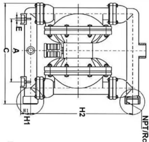
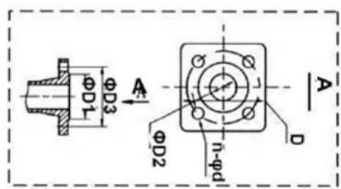
FLANGE CONNECTION TYPE
| GBY-50~100 Structural drawing | |
| 01. Admi Ion piece | 02. Air distribution valve |
| 03. Air distribution valve | 04.Bail sealar |
| 05. Seal seal | 06. Diaphragm vane |
| 07. Connecting components | 08. Copper roads |
| 09. Intermediate | 10. Inft pipe |
| 11. Air outlet | 12. Outlet pipe |
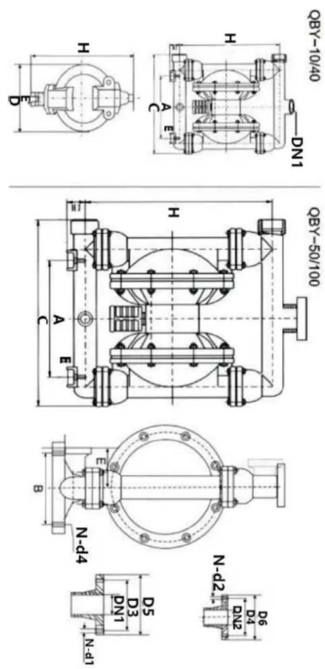
| Model | A | B | D5 | D6 | C | H | H1 | H2 | DHI | DN2 | N-D1 | N-D2 | D3 | D4 | E | N-d4 | Outside diameter or ink† | Materials |
| OBY-10 (ZL104) (ICR18N9TI) (pp) | 53 | / | 190 | 235 | 35 | 220 | 3/8"Threaded | / | / | / | / | / | 12 | / | 8 | (HT200) | ||
| OBY-15 | 135 | 53 | / | 190 | 235 | 35 | 220 | 1/2"Threaded | / | / | / | / | / | 12 | / | 8 | ||
| OBY-25 | 255 | 150 | 100 | 380 | 530 | 70 | 1"Threaded | 4-Φ11 | 4-Φ11 | 75 | 75 | 55 | 4-Φ10 | 10 | (PP) Impacts and exports are facing the edge | |||
| OBY-40 | 255 | 150 | 130 | 120 | 380 | 530 | 70 | 11/2"Threaded | 4-Φ13.5 | 4-Φ13.5 | 100 | 90 | 55 | 4-Φ10 | 10 | |||
| OBY-25 | 220 | 160 | 100 | 100 | 370 | 460 | 50 | 410 | 1"Threaded | 4-Φ11 | 4-Φ11 | 75 | 75 | 80 | 4-Φ12 | 10 | ||
| OBY-40 | 220 | 160 | 130 | 120 | 370 | 460 | 410 | 11/2"Threaded | 4-Φ13.5 | 4-Φ13.5 | 100 | 90 | 4-Φ12 | 10 | ||||
| OBY-50 | 340 | 215 | 140 | 140 | 550 | 715 | 95 | 2"Range | 4-Φ13.5 | 4-Φ13.5 | 110 | 110 | 145 | 4-Φ17.5 | 12 | |||
| OBY-65 | 340 | 215 | 160 | 140 | 550 | 715 | 95 | 21⁄2"Range | 4-Φ13.5 | 4-Φ13.5 | 130 | 130 | 145 | 4-Φ17.5 | 12 | |||
| OBY-80 | 360 | 260 | 190 | 190 | 580 | 950 | 100 | 3"Range | 4-Φ17.5 | 4-Φ17.5 | 150 | 150 | 130 | 4-Φ17.5 | 12 | |||
| OBY-100 | 360 | 260 | 210 | 190 | 580 | 950 | 100 | 4"Range | 3"Range | 4-Φ17.5 | 4-Φ17.5 | 170 | 170 | 130 | 4-Φ17.5 | 12 |
STRUCTURE DRAWING AND PARTS LIST
| No. | Name | Qty | Material |
| 1 | Inlet pipe | 1 | Stainless steel, cast iron, aluminium alloy, plastic, inner lining FEP |
| 2 | Outlet pipe | 1 | Stainless steel, cast iron, aluminium alloy, plastic, inner lining FEP |
| 3 | Pump body | 2 | Stainless steel, cast iron, aluminium alloy, plastic, inner lining FEP |
| 4 | Pump chamber | 2 | Aluminium alloy, cast iron |
| 5 | Intermediate | 1 | Aluminium alloy |
| 6 | Diaphragm vane | 2 | PTFE |
| 7 | Diaphragm vane | 2 | Acrylonitrile butadiene rubber, polychloroprene |
| 8 | ntermediate sealgasket | 2 | Acrylonitrile butadiene rubber |
| 9 | Driving shaft housing | 2 | Plastic |
| 10 | Connecting rod shaft housing | 2 | Plastic |
| 11 | Piston bush | 2 | Plastic |
| 12 | Piston | 2 | Plastic |
| 13 | Slipper block | 1 | Aluminium alloy |
| 14 | Slipper block | 1 | Chromium-plated steel |
| 15 | Sealing slip ring | 1 | Plastic |
| 16 | Driving slipper block | 1 | Plastic |
| 17 | Cover plate | 1 | Aluminium alloy |
| 18 | Cover plate gasket | 1 | Rubber |
| 19 | Muffler | 1 | Plastic |
| 20 | Seal seat | 4 | Rubber |
| 21 | Seal seat | 4 | PTFE |
| 22 | Clamping bar | 4 | Stainless steel, carbon steel |
| 23 | Connecting rod | 1 | Stainless steel |
| 24 | Compression spring | 1 | Copper |
| 25 | Driving shaft | 1 | Stainless steel |
| 26 | Seal ring of driving shaft | 2 | Rubber |
| 27 | Y-type O-ring | 4 | Rubber |
| 28 | O-ring | 1 | Rubber |
| 29 | Butterfly-type O-ring | 1 | Rubber |
| 30 | Inlet nozzle | 1 | Copper |
| 31 | Ball sealer | 4 | Rubber |
| 32 | Ball sealer | 4 | Stainless steel, ceramic, PTFE |
MATTERS NEED ATTENTION
| Malfunction forms | Causes | Troubleshooting |
| No water comes out from the pump or the flow is insufficient. | 1、The air pressure is insufficient.2、The flow channel of the pump cavity is blocked3、The valve is not opened | 1、Add the air pressure 2、Open the pump cavity for cleaning 3、Open the valve |
| The pump stops its operation | 1、The air distribution valve is damaged2、The diaphragm is damaged3、The muffler is blocked4、Air leakage occurs in the conn-eciting rod seal | 1、Repair or replace the air distribution valve2、Replace the diaphragm3、Clean the muffler.4、Replace the connecting rod seal |
| The lift is too low | 1、The suction valve is damaged2、The flow is too high3、The air pressure is too low | 1、Shotten the pipe and reduce elbows2、Turn down the drain valve.3、Add the air pressure |
| The noise is too low | 1、The muffler is broken | 1、Add the air pressure. |
www.vevor.com/support
VEVOR®
TOUGH TOOLS, HALF PRICE
We continue to be committed to providing you with tools at competitive prices. "Save Half", "Half Price", or any other similar expressions used by us only represent an estimate of savings you might benefit from buying certain tools with us compared to top brands and does not necessarily mean to cover all categories of tools offered. We kindly remind you to verify carefully when placing an order with us that you are actually saving half in comparison with the top major brands.
VEVOR®
TOUGH TOOLS, HALF PRICE
Air Operated Double
Diaphragm Pump
MODEL: QBK-40L/QBY4-50L/QBY4-25L/QBY4-25LF46 /
QBY-15PP/QBK-15P/QBK-15
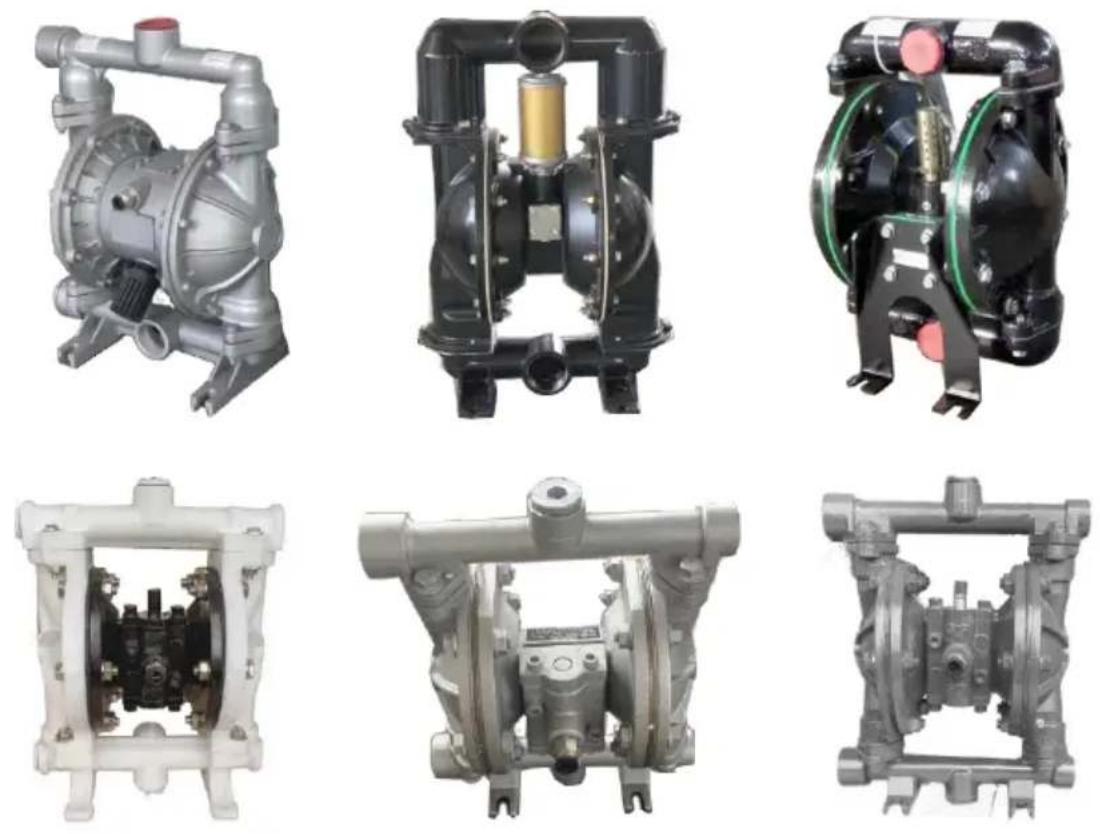
NEED HELP? CONTACT US!
Have product questions? Need technical support? Please feel free to contact us:
Technical Support and E-Warranty Certificate
www.vevor.com/support
This is the original instruction. Please read all manual instructions carefully before operating. VEVOR reserves a clear interpretation of the user manual. The appearance of the product shall be subject to the product you received. Please forgive us that we won't inform you if there are any technology or software updates on our product.

PRODUCT PRESENTATION
PERFORMANCE CHARACTERISTICS
Note: Affected by the stability of gas supply and the environment, the parameters may have certain fluctuations or errors, which is a normal phenomenon.
| Model | Cmax(GPM) | Hmax(m) | pressuse(kgf/cm2) | suckedlift(m) | MaxgainDia(kgf/cm2) | Max pressure(pSI) | MWP | Pump |
| (6PM) | (perssuse(m) | (kgf/cm2) | (Dia(mm)) | (kgf/cm2) | ||||
| OBR-40L | 44 | 69 | 6.9 | 5 | 4.5 | 7 | 115 | 1.5" |
| OBR4-50L | 75 | 75 | 8.0 | 7 | 8.0 | 8 | 113 | 2.0" |
| OBR4-25L | 22 | 73 | 8.0 | 7 | 4.0 | 8 | 100 | 1.0" |
| OBRY4-25LF46 | 24 | 70 | 8.0 | 7 | 4.0 | 8 | 100 | 1.0" |
| OBRY-15PP | 2.5 | 50 | 6.0 | 5 | 1.0 | 7 | 80 | 1/2" |
| OBR-15P | 3 | 60 | 6.9 | 5 | 1.0 | 7 | 90 | 1/2" |
| OBR-15 | 3 | 60 | 6.9 | 5 | 1.0 | 7 | 90 | 1/2" |
QBK INSTALLATION SIZE CHART
| QBY-10Structural drawing | |
| 01. Outlet pipe | 02. Ball sealer |
| 03. Seal seat | 04. Diaphragm vane |
| 05. Intermediate | 06. Connecting components |
| 07. Copperroads | 08. Pump body |
| 09. Inlet pipe | 10. Valve play |
| 12. Admi Ion piece | 13. Air distribution valve |
FLANGE CONNECTION TYPE
| QBY-50~100 Structural drawing | |
| 01. Admi! Ion piece | 02. Air distribution valve |
| 03. Air distribution valve | 04.Ball sealor |
| 05. Seal seal | 06. Diaphragm vane |
| 07. Connecting components | 08. Copper roads |
| 09. Intermediate | 10. Inlt pipe |
| 11. Air outlet | 12. Outlet pipe |
| Model | A | B | D5 | D6 | C | H | H1 | H2 | DHI | DN2 | N-D1 | N-D2 | D3 | D4 | E | N-d4 | Outside diameter or ink† | Materials |
| OBY-10 (ZL104) (ICR18N9TI) (pp) | 53 | / | 190 | 235 | 35 | 220 | 3/8"Threaded | / | / | / | / | / | 12 | / | 8 | (HT200) | ||
| OBY-15 | 135 | 53 | / | 190 | 235 | 35 | 220 | 1/2"Threaded | / | / | / | / | / | 12 | / | 8 | ||
| OBY-25 | 255 | 150 | 100 | 380 | 530 | 70 | 1"Threaded | 4-Φ11 | 4-Φ11 | 75 | 75 | 55 | 4-Φ10 | 10 | (PP) Impacts and exports are facing the edge | |||
| OBY-40 | 255 | 150 | 130 | 120 | 380 | 530 | 70 | 11/2"Threaded | 4-Φ13.5 | 4-Φ13.5 | 100 | 90 | 55 | 4-Φ10 | 10 | |||
| OBY-25 | 220 | 160 | 100 | 100 | 370 | 460 | 50 | 410 | 1"Threaded | 4-Φ11 | 4-Φ11 | 75 | 75 | 80 | 4-Φ12 | 10 | ||
| OBY-40 | 220 | 160 | 130 | 120 | 370 | 460 | 410 | 11/2"Threaded | 4-Φ13.5 | 4-Φ13.5 | 100 | 90 | 4-Φ12 | 10 | ||||
| OBY-50 | 340 | 215 | 140 | 140 | 550 | 715 | 95 | 2"Range | 4-Φ13.5 | 4-Φ13.5 | 110 | 110 | 145 | 4-Φ17.5 | 12 | |||
| OBY-65 | 340 | 215 | 160 | 140 | 550 | 715 | 95 | 21⁄2"Range | 4-Φ13.5 | 4-Φ13.5 | 130 | 130 | 145 | 4-Φ17.5 | 12 | |||
| OBY-80 | 360 | 260 | 190 | 190 | 580 | 950 | 100 | 3"Range | 4-Φ17.5 | 4-Φ17.5 | 150 | 150 | 130 | 4-Φ17.5 | 12 | |||
| OBY-100 | 360 | 260 | 210 | 190 | 580 | 950 | 100 | 4"Range | 3"Range | 4-Φ17.5 | 4-Φ17.5 | 170 | 170 | 130 | 4-Φ17.5 | 12 |
STRUCTURE DRAWING AND PARTS LIST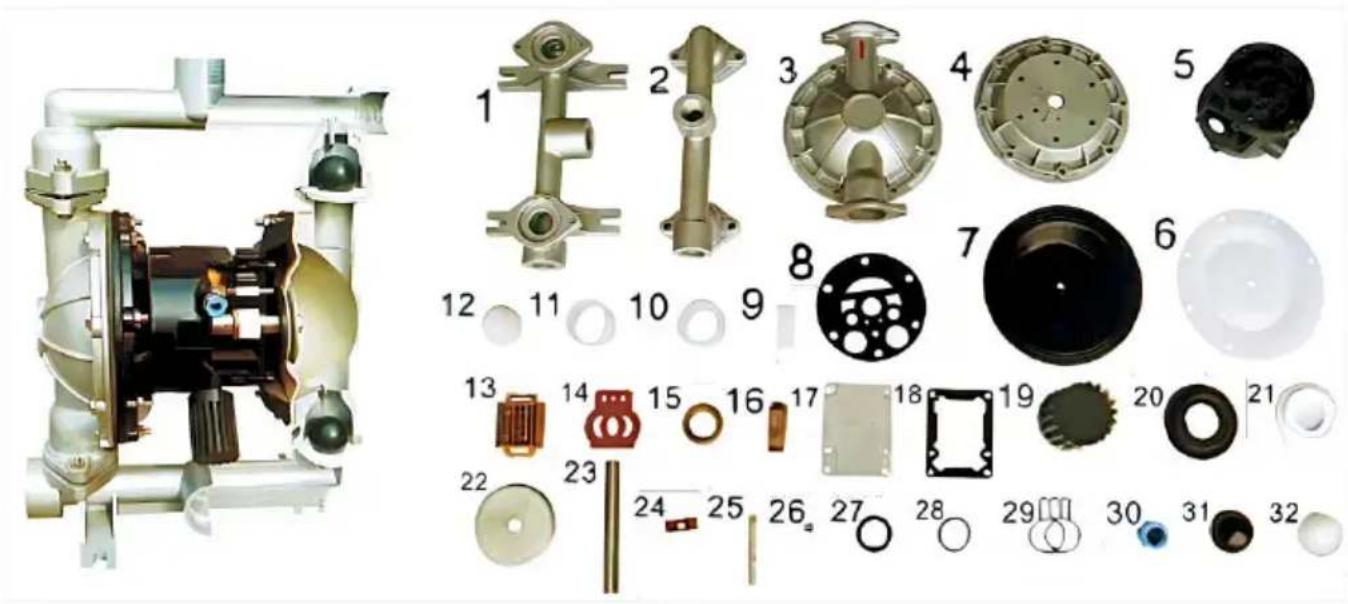
| No. | Name | Qty | Material |
| 1 | Inlet pipe | 1 | Stainless steel, cast iron, aluminium alloy, plastic, inner lining FEP |
| 2 | Outlet pipe | 1 | Stainless steel, cast iron, aluminium alloy, plastic, inner lining FEP |
| 3 | Pump body | 2 | Stainless steel, cast iron, aluminium alloy, plastic, inner lining FEP |
| 4 | Pump chamber | 2 | Aluminium alloy, cast iron |
| 5 | Intermediate | 1 | Aluminium alloy |
| 6 | Diaphragm vane | 2 | PTFE |
| 7 | Diaphragm vane | 2 | Acrylonitrile butadiene rubber, polychloroprene |
| 8 | ntermediate sealgasket | 2 | Acrylonitrile butadiene rubber |
| 9 | Driving shaft housing | 2 | Plastic |
| 10 | Connecting rod shaft housing | 2 | Plastic |
| 11 | Piston bush | 2 | Plastic |
| 12 | Piston | 2 | Plastic |
| 13 | Slipper block | 1 | Aluminium alloy |
| 14 | Slipper block | 1 | Chromium-plated steel |
| 15 | Sealing slip ring | 1 | Plastic |
| 16 | Driving slipper block | 1 | Plastic |
| 17 | Cover plate | 1 | Aluminium alloy |
| 18 | Cover plate gasket | 1 | Rubber |
| 19 | Muffler | 1 | Plastic |
| 20 | Seal seat | 4 | Rubber |
| 21 | Seal seat | 4 | PTFE |
| 22 | Clamping bar | 4 | Stainless steel, carbon steel |
| 23 | Connecting rod | 1 | Stainless steel |
| 24 | Compression spring | 1 | Copper |
| 25 | Driving shaft | 1 | Stainless steel |
| 26 | Seal ring of driving shaft | 2 | Rubber |
| 27 | Y-type O-ring | 4 | Rubber |
| 28 | O-ring | 1 | Rubber |
| 29 | Butterfly-type O-ring | 1 | Rubber |
| 30 | Inlet nozzle | 1 | Copper |
| 31 | Ball sealer | 4 | Rubber |
| 32 | Ball sealer | 4 | Stainless steel, ceramic, PTFE |
MATTERS NEED ATTENTION
| Malfunction forms | Causes | Troubleshooting |
| No water comes out from the pump or the flow is insufficient. | 1、The air pressure is insufficient.2、The flow channel of the pump cavity is blocked3、The valve is not opened | 1、Add the air pressure 2、Open the pump cavity for cleaning 3、Open the valve |
| The pump stops its operation | 1、The air distribution valve is damaged2、The diaphragm is damaged3、The muffler is blocked4、Air leakage occurs in the conn-eciting rod seal | 1、Repair or replace the air distribution valve2、Replace the diaphragm3、Clean the muffler.4、Replace the connecting rod seal |
| The lift is too low | 1、The suction valve is damaged2、The flow is too high3、The air pressure is too low | 1、Shotten the pipe and reduce elbows2、Turn down the drain valve.3、Add the air pressure |
| The noise is too low | 1、The muffler is broken | 1、Add the air pressure. |
Made in China
VEVOR®
TOUGH TOOLS, HALF PRICE
www.vevor.com/support
VEVOR®
TOUGH TOOLS, HALF PRICE
We continue to be committed to providing you with tools at competitive prices. "Save Half", "Half Price", or any other similar expressions used by us only represent an estimate of savings you might benefit from buying certain tools with us compared to top brands, and does not necessarily mean to cover all categories of tools offered. We kindly remind you to verify carefully when placing an order with us whether you are actually saving half in comparison with the top major brands.
VEVOR®
TOUGH TOOLS, HALF PRICE
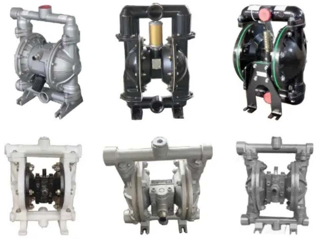
Air Operated Double
Diaphragm Pump
MODEL: QBK-40L/QBY4-50L/QBY4-25L/QBY4-25LF46 /
QBY-15PP/QBK-15P/QBK-15
NEED HELP? CONTACT US!
Have product questions? Need technical support? Please feel free to contact us:
Technical Support and E-Warranty Certificate
www.vevor.com/support
This is the original instruction. Please read all manual instructions carefully before operating. VEVOR reserves the right to interpret the user manual. The appearance of the product shall be subject to the product you received. Please forgive us that we won't inform you of any technology or software updates on our product.

PRODUCT PRESENTATION
PERFORMANCE CHARACTERISTICS
Note: Affected by the stability of gas supply and the environment, the parameters may have certain fluctuations or errors, which is a normal phenomenon.
| Model | Cmax(GPM) | Hmax(m) | pressuse(kgf/cm2) | suckedlift(m) | MaxgainDia(kgf/cm2) | Max pressure(pSI) | MWP | Pump |
| (6PM) | (perssuse(m) | (kgf/cm2) | (Dia(mm)) | (kgf/cm2) | ||||
| OBR-40L | 44 | 69 | 6.9 | 5 | 4.5 | 7 | 115 | 1.5" |
| OBR4-50L | 75 | 75 | 8.0 | 7 | 8.0 | 8 | 113 | 2.0" |
| OBR4-25L | 22 | 73 | 8.0 | 7 | 4.0 | 8 | 100 | 1.0" |
| OBRY4-25LF46 | 24 | 70 | 8.0 | 7 | 4.0 | 8 | 100 | 1.0" |
| OBRY-15PP | 2.5 | 50 | 6.0 | 5 | 1.0 | 7 | 80 | 1/2" |
| OBR-15P | 3 | 60 | 6.9 | 5 | 1.0 | 7 | 90 | 1/2" |
| OBR-15 | 3 | 60 | 6.9 | 5 | 1.0 | 7 | 90 | 1/2" |
QBK INSTALLATION SIZE CHART
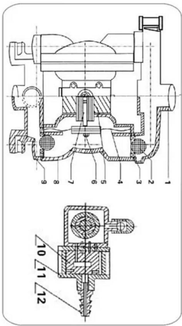
| QBY-10Structural drawing | |
| 01. Outlet pipe | 02. Ball sealer |
| 03. Seal seat | 04. Diaphragm vane |
| 05. Intermediate | 06. Connecting components |
| 07. Copperroads | 08. Pump body |
| 09. Inlet pipe | 10. Valve play |
| 12. Admi Ion piece | 13. Air distribution valve |
FLANGE CONNECTION TYPE
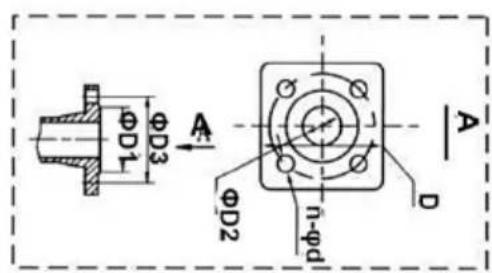
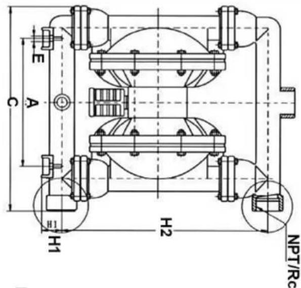
| GBY-50~100 Structural drawing | |
| 01. Admi Ion piece | 02. Air distribution valve |
| 03. Air distribution valve | 04.Bail sealar |
| 05. Seal seal | 06. Diaphragm vane |
| 07. Connecting components | 08. Copper roads |
| 09. Intermediate | 10. Inft pipe |
| 11. Air outlet | 12. Outlet pipe |
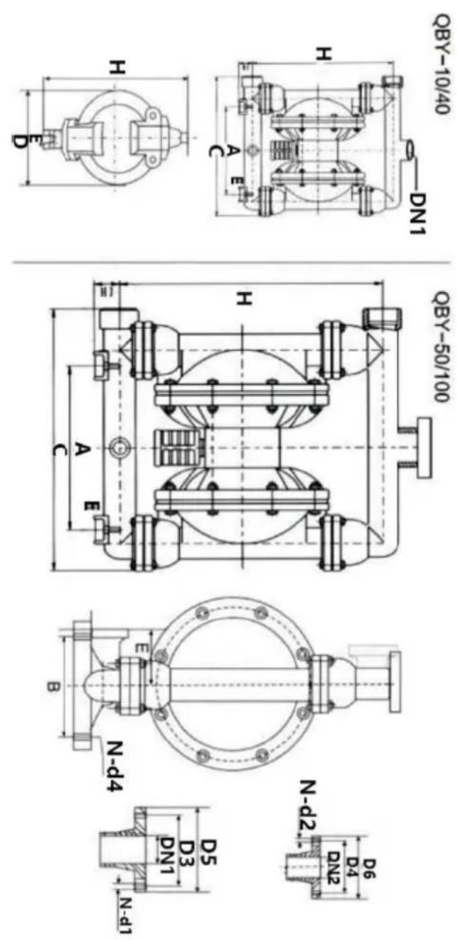
| Model | A | B | D5 | D6 | C | H | H1 | H2 | DHI | DN2 | N-D1 | N-D2 | D3 | D4 | E | N-d4 | Outside diameter or ink | Materials |
| OBY-10 (ZL104) (ICR18N9TI) (pp) | 53 | / | 190 | 235 | 35 | 220 | 3/8"Threaded | / | / | / | / | / | 12 | / | 8 | (HT200) | ||
| OBY-15 | 135 | 53 | / | 190 | 235 | 35 | 220 | 1/2"Threaded | / | / | / | / | / | 12 | / | 8 | ||
| OBY-25 | 255 | 150 | 100 | 380 | 530 | 70 | 1"Threaded | 4-Φ11 | 4-Φ11 | 75 | 75 | 55 | 4-Φ10 | 10 | 10 | |||
| OBY-40 | 255 | 150 | 130 | 120 | 380 | 530 | 70 | 11/2"Threaded | 4-Φ13.5 | 4-Φ13.5 | 100 | 90 | 55 | 4-Φ10 | 10 | |||
| OBY-25 | 220 | 160 | 100 | 370 | 460 | 50 | 410 | 1"Threaded | 4-Φ11 | 4-Φ11 | 75 | 75 | 80 | 4-Φ12 | 10 | |||
| OBY-40 | 220 | 160 | 130 | 120 | 370 | 460 | 410 | 11/2"Threaded | 11/4"Threaded | 4-Φ13.5 | 100 | 90 | 4-Φ12 | 10 | ||||
| OBY-50 | 340 | 215 | 140 | 140 | 550 | 715 | 95 | 2"Range | 4-Φ13.5 | 4-Φ13.5 | 110 | 110 | 145 | 4-Φ17.5 | 12 | |||
| OBY-65 | 340 | 215 | 160 | 140 | 550 | 715 | 95 | 21⁄2"Range | 4-Φ13.5 | 4-Φ13.5 | 130 | 130 | 145 | 4-Φ17.5 | 12 | |||
| OBY-80 | 360 | 260 | 190 | 190 | 580 | 950 | 100 | 3"Range | 4-Φ17.5 | 4-Φ17.5 | 150 | 150 | 130 | 4-Φ17.5 | 12 | |||
| OBY-100 | 360 | 260 | 210 | 190 | 580 | 950 | 100 | 4"Range | 3"Range | 4-Φ17.5 | 4-Φ17.5 | 170 | 170 | 130 | 4-Φ17.5 | 12 |
STRUCTURE DRAWING AND PARTS LIST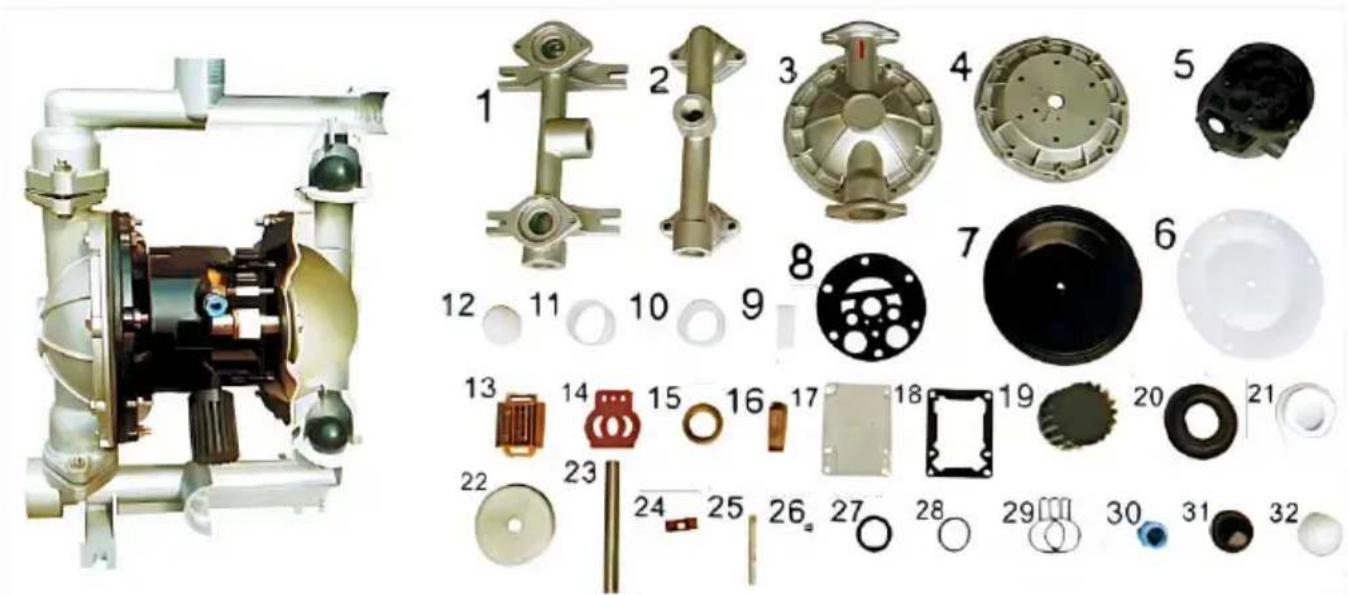
| No. | Name | Qty | Material |
| 1 | Inlet pipe | 1 | Stainless steel, cast iron, aluminium alloy, plastic, inner lining FEP |
| 2 | Outlet pipe | 1 | Stainless steel, cast iron, aluminium alloy, plastic, inner lining FEP |
| 3 | Pump body | 2 | Stainless steel, cast iron, aluminium alloy, plastic, inner lining FEP |
| 4 | Pump chamber | 2 | Aluminium alloy, cast iron |
| 5 | Intermediate | 1 | Aluminium alloy |
| 6 | Diaphragm vane | 2 | PTFE |
| 7 | Diaphragm vane | 2 | Acrylonitrile butadiene rubber, polychloroprene |
| 8 | ntermediate sealgasket | 2 | Acrylonitrile butadiene rubber |
| 9 | Driving shaft housing | 2 | Plastic |
| 10 | Connecting rod shaft housing | 2 | Plastic |
| 11 | Piston bush | 2 | Plastic |
| 12 | Piston | 2 | Plastic |
| 13 | Slipper block | 1 | Aluminium alloy |
| 14 | Slipper block | 1 | Chromium-plated steel |
| 15 | Sealing slip ring | 1 | Plastic |
| 16 | Driving slipper block | 1 | Plastic |
| 17 | Cover plate | 1 | Aluminium alloy |
| 18 | Cover plate gasket | 1 | Rubber |
| 19 | Muffler | 1 | Plastic |
| 20 | Seal seat | 4 | Rubber |
| 21 | Seal seat | 4 | PTFE |
| 22 | Clamping bar | 4 | Stainless steel, carbon steel |
| 23 | Connecting rod | 1 | Stainless steel |
| 24 | Compression spring | 1 | Copper |
| 25 | Driving shaft | 1 | Stainless steel |
| 26 | Seal ring of driving shaft | 2 | Rubber |
| 27 | Y-type O-ring | 4 | Rubber |
| 28 | O-ring | 1 | Rubber |
| 29 | Butterfly-type O-ring | 1 | Rubber |
| 30 | Inlet nozzle | 1 | Copper |
| 31 | Ball sealer | 4 | Rubber |
| 32 | Ball sealer | 4 | Stainless steel, ceramic, PTFE |
MATTERS NEED ATTENTION
| Malfunction forms | Causes | Troubleshooting |
| No water comes out from the pump or the flow is insufficient. | 1、The air pressure is insufficient.2、The flow channel of the pump cavity is blocked3、The valve is not opened | 1、Add the air pressure 2、Open the pump cavity for cleaning 3、Open the valve |
| The pump stops its operation | 1、The air distribution valve is damaged2、The diaphragm is damaged3、The muffler is blocked4、Air leakage occurs in the conn-eciting rod seal | 1、Repair or replace the air distribution valve2、Replace the diaphragm3、Clean the muffler.4、Replace the connecting rod seal |
| The lift is too low | 1、The suction valve is damaged2、The flow is too high3、The air pressure is too low | 1、Shotten the pipe and reduce elbows2、Turn down the drain valve.3、Add the air pressure |
| The noise is too low | 1、The muffler is broken | 1、Add the air pressure. |
Made in China
VEVOR®
TOUGH TOOLS, HALF PRICE
www.vevor.com/support
VEVOR®
TOUGH TOOLS, HALF PRICE
We continue to be committed to providing you with tools at competitive prices. "Save Half", "Half Price", or any other similar expressions used by us only represent an estimate of savings you might benefit from buying certain tools with us compared to top brands, and does not necessarily mean that all categories of tools offered will actually save you half compared to the top major brands. Please verify carefully when placing an order with us.
VEVOR®
TOUGH TOOLS, HALF PRICE
Air Operated Double Diaphragm Pump
MODEL: QBK-40L/QBY4-50L/QBY4-25L/QBY4-25LF46 / QBY-15PP/QBK-15P/QBK-15
NEED HELP? CONTACT US!
Have product questions? Need technical support? Please feel free to contact us:
Technical Support and E-Warranty Certificate www.vevor.com/support
This is the original instruction. Please read all manual instructions carefully before operating. VEVOR reserves the right to interpret the user manual. The appearance of the product shall be subject to the product you received. Please forgive us that we won't inform you of any technology or software updates on our product.

PRODUCT PRESENTATION
PERFORMANCE CHARACTERISTICS
Note: Affected by the stability of gas supply and the environment, the parameters may have certain fluctuations or errors, which is a normal phenomenon.
| Model | Cmax(GPM) | Hmax(m) | pressuse(kgf/cm2) | suckedlift(m) | MaxgainDia(kgf/cm2) | Max pressure(pSI) | MWP | Pump |
| (6PM) | (perssuse(m) | (kgf/cm2) | (Dia(mm)) | (kgf/cm2) | ||||
| OBR-40L | 44 | 69 | 6.9 | 5 | 4.5 | 7 | 115 | 1.5" |
| OBR4-50L | 75 | 75 | 8.0 | 7 | 8.0 | 8 | 113 | 2.0" |
| OBR4-25L | 22 | 73 | 8.0 | 7 | 4.0 | 8 | 100 | 1.0" |
| OBRY4-25LF46 | 24 | 70 | 8.0 | 7 | 4.0 | 8 | 100 | 1.0" |
| OBRY-15PP | 2.5 | 50 | 6.0 | 5 | 1.0 | 7 | 80 | 1/2" |
| OBR-15P | 3 | 60 | 6.9 | 5 | 1.0 | 7 | 90 | 1/2" |
| OBR-15 | 3 | 60 | 6.9 | 5 | 1.0 | 7 | 90 | 1/2" |
QBK INSTALLATION SIZE CHART
| QBY-10Structural drawing | |
| 01. Outlet pipe | 02. Ball sealer |
| 03. Seal seat | 04. Diaphragm vane |
| 05. Intermediate | 06. Connecting components |
| 07. Copperroads | 08. Pump body |
| 09. Inlet pipe | 10. Valve play |
| 12. Admi Ion piece | 13. Air distribution valve |
FLANGE CONNECTION TYPE
| GBY-50~100 Structural drawing | |
| 01. Admi Ion piece | 02. Air distribution valve |
| 03. Air distribution valve | 04.Bail sealar |
| 05. Seal seal | 06. Diaphragm vane |
| 07. Connecting components | 08. Copper roads |
| 09. Intermediate | 10. Inft pipe |
| 11. Air outlet | 12. Outlet pipe |
| Model | A | B | D5 | D6 | C | H | H1 | H2 | DHI | DN2 | N-D1 | N-D2 | D3 | D4 | E | N-d4 | Outside diameter or ink | Materials |
| OBY-10 (ZL104) (ICR18N9TI) (pp) | 53 | / | 190 | 235 | 35 | 220 | 3/8"Threaded | / | / | / | / | / | 12 | / | 8 | (HT200) | ||
| OBY-15 | 135 | 53 | / | 190 | 235 | 35 | 220 | 1/2"Threaded | / | / | / | / | / | 12 | / | 8 | ||
| OBY-25 | 255 | 150 | 100 | 380 | 530 | 70 | 1"Threaded | 4-Φ11 | 4-Φ11 | 75 | 75 | 55 | 4-Φ10 | 10 | 10 | |||
| OBY-40 | 255 | 150 | 130 | 120 | 380 | 530 | 70 | 11/2"Threaded | 4-Φ13.5 | 4-Φ13.5 | 100 | 90 | 55 | 4-Φ10 | 10 | |||
| OBY-25 | 220 | 160 | 100 | 370 | 460 | 50 | 410 | 1"Threaded | 4-Φ11 | 4-Φ11 | 75 | 75 | 80 | 4-Φ12 | 10 | |||
| OBY-40 | 220 | 160 | 130 | 120 | 370 | 460 | 410 | 11/2"Threaded | 11/4"Threaded | 4-Φ13.5 | 100 | 90 | 4-Φ12 | 10 | ||||
| OBY-50 | 340 | 215 | 140 | 140 | 550 | 715 | 95 | 2"Range | 4-Φ13.5 | 4-Φ13.5 | 110 | 110 | 145 | 4-Φ17.5 | 12 | |||
| OBY-65 | 340 | 215 | 160 | 140 | 550 | 715 | 95 | 21⁄2"Range | 4-Φ13.5 | 4-Φ13.5 | 130 | 130 | 145 | 4-Φ17.5 | 12 | |||
| OBY-80 | 360 | 260 | 190 | 190 | 580 | 950 | 100 | 3"Range | 4-Φ17.5 | 4-Φ17.5 | 150 | 150 | 130 | 4-Φ17.5 | 12 | |||
| OBY-100 | 360 | 260 | 210 | 190 | 580 | 950 | 100 | 4"Range | 3"Range | 4-Φ17.5 | 4-Φ17.5 | 170 | 170 | 130 | 4-Φ17.5 | 12 |
STRUCTURE DRAWING AND PARTS LIST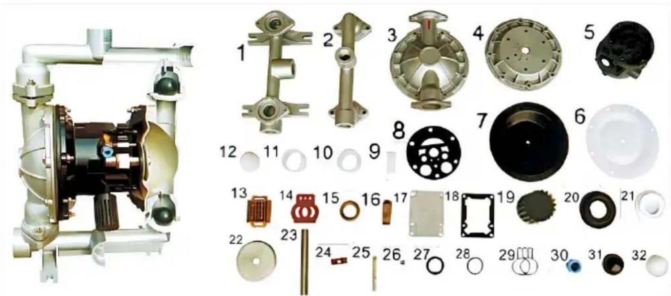
| No. | Name | Qty | Material |
| 1 | Inlet pipe | 1 | Stainless steel, cast iron, aluminium alloy, plastic, inner lining FEP |
| 2 | Outlet pipe | 1 | Stainless steel, cast iron, aluminium alloy, plastic, inner lining FEP |
| 3 | Pump body | 2 | Stainless steel, cast iron, aluminium alloy, plastic, inner lining FEP |
| 4 | Pump chamber | 2 | Aluminium alloy, cast iron |
| 5 | Intermediate | 1 | Aluminium alloy |
| 6 | Diaphragm vane | 2 | PTFE |
| 7 | Diaphragm vane | 2 | Acrylonitrile butadiene rubber, polychloroprene |
| 8 | ntermediate sealgasket | 2 | Acrylonitrile butadiene rubber |
| 9 | Driving shaft housing | 2 | Plastic |
| 10 | Connecting rod shaft housing | 2 | Plastic |
| 11 | Piston bush | 2 | Plastic |
| 12 | Piston | 2 | Plastic |
| 13 | Slipper block | 1 | Aluminium alloy |
| 14 | Slipper block | 1 | Chromium-plated steel |
| 15 | Sealing slip ring | 1 | Plastic |
| 16 | Driving slipper block | 1 | Plastic |
| 17 | Cover plate | 1 | Aluminium alloy |
| 18 | Cover plate gasket | 1 | Rubber |
| 19 | Muffler | 1 | Plastic |
| 20 | Seal seat | 4 | Rubber |
| 21 | Seal seat | 4 | PTFE |
| 22 | Clamping bar | 4 | Stainless steel, carbon steel |
| 23 | Connecting rod | 1 | Stainless steel |
| 24 | Compression spring | 1 | Copper |
| 25 | Driving shaft | 1 | Stainless steel |
| 26 | Seal ring of driving shaft | 2 | Rubber |
| 27 | Y-type O-ring | 4 | Rubber |
| 28 | O-ring | 1 | Rubber |
| 29 | Butterfly-type O-ring | 1 | Rubber |
| 30 | Inlet nozzle | 1 | Copper |
| 31 | Ball sealer | 4 | Rubber |
| 32 | Ball sealer | 4 | Stainless steel, ceramic, PTFE |
MATTERS NEED ATTENTION
| Malfunction forms | Causes | Troubleshooting |
| No water comes out from the pump or the flow is insufficient. | 1、The air pressure is insufficient.2、The flow channel of the pump cavity is blocked3、The valve is not opened | 1、Add the air pressure 2、Open the pump cavity for cleaning 3、Open the valve |
| The pump stops its operation | 1、The air distribution valve is damaged2、The diaphragm is damaged3、The muffler is blocked4、Air leakage occurs in the conn-eciting rod seal | 1、Repair or replace the air distribution valve2、Replace the diaphragm3、Clean the muffler.4、Replace the connecting rod seal |
| The lift is too low | 1、The suction valve is damaged2、The flow is too high3、The air pressure is too low | 1、Shotten the pipe and reduce elbows2、Turn down the drain valve.3、Add the air pressure |
| The noise is too low | 1、The muffler is broken | 1、Add the air pressure. |
www.vevor.com/support
VEVOR®
TOUGH TOOLS, HALF PRICE
Technical Support and e-warranty certificate www.vevor.com/support
We continue to be committed to provide you tools with competitive price. "Save Half", "Half Price" or any other similar expressions used by us only represent estimate of savings you might benefit from buying certain tools with us compared to top brands and does not necessarily mean to cover all categories of tools offered are kindly reminded to verify carefully when you are placing an order with us actually saving half in comparison with the top major brands.
VEVOR®
TOUGH TOOLS, HALF PRICE
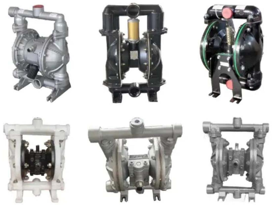
Air Operated Double Diaphragm Pump
MODEL: QBK-40L/QBY4-50L/QBY4-25L/QBY4-25LF46 / QBY-15PP/QBK-15P/QBK-15
NEED HELP? CONTACT US!
Have product questions? Need technical support? Please feel free to contact us:
Technical Support and E-Warranty Certificate www.vevor.com/support
This is the original instruction. Please read all manual instructions carefully before operating. VEVOR reserves a clear interpretation of the user manual. The appearance of the product shall be subject to the product you received. Please forgive us that we won't inform you if there are any technology or software updates on our product.

PRODUCT PRESENTATION
PERFORMANCE CHARACTERISTICS
Note: Affected by the stability of gas supply and the environment, the parameters may have certain fluctuations or errors, which is a normal phenomenon.
| Model | Cmax(GPM) | Hmax(m) | pressuse(kgf/cm2) | suckedlift(m) | MaxgainDia(pms)(kgf/cm2) | MWP(pSI) | Air InletSIZE |
| OBR-40L | 44 | 69 | 6.9 | 5 | 4.5 | 115 | |
| OBRY4-50L | 75 | 75 | 8.0 | 7 | 8.0 | 8 | 113 |
| OBRY4-25L | 22 | 73 | 8.0 | 7 | 4.0 | 8 | 100 |
| OBRY4-25LF46 | 24 | 70 | 8.0 | 7 | 4.0 | 8 | 100 |
| OBRY-15PP | 2.5 | 50 | 6.0 | 5 | 1.0 | 7 | 80 |
| OBRK-15P | 3 | 60 | 6.9 | 5 | 1.0 | 7 | 90 |
| OBRK-15 | 3 | 60 | 6.9 | 5 | 1.0 | 7 | 90 |
QBK INSTALLATION SIZE CHART
| QBY-10Structural drawing | |
| 01. Outlet pipe | 02. Ball sealer |
| 03. Seal seat | 04. Diaphragm vane |
| 05. Intermediate | 06. Connecting components |
| 07. Copperroads | 08. Pump body |
| 09. Inlet pipe | 10. Valve play |
| 12. Admi Ion piece | 13. Air distribution valve |
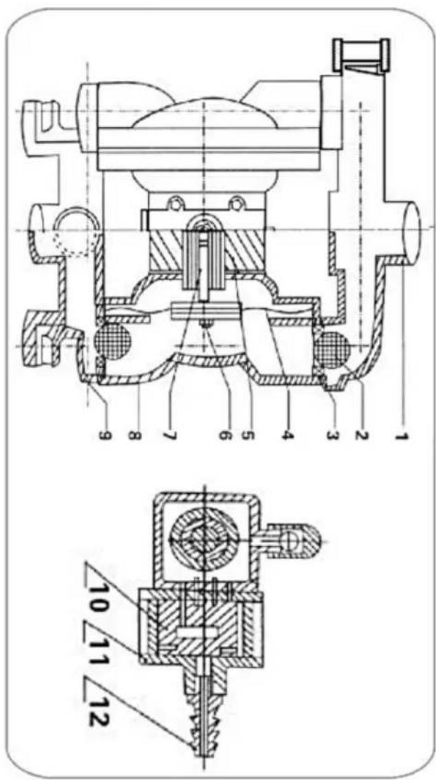
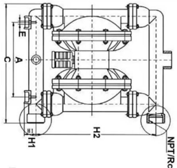
FLANGE CONNECTION TYPE
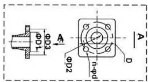
| GBY-50~100 Structural drawing | |
| 01. Admi Ion piece | 02. Air distribution valve |
| 03. Air distribution valve | 04.Bail sealar |
| 05. Seal seal | 06. Diaphragm vane |
| 07. Connecting components | 08. Copper roads |
| 09. Intermediate | 10. Inft pipe |
| 11. Air outlet | 12. Outlet pipe |
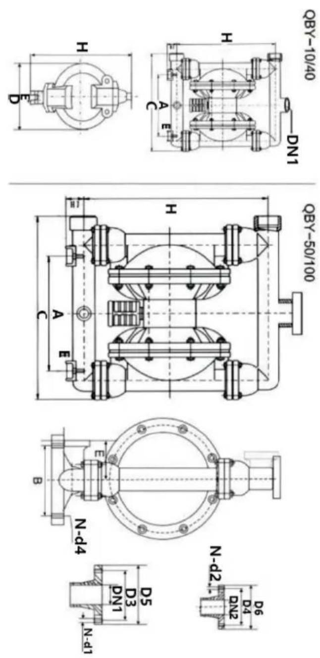
| Model | A | B | D5 | D6 | C | H | H1 | H2 | DHI | DN2 | N-D1 | N-D2 | D3 | D4 | E | N-d4 | Outside diameter or ink† | Materials |
| OBY-10 (ZL104) (ICR18N9TI) (pp) | 53 | / | 190 | 235 | 35 | 220 | 3/8"Threaded | / | / | / | / | / | 12 | / | 8 | (HT200) | ||
| OBY-15 | 135 | 53 | / | 190 | 235 | 35 | 220 | 1/2"Threaded | / | / | / | / | / | 12 | / | 8 | ||
| OBY-25 | 255 | 150 | 100 | 380 | 530 | 70 | 1"Threaded | 4-Φ11 | 4-Φ11 | 75 | 75 | 55 | 4-Φ10 | 10 | (PP) Impacts and exports are facing the edge | |||
| OBY-40 | 255 | 150 | 130 | 120 | 380 | 530 | 70 | 11/2"Threaded | 4-Φ13.5 | 4-Φ13.5 | 100 | 90 | 55 | 4-Φ10 | 10 | |||
| OBY-25 | 220 | 160 | 100 | 100 | 370 | 460 | 50 | 410 | 1"Threaded | 4-Φ11 | 4-Φ11 | 75 | 75 | 80 | 4-Φ12 | 10 | ||
| OBY-40 | 220 | 160 | 130 | 120 | 370 | 460 | 410 | 11/2"Threaded | 4-Φ13.5 | 4-Φ13.5 | 100 | 90 | 4-Φ12 | 10 | ||||
| OBY-50 | 340 | 215 | 140 | 140 | 550 | 715 | 95 | 2"Range | 4-Φ13.5 | 4-Φ13.5 | 110 | 110 | 145 | 4-Φ17.5 | 12 | |||
| OBY-65 | 340 | 215 | 160 | 140 | 550 | 715 | 95 | 21⁄2"Range | 4-Φ13.5 | 4-Φ13.5 | 130 | 130 | 145 | 4-Φ17.5 | 12 | |||
| OBY-80 | 360 | 260 | 190 | 190 | 580 | 950 | 100 | 3"Range | 4-Φ17.5 | 4-Φ17.5 | 150 | 150 | 130 | 4-Φ17.5 | 12 | |||
| OBY-100 | 360 | 260 | 210 | 190 | 580 | 950 | 100 | 4"Range | 3"Range | 4-Φ17.5 | 4-Φ17.5 | 170 | 170 | 130 | 4-Φ17.5 | 12 |
STRUCTURE DRAWING AND PARTS LIST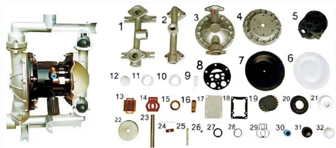
| No. | Name | Qty | Material |
| 1 | Inlet pipe | 1 | Stainless steel, cast iron, aluminium alloy, plastic, inner lining FEP |
| 2 | Outlet pipe | 1 | Stainless steel, cast iron, aluminium alloy, plastic, inner lining FEP |
| 3 | Pump body | 2 | Stainless steel, cast iron, aluminium alloy, plastic, inner lining FEP |
| 4 | Pump chamber | 2 | Aluminium alloy, cast iron |
| 5 | Intermediate | 1 | Aluminium alloy |
| 6 | Diaphragm vane | 2 | PTFE |
| 7 | Diaphragm vane | 2 | Acrylonitrile butadiene rubber, polychloroprene |
| 8 | ntermediate sealgasket | 2 | Acrylonitrile butadiene rubber |
| 9 | Driving shaft housing | 2 | Plastic |
| 10 | Connecting rod shaft housing | 2 | Plastic |
| 11 | Piston bush | 2 | Plastic |
| 12 | Piston | 2 | Plastic |
| 13 | Slipper block | 1 | Aluminium alloy |
| 14 | Slipper block | 1 | Chromium-plated steel |
| 15 | Sealing slip ring | 1 | Plastic |
| 16 | Driving slipper block | 1 | Plastic |
| 17 | Cover plate | 1 | Aluminium alloy |
| 18 | Cover plate gasket | 1 | Rubber |
| 19 | Muffler | 1 | Plastic |
| 20 | Seal seat | 4 | Rubber |
| 21 | Seal seat | 4 | PTFE |
| 22 | Clamping bar | 4 | Stainless steel, carbon steel |
| 23 | Connecting rod | 1 | Stainless steel |
| 24 | Compression spring | 1 | Copper |
| 25 | Driving shaft | 1 | Stainless steel |
| 26 | Seal ring of driving shaft | 2 | Rubber |
| 27 | Y-type O-ring | 4 | Rubber |
| 28 | O-ring | 1 | Rubber |
| 29 | Butterfly-type O-ring | 1 | Rubber |
| 30 | Inlet nozzle | 1 | Copper |
| 31 | Ball sealer | 4 | Rubber |
| 32 | Ball sealer | 4 | Stainless steel, ceramic, PTFE |
MATTERS NEED ATTENTION
| Malfunction forms | Causes | Troubleshooting |
| No water comes out from the pump or the flow is insufficient. | 1、The air pressure is insufficient.2、The flow channel of the pump cavity is blocked3、The valve is not opened | 1、Add the air pressure 2、Open the pump cavity for cleaning 3、Open the valve |
| The pump stops its operation | 1、The air distribution valve is damaged2、The diaphragm is damaged3、The muffler is blocked4、Air leakage occurs in the conn-eciting rod seal | 1、Repair or replace the air distribution valve2、Replace the diaphragm3、Clean the muffler.4、Replace the connecting rod seal |
| The lift is too low | 1、The suction valve is damaged2、The flow is too high3、The air pressure is too low | 1、Shotten the pipe and reduce elbows2、Turn down the drain valve.3、Add the air pressure |
| The noise is too low | 1、The muffler is broken | 1、Add the air pressure. |
Made in China
VEVOR®
TOUGH TOOLS, HALF PRICE
www.vevor.com/support
VEVOR®
TOUGH TOOLS, HALF PRICE
We continue to be committed to providing you tools with competitive prices. "Save Half", "Half Price" or any other similar expressions used by us only represent an estimate of savings you might benefit from buying certain tools with us compared to top brands, and does not necessarily mean to cover all categories of tools offered. We kindly remind you to verify carefully when placing an order with us to ensure you are actually saving half in comparison with the top major brands.
VEVOR®
TOUGH TOOLS, HALF PRICE
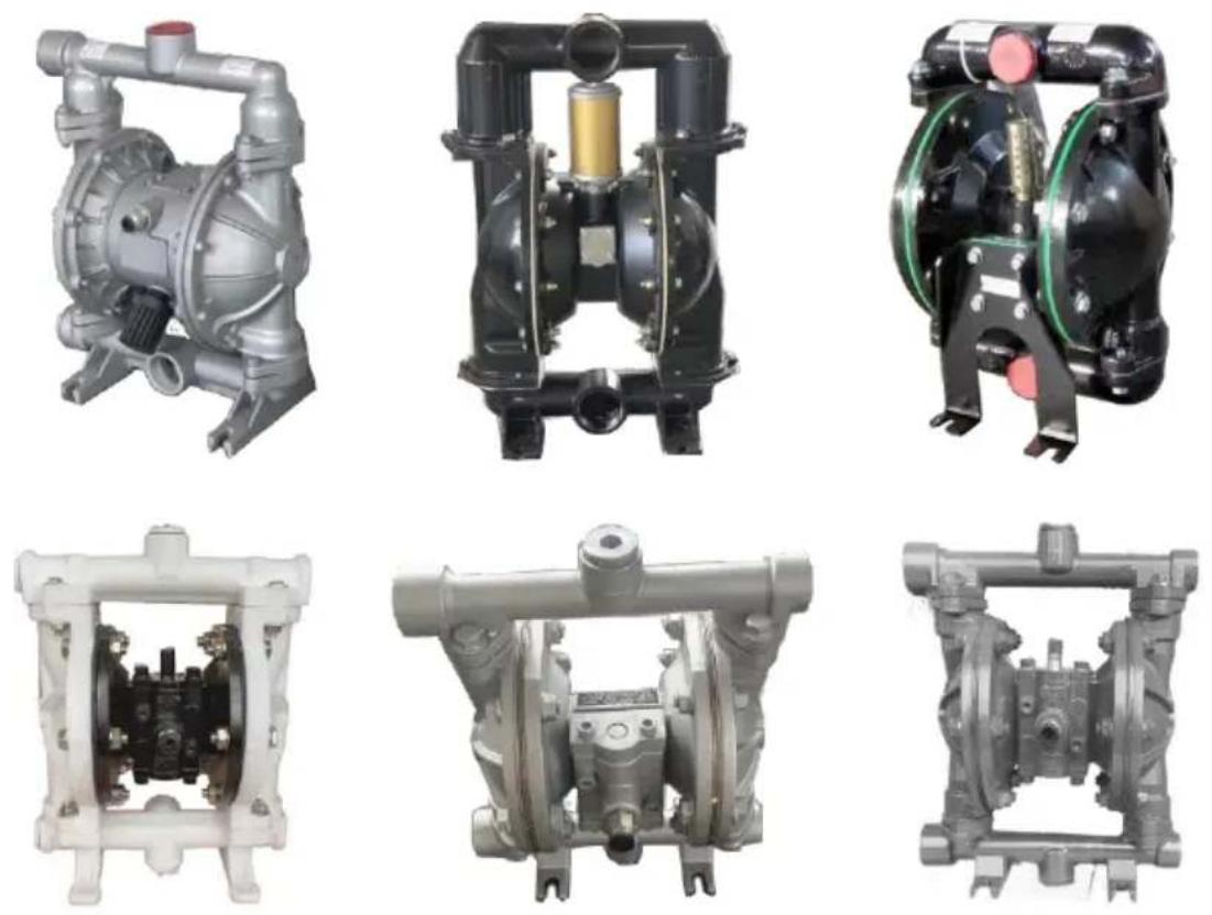
Air Operated Double Diaphragm Pump
MODEL: QBK-40L/QBY4-50L/QBY4-25L/QBY4-25LF46 / QBY-15PP/QBK-15P/QBK-15
NEED HELP? CONTACT US!
Have product questions? Need technical support? Please feel free to contact us:
Technical Support and E-Warranty Certificate www.vevor.com/support
This is the original instruction. Please read all manual instructions carefully before operating. VEVOR reserves a clear interpretation of the user manual. The appearance of the product shall be subject to the product you received. Please forgive us that we won't inform you of any technology or software updates on our product.

PRODUCT PRESENTATION
PERFORMANCE CHARACTERISTICS
Note: Affected by the stability of gas supply and the environment, the parameters may have certain fluctuations or errors, which is a normal phenomenon.
| Model | Cmax(GPM) | Hmax(m) | pressuse(kgf/cm2) | suckedlift(m) | MaxgainDia(pms)(kgf/cm2) | MWP(pSI) | Air InletSIZE |
| OBR-40L | 44 | 69 | 6.9 | 5 | 4.5 | 115 | |
| OBRY4-50L | 75 | 75 | 8.0 | 7 | 8.0 | 8 | 113 |
| OBRY4-25L | 22 | 73 | 8.0 | 7 | 4.0 | 8 | 100 |
| OBRY4-25LF46 | 24 | 70 | 8.0 | 7 | 4.0 | 8 | 100 |
| OBRY-15PP | 2.5 | 50 | 6.0 | 5 | 1.0 | 7 | 80 |
| OBRK-15P | 3 | 60 | 6.9 | 5 | 1.0 | 7 | 90 |
| OBRK-15 | 3 | 60 | 6.9 | 5 | 1.0 | 7 | 90 |
QBK INSTALLATION SIZE CHART
| QBY-10Structural drawing | |
| 01. Outlet pipe | 02. Ball sealer |
| 03. Seal seat | 04. Diaphragm vane |
| 05. Intermediate | 06. Connecting components |
| 07. Copperroads | 08. Pump body |
| 09. Inlet pipe | 10. Valve play |
| 12. Admi Ion piece | 13. Air distribution valve |
FLANGE CONNECTION TYPE
| GBY-50~100 Structural drawing | |
| 01. Admi Ion piece | 02. Air distribution valve |
| 03. Air distribution valve | 04.Bail sealar |
| 05. Seal seal | 06. Diaphragm vane |
| 07. Connecting components | 08. Copper roads |
| 09. Intermediate | 10. Inft pipe |
| 11. Air outlet | 12. Outlet pipe |
| Model | A | B | D5 | D6 | C | H | H1 | H2 | DHI | DN2 | N-D1 | N-D2 | D3 | D4 | E | N-d4 | Outside diameter or ink† | Materials |
| OBY-10 (ZL104) (ICR18N9TI) (pp) | 53 | / | 190 | 235 | 35 | 220 | 3/8"Threaded | / | / | / | / | / | 12 | / | 8 | (HT200) | ||
| OBY-15 | 135 | 53 | / | 190 | 235 | 35 | 220 | 1/2"Threaded | / | / | / | / | / | 12 | / | 8 | ||
| OBY-25 | 255 | 150 | 100 | 380 | 530 | 70 | 1"Threaded | 4-Φ11 | 4-Φ11 | 75 | 75 | 55 | 4-Φ10 | 10 | (PP) Impacts and exports are facing the edge | |||
| OBY-40 | 255 | 150 | 130 | 120 | 380 | 530 | 70 | 11/2"Threaded | 4-Φ13.5 | 4-Φ13.5 | 100 | 90 | 55 | 4-Φ10 | 10 | |||
| OBY-25 | 220 | 160 | 100 | 100 | 370 | 460 | 50 | 410 | 1"Threaded | 4-Φ11 | 4-Φ11 | 75 | 75 | 80 | 4-Φ12 | 10 | ||
| OBY-40 | 220 | 160 | 130 | 120 | 370 | 460 | 410 | 11/2"Threaded | 4-Φ13.5 | 4-Φ13.5 | 100 | 90 | 4-Φ12 | 10 | ||||
| OBY-50 | 340 | 215 | 140 | 140 | 550 | 715 | 95 | 2"Range | 4-Φ13.5 | 4-Φ13.5 | 110 | 110 | 145 | 4-Φ17.5 | 12 | |||
| OBY-65 | 340 | 215 | 160 | 140 | 550 | 715 | 95 | 21⁄2"Range | 4-Φ13.5 | 4-Φ13.5 | 130 | 130 | 145 | 4-Φ17.5 | 12 | |||
| OBY-80 | 360 | 260 | 190 | 190 | 580 | 950 | 100 | 3"Range | 4-Φ17.5 | 4-Φ17.5 | 150 | 150 | 130 | 4-Φ17.5 | 12 | |||
| OBY-100 | 360 | 260 | 210 | 190 | 580 | 950 | 100 | 4"Range | 3"Range | 4-Φ17.5 | 4-Φ17.5 | 170 | 170 | 130 | 4-Φ17.5 | 12 |
STRUCTURE DRAWING AND PARTS LIST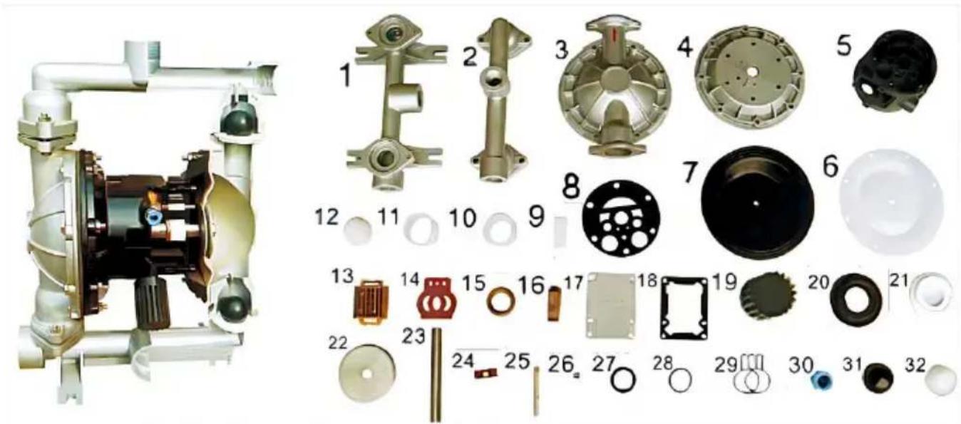
| No. | Name | Qty | Material |
| 1 | Inlet pipe | 1 | Stainless steel, cast iron, aluminium alloy, plastic, inner lining FEP |
| 2 | Outlet pipe | 1 | Stainless steel, cast iron, aluminium alloy, plastic, inner lining FEP |
| 3 | Pump body | 2 | Stainless steel, cast iron, aluminium alloy, plastic, inner lining FEP |
| 4 | Pump chamber | 2 | Aluminium alloy, cast iron |
| 5 | Intermediate | 1 | Aluminium alloy |
| 6 | Diaphragm vane | 2 | PTFE |
| 7 | Diaphragm vane | 2 | Acrylonitrile butadiene rubber, polychloroprene |
| 8 | ntermediate sealgasket | 2 | Acrylonitrile butadiene rubber |
| 9 | Driving shaft housing | 2 | Plastic |
| 10 | Connecting rod shaft housing | 2 | Plastic |
| 11 | Piston bush | 2 | Plastic |
| 12 | Piston | 2 | Plastic |
| 13 | Slipper block | 1 | Aluminium alloy |
| 14 | Slipper block | 1 | Chromium-plated steel |
| 15 | Sealing slip ring | 1 | Plastic |
| 16 | Driving slipper block | 1 | Plastic |
| 17 | Cover plate | 1 | Aluminium alloy |
| 18 | Cover plate gasket | 1 | Rubber |
| 19 | Muffler | 1 | Plastic |
| 20 | Seal seat | 4 | Rubber |
| 21 | Seal seat | 4 | PTFE |
| 22 | Clamping bar | 4 | Stainless steel, carbon steel |
| 23 | Connecting rod | 1 | Stainless steel |
| 24 | Compression spring | 1 | Copper |
| 25 | Driving shaft | 1 | Stainless steel |
| 26 | Seal ring of driving shaft | 2 | Rubber |
| 27 | Y-type O-ring | 4 | Rubber |
| 28 | O-ring | 1 | Rubber |
| 29 | Butterfly-type O-ring | 1 | Rubber |
| 30 | Inlet nozzle | 1 | Copper |
| 31 | Ball sealer | 4 | Rubber |
| 32 | Ball sealer | 4 | Stainless steel, ceramic, PTFE |
MATTERS NEED ATTENTION
| Malfunction forms | Causes | Troubleshooting |
| No water comes out from the pump or the flow is insufficient. | 1、The air pressure is insufficient.2、The flow channel of the pump cavity is blocked3、The valve is not opened | 1、Add the air pressure 2、Open the pump cavity for cleaning 3、Open the valve |
| The pump stops its operation | 1、The air distribution valve is damaged2、The diaphragm is damaged3、The muffler is blocked4、Air leakage occurs in the conn-eciting rod seal | 1、Repair or replace the air distribution valve2、Replace the diaphragm3、Clean the muffler.4、Replace the connecting rod seal |
| The lift is too low | 1、The suction valve is damaged2、The flow is too high3、The air pressure is too low | 1、Shotten the pipe and reduce elbows2、Turn down the drain valve.3、Add the air pressure |
| The noise is too low | 1、The muffler is broken | 1、Add the air pressure. |
Made in China
VEVOR®
TOUGH TOOLS, HALF PRICE
www.vevor.com/support
Brand : Vevor
Model : QBY4-50L
Category : Air pump