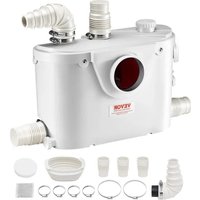
USER MANUAL FLO500-BE Vevor
Technical Support and E-Warranty Certificate www.vevor.com/support
MACERATOR PUMP
USER MANUAL
MODEL: FLO500-BE
We continue to be committed to providing you tools with competitive prices. "Save Half", "Half Price" or any other similar expressions used by us only represent an estimate of savings you might benefit from buying certain tools with us compared to the major top brands and do not necessarily mean to cover all categories of tools offered by us. You are kindly reminded to verify carefully when you are placing an order with us if you are actually saving half in comparison with the top major brands.
VEVOR®
TOUGH TOOLS, HALF PRICE
MACERATOR PUMP
MODEL: FLO500-BE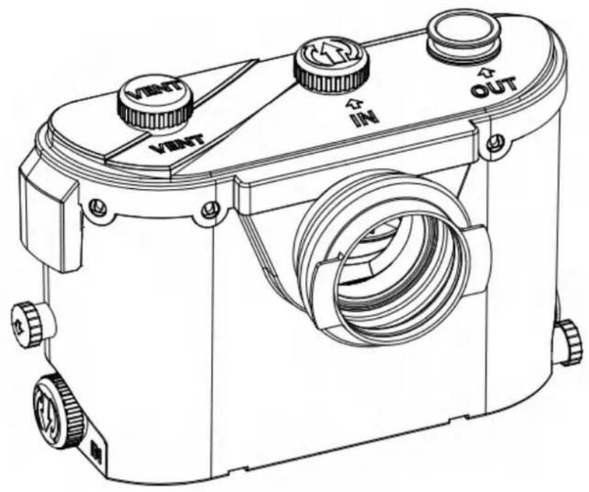
Have product questions? Need technical support? Please feel free to contact us:
Technical Support and E-Warranty Certificate
www.vevor.com/support
This is the original instruction. Please read all manual instructions carefully before operating. VEVOR reserves a clear interpretation of the user manual. The appearance of the product shall be subject to the product you received. Please forgive us that we won't inform you again if there are any technology or software updates on our product.
(1) F1500 water pump specially used indoors. This equipment is only suitable for wall-mounted toilets, that is, toilets with horizontal drain holes. We must follow the installation and maintenance instructions in this manual to make the water pump able to run normally. (2) If correctly installed and maintained according to the instructions in this user manual, it has strong functions, safe and reliable. The water pump will automatically start when the sewage reaches a certain water level. This equipment should avoid business or industrial use. (3) The normal application area of FIO500-BE refers to the treatment of human waste, toilet paper, and water.
FLO500-BE is only suitable for family use; it cannot handle hygiene covers, cotton plugs, sanitary towels, cotton bars, or other hygiene products, nor any hard objects.
FLO500-BE is specially designed to connect with:
· WC · Shower · Wash basin · Bidet · Kitchen · Urinal · Washing machine
1-2. FLO500-BE Specifications
| Model | Input | Max Power | Max Flow | Max Lift | Water Inlet | Water Outlet |
| FLO500-BE (US) | AC110-120V 60Hz | 0.7 HP | 29GPM | 26ft | WC+3 | 1 |
| FLO500-BE (EU) | AC220-240V 50Hz | 500 W | 110 LPM | 8m | WC+3 | 1 |
WARNING: Only installations conforming to the above specifications are acceptable.
- Installation (diagram)

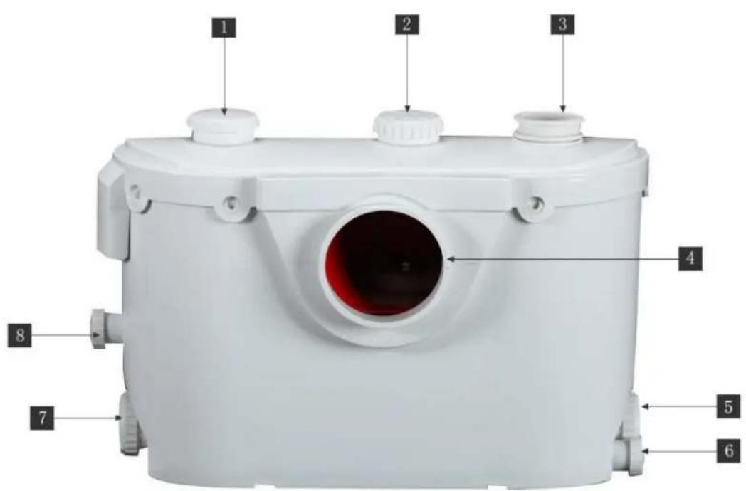
- Vent hole (carbon filter)
- Inlet sanitary fixture
- Outlet discharge pipe
- Inlet toilet
- Inlet sanitary fixture
6. Emergency outlet
- inlet sanitary fixture
8. Emergency outlet
3. Accessory List
A-B x1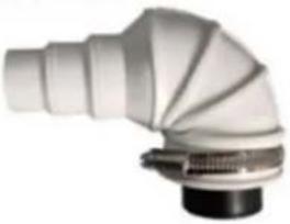 Elbow with Check Valve Elbow with Check Valve | C x3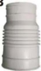 coupling hose coupling hose | D x1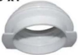 Rubber Ring Rubber Ring | E x6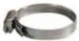 Clamp 32-50mm Clamp 32-50mm |
Fx1 Activated carbon Activated carbon | G x2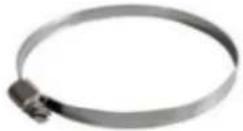 Clamp 90-110mmx1Clamp 100-120mmx1 Clamp 90-110mmx1Clamp 100-120mmx1 | H x2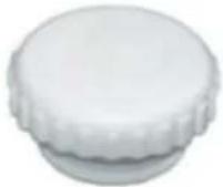 Blanking Plug Blanking Plug | J x1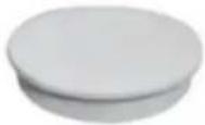 Lid Lid |
4. Connect water drainage pipeline
Install the rubber ring (D) which connects the toilet to the water pump unit, and use clamps (G) (90-110mm) to fix it.
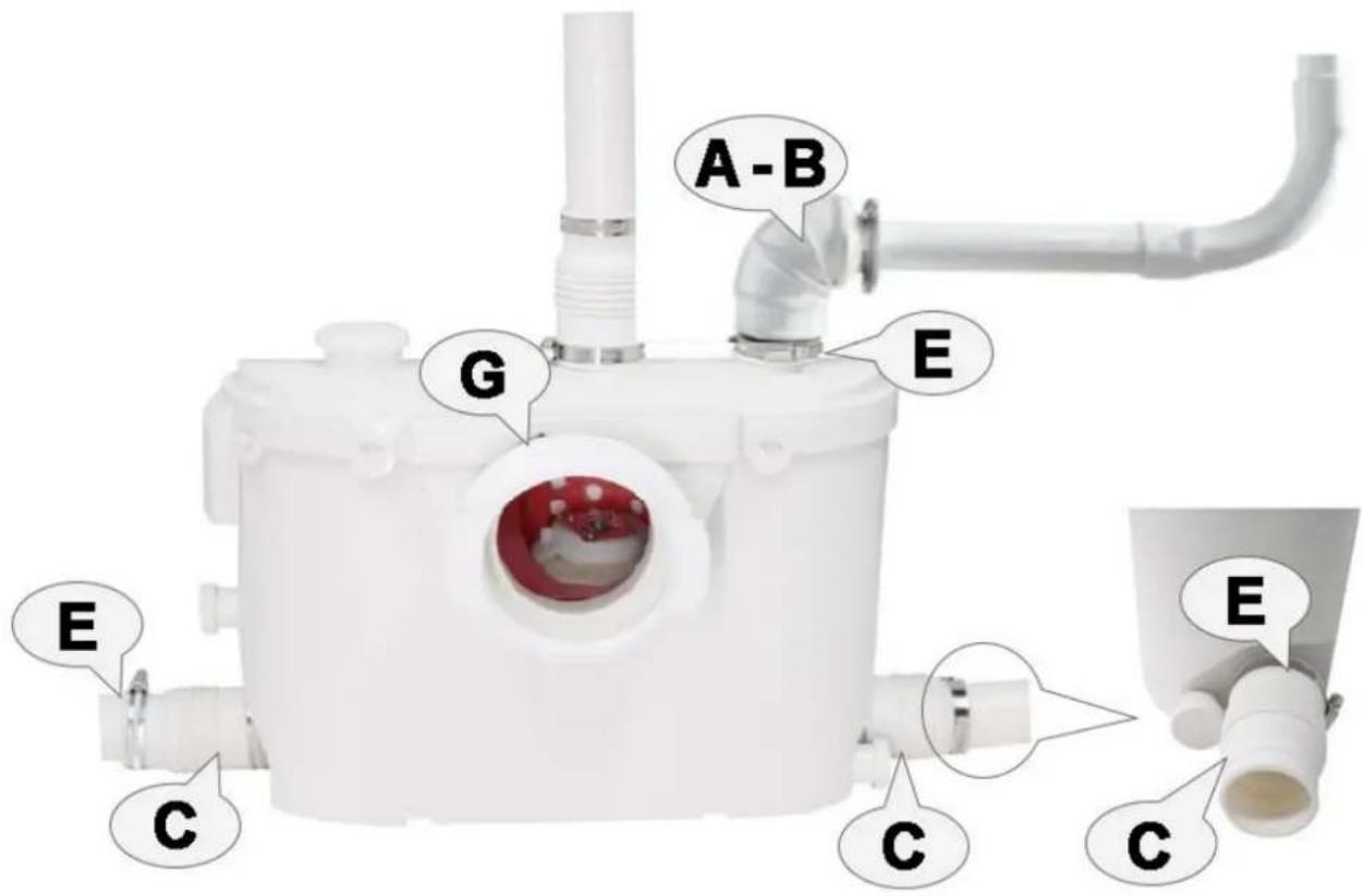
Then, install the check valve elbow (A-B) at the water drain hole and use the hoop (E) to fix it (32-50mm). The elbow can change direction freely to meet different customers' installation requirements.
- The elbow of the water drain hole can connect to PVC hard pipeline or metal pipe with diameter 22mm, 32mm, or 40mm. Please don't use flexible or soft pipes, because those pipes may deform over time and cause water leakage. Don't use a water drainage pipeline with diameter exceeding 40mm; otherwise, not only will the sewage not drain properly, but it will also affect the product's working life.
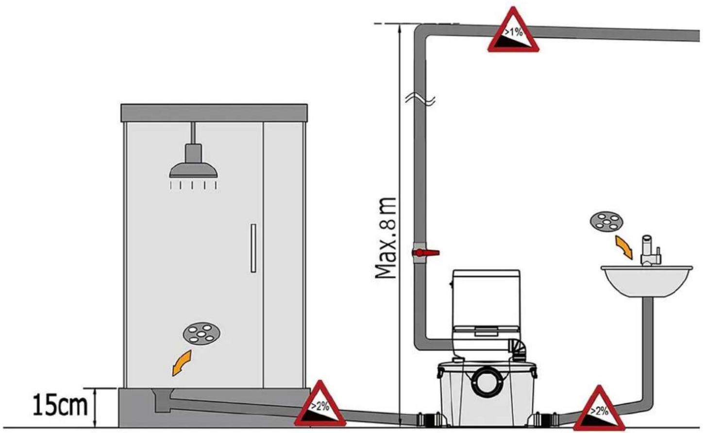
Otherwise, this will cause water not to drain off and damage the product. If horizontal drainage is necessary, the length of horizontal water drainage cannot exceed 30cm.

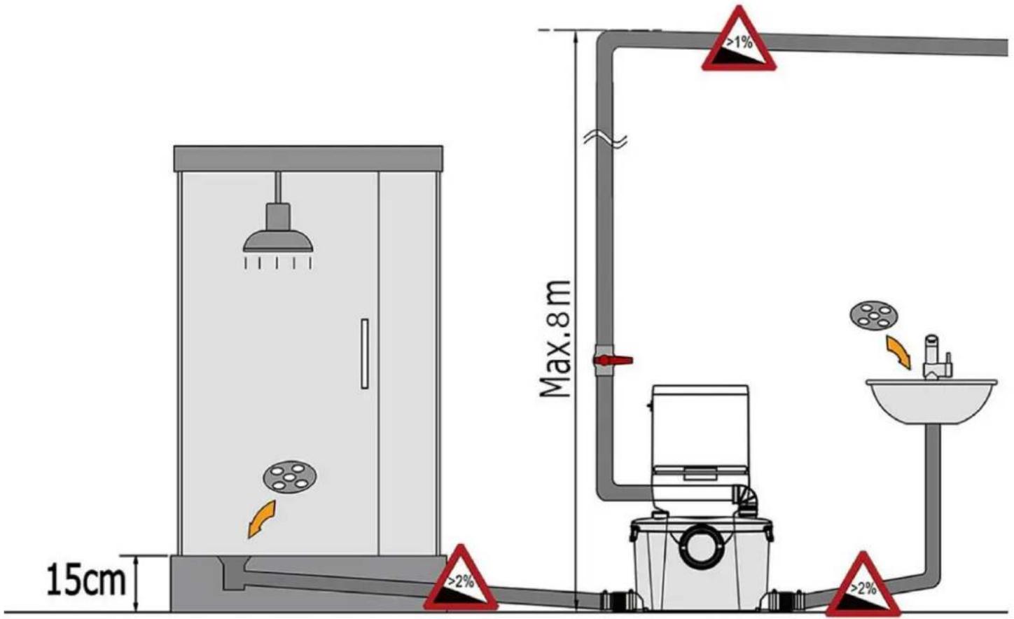
Then incline 2%-3% to lead the water drainage pipe to the main pipeline; otherwise, the sewage will return flow. Additionally, the elbow position of the PVC water pipe must use a 135° big elbow, not a 90° elbow; otherwise, it will affect the range.
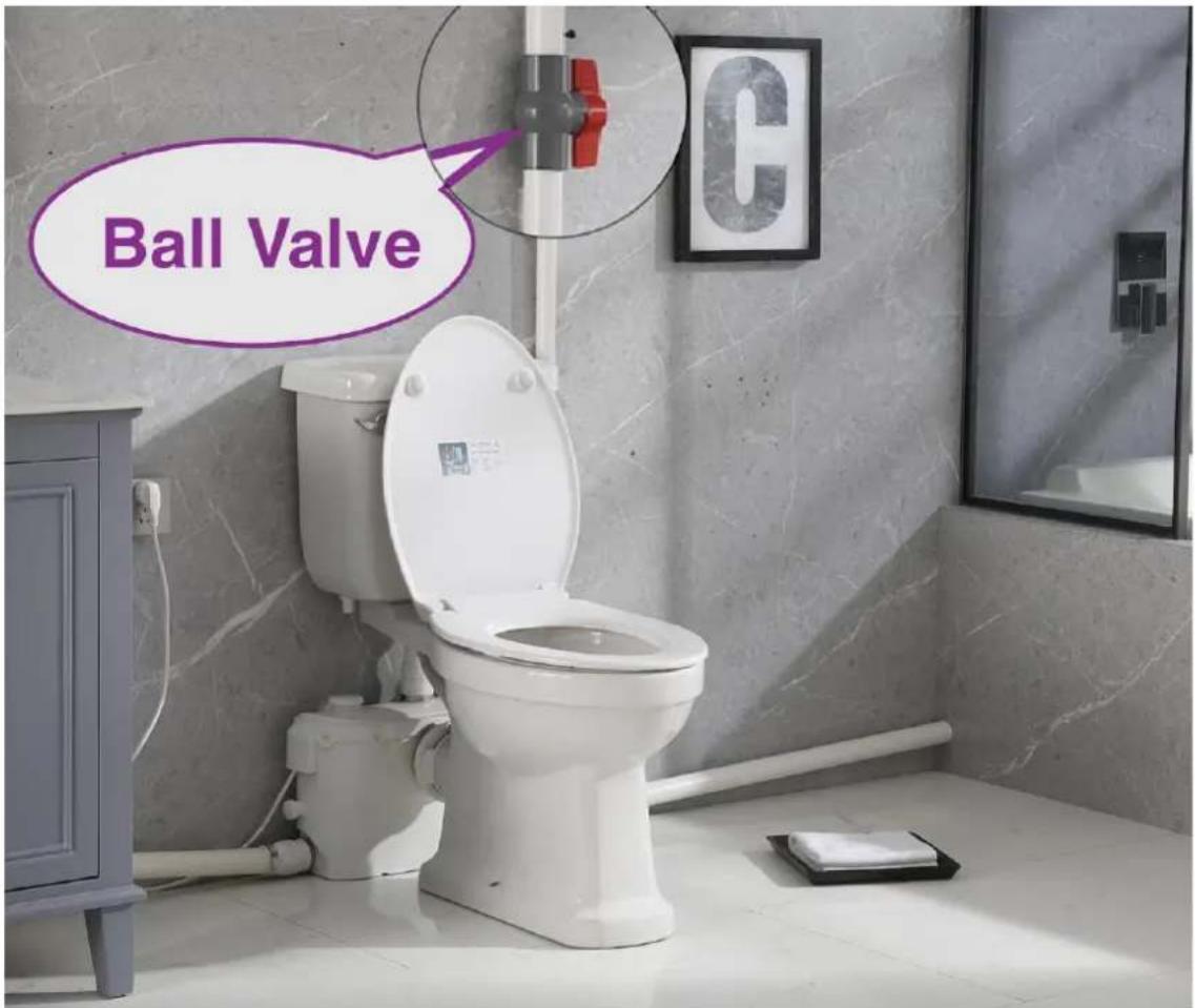
- Please install a ball valve (not provided) at a location close to the water outlet position, convenient to prevent sewage leakage when disassembling the water pump.
5. The second method of installing the water drainage check valve
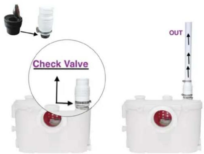
If the sewage pump is installed behind the wall, then the water tank of the toilet will not shield the drain hole. It is possible not to use the elbow (A-B). But, you must disassemble the black check valve from the accessories (A-B), then install it in the soft pipe (C). The diagram is shown below.
6-1. Installation of the connection pipe in the shower room
First, you can install a wooden rack or a shower base made of iron, or build a cement platform. This raises the shower room floor, and the drainage pipe between the sewage pump and the shower room should maintain a 3% incline to ensure that sewage flows smoothly from the shower room into the sewage pump.
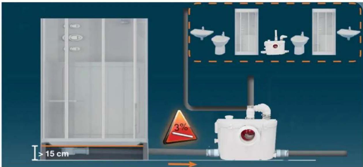
Attention: make sure the shower room chassis is raised at least 15 cm. This also depends on the distance from the shower room to the water pump.
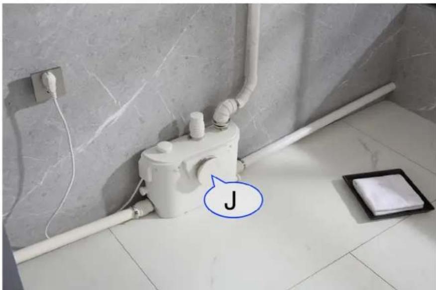
6-2. If the toilet is not connected, you can use the cover (J) to block the water inlet hole of the toilet, then use the hoop (G) to fix the toilet. Then only connect the water groove, shower room, and washing machine.
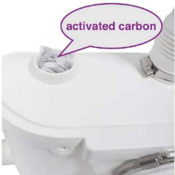
7. Activated carbon deodorization device
This product includes an activated carbon package with deodorizing function. You can insert the whole carbon package or use carbon powder. It is recommended to replace it once a year.
8. Connection to electrical supply
All wiring should be in accordance with the applicable electrical code in your territory. The macerating system requires a single-phase 110-volt to 120-volt supply. When installed in a bathroom, the receptacle should be 40 inches (1 m) away (in a straight line) from a shower or bathtub. Connect only to a receptacle protected by a ground fault circuit interrupter (GFCI).
Warning: risk of electric shock. This pump is supplied with a grounding conductor and a grounding-type attachment plug to reduce the risk of electrical shock. Be certain that it is connected only to a properly grounded-type receptacle.
9. Cautionary notes:
9-1. The normal application of FLOLUXURY macerating units is limited to the disposal of human waste, toilet paper, and water. The FLOLUXURY-500 is designed for family use only and cannot accept the disposal of sanitary items such as condoms, tampons, sanitary pads, and cotton swabs.
9-2. Do not discharge any acids, alkaloids, solvents, paint, paint strippers, food waste, plastic bags, metal such as nails, hairpins, wood, building materials, kitty litter, or anything that could halt, damage, or corrode the unit. Disregarding the above might damage the macerating unit.
Do not hang bleach blocks or hydrochloride cleaners in the toilet tank. These solutions have been shown to deteriorate the plastic and neoprene components of the flush and fill valves and may cause leaks. In the event of a power loss, do not use the toilet or any other sanitary fixture connected to the macerating unit, as it will not work until the power is restored.
The toilet works as a conventional flushing toilet and needs no maintenance in normal use. However, there is nothing wrong with cleaning out the macerating unit once a year. Do not use bleach (be careful not to let water enter the electrical cord opening).
The macerating unit starts automatically once the toilet is flushed or the bath, shower, hand basin, etc. discharge, and ceases operation once the contents have been pumped away.
Whenever the unit is not to be used for long periods of time (vacation, power failure, maintenance, etc.), turn off the water supply to the tank and flush the unit to evacuate the water. No leakage into the bowl should ever be permitted from the tank.
In areas prone to freezing, the total system must be properly winterized. This includes draining all pipes, the toilet tank and bowl, and the macerating tank. The macerating system is simple to winterize. Pour a jug of plumber's anti-freeze into the tank and flush the toilet. This will cause the macerating unit to activate and all remaining water will be replaced by plumber's anti-freeze. No parts or labor are warranted when a breakdown occurs due to freezing.
Ensure that there are no faucets left open. Drops will eventually fill up the pump and the resultant repeated start-stop of the motor may heat
up to such an extent that the thermal overload switch may eventually operate and automatically stop the motor, thus possibly causing a flood.
10. DISASSEMBLY FOR LITTLE INTERVENTION
As the unit is connected to the water and electrical supply, it is important to check that the following actions have been taken before removing the unit:
10-1. If possible, close off the water supply to the tank and close the ball or gate valve on the outlet pipe. 10-2. Pull the electrical cord out of the receptacle before removing the unit.
10-3. Empty out as much water as possible from the toilet tank and the toilet bowl. 10-4. Disconnect toilet from unit. Remove toilet bowl and set aside against a wall to prevent it from tipping over.
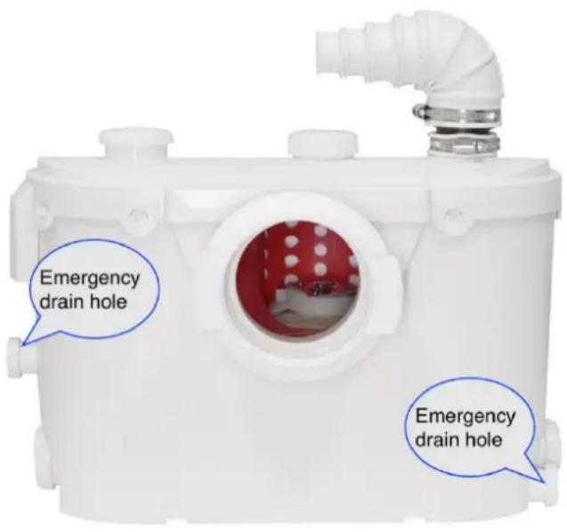
FloLuxury-500 has one patent design, that is the emergency drain hole. When your water pump needs maintenance, you can open the emergency drain hole to completely drain the sewage in the water pump, then disassemble the water pump from the back of the toilet. Your toilet room will not be out of order after having the emergency drain hole when the water pump needs maintenance.
10-5. The use of a dry/wet type vacuum cleaner might assist you greatly in removing the residual water in the bowl or macerating unit. 10-6. When you have to remove the macerating unit, carefully disconnect the inlet drainpipes (there might be residual water inside).
10-7. Side inlet valves clogged: remove the sleeves and use a screwdriver to free or clean the rubber flap if necessary.
10-8. Do not immerse the unit totally in water. Do not let water enter the electrical cord entrance opening.
10-9. When replacing the lid, grease the rubber gasket lightly with soapy water or dishwasher liquid. (Do not use Vaseline as this may expand the neoprene materials). The gasket must be inside the lid first. Start by pushing the lid down at the cord side first, then work your way around and tap on the lid with a rubber mallet or block.

CAUTION: Changes or modifications not expressly approved by the party responsible for compliance could void the user's authority to operate the equipment!
This device complies with Part 15 of the FCC Rules. Operation is subject to the following two conditions:
1) This product may cause harmful interference. 2) This product must accept any interference received, including interference that may cause undesired operation.
WARNING: Changes or modifications to this product not expressly approved by the party responsible for compliance could void the user's authority to operate the product.
Note: This product has been tested and found to comply with the limits for a Class B digital device pursuant to Part 15 of the FCC Rules. These limits are designed to provide reasonable protection against harmful interference in a residential installation.
This product generates, uses and can radiate radio frequency energy, and if not installed and used in accordance with the instructions, may cause harmful interference to radio communications. However, there is no guarantee that interference will not occur in a particular installation. If this product does cause harmful interference to radio or television reception, which can be determined by turning the product off and on, the user is encouraged to try to correct the interference by one or more of the following measures.
Reorient or relocate the receiving antenna.
- Increase the distance between the product and receiver. Connect the product to an outlet on a circuit different from that to which the receiver is connected.
- Consult the dealer or an experienced radio/TV technician for assistance.

Correct Disposal
This product is subject to the provision of European Directive 2012/19/EU. The symbol showing a wheelie bin crossed through indicates that the product requires separate refuse collection in the European Union. This applies to the product and all accessories marked with this symbol. Products marked as such may not be discarded with normal domestic waste, but must be taken to a collection point for recycling electrical and electronic devices.
VEVOR®
TOUGH TOOLS, HALF PRICE
Technical Support and E-Warranty Certificate
www.vevor.com/support
VEVOR®
- vent hole (carbon filter)
- inlet sanitary fixture
- outlet discharge pipe
- inlet toilet
- inlet sanitary fixture
6. emergency outlet
- inlet sanitary fixture
8. emergency outlet
| A-B x1
Elbow with Check Valve | C x3
coupling hose | D x1
Rubber Ring | E x6
Clamp 32-50mm |
| F x1
Activated carbon | G x2
Clamp 90-110mmx1
Clamp 100-120mmx1 | H x2
Blanking Plug | J x1
Lid |
Technical Support and E-Warranty Certificate
www.vevor.com/support
VEVOR®
- vent hole (carbon filter)
- inlet sanitary fixture
- outlet discharge pipe
- inlet toilet
- inlet sanitary fixture 6. emergency outlet
- inlet sanitary fixture 8. emergency outlet
3. Accessories list
| A-B x1
Elbow with Check Valve | C x3
coupling hose | D x1
Rubber Ring | E x6
Clamp 32-50mm |
| F x1
Activated carbon | G x2
Clamp 90-110mmx1
Clamp 100-120mmx1 | H x2
Blanking Plug | J x1
Lid |
freely. To meet different customer's installation
Technical Support and E-Warranty Certificate
www.vevor.com/support
VEVOR®
- vent hole ( carbon filter )
- inlet sanitary fixture
- outlet discharge pipe
- inlet toilet
- inlet sanitary fixture
6. emergency outlet
- inlet sanitary fixture
8. emergency outlet
| A-B x1
Elbow with Check Valve | C x3
coupling hose | D x1
Rubber Ring | E x6
Clamp 32-50mm |
| F x1
Activated carbon | G x2
Clamp 90-110mmx1
Clamp 100-120mmx1 | H x2
Blanking Plug | J x1
Lid |
Technical Support and E-Warranty Certificate
www.vevor.com/support
VEVOR®
- vent hole (carbon filter)
- inlet sanitary fixture
- outlet discharge pipe
- inlet toilet
- inlet sanitary fixture
6. emergency outlet
- inlet sanitary fixture
8. Emergency outlet
| A-B x1
Elbow with Check Valve | C x3
coupling hose | D x1
Rubber Ring | E x6
Clamp 32-50mm |
| F x1
Activated carbon | G x2
Clamp 90-110mmx1
Clamp 100-120mmx1 | H x2
Blanking Plug | J x1
Lid |
Technical Support and E-Warranty Certificate
www.vevor.com/support
VEVOR®
NEED HELP? CONTACT US!
- Vent hole (carbon filter)
- Inlet sanitary fixture
- Outlet discharge pipe
- Inlet toilet
- Inlet sanitary fixture
6. emergency outlet
- inlet sanitary fixture
8. emergency outlet
3. List of accessories
| A-B x1
Elbow with Check Valve | C x3
coupling hose | D x1
Rubber Ring | E x6
Clamp 32-50mm |
| F x1
Activated carbon | G x2
Clamp 90-110mmx1
Clamp 100-120mmx1 | H x2
Blanking Plug | J x1
Lid |
replaced by plumber's anti-freeze. No parts or labour are warranted
Technical Support and E-Warranty Certificate
www.vevor.com/support
VEVOR®
Technical support and e-warranty certificate www.vevor.com/support
MACERATOR PUMP
USER MANUAL
MODEL: FLO500-BE
- vent hole (carbon filter)
- inlet sanitary fixture
- outlet discharge pipe
- inlet toilet
- inlet sanitary fixture 6. emergency outlet
- inlet sanitary fixture 8. emergency outlet
3. Accessory list
| A-B x1
Elbow with Check Valve | C x3
coupling hose | D x1
Rubber Ring | E x6
Clamp 32-50mm |
| F x1
Activated carbon | G x2
Clamp 90-110mmx1
Clamp 100-120mmx1 | H x2
Blanking Plug | J x1
Lid |
freely. To meet different customer's installation
Technical Support and E-Warranty Certificate
www.vevor.com/support
VEVOR®
NEED HELP? CONTACT US!
- Installation (diagram)
- vent hole (carbon filter)
- inlet sanitary fixture
- outlet discharge pipe
- inlet toilet
- inlet sanitary fixture 6. emergency outlet
- inlet sanitary fixture 8. emergency outlet
3. Accessories list
| A-B x1
Elbow with Check Valve | C x3
coupling hose | D x1
Rubber Ring | E x6
Clamp 32-50mm |
| F x1
Activated carbon | G x2
Clamp 90-110mmx1
Clamp 100-120mmx1 | H x2
Blanking Plug | J x1
Lid |
Technical Support and E-Warranty Certificate
www.vevor.com/support