
7X 1244 - Car suspension Vevor - Free user manual and instructions
Find the device manual for free 7X 1244 Vevor in PDF.

| Brand | Vevor |
| Model | 7X1244 |
| Product Type | Airbag Suspension Kit |
| Applications | Ford F250/F350 2WD and 4WD (1999-2004, 2008-2010) |
| Rated Load | 5000 lbs |
| Operating Pressure | 5 to 100 psi (max 150 psi) |
| Minimum Operating Pressure | 5 psi |
| Maximum Inflation Pressure | 150 psi |
| Air Fitting Type | 1/4" Push-to-Connect Fitting |
| Inflation Valve | 1/4" Schrader Valve |
| Materials | Steel, Rubber (airbags) |
| Kit Contents | 2 air springs, brackets, hoses, fittings, straps, bolts, nuts, etc. |
| Maintenance | Check air pressure weekly |
| Safety | Do not exceed vehicle GVWR |
| Warranty | Technical support and electronic warranty certificate at www.vevor.com/support |
| Manufacturer | Shanghaimuxinmuyeyouxiangongsi, Shanghai, China |
| Australia Importer | SIHAO PTY LTD, NSW |
| USA Importer | Sanven Technology Ltd., Rancho Cucamonga, CA |
| UK Importer | YH CONSULTING LIMITED, Frankfurt am Main (Germany) |
Frequently Asked Questions - 7X 1244 Vevor
User questions about 7X 1244 Vevor
0 question about this device. Answer the ones you know or ask your own.
Ask a new question about this device
Download the instructions for your Car suspension in PDF format for free! Find your manual 7X 1244 - Vevor and take your electronic device back in hand. On this page are published all the documents necessary for the use of your device. 7X 1244 by Vevor.
USER MANUAL 7X 1244 Vevor
Technical Support and E-Warranty Certificate www.vevor.com/support
Air Bag Suspension Kit
MODEL: 7X1244
We continue to be committed to provide you tools with competitive price.
"Save Half", "Half Price" or any other similar expressions used by us only represents an estimate of savings you might benefit from buying certain tools with us compared to the major top brands and does not necessarily mean to cover all categories of tools offered by us. You are kindly reminded to verify carefully when you are placing an order with us if you are actually saving half in comparison with the top major brands.
VEVOR®
TOUGH TOOLS, HALF PRICE
Air Bag Suspension Kit
MODEL: 7X1244
NEED HELP? CONTACT US!
Have product questions? Need technical support? Please feel free to contact us:
Technical Support and E-Warranty Certificate www.vevor.com/support
This is the original instruction, please read all manual instructions carefully before operating. VEVOR reserves a clear interpretation of our user manual. The appearance of the product shall be subject to the product you received. Please forgive us that we won't inform you again if there are any technology or software updates on our product.
SECURITY & WARNINGS
Thank you for purchasing the 7X 1244 Kit! Please kindly be advised to read the instructions carefully before installing the air spring kit.
Please take safety precautions accordingly during installation.
The installation instructions are based on the left side or based on the driver's side of the vehicle, and the structure on the right side can refer to the same method on the left side.

The retrofit kit you purchased is a single valve inflation system.
Please note that the air spring will bend and expand under working
conditions. Ensure there is enough space for it to work properly and avoid friction between the air spring and other chassis parts.
PARAMETER LIST
| Model | standard |
| Adapted models | 1999-2004 Ford F250/F350 2WD&4WD2008-2010 Ford F250/F350 2WD&4WD |
| rated load (lbs) | 5000 |
| Use the pressure (psi) | 5-100 |
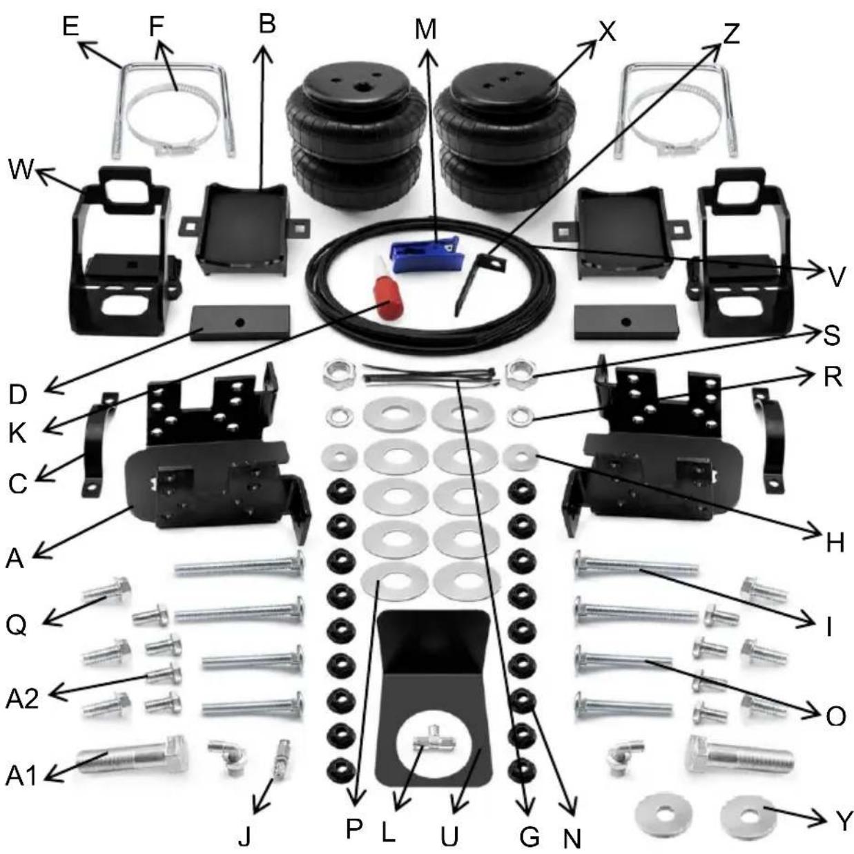
PARTS LIST
| ITEM | DESCRIPTION | QUANTITY | ITEM | DESCRIPTION | QUANTITY |
| A | Spacer | 2 | Q | 3/8"-16 x 3/4" FLANGED HEX BOLT | 6 |
| B | Saddle Bracket | 2 | R | LOC KWASHER | 2 |
| C | Axle Straps | 2 | S | 3/4" HEX NUT | 2 |
| D | Flat steel | 2 | T | Instructions | 1 |
| E | U-shaped bolt | 2 | U | Heat Shield | 1 |
| F | Metal Cable Zip Tie | 2 | O | CARRIAGE BOLT, 3/8-16UNC L=58mm | 4 |
| G | Tie straps | 10 | P | Flat cushion | 8 |
| H | Flat cushion | 2 | V | 1/4" DOT Air Hose | 1 |
| I | CARRIAGE BOLT, 3/8-16UNC L=70mm | 4 | W | Upper Bracket | 2 |
| J | 1/4" Schrader valve | 1 | X | Airbags | 2 |
| K | Thread adhesive | 1 | Y | Flat cushion | 2 |
| L | 1/4" T- Valve | 1 | Z | L-shaped steel | 1 |
| M | Tracheal scissors | 1 | A1 | 3/4"-16 X 3"BOLT | 2 |
| N | 3/8"-16 FLANGED NUT | 18 | A2 | 3/8"-16 BOLT | 8 |
IMPORTANT!
For your own safety and in aim to prevent possible damage to the vehicle, don't exceed the maximum load recommended by the vehicle manufacturer. Your air bag helper springs are rated at a maximuminflation pressure of 150 PSI. You are allowed to carry a greater load on some vehicles with this pressure.
It is best to have your vehicle weighed once it is completely loaded and compare that weight to the maximum allowed.
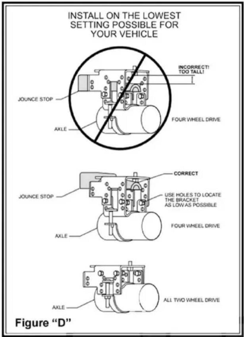
! IMPORTANT: INSTALL ON THE LOWEST SETTING POSSIBLE FOR YOUR VEHICLE
FAILURE TO DO SO CAN RESULT IN DAMAGED BRACKETS AND CAN VOID YOUR WARRANTY
* 4 3/8 x 1/2 x 1 1/2 block supplied to use if collard is

STEP 1- PREPARE THE VEHICLE
Place the truck on a solid level surface. Remove the negative battery cable.
Take necessary safety precautions such as using wheel chocks when working on your truck. Such as using wheel chocks when working on your truck. Remove the nut holding the fuel line retaining clip.
Rotate the retaining clip 90 degrees with the stud facing down. Install the relocation bracket with the nut previously removed. Next, fasten the retaining clip to the relocation bracket using a 5/16"-24x3/4" bolt and 5/16"-24 flange nut. Your truck is equipped with jounce bumpers attached to the frame directly above the axle. Remove these bumpers by unbolting from the inside of the frame flange. These bumpers will not be reused with this kit. Please save the collar as it will be reused in Step 2.
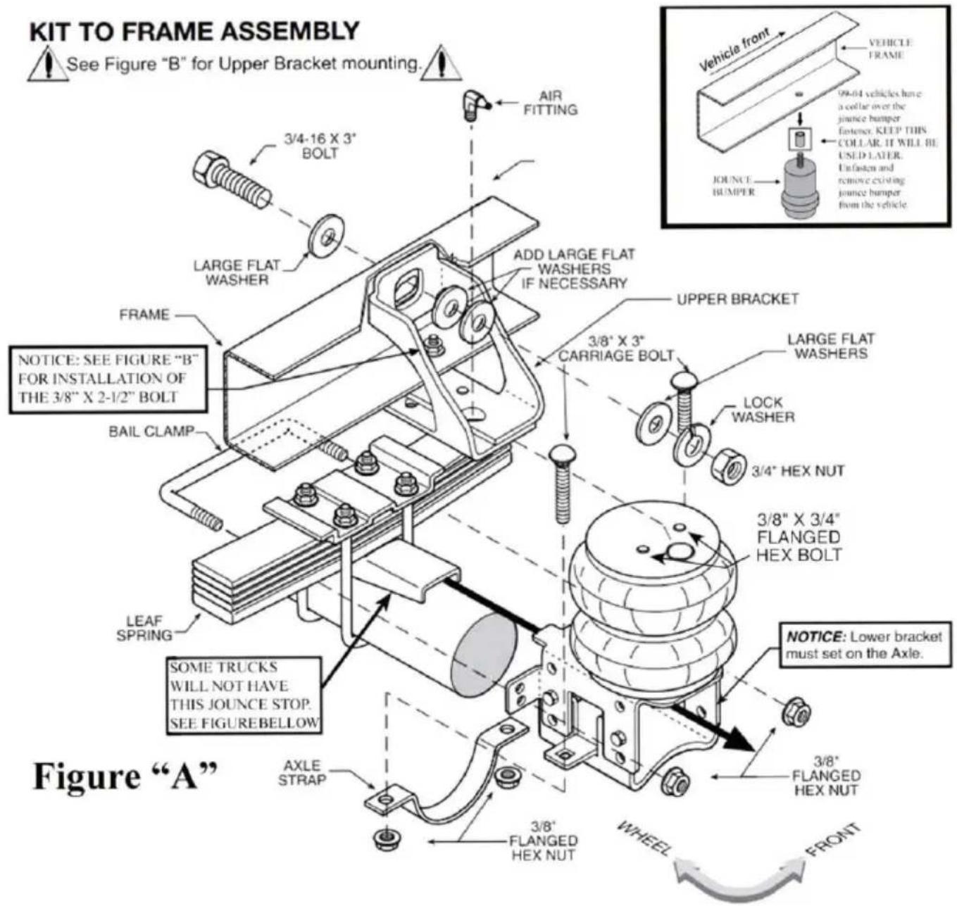
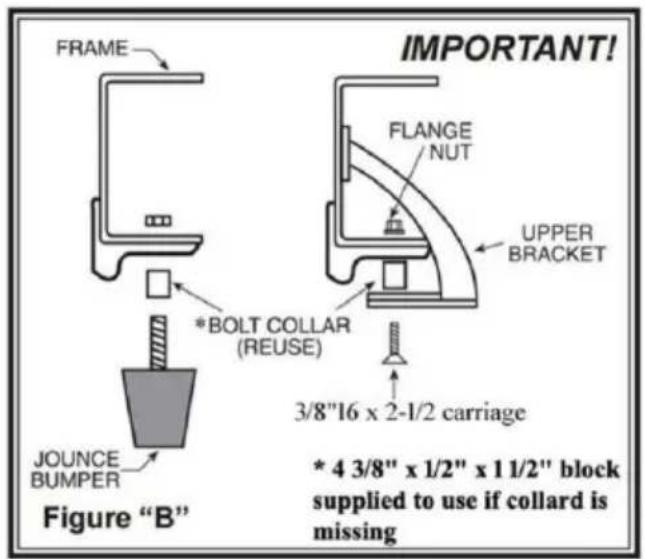
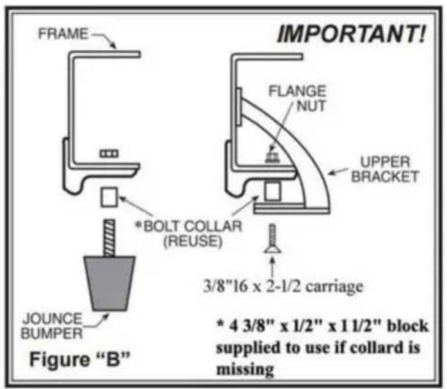
STEP 2- UPPER BRACKET INSTALLATION
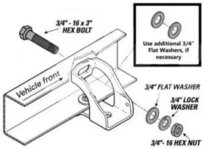
Make sure that no part of the vehicle's wiring will be pinched between the upper bracket and the frame. At this time, the collar that was on the jounce bumper will be reused. Insert the collar into the original hole on the frame. Put the upper bracket in place (to hold the collar) while you insert the 3/8"-16 x 2-1/2" carriage bolt into the upper bracket and collar.
See Figure "B". Secure the 3/8"-16
carriage bolt with a 3/8" large flat washer and 3/8"-16flange nut finger tight. Hold the upper bracket tight against the bottom of the frame. If the bracket appears to be level with the upper part of the bracket rests against the inside of the frame, install the 3/4"-16x3" bolt through the frame railand upper bracket. If the top of the bracket does not set level, install some of the large 3/4" flat washers between the bracket and the inside of the frame rail. If you have existing hitch hardware, the 3/4" bolt should be long enough to extend through the upper bracket, truck frame and hitch brackets. Be sure to install at least one of the large flat washers and the 3/4" lock washer before installing the 3/4"-16 hex nut onto the bolt. After you have installed the upper bracket as level as possible, tighten the 3/8"-16x2 1/2" flat head bolt in the bottom of the frame, then tighten the 3/4"-16 x 3" bolt through the side of the frame. The emergency brake cable will have to be
tie-wrapped out of the way using the hole provided in the upper bracket. See Figure "A".
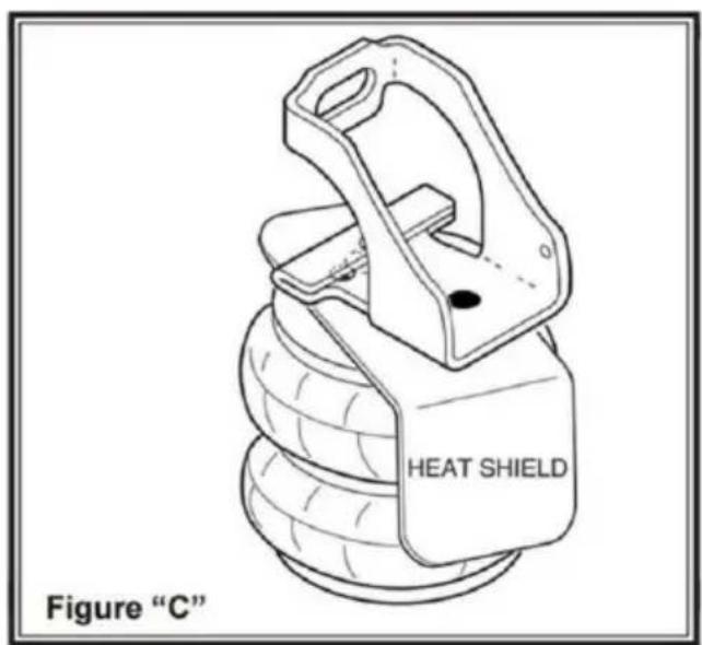
STEP 3- AIR SPRING INSTALLATION
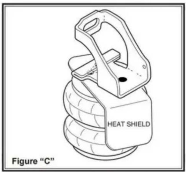
The heat shield will be used on the exhaust side of the truck only. It is placed between the upper bracket and the top of the air spring. See Figure "B". When the air spring is in place and properly aligned, using two 3/8"-16 x 3/4" flanged hex bolts attach the bag to the upper bracket. On the right side, align the heat shield before tightening the flanged hex bolts on the air spring. Make sure the heat shield will not interfere with the normal operation of the air spring or the vehicle's suspension. Do not position the face of the heat shield directly over the axle, as it may contact the axle on full suspension compression. Next, install the air fitting into the stud of the air spring. Tighten the air fitting securely to engage the semi-permanent thread sealant.
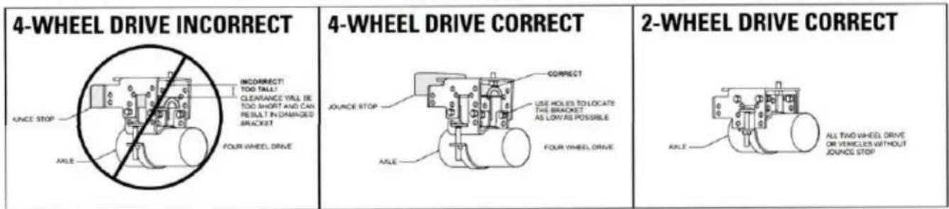
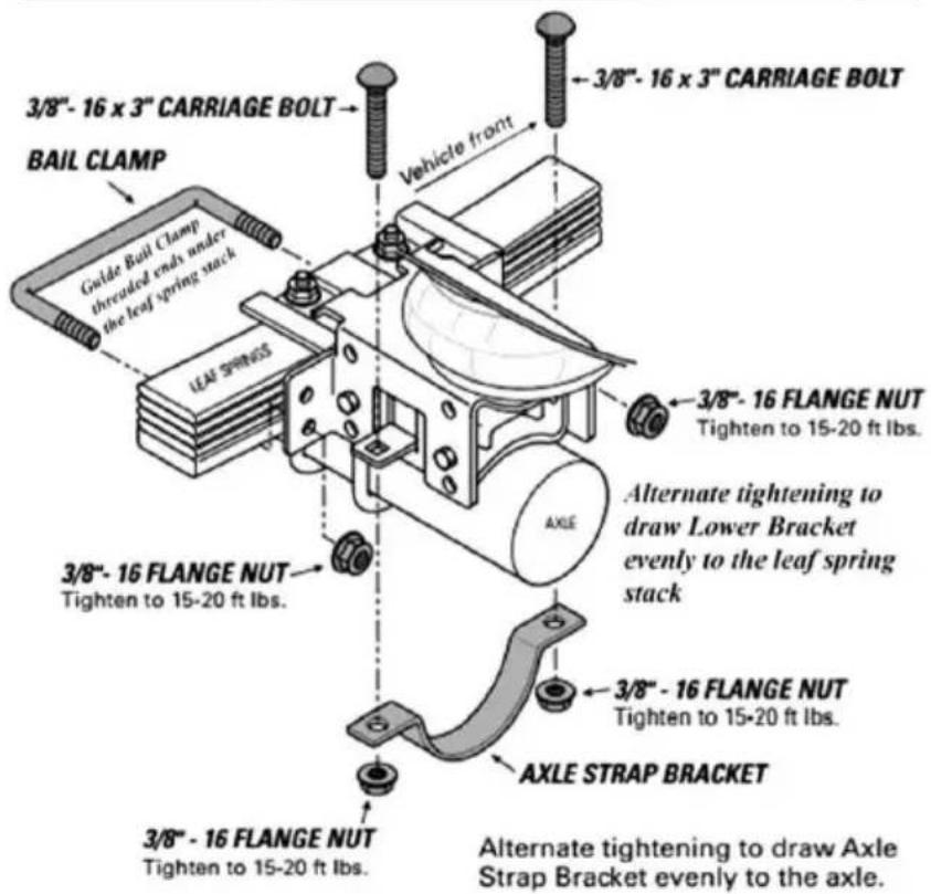
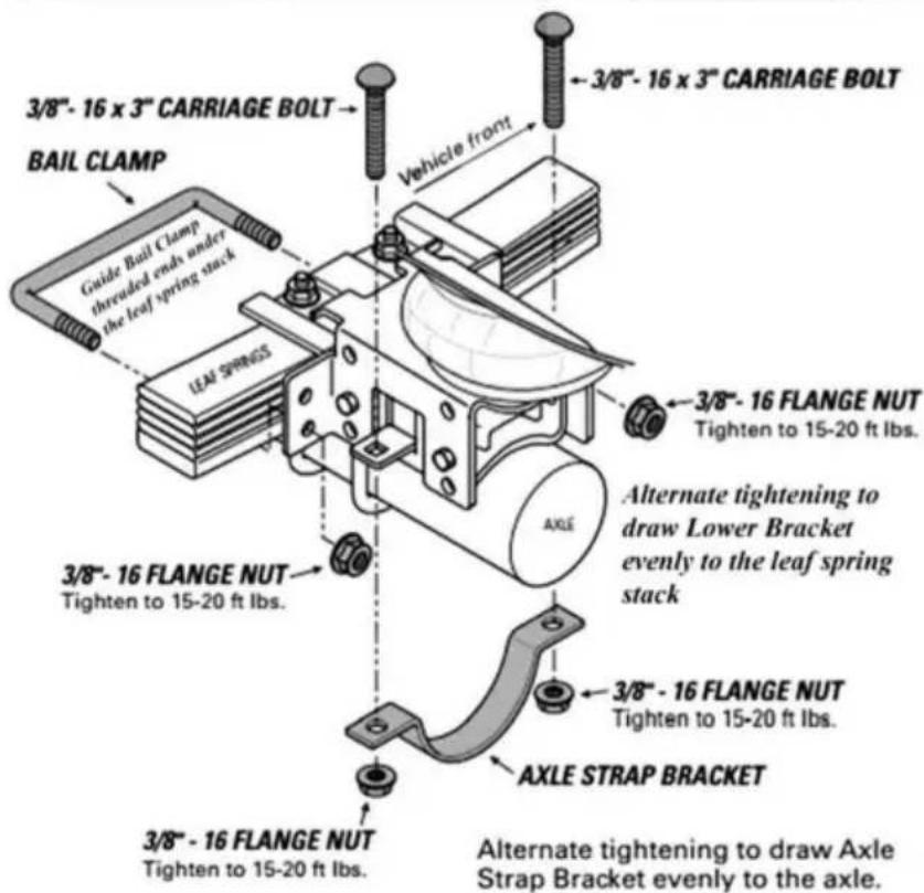
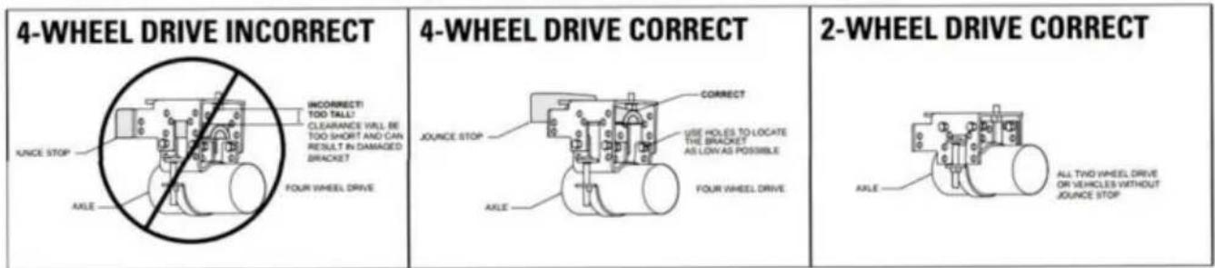
STEP 4- LOWER BRACKET INSTALLATION
Four-wheel drive trucks will have a cast-iron jounce stop as shown in Figures "A" and "C". If this jounce stop is present, the height setting of the lower bracket assembly needs to be just above the jounce stop (to clear the head of the bolt in the bottom of the air spring). On two-wheel-drive trucks as semble the lower assembly to the shortest setting. See Figure "D". The lower bracket assembly should be installed on the lowest setting possible for the truck. See Figure "D". The saddle and lower bracket are bolted together using four 3/8"-16x1" bolts and flange nuts to make up the lower bracket assembly. When the assembly is bolted together at the proper height, install the 3/8"-16 x 3/4" flange bolt through the forward hole on the lower bracket into the bottom of the air spring and tighten. Place the lower bracket assembly against the leaf spring stack making sure that the top of the lower bracket fits in between the axle U-bolts. Place the bail clamp around the axle block and install the 3/8"-16 flange nuts onto the bail clamp and tighten. Insert the carriage bolts through the square holes on the lower bracket assembly being careful not the chaff or pinch the brake lines on the axle. Next push the axle strap onto the bottom of the axle and through the carriage bolts. When the 3/8"-16 flange nuts are tightened, they will draw the axle strap into place. To raise the vehicle by theframe, deflate both air springs completely.
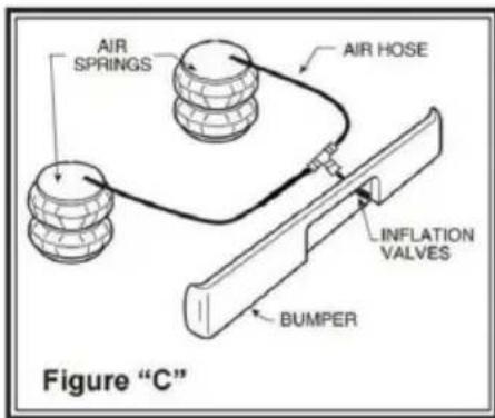
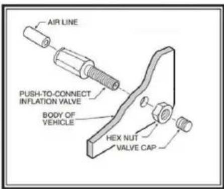
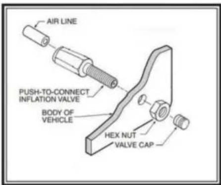
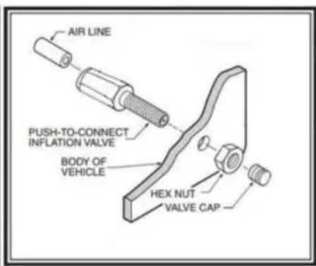
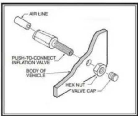
STEP 5- INSTALL THE AIR LINE AND INFLATION VALVE
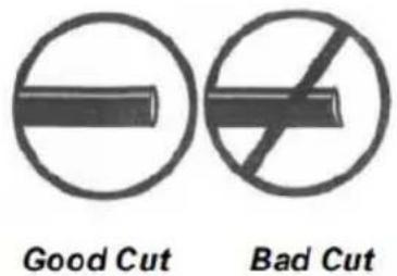
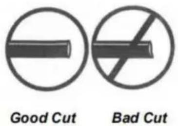
Uncoil the air tubing and cut it in two equal lengths. DO NOT FOLD OR KINK THE TUBING. Make the cut as square as possible, using a hose cutter. Insert one end of the tubing into the push-to-connect fitting installed in the top of the air helper spring. Select a location on the vehicle for the air inflation valve. The location can be on the bumper or the body of the vehicle, as long as it is in a protected location so the valve will not be damaged, but still maintain accessibility for the air chuck, see Figure "E". Drill a 5/16" hole and install the air inflation valve. Run the tubings from the air helper spring to the tee and to the valve, routing it to avoid direct heat from the engine, exhaust pipe, and away from sharp edges. Use thermal sleeves if the hose is near these conditions. The air line tubings should not be bent or curved shape as it may buckle. Secure the tubing in place with the nylon ties provided. Push the end of the airline tubing into the inflation valve, see Figure "C".
Too much air pressure in the air springs will result in a firmer ride, while too little air pressure will allow the air springs to bottom out over rough conditions. Too little air pressure will also not provide the improvement in handling that is possible. TO PREVENT POSSIBLE DAMAGE MAINTAIN A MINIMUM OF 5 psi IN THE AIR SPRINGS AT ALLTIMES.
Minimum Pressure 5 psi Normal Air Pressure 60-80 psi Max Pressure 150 psi (under full load) Burst Pressure 320 psi
SQUARE CUT WILL ENSURE AGAINST LEAKS. DON'T USE WIRE CUTTERS OR SCISSORS TO CUT THE AIR LINE. THESE MAY FLATTEN OR CRIMP THE AIR LINE CAUSING IT TO LEAK AROUND THE O-RING SEAL INSIDE THE ELBOW
FITTING.
GUIDE LINE FOR ADDING AIR
- Start with the vehicle level or slightly above.
- When In doubt, always add air.
- If the front of the vehicle
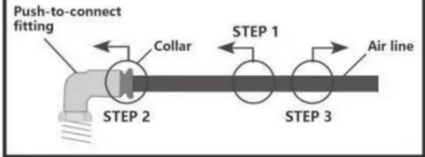
PUSH-TO-CONNECT (PTC) FITTINGS
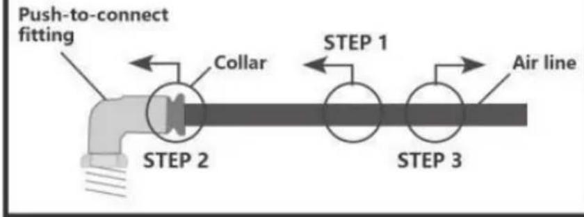
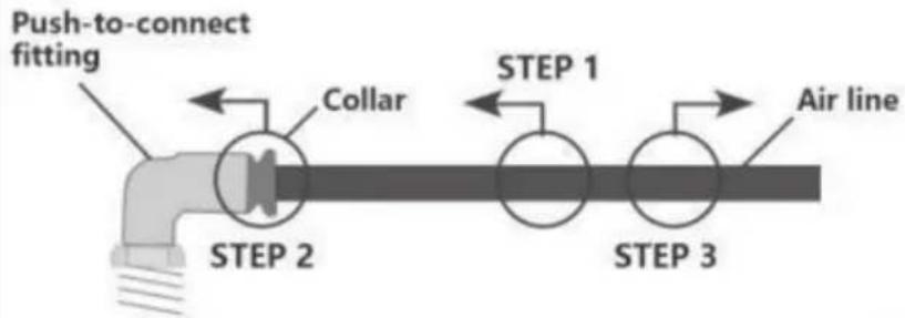
Air lines should be pushed into the push-to-connect fittings firmly, with a slight side-to-side rotational twist. Check the connection by pulling on each line to verify a robust connection.
To release the air line from the connection, first release all air from the system. Push in on the air line (step 1), push the collar in (step 2), and with the collar depressed, pull the air line out of the fitting (step 3).
dives while braking, increase the pressure Si the front air bag if equipped.
4. If it is ever suspected that the at bags have bottomed out Increase the pressure.
5. Adjust the pressure up and down to find the best ride.
6. It may be necessary to maintain different pressures on each side of the vehicle. Loads such as water, fuel, and appliances will cause the vehicle to be heavier on one side. As much as a 50 PSI difference is not uncommon. (additional schrader valves can be purchased)
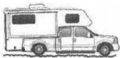
natural_image
Side view illustration of a vintage-style camper van (no text or symbols visible)Bottoming out
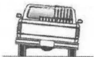
natural_image
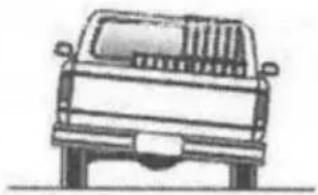
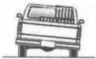
Front view line drawing of a pickup truck (no text or symbols)Unlevel
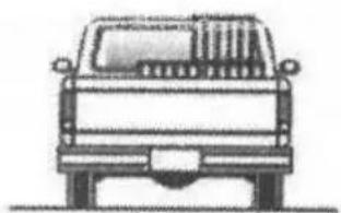
natural_image
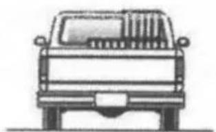
Front view line drawing of a pickup truck (no text or symbols)Level
By following the steps below, vehicle owners will obtain the longest life and best result from their air springs.
- Check the air pressure weekly.
-
Always maintain normal ride height.
-
If you develop an air leak in the system, use a soapy water solution (1 part dish soap. 4 parts water) to check all air fine connections and the Inflation valve core before deflating and removing the air spring.
-
When increasing load, always adjust the air pressure to maintain the normal ride height. Increase or decrease pressure from the system as necessary to attain normal ride height for optimal ride and handling. Remember that loads carried behind the aide (including tongue loads) require more levelling force (pressure) than those carried directly over the axle.

CAUTION
FOR YOUR SAFETY AND TO PREVENT POSSIBLE DAMAGE TO YOUR VEHICLE, DO NOT EXCEED THE MAXIMUM
GROSS VEHICLE WEIGHT RATING (GVWR). AS INDICATED BY THE VEHICLE MANUFACTURER.
IMPORTANT SAFETY NOTICE :
The installation of this kit does not alter the Gross Vehicle Weight Rating (GVWR) or payload of the vehicle. Check your vehicle's owner's manual and do not exceed the maximum load listed lot your vehicle.
Gross Vehicle Weight Paling: The maximum allowable weight of the fully-loaded vehicle (including passengers and cargo) This number — along with other weight limits. as well as tire, rim size and inflation pressure data — Is shown on the vehicle's Safely Compliance Certification Label.
Manufacturer: Shanghaimuxinmuyeyouxiangongsi
Address: Shuangchenglu 803nong11hao1602A-1609shi, baoshanqu, shanghai 200000 CN.
Imported to AUS: SIHAO PTY LTD. 1 ROKEVA STREETEASTWOOD NSW 2122 Australia
Imported to USA: Sanven Technology Ltd. Suite 250, 9166 Anaheim Place, Rancho Cucamonga, CA 91730
| UK | REP |
YH CONSULTING LIMITED.
C/O YH Consulting Limited Office 147,
Centurion House, London Road,
Staines-upon-Thames, Surrey, TW18 4AX
| EC | REP |
E-CrossStu GmbH
Mainzer Landstr.69,
60329 Frankfurt am Main.
VEVOR®
TOUGH TOOLS, HALF PRICE
Technical Support and E-Warranty Certificate
www.vevor.com/support
VEVOR®
TOUGH TOOLS, HALF PRICE
natural_image
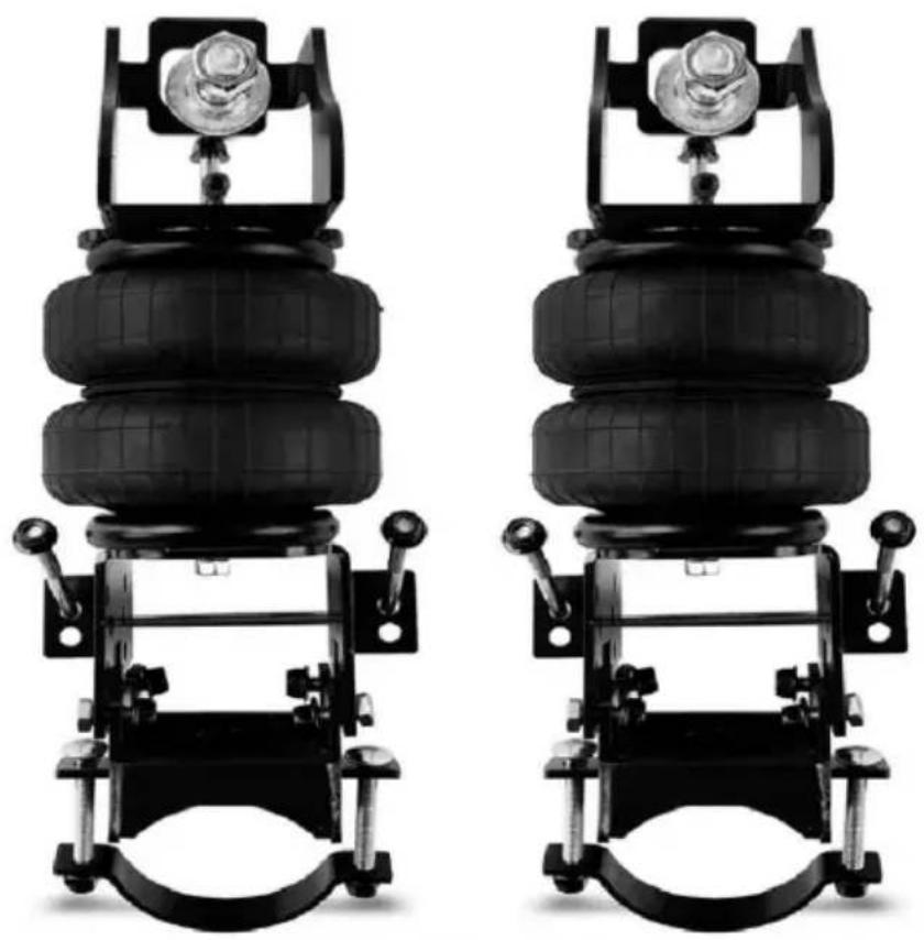
Two black automotive tire suspension systems with mounting brackets and a central tire assembly (no text or symbols visible)BESOIN D'AIDE? CONTACTEZ-NOUS!
! IMPORTANT: INSTALL ON THE LOWEST SETTING POSSIBLE FOR YOUR VEHICLE
FAILURE TO DO SO CAN RESULT IN DAMAGED BRACKETS AND CAN VOID YOUR WARRANTY

* 4 3/8 x 1/2 x 1 1/2 block supplied to use if collard is


ÉTAPE 1- PRÉPARER LE VÉHICULE


Minimum Pressure 5 psi Normal Air Pressure 60-80 psi Max Pressure 150 psi (under full load) Burst Pressure 320 psi

LORS DE LA COUPE OU DU COUPE DE LA CONDUITE D'AIR, UTILISEZ UN HOS COUPEUR, UNE LAME DE RASOIR OU UN COUTEAU AIGUISÉ. UN PROPRE,
UNE COUPE CARRÉ GARANTIRA CONTRE LES FUITES. N'UTILISEZ PAS DE COUPE-FIL OU CISEAUX POUR COUPER LA CONDUITE AÉRIENNE. CEUX-CI PEUVENT APLATIR OU FRIMER L'AIR CONDUITE PROVOQUANT UNE FUITE AUTOUR DU JOINT TORIQUE À L'INTÉRIEUR DU COUDE
RACCORD.
LIGNE DIRECTRICE POUR AJOUT D'AIR
Air lines should be pushed into the push-to-connect fittings firmly, with a slight side-to-side rotational twist. Check the connection by pulling on each line to verify a robust connection.
To release the air line from the connection, first release all air from the system. Push in on the air line (step 1), push the collar in (step 2), and with the collar depressed, pull the air line out of the fitting (step 3).

natural_image
Side profile illustration of a vintage-style camper van with a trailer and cabin (no text or symbols)Toucher le fond
natural_image
Front view line drawing of a pickup truck (no text or symbols)Unlevel
natural_image
Front view line drawing of a classic off-road vehicle (no text or symbols)Niveau
C/O YH Consulting Limited Bureau 147,
Maison Centurion, London Road,
Staines-upon-Thames, Surrey, TW18 4AX
| EC | REP |
E-CrossStu GmbH
Mainzer Landstr.69,
WICHTIG!
! IMPORTANT: INSTALL ON THE LOWEST SETTING POSSIBLE FOR YOUR VEHICLE
FAILURE TO DO SO CAN RESULT IN DAMAGED BRACKETS AND CAN VOID YOUR WARRANTY


* 4 3/8 x 1/2 x 1 1/2 block supplied to use if collard is


Minimum Pressure 5 psi Normal Air Pressure 60-80 psi Max Pressure 150 psi (under full load) Burst Pressure 320 psi

Air lines should be pushed into the push-to-connect fittings firmly, with a slight side-to-side rotational twist. Check the connection by pulling on each line to verify a robust connection.
To release the air line from the connection, first release all air from the system. Push in on the air line (step 1), push the collar in (step 2), and with the collar depressed, pull the air line out of the fitting (step 3).
natural_image
Side view line drawing of a compact camping vehicle (no text or symbols)natural_image
Front view line drawing of a pickup truck (no text or symbols)Uneben

natural_image
Front view line drawing of a classic off-road vehicle (no text or symbols)Ebene
C/O YH Consulting Limited Büro 147,
Centurion House, London Road,
Staines-upon-Thames, Surrey, TW18 4AX
| EC | REP |
E-CrossStu GmbH
Mainzer Landstr.69,
60329 Frankfurt am Main.
VEVOR®
TOUGH TOOLS, HALF PRICE
www.vevor.com/support
VEVOR®
TOUGH TOOLS, HALF PRICE
natural_image
Two identical black-and-white photo of a car tire suspension system with mounting brackets and a central valve (no text or symbols visible)HO BISOGNO DI AIUTO? CONTATTACI!
IMPORTANTE!
! IMPORTANT: INSTALL ON THE LOWEST SETTING POSSIBLE FOR YOUR VEHICLE
FAILURE TO DO SO CAN RESULT IN DAMAGED BRACKETS AND CAN VOID YOUR WARRANTY


* 4 3/8 x 1/2 x 1 1/2 block supplied to use if collard is

FASE 1- PREPARARE IL VEICOLO


Minimum Pressure 5 psi Normal Air Pressure 60-80 psi Max Pressure 150 psi (under full load) Burst Pressure 320 psi

QUANDO SI TAGLIA O RIFILARE LA LINEA DELL'ARIA, UTILIZZARE UN HOS
UN TAGLIERINO, UNA LAMA DI RASOIO O UN COLTELLO AFFILATO. UN PULITO,
IL TAGLIO SQUADRATO GARANTIRÀ CONTRO LE PERDITE. NON UTILIZZARE TAGLIAFILI O
FORBICI PER TAGLIARE LA LINEA ARIA. QUESTI POSSONO APPiattire o CRIMPARE L'ARIA
LINEA CHE PROVOCA UNA PERDITA INTORNO ALLA TENUTA O-RING ALL'INTERNO DEL GOMITO
MONTAGGIO.

LINEA GUIDA PER
AGGIUNTA DI ARIA
Air lines should be pushed into the push-to-connect fittings firmly, with a slight side-to-side rotational twist. Check the connection by pulling on each line to verify a robust connection.
To release the air line from the connection, first release all air from the system. Push in on the air line (step 1), push the collar in (step 2), and with the collar depressed, pull the air line out of the fitting (step 3).
natural_image
Side view line drawing of a compact camping vehicle (no text or symbols)Toccare il fondo
natural_image
Front view line drawing of a pickup truck (no text or symbols)Non livellato

natural_image
Front view line drawing of a classic off-road vehicle (no text or symbols)Livello
Importato in AUS: SIHAO PTY LTD. 1 ROKEVA STREETEASTWOOD NSW 2122Australia
C/O YH Consulting Limited Ufficio 147,
Casa del Centurione, London Road,
Staines-upon-Thames, Surrey, TW18 4AX
| EC | REP |
E-CrossStu GmbH
Mainzer Landstr.69,
natural_image
Two black automotive tire suspension systems with mounting brackets and a central tire assembly (no text or symbols visible)¡IMPORTANTE!
! IMPORTANT: INSTALL ON THE LOWEST SETTING POSSIBLE FOR YOUR VEHICLE
FAILURE TO DO SO CAN RESULT IN DAMAGED BRACKETS AND CAN VOID YOUR WARRANTY


* 4 3/8 x 1/2 x 1 1/2 block supplied to use if collard is


PASO 1- PREPARAR EL VEHÍCULO

Minimum Pressure 5 psi Normal Air Pressure 60-80 psi Max Pressure 150 psi (under full load) Burst Pressure 320 psi
AL CORTAR O RECORTAR LA LÍNEA DE AIRE, USE UNA HOS
CORTADOR, UNA HOJA DE NAVAJA O UN CUCHILLO AFILADO. UN LIMPIO,
PUSH-TO-CONNECT (PTC) FITTINGS
Air lines should be pushed into the push-to-connect fittings firmly, with a slight side-to-side rotational twist. Check the connection by pulling on each line to verify a robust connection.
To release the air line from the connection, first release all air from the system. Push in on the air line (step 1), push the collar in (step 2), and with the collar depressed, pull the air line out of the fitting (step 3).
LÍNEA GUÍA PARA AÑADIR AIRE
natural_image
Side view line drawing of a compact camping vehicle (no text or symbols)Tocando fondo

natural_image
Front view line drawing of a pickup truck (no text or symbols)Desnivelar

natural_image
Front view line drawing of a classic pickup truck (no text or symbols)Nivel
Casa Centurión, London Road,
Staines upon Thames, Surrey, TW18 4AX
| EC | REP |
E-CrossStu GmbH
Mainzer Landstr.69,
natural_image
Mechanical assembly with black tire and clamping bracket (no visible text or symbols)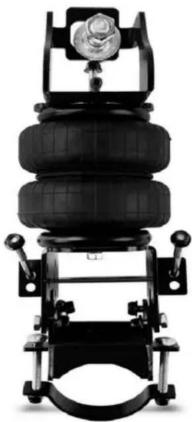
natural_image
Mechanical vehicle with black tire and mounting bracket (no visible text or symbols)POTRZEBUJE POMOCY? SKONTAKTUJ SIĘ Z NAMI!
WAŻNY!
! IMPORTANT: INSTALL ON THE LOWEST SETTING POSSIBLE FOR YOUR VEHICLE
FAILURE TO DO SO CAN RESULT IN DAMAGED BRACKETS AND CAN VOID YOUR WARRANTY


* 4 3/8 x 1/2 x 1 1/2 block supplied to use if collard is


KROK 1 - PRZYGOTUJ POJAZD
Minimum Pressure 5 psi Normal Air Pressure 60-80 psi Max Pressure 150 psi (under full load) Burst Pressure 320 psi

PODCZAS CIĘCIA LUB PRZYCINANIA PRZEWODU POWIETRZA UŻYWAJ HOS
NÓŻ, BRZYTELKA LUB OSTRY NÓŻ. CZYSTY,
KWADRATOWE CIĘCIE ZAPEWNI ZABEZPIECZENIE PRZECIEKÓW. NIE UŻYWAJ PRZECINAREK ANI
PRZEWODNIK DLA
DODAWANIE POWIETRZA
Air lines should be pushed into the push-to-connect fittings firmly, with a slight side-to-side rotational twist. Check the connection by pulling on each line to verify a robust connection.
To release the air line from the connection, first release all air from the system. Push in on the air line (step 1), push the collar in (step 2), and with the collar depressed, pull the air line out of the fitting (step 3).

natural_image
Side view line drawing of a compact camping vehicle (no text or symbols)Osiągnięcie dna

natural_image
Front view line drawing of a pickup truck (no text or symbols)Niewypoziomowany

natural_image
Front view line drawing of a classic off-road vehicle (no text or symbols)Poziom
C/O YH Consulting Limited Biuro 147,
Dom Centuriona, London Road,
Staines-upon-Thames, Surrey, TW18 4AX
| EC | REP |
E-CrossStu GmbH
Mainzer Landstr.69,
60329 Frankfurt nad Menem.
VEVOR®
TOUGH TOOLS, HALF PRICE
HULP NODIG? NEEM CONTACT MET ONS OP!
BELANGRIJK!
! IMPORTANT: INSTALL ON THE LOWEST SETTING POSSIBLE FOR YOUR VEHICLE
FAILURE TO DO SO CAN RESULT IN DAMAGED BRACKETS AND CAN VOID YOUR WARRANTY


* 4 3/8 x 1/2 x 1 1/2 block supplied to use if collard is


STAP 1- BEREID HET VOERTUIG VOOR

Minimum Pressure 5 psi Normal Air Pressure 60-80 psi Max Pressure 150 psi (under full load) Burst Pressure 320 psi

RICHTLIJNEN VOOR
LUCHT TOEVOEGEN
Air lines should be pushed into the push-to-connect fittings firmly, with a slight side-to-side rotational twist. Check the connection by pulling on each line to verify a robust connection.
To release the air line from the connection, first release all air from the system. Push in on the air line (step 1), push the collar in (step 2), and with the collar depressed, pull the air line out of the fitting (step 3).

natural_image
Side view line drawing of a compact camping vehicle (no text or symbols)natural_image
Side-view line drawings of two pickup trucks (no text or symbols)Ongelijk Niveau
C/O YH Consulting Limited Kantoor 147,
Centurion House, Londen Road,
Staines-upon-Thames, Surrey, TW18 4AX
| EC | REP |
E-CrossStu GmbH
Mainzer Landstr.69,
60329 Frankfurt am Main.
VEVOR®
TOUGH TOOLS, HALF PRICE
Technische ondersteuning en e-garantiecertificaat www.vevor.com/support
VEVOR®
TOUGH TOOLS, HALF PRICE
natural_image
Two black automotive tire suspension systems with mounting brackets and a central tire assembly (no text or symbols visible)BEHÖVS HJÄLP? KONTAKTA OSS!
VIKTIG!
! IMPORTANT: INSTALL ON THE LOWEST SETTING POSSIBLE FOR YOUR VEHICLE
FAILURE TO DO SO CAN RESULT IN DAMAGED BRACKETS AND CAN VOID YOUR WARRANTY

* 4 3/8 x 1/2 x 1 1/2 block supplied to use if collard is

STEG 1- FÖRBEREDA FORDONET


Minimum Pressure 5 psi Normal Air Pressure 60-80 psi Max Pressure 150 psi (under full load) Burst Pressure 320 psi

PUSH-TO-CONNECT (PTC) FITTINGS
Air lines should be pushed into the push-to-connect fittings firmly, with a slight side-to-side rotational twist. Check the connection by pulling on each line to verify a robust connection.
To release the air line from the connection, first release all air from the system. Push in on the air line (step 1), push the collar in (step 2), and with the collar depressed, pull the air line out of the fitting (step 3).
RIKTLINJE FÖR LÄGG TILL LUFT
natural_image
Side view illustration of a vintage-style camper van with a flat roof and two windows (no text or symbols)Bottnar
natural_image
Front view line drawing of a pickup truck (no text or symbols)
natural_image
Front view line drawing of a classic pickup truck (no text or symbols)NivåOjämn
C/O YH Consulting Limited Office 147,
Centurion House, London Road,
Staines-upon-Thames, Surrey, TW18 4AX
| EC | REP |
E-CrossStu GmbH
Mainzer Landstr.69,
60329 Frankfurt am Main.
VEVOR®
TOUGH TOOLS, HALF PRICE
www.vevor.com/support


