704-48205-P1 - Remote control Vevor - Free user manual and instructions
Find the device manual for free 704-48205-P1 Vevor in PDF.

| Product Type | Remote control box for outboard motor |
| Brand | Vevor |
| Model | 704-48205-P1 |
| Dimensions (approx.) | 200 x 150 x 100 mm |
| Weight (approx.) | 1.5 kg |
| Power Supply | Mechanical (control cables); 12 V DC for trim/tilt (if equipped) |
| Number of Compatible Engines | Single or dual (depending on version) |
| Main Functions | Throttle control, gear shifting (forward, neutral, reverse), electric trim and tilt (if equipped), free accelerator |
| Throttle Control Type | Push-to-open or pull-to-open (configurable) |
| Lever Travel Angle | 35° for gear, 67° to 100° for throttle |
| Safety | Start-in-gear protection device (neutral required) |
| Friction Adjustment | Throttle friction screw at the back of the box |
| Housing Material | Reinforced plastic |
| Cable Bend Radius | Greater than 200 mm (7.87 in) |
| Maintenance and Cleaning | Apply water-resistant grease (Yamaha Grease A) to moving surfaces; clean with a soft cloth |
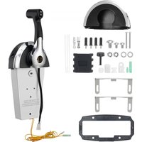
| Spare Parts Included | Circlips, cable seals, grommets, washers, nuts, screws, packaging, manual, copper nut, plastic mounting blocks |
| Repairability | Spare parts available from the manufacturer; throttle type conversion procedure described in the manual |
| General Information | Compliant with EU Directive 2012/19/EU (WEEE); technical support and warranty at www.vevor.com/support; imported by various entities depending on region |
Frequently Asked Questions - 704-48205-P1 Vevor
User questions about 704-48205-P1 Vevor
0 question about this device. Answer the ones you know or ask your own.
Ask a new question about this device
Download the instructions for your Remote control in PDF format for free! Find your manual 704-48205-P1 - Vevor and take your electronic device back in hand. On this page are published all the documents necessary for the use of your device. 704-48205-P1 by Vevor.
USER MANUAL 704-48205-P1 Vevor
Technical Support and E-Warranty Certificate www.vevor.com/support
OUTBOARD REMOTE CONTROLBOX
MODEL:704-48205-P1
We continue to be committed to provide you tools with competitive price. "Save Half", "Half Price" or any other similar expressions used by us only represents an estimate of savings you might benefit from buying certain tools with us compared to the major top brands and does not necessarily mean to cover all categories of tools offered by us. You are kindly reminded to verify carefully when you are placing an order with us if you are actually saving half in comparison with the top major brands.
VEVOR®
TOUGH TOOLS, HALF PRICE
OUTBOARDREMOTE
CONTROLBOX
natural_image
Technical line drawing of a mechanical device with lever and base (no text or symbols)N EED HEL P? C O N T A C T U S !
Have product questions? Need technical support? Please feel free to contact us:
Technical Support and E-W arranty Certification
www.vevo r.com /support
This is the original instruction, please read all manual instructions carefully before operating. VEVOR reserves a clear interpretation of o user manual. The appearance of the product shall be subject to the product you received. Please forgive us that we won't inform you ag there are any technology or software updates on our product.

NOTICE
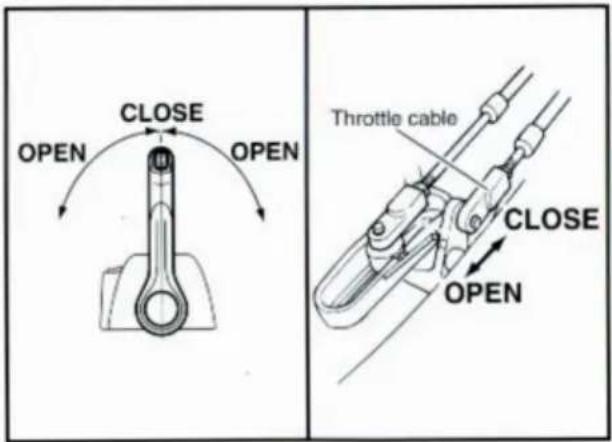
This remote control box is so designed that both shift and throttle can be actuated by operating a remote control lever. For a correct operation and installation of the remote control box, please read this manual carefully and thoroughly. Explanations will be made based on a push-to-open throttle type equipped with the power trim and tilt switch.
Particularly important information is distinguished in this manual by the following notations.

The Safety Alert Symbol means ATTENTION! BECOME ALERT! YOUR SAFETY IS INVOLVED!
AWARNING
Failure to follow WARNING instructions could result in severe injury or death to the machine operator, a bystander, or a person inspecting or repairing the remote control box.
The twin remote control box are used as a base for the explanations and illustrations in this manual. Therefore, some items may not apply to every model.
CAUTION:
A CAUTION indicates special precautions that must be taken to avoid damage to the remote control box.
NOTE:
A NOTE provides key information to make procedures easier or clearer.
Specifications given in this manual may be subject to change without notice.

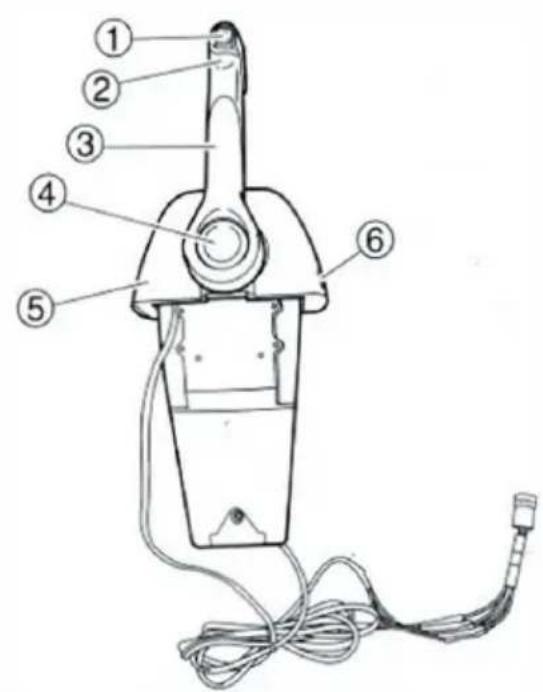
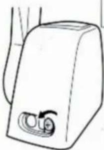
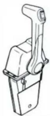
MAIN COMPONENTS OF SINGLE ENGINE TYPE
Remote control box for single engine
STANDARD
natural_image
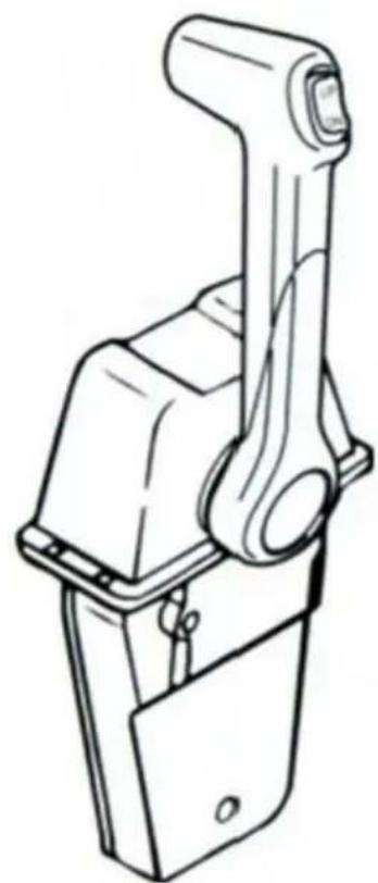
Technical line drawing of a mechanical lever assembly (no text or symbols)① Power trim and tilt switch
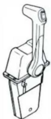
② Grip
③ Control lever
④ Free accelerator button
⑤ Cover
⑥ Throttle friction adjuster
NOTE:
Depending on the specification, some models are not equipped with the power trim and tilt switch.
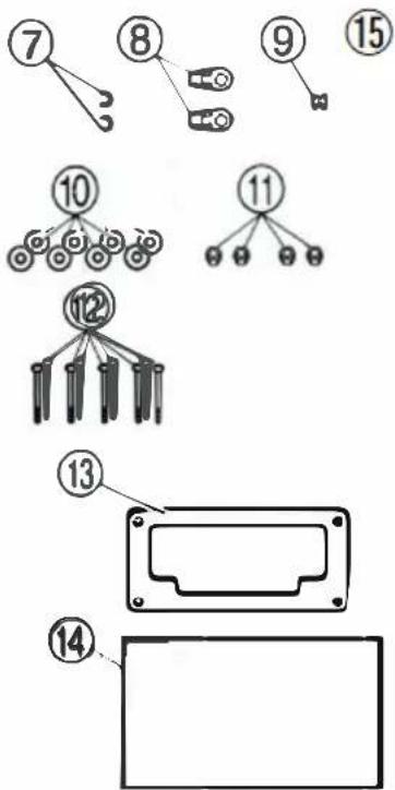
Part list
| No | Components | Picture | Qty |
| 7 | Circlip | 2 | |
| 8 | Cable Joint |  | 2 |
| 9 | Grommet |  | 1 |
| 10 | Washer(6) | 4 | |
| 11 | Nut(M5) | 4 | |
| 12 | Screw(M5*30) |  | 5 |
| 13 | Packing |  | 1 |
| 14 | Manual | 1 | |
| 15 | Copper Nut(M5) | 1 | |
| 16 | Plastic mounting block 1 | 1 | |
| 17 | Plastic mounting block 2 | 1 |
NOTE:
Depending on the specification, some models are not equipped with the power trim and tilt switch.
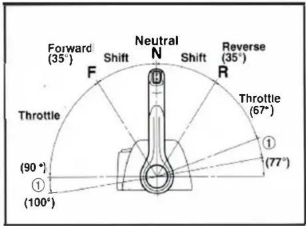
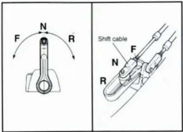
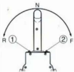
Forward and reverse
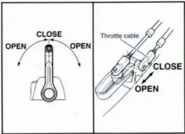
To shift into forward and reverse, rotate the control lever downward about 35 (detent position) to the F side and R side, respectively. When the control lever is further rotated downward, the throttle opens.
① Throttle adjustable range
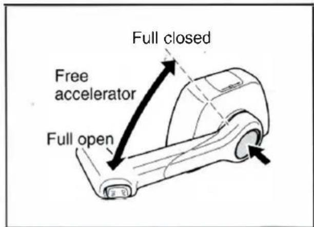
Free accelerator
Set the control lever to neutral (N) and while pushing the free accelerator button, rotate the control lever. The throttle can be opened without shifting into any gear.
NOTE:
The control lever must be rotated more than 35° from neutral; otherwise, the throttle cannot be opened.
CAUTION:
- It is impossible to operate the free accelerator button unless the control lever is in neutral.
- After operating the free accelerator button, set the control lever to neutral (N), and the free accelerator button will move automatically to its set position so that it can be freely turnend to forward and reverse.
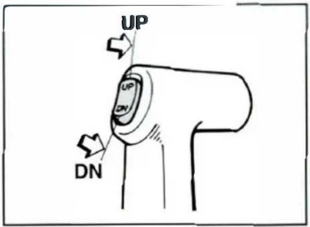
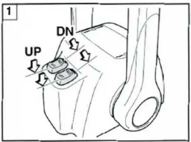
Power trim and tilt switch
The power trim and tilt switch is attached to the control lever grip and twin cover. Pushing it UP trims up and tilts up the engine, and pushing it DOWN trims down and tilts down the engine.
NOTE:
- When operating the remote control boxes for twin engines, the power trim and tilt switch on the control lever grip is interlocked with both engines.
- While the switch button is being pressed, the trim/tilt motor turns and adjusts the engine mounting angle. When the switch button is released, the engine will stop in its position.
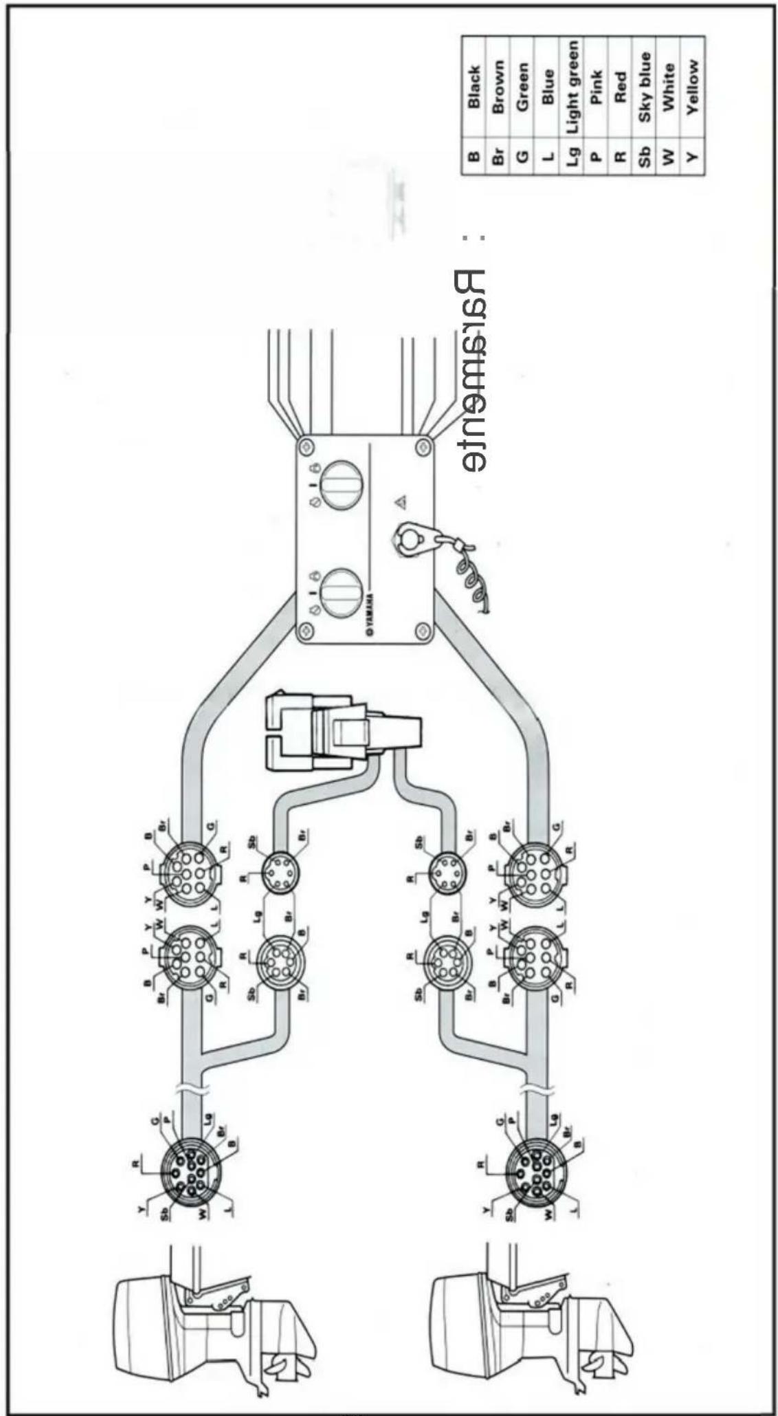
1 Remote control box for twin-engine
Start-in-gear protection device
WARNING
This control will provide startin gearprotection meeting U.S.C.G requirements of CFR 183, SUBPARTL.
WARNING
Ensure shift controls in neutral before starting motor.
This feature permits the engine to be started only when it is in neutral. Always select neutral before starting the engine.
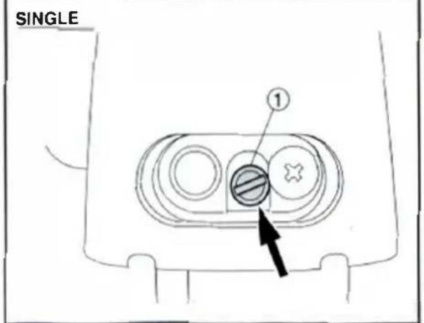
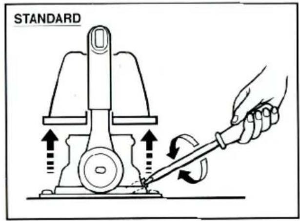
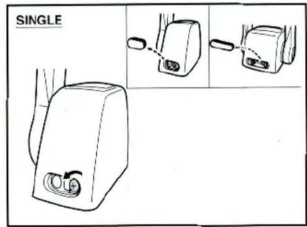
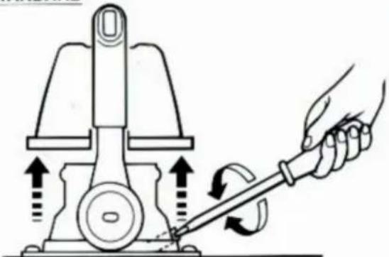
Controllever friction adjustment
On this remote control box, control lever friction is adjustable in the following manner:
- By turning in or out the throttle friction screw at the rear of the remote control box, the stiffness of the controlever can be adjusted. Turning the adjusting screw to the right makes the control lever stiff to turn, and turning it to the left makes the lever easier to turn.
① Adjusting screw
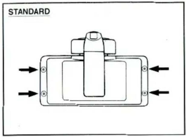
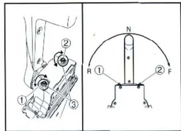
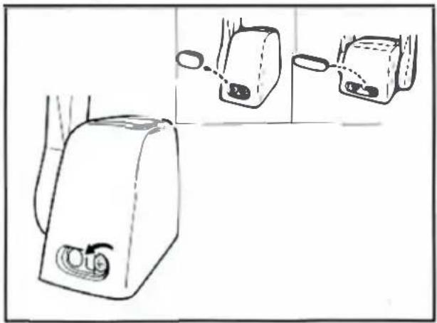
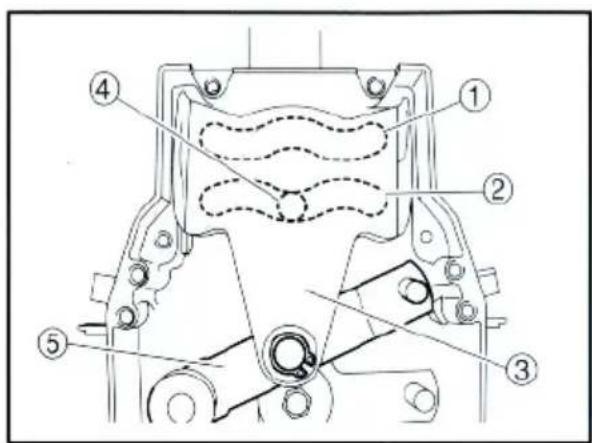
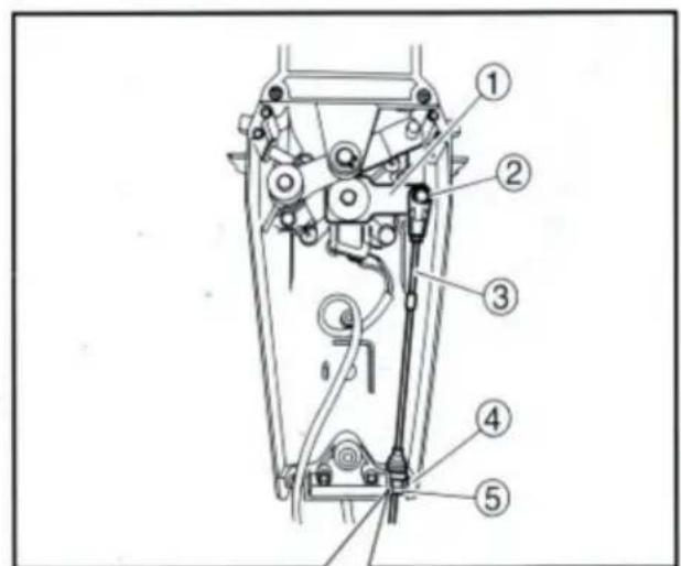
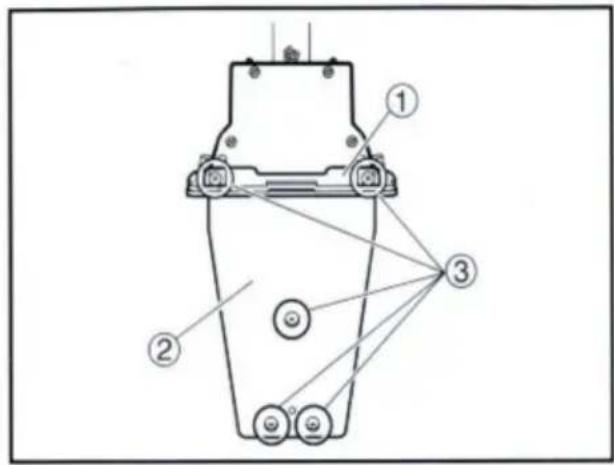
Throttle opening adjustment
The remote control box is capable of adjusting the throttle opening in the following manner:
-
Loosen the screws securing the cover and remove it from the body.
-
Loosen the locknut, and adjust the throttle opening by turning the stopper bolt. Turning the bolt clockwise decreases the throttle opening.
Turning the bolt counterclockwise increases the throttle opening.
① Stopper bolt on the reverse side
② Stopper bolt on the forward side
③ Lock nut
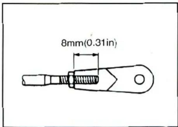
CAUTION:
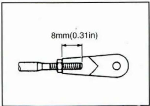
Do not allow the stopper bolt to project 8 mm (0.3 in) or more from the nut surface. Otherwise, the stopper contacts the cover.
- After adjusting, tighten the locknut.
TIGHTENING TORQUE:
5-8 Nm (50-80 kgf·cm, 3.6-5.8 ft·lb)
- Secure the cover to the body with the screws.
WARNING
Incorrect selection or installation of a remote control may result in sudden and unexpected loss of control, thus resulting in a serious accident. Please consult your Yamaha dealer.
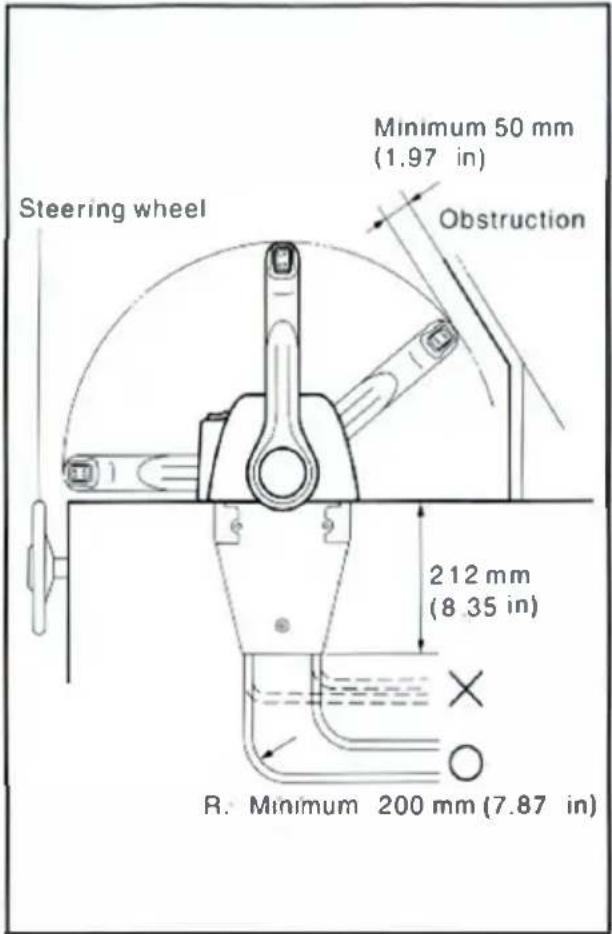
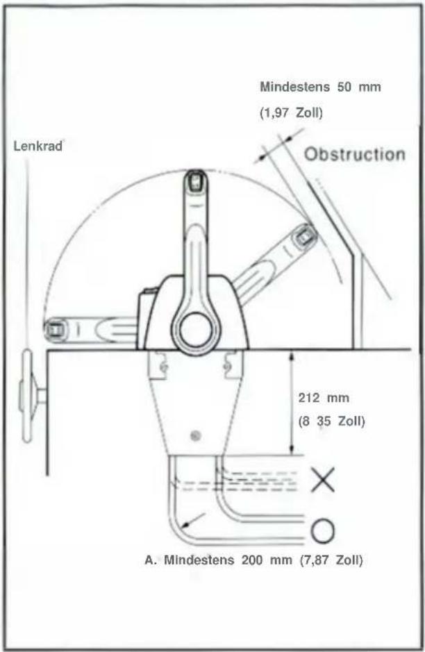
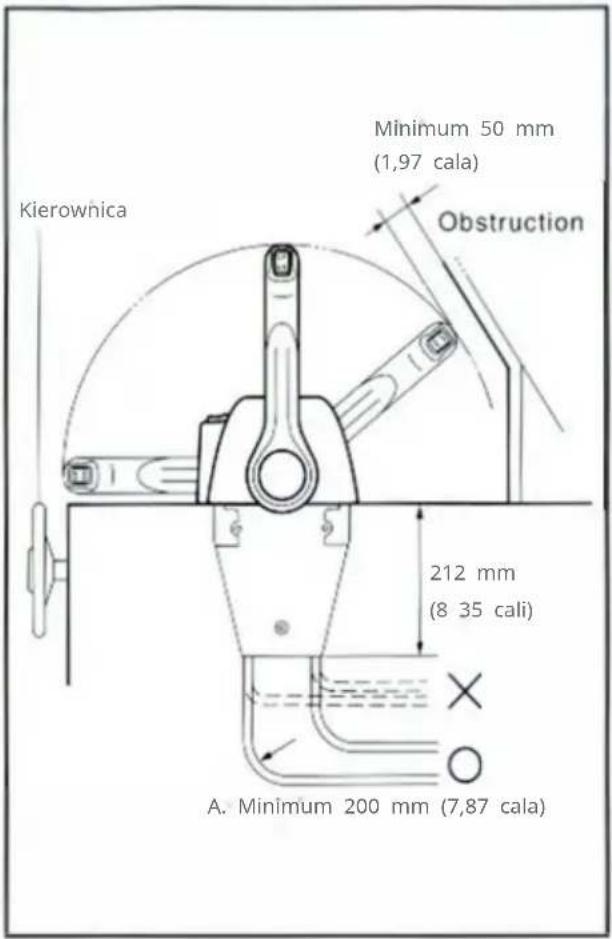
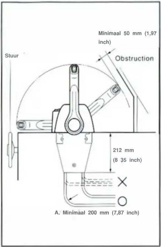
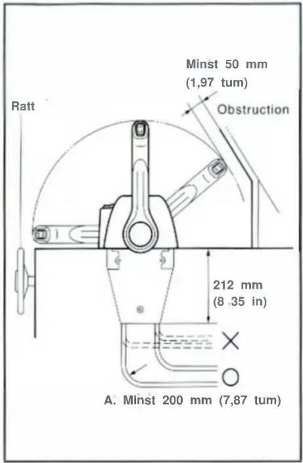
Remote control box position
Select the proper position for the remote control box, and stick the template on the selected position, then drill hole through it. When selecting the control box position, keep the following in mind:
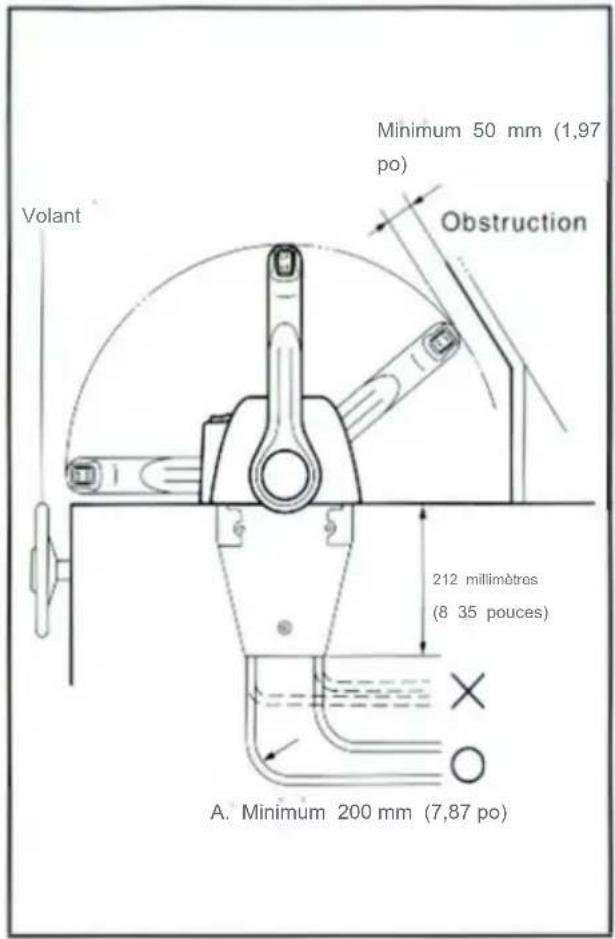
- The remote control box should be set in a position in which it does not obstruct the operations of the control lever and switches. Make sure there is no obstruction on the path of the remote control cables.
- AI bw a space so that the bottom of the remote control box does not contact any other parts.
- Provide a space so that the remote control cables can be routed without bending sharply. The radius of a cable bend should be more than 200 mm (7.87 in).
CAUTION:
Sharp bends (less than 200 mm (7.87 in) in radius) of the cables will obstruct a smooth movement of the cables and shorten cable life.
natural_image
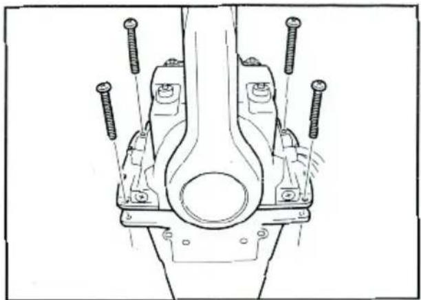
Line drawing of a device with two views showing internal components (no text or symbols)Installing the remote control cables
CAUTION:
Cable connection should be started first from the remote control box side. If started from the engine side, cable adjustment will be impossible in some cases.
NOTE:
Use the genuine YAMAHA cables.
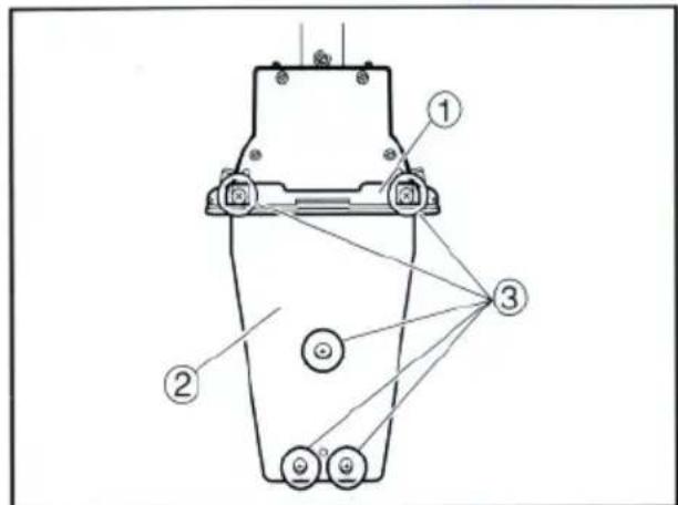
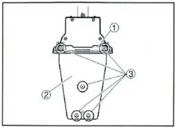
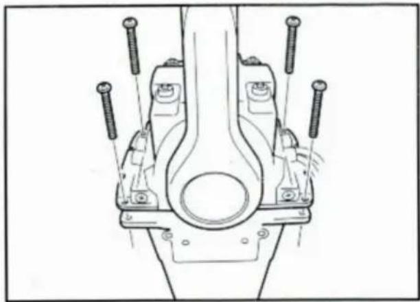
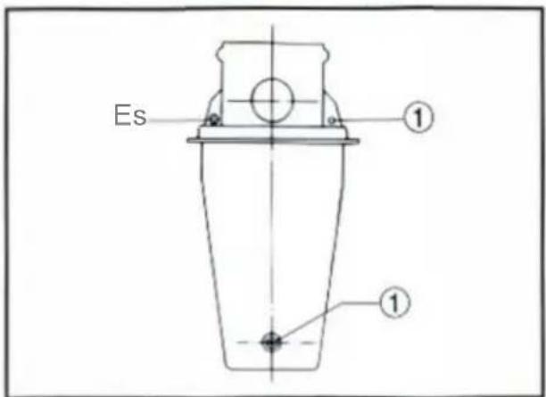
- Loosen the screws securing the cover and remove it from the body.
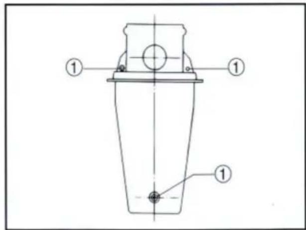
- Loosen the three screws securing the two remote control boxes and put the remote control boxes apart.
① Screw
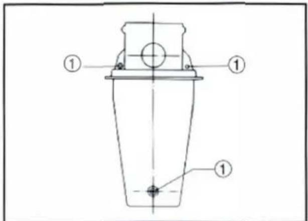
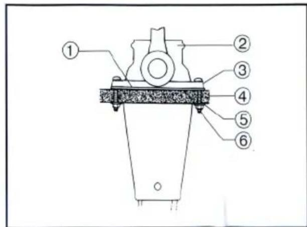
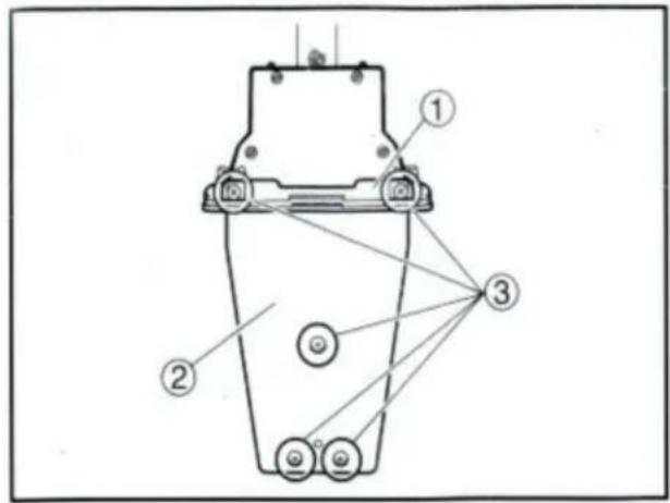
- Loosen the five screws and remove the mounting flange, packing, and back plate.
NOTE:
The mounting flange on the back plate side should be removed.
① Mounting flange
② Back plate
③ Screws

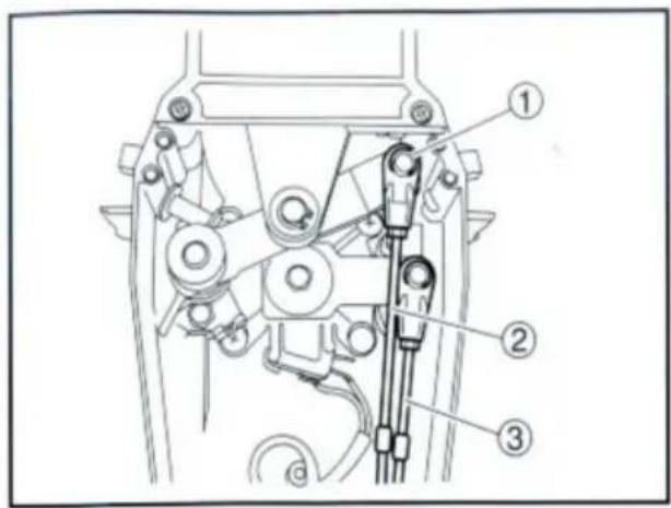
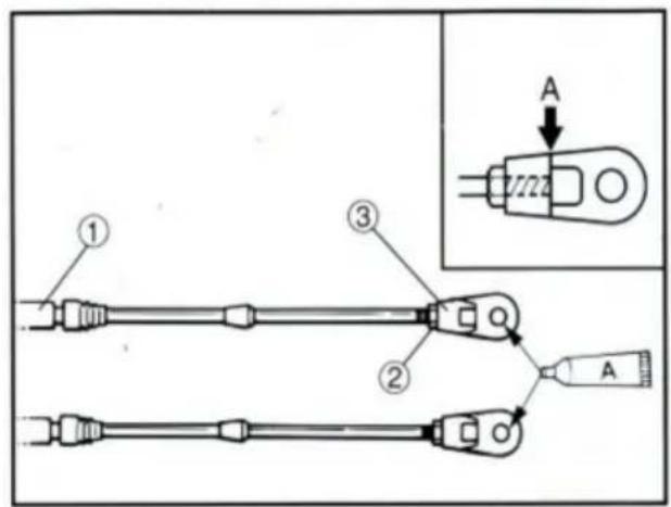
- Screw the cable joint on to the remote control cable up to point "A" (11mm), and tighten the lock nuts. Before installing the cable joints, apply the water-resistant grease (Yamaha Grease A) to the threaded holes in the cable joints.
① Remote control cable
② Lock nut
③ Cable joint
TIGHTENING TORQUE:
1.5–1.8 Nm (15–18 kgf·cm, 1.1–1.3 ft·lb)
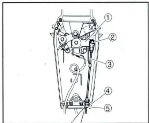
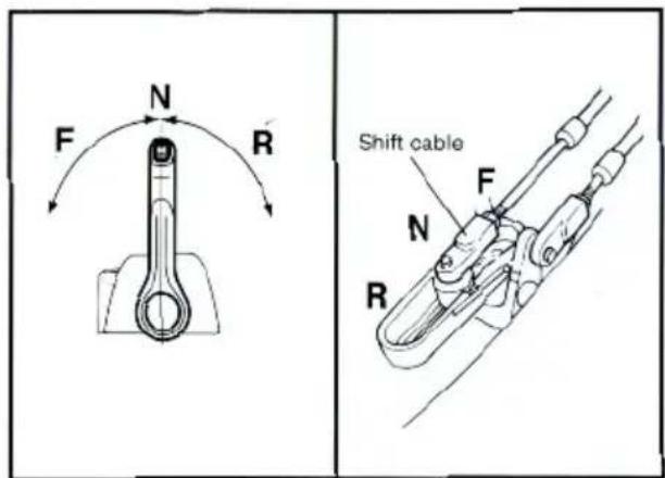
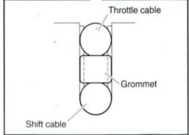
- Insert the shift cable into the housing clamp so that the groove on its end fits over the ridge in the clamp. Fit the cable joint over the pin on the end of the shift arm, and lock it with the circlip.
① Shift arm
② Circlip
③ Shift cable
④ Clamp groove
⑤ Grommet
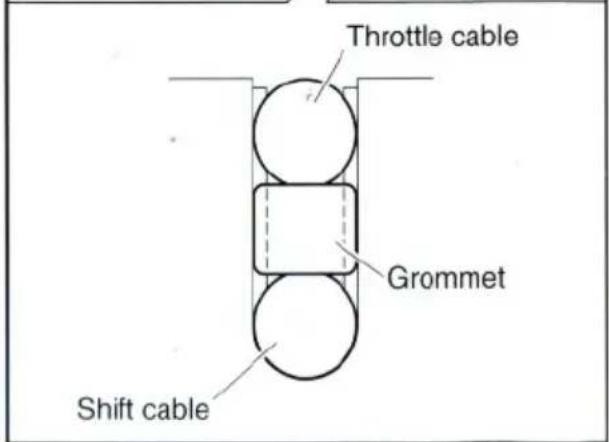
- Fit the grommet in the clamp groove.

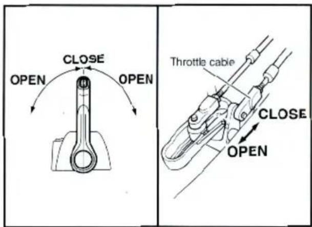
- Connect the throttle cable to the throttle arm in the same manner.
① Circlip
② Throttle cable
③ Shift cable
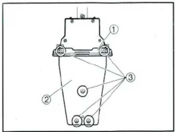
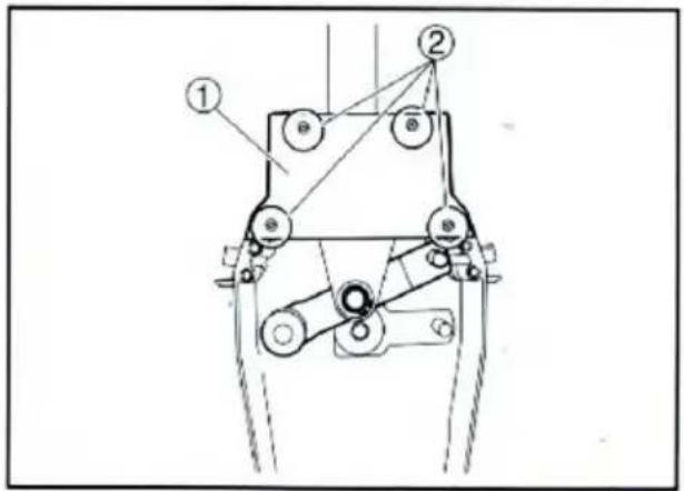
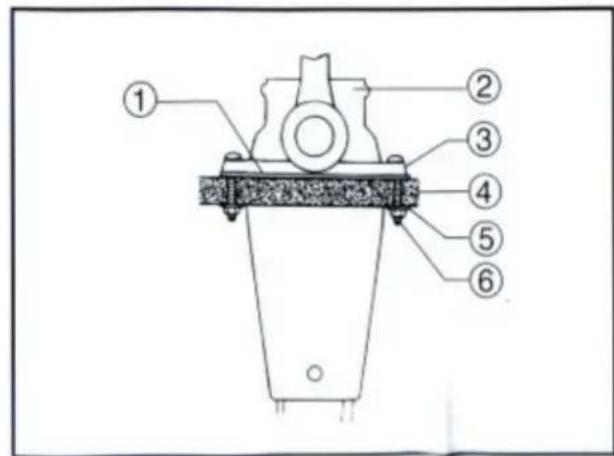
- Hold the back plate and mounting flange firmly with the five screws, and fit the packing in place.
① Mounting flange
② Back plate
③ Screws
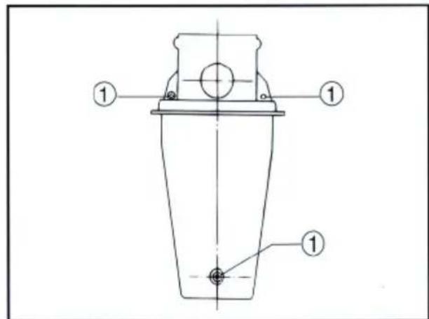
- Secure the two remote control boxes with the three screws.
① Screw
- After installing the remote control cables, temporarily secure the remote control boxes to the predetermined position with the screws and nuts.
① Packing
② Remote control box
③ Screw
④ Hull
⑤ Washer
⑥ Nut
natural_image
Technical line drawing of a mechanical assembly with screws and mounting brackets (no text or symbols)- Peel the paper off the back of packing, and adhere the packing to the boat hull so that the holes in the packing align with the remote control box mounting screw holes in the hull.
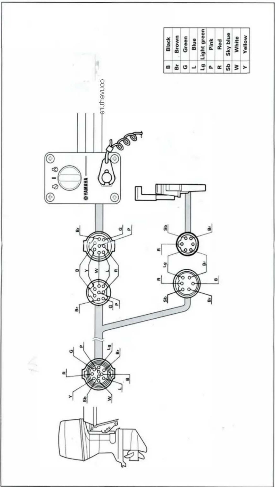
CONNECTING THE REMOTE CONTROL CABLE TO THE ENGINE
Checkpoints of cable joint
Shift:
Operate the control lever a few times and check to see that the shift lever on the engine side moves correctly.
Throttle:
Operate the control lever a few times and make sure that when it is returned to the neutral position the throttle lever on the engine side is set to the full-closed position.
Free accelerator:
Push the free accelerator button, and turn the control lever downward until it stops, then make sure that when it is returned to the neutral position, the free accelerator button is automatically reset
Adjustment of cable joint
Adjust the cable joints on the engine side when the above checkpoints do not operate correctly.
CAUTION:
The cable joints on the engine side must be screwed onto the remote control cables at least 8 mm (0.3 in).
Adjust the cable joint on the remote control side if the adjustment cannot be made only on the engine side.
-
After connecting the cables to the engine, move the control lever from lock to lock several times and check for good operation of the engine and remote control box.
-
Firmly secure the remote control box (which is temporarily held with the screws) to the hull.
CAUTION:
Check that the cables are not sharply bent (less than 200 mm (7.87 in) in radius) or unnecessarily bent. (The number of bends should be minimized.) Also, check that no portions of the cables are clamped so hard as to deform the cable outers.
- Secure the cover to the body with the screws.

CHANGE FROM THE PUSH-TO-OPEN THROTTLE TYPE TO THE PULL-TO-OPEN THROTTLE TYPE
The remote control box permits the change from the push-to-open throttle type to the pull-to-open type by changing some of the parts positions.
This manual discusses the procedure for changing from the push-to-open throttle type to the pull-to-open type.
Therefore, if it has to be changed from the pull-to-open type to the push-to-open type, simply reverse the procedure.
CAUTION:
When reinstalling parts, apply the water-resistant grease (Yamaha Grease A) to moving paths and contact surfaces of parts.
- Remove the cover from the body.
- Loosen the five screws and remove the mounting flange, packing and back plate.
① Mounting flange
② Back plate
③ Screws
- Remove the four screws and remove the dwell plate retainer.
① Dwell plate retainer
② Screws
- Remove the circlips and remove the dwell plate. Position the throttle arm assembly so that it turns downward.
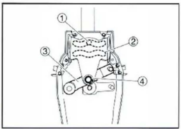
① Roller
② Dwell plate
③ Throttle arm assembly
④ Circlip
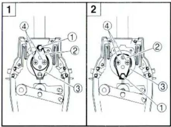
- Remove the two screws and remove the throttle lever assembly. Position the throttle lever assembly so that it faces downward and secure it with the two screws.
TIGHTENING TORQUE: 5–8 Nm (50–80 kgf·cm, 3.6–5.8 ft·lb)
1 Push-to-open throttle type
2 Pull-to-open throttle type
① Roller
② Throttle lever assembly
③ Stopper
④ Screws
- Align both the cam groove (for pull-to-open) in the dwell plate and the roller in the throttle lever assembly with the specific position, and lock the throttle arm assembly and dwell plate with the circlip.
NOTE: ____ Make sure the circlip are correctly fitted in place.
① Groove for push-to-open
② Groove for pull-to-open
③ Dwell plate
④ Roller
⑤ Throttle arm assembly
- Secure the dwell plate retainer with the four screws.
- Install the mounting flange, back plate with the five screws.
NOTE: When installing the back plate, use care so that the wire harness is not pinched.
- Install the cover on the body.

VERIFYING CORRECT OPERATION
Be sure to verify that the remote control box operates correctly after installation.
- Follow the procedure for starting the engine and verify that the engine starts properly.
- Pull the lanyard to remove the lock plate from the engine stop lanyard switch and verify that the engine stops.
NOTE: If the remote control box fails to operate correctly, verify that the installation procedure was followed properly.
To ensure a longer life of the remote control box, be sure to take the following steps when storing it for a long period of time.
- Remove the cable joints and apply water-resistant grease (Yamaha grease A) to the thread portion of the inner cable.
- Also apply water-resistant grease (Yamaha grease A) to inner parts of the remote control box, particularly to contact surfaces of moving parts. If any rust is found, remove it and apply the grease.
- Avoid bending the cables into a loop as much as possible. But if they have to be looped, the loop diameter should be more than one meter (40 in).
- Select a dry place for storage.

SWITCH PANEL MOUNTING

WARNING
When installing or removing electrical parts, be sure to disconnect the battery wires from the battery terminals. When connecting the battery wires to the battery terminals, be sure to turn off the main switch and remove the switch key. Otherwise you may receive an electric shock, or sparks may ignite the fuel causing an explosion.
CAUTION:
Install the switch panel onto the dashboard. Select a location allowing easy access from the helmsman's seat. If the boat has no dashboard, the switch panel should be installed in a location protected from water spray.
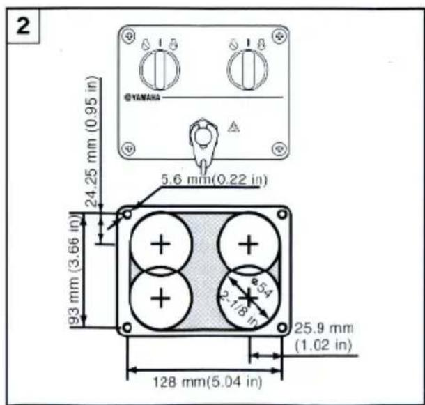
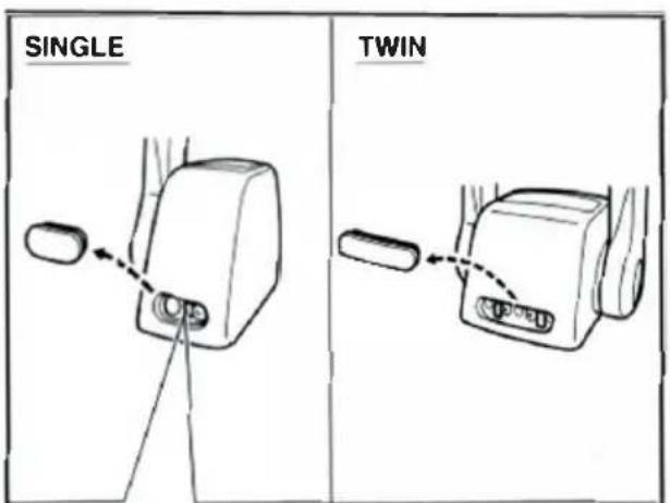
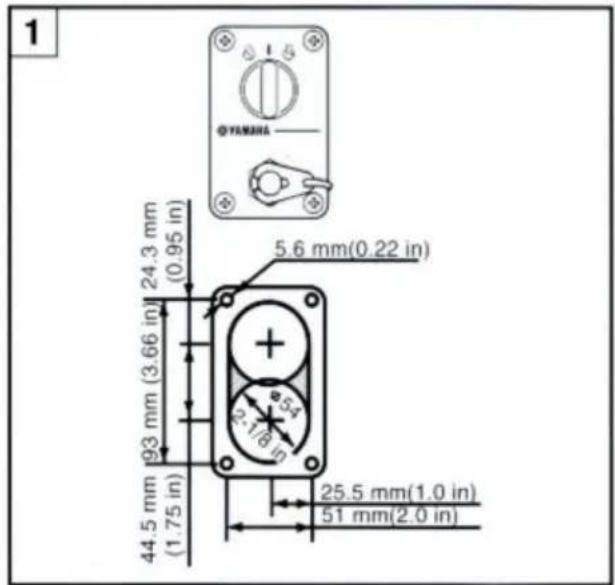
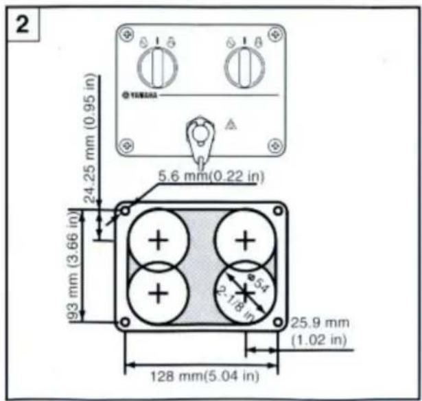
1 Switch panel for single engine
2 Switch panel for twin engine
- Cut a hole in the instrument panel as indicated in this mounting diagram. Using a 2-1/16-inch hole saw, make holes and then cut out the center portion as shown.
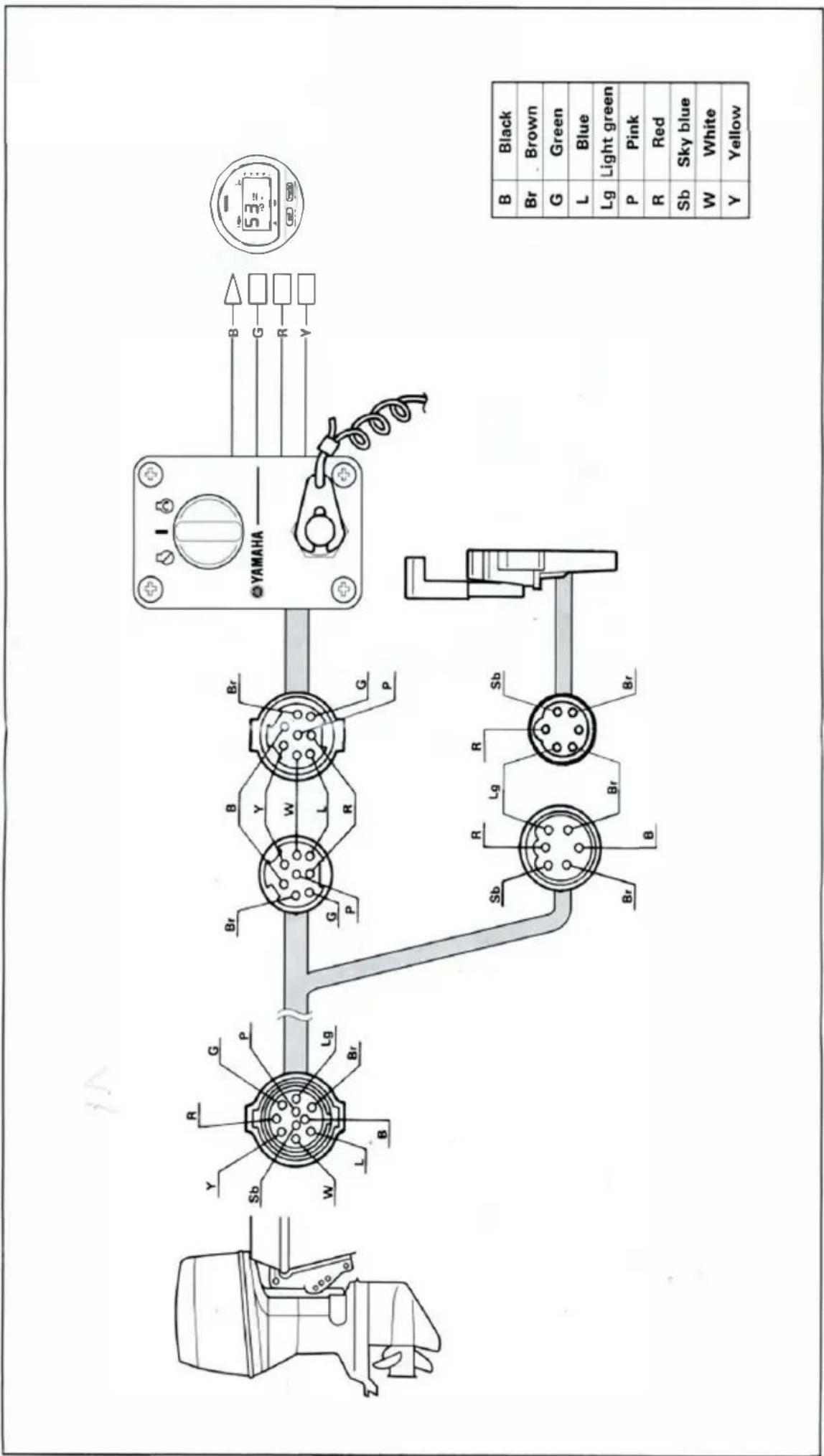
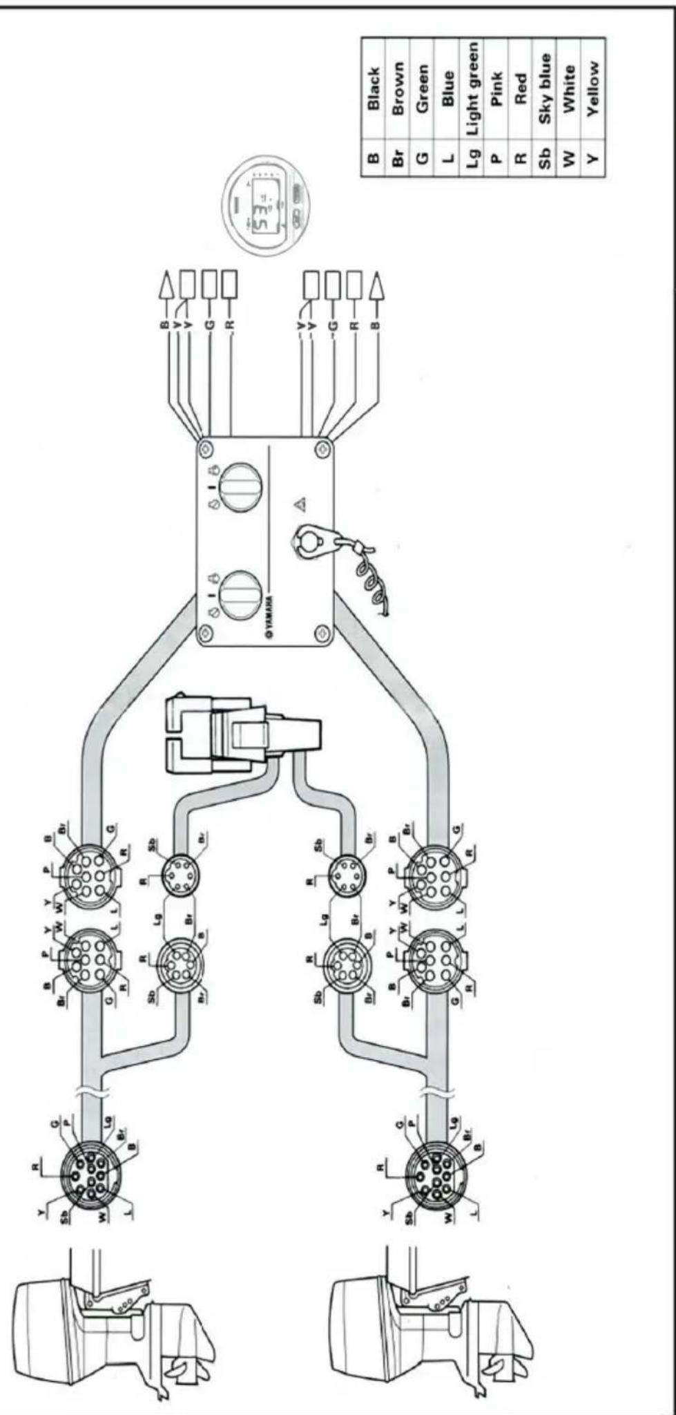
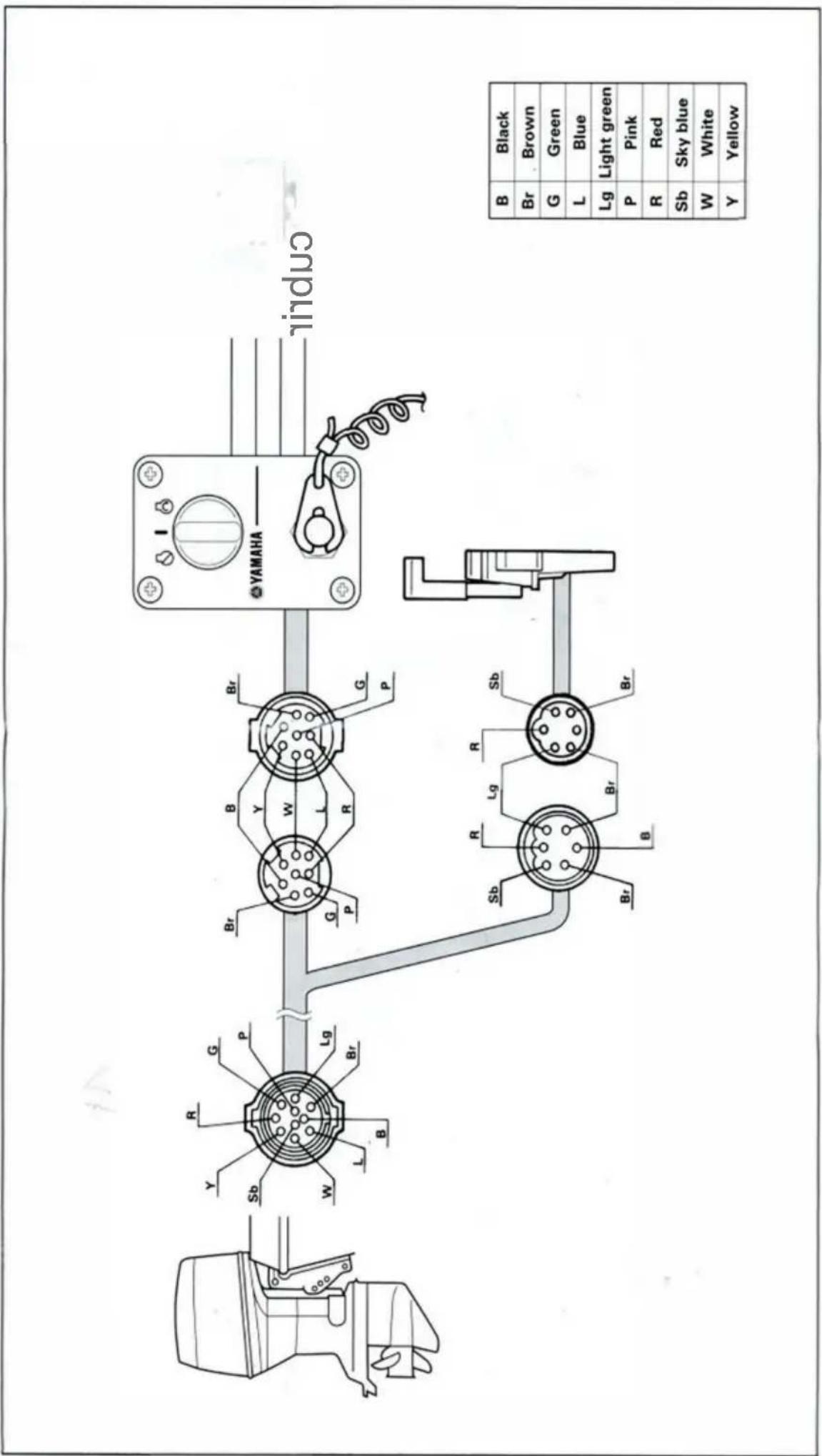
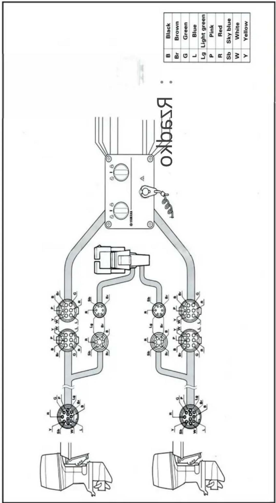
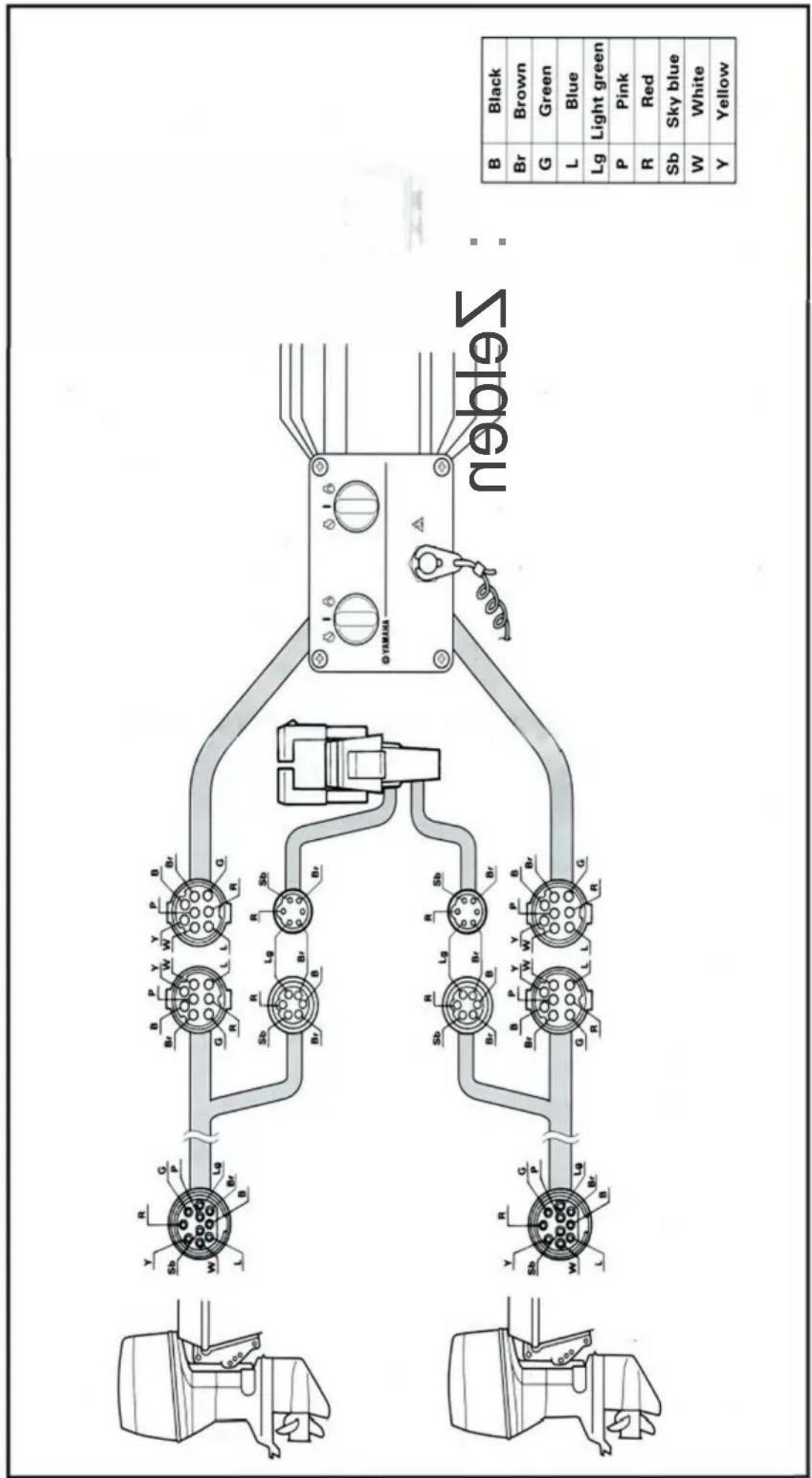
- Connect the wire harness to the switch panel assembly, and pass it back through the hole.
- Secure the switch panel assembly to the instrument panel with the bind screws, washers and nuts.
Twin engine
without choke switch

natural_image
Symbol of a trash bin with crossed lines and a blank rectangular base (no text or numbers)CORRECT DISPOSAL
This product is subject to the provision of european Directive2012/19/EU. The symbol showing a wheeliebin crossed through indicates that the product requires separaterefuse collection in the EuropeanUnion. This applies to the product and all accessories marked with this symbol. Productsmarked as such may not be discarded with normal domestic waste, but must be taken to acollectionpoint for recycling electrical and electronic devices.
Address: Baoshanqu Shuangchenglu 803long 11hao 1602A-1609shi Shanghai Imported to AUS: SIHAO PTY LTD.1 ROKEVA STREETEASTWOOD NSW 2122
Australia Imported to USA: Sanven Technology Ltd. Suite 250, 9166 Anaheim Place, Rancho Cucamonga, CA 91730
EC REP : SHUNSHUN GmbH.
Römeräcker 9 Z2021,76351 Linkenheim-Hochstetten, Germany
Tel: +49 1727041930 euvertreter@gmail.com
UK REP : Pooledas Group Ltd
Unit 5 Albert Edward House, The Pavilions Preston, United Kingdom
Tel: 01772418127 pooledas123@gmail.com
VEVOR®
TOUGH TOOLS, HALF PRICE
Technical Support and E-Warranty Certificate
www.vevo r.com /sup port
VEVOR®
TOUGH TOOLS, HALF PRICE
OU AUSSI OARDREMO TE
BOÎTIER DE COMMANDE
MODÈLE : 704-48205-P1
natural_image
Line drawing of a mechanical lever mechanism (no text or symbols)BESOIN D'AIDE ? AVEC TAC TUS !


Kunji]
STANDARD

natural_image
Technical line drawing of a mechanical device with lever and base (no text or symbols)natural_image
Pure mechanical component diagram without any text, numbers, or symbolsSTANDARD

natural_image
Illustration of a hand using a tool to press or install a mechanical component, with arrows indicating motion (no text or symbols present)SINGLE

natural_image
Simple line drawing of a device with a button and scroll (no text or symbols)
natural_image
Diagram showing two hand positions of a device with a handle, no text or symbols present

Throttle opening adjustment
The remote control box is capable of adjusting the throttle opening in the following manner:
- Loosen the screws securing the cover and remove it from the body.
- Loosen the locknut, and adjust the throttle opening by turning the stopper bolt. Turning the bolt clockwise decreases the throttle opening.
Turning the bolt counterclockwise increases the throttle opening.
① Stopper bolt on the reverse side
② Stopper bolt on the forward side
③ Lock nut
CAUTION:
Do not allow the stopper bolt to project 8 mm (0.3 in) or more from the nut surface. Otherwise, the stopper contacts the cover.
- After adjusting, tighten the locknut.
TIGHTENING TORQUE:
5–8 Nm (50–80 kgf·cm, 3.6–5.8 ft·lb)
Secure the cover to the body with the screws.
INSTALLATION DU BOÎTIER DE TÉLÉCOMMANDE
- Loosen the five screws and remove the mounting flange, packing, and back plate.
NOTE:
The mounting flange on the back plate side should be removed.
① Mounting flange
② Back plate
③ Screws

- Screw the cable joint on to the remote control cable up to point "A" (11mm), and tighten the lock nuts. Before installing the cable joints, apply the water-resistant grease (Yamaha Grease A) to the threaded holes in the cable joints.
① Remote control cable
② Lock nut
③ Cable joint
TIGHTENING TORQUE:
1.5–1.8 Nm (15–18 kgf·cm, 1.1–1.3 ft·lb)

- Insert the shift cable into the housing clamp so that the groove on its end fits over the ridge in the clamp. Fit the cable joint over the pin on the end of the shift arm, and lock it with the circlip.
① Shift arm
② Circlip
③ Shift cable
④ Clamp groove
⑤ Grommet
- Fit the grommet in the clamp groove.

- Connect the throttle cable to the throttle arm in the same manner.
① Circlip
② Throttle cable
③ Shift cable

- Hold the back plate and mounting flange firmly with the five screws, and fit the packing in place.
① Mounting flange
② Back plate
③ Screws

- Secure the two remote control boxes with the three screws.
① Screw

- After installing the remote control cables, temporarily secure the remote control boxes to the predetermined position with the screws and nuts.
① Packing
② Remote control box
③ Screw
④ Hull
⑤ Washer
⑥ Nut

INSTALLING THE REMOTE CONTROL BOX

natural_image
Technical line drawing of a mechanical component with screws and mounting holes (no text or symbols)- Peel the paper off the back of packing, and adhere the packing to the boat hull so that the holes in the packing align with the remote control box mounting screw holes in the hull.

CONNECTING THE REMOTE CONTROL CABLE TO THE ENGINE
Checkpoints of cable joint
Shift:
Operate the control lever a few times and check to see that the shift lever on the engine side moves correctly.
Throttle:
Operate the control lever a few times and make sure that when it is returned to the neutral position the throttle lever on the engine side is set to the full-closed position.
Free accelerator:
Push the free accelerator button, and turn the control lever downward until it stops, then make sure that when it is returned to the neutral position, the free accelerator button is automatically reset.
Adjustment of cable joint
Adjust the cable joints on the engine side when the above checkpoints do not operate correctly.
CAUTION:
The cable joints on the engine side must be screwed onto the remote control cables at least 8 mm (0.3 in).
Adjust the cable joint on the remote control side if the adjustment cannot be made only on the engine side.

- After connecting the cables to the engine, move the control lever from lock to lock several times and check for good operation of the engine and remote control box.
- Firmly secure the remote control box (which is temporarily held with the screws) to the hull.
CAUTION:
Check that the cables are not sharply bent (less than 200 mm (7.87 in) in radius) or unnecessarily bent. (The number of bends should be minimized.) Also, check that no portions of the cables are clamped so hard as to deform the cable outers.
- Secure the cover to the body with the screws.

CHANGEMENT DE LA MANETTE DES GAZ POUSSER POUR OUVRIR TYPE AU TYPE D'ACCÉLÉRATEUR À TIRER POUR OUVRIR
- Remove the two screws and remove the throttle lever assembly. Position the throttle lever assembly so that it faces downward and secure it with the two screws.
TIGHTENING TORQUE: 5–8 Nm (50–80 kgf·cm, 3.6–5.8 ft·lb)
1 Push-to-open throttle type
2 Pull-to-open throttle type
① Roller
② Throttle lever assembly
③ Stopper
④ Screws
- Align both the cam groove (for pull-to-open) in the dwell plate and the roller in the throttle lever assembly with the specific position, and lock the throttle arm assembly and dwell plate with the circlip.
NOTE:
Make sure the circlip are correctly fitted in place.
① Groove for push-to-open
② Groove for pull-to-open
③ Dwell plate
④ Roller
⑤ Throttle arm assembly
- Secure the dwell plate retainer with the four screws.
- Install the mounting flange, back plate with the five screws.
NOTE:
When installing the back plate, use care so that the wire harness is not pinched.
- Install the cover on the body.

VERIFYING CORRECT OPERATION
Be sure to verify that the remote control box operates correctly after installation.
- Follow the procedure for starting the engine and verify that the engine starts properly.
- Pull the lanyard to remove the lock plate from the engine stop lanyard switch and verify that the engine stops.
NOTE:
If the remote control box fails to operate correctly, verify that the installation procedure was followed properly.

NOTES ON STORAGE
To ensure a longer life of the remote control box, be sure to take the following steps when storing it for a long period of time.
- Remove the cable joints and apply water-resistant grease (Yamaha grease A) to the thread portion of the inner cable.
- Also apply water-resistant grease (Yamaha grease A) to inner parts of the remote control box, particularly to contact surfaces of moving parts. If any rust is found, remove it and apply the grease.
- Avoid bending the cables into a loop as much as possible. But if they have to be looped, the loop diameter should be more than one meter (40 in).
- Select a dry place for storage.

SWITCH PANEL MOUNTING
WARNING
When installing or removing electrical parts, be sure to disconnect the battery wires from the battery terminals. When connecting the battery wires to the battery terminals, be sure to turn off the main switch and remove the switch key. Otherwise you may receive an electric shock, or sparks may ignite the fuel causing an explosion.
CAUTION:
Install the switch panel onto the dashboard. Select a location allowing easy access from the helmsman's seat. If the boat has no dashboard, the switch panel should be installed in a location protected from water spray.
1 Switch panel for single engine
2 Switch panel for twin engine
- Cut a hole in the instrument panel as indicated in this mounting diagram. Using a 2-1/16-inch hole saw, make holes and then cut out the center portion as shown.
- Connect the wire harness to the switch panel assembly, and pass it back through the hole.
- Secure the switch panel assembly to the instrument panel with the bind screws, washers and nuts.


natural_image
Symbol of a trash bin with crossed lines indicating no waste, and a solid black rectangle below (no text or labels)ÉLIMINATION CORRECTE
natural_image
Line drawing of a mechanical lever mechanism (no text or symbols)BRAUCHEN SIE HILFE? MIT TAC TUS!
Qi 15

12 :zwei
Kunji]
STANDARD

natural_image
Technical line drawing of a mechanical device with lever and base (no text or symbols)natural_image
Pure mechanical component diagram without any text, numbers, or symbolsSTANDARD

natural_image
Illustration of a hand using a tool to press or install a mechanical component, with arrows indicating motion (no text or symbols present)SINGLE
natural_image
Simple line drawing of a device with a button and scroll (no text or symbols)
natural_image
Diagram showing two hand positions of a device with a handle, no text or symbols present

Throttle opening adjustment
The remote control box is capable of adjusting the throttle opening in the following manner:
- Loosen the screws securing the cover and remove it from the body.
- Loosen the locknut, and adjust the throttle opening by turning the stopper bolt. Turning the bolt clockwise decreases the throttle opening.
Turning the bolt counterclockwise increases the throttle opening.
① Stopper bolt on the reverse side
② Stopper bolt on the forward side
③ Lock nut
CAUTION:
Do not allow the stopper bolt to project 8 mm (0.3 in) or more from the nut surface. Otherwise, the stopper contacts the cover.
- After adjusting, tighten the locknut.
TIGHTENING TORQUE:
5–8 Nm (50–80 kgf·cm, 3.6–5.8 ft·lb)
Secure the cover to the body with the screws.
ÿINSTALLATION DES FERNBEDIENUNGSKASTEN
,W ab 1ÿ11, Stufe i
- Loosen the five screws and remove the mounting flange, packing, and back plate.
NOTE:
The mounting flange on the back plate side should be removed.
① Mounting flange
② Back plate
③ Screws

- Screw the cable joint on to the remote control cable up to point "A" (11mm), and tighten the lock nuts. Before installing the cable joints, apply the water-resistant grease (Yamaha Grease A) to the threaded holes in the cable joints.
① Remote control cable
② Lock nut
③ Cable joint
TIGHTENING TORQUE:
1.5–1.8 Nm (15–18 kgf·cm, 1.1–1.3 ft·lb)

- Insert the shift cable into the housing clamp so that the groove on its end fits over the ridge in the clamp. Fit the cable joint over the pin on the end of the shift arm, and lock it with the circlip.
① Shift arm
② Circlip
③ Shift cable
④ Clamp groove
⑤ Grommet

- Fit the grommet in the clamp groove.
- Connect the throttle cable to the throttle arm in the same manner.
① Circlip
② Throttle cable
③ Shift cable

- Hold the back plate and mounting flange firmly with the five screws, and fit the packing in place.
① Mounting flange
② Back plate
③ Screws

- Secure the two remote control boxes with the three screws.
① Screw
- After installing the remote control cables, temporarily secure the remote control boxes to the predetermined position with the screws and nuts.
① Packing
② Remote control box
③ Screw
④ Hull
⑤ Washer
⑥ Nut

INSTALLING THE REMOTE CONTROL BOX

natural_image
Technical line drawing of a mechanical component with screws and mounting brackets (no text or symbols)- Peel the paper off the back of packing, and adhere the packing to the boat hull so that the holes in the packing align with the remote control box mounting screw holes in the hull.

CONNECTING THE REMOTE CONTROL CABLE TO THE ENGINE
Checkpoints of cable joint
Shift:
Operate the control lever a few times and check to see that the shift lever on the engine side moves correctly.
Throttle:
Operate the control lever a few times and make sure that when it is returned to the neutral position the throttle lever on the engine side is set to the full-closed position.

Free accelerator:
Push the free accelerator button, and turn the control lever downward until it stops, then make sure that when it is returned to the neutral position, the free accelerator button is automatically reset.
Adjustment of cable joint
Adjust the cable joints on the engine side when the above checkpoints do not operate correctly.
CAUTION:
The cable joints on the engine side must be screwed onto the remote control cables at least 8 mm (0.3 in).
Adjust the cable joint on the remote control side if the adjustment cannot be made only on the engine side.

- After connecting the cables to the engine, move the control lever from lock to lock several times and check for good operation of the engine and remote control box.
- Firmly secure the remote control box (which is temporarily held with the screws) to the hull.
CAUTION:
Check that the cables are not sharply bent (less than 200 mm (7.87 in) in radius) or unnecessarily bent. (The number of bends should be minimized.) Also, check that no portions of the cables are clamped so hard as to deform the cable outers.
- Secure the cover to the body with the screws.

- Remove the two screws and remove the throttle lever assembly. Position the throttle lever assembly so that it faces downward and secure it with the two screws.
TIGHTENING TORQUE: 5–8 Nm (50–80 kgf·cm, 3.6–5.8 ft·lb)
1 Push-to-open throttle type
2 Pull-to-open throttle type
① Roller
② Throttle lever assembly
③ Stopper
④ Screws
- Align both the cam groove (for pull-to-open) in the dwell plate and the roller in the throttle lever assembly with the specific position, and lock the throttle arm assembly and dwell plate with the circlip.
NOTE:
Make sure the circlip are correctly fitted in place.
① Groove for push-to-open
② Groove for pull-to-open
③ Dwell plate
④ Roller
⑤ Throttle arm assembly
-
Secure the dwell plate retainer with the four screws.
-
Install the mounting flange, back plate with the five screws.
NOTE: \_\_\_\_
When installing the back plate, use care so that the wire harness is not pinched.
- Install the cover on the body.

VERIFYING CORRECT OPERATION
Be sure to verify that the remote control box operates correctly after installation.
- Follow the procedure for starting the engine and verify that the engine starts properly.
- Pull the lanyard to remove the lock plate from the engine stop lanyard switch and verify that the engine stops.
NOTE: \_\_\_\_
If the remote control box fails to operate correctly, verify that the installation procedure was followed properly.

NOTES ON STORAGE
To ensure a longer life of the remote control box, be sure to take the following steps when storing it for a long period of time.
- Remove the cable joints and apply water-resistant grease (Yamaha grease A) to the thread portion of the inner cable.
- Also apply water-resistant grease (Yamaha grease A) to inner parts of the remote control box, particularly to contact surfaces of moving parts. If any rust is found, remove it and apply the grease.
- Avoid bending the cables into a loop as much as possible. But if they have to be looped, the loop diameter should be more than one meter (40 in).
- Select a dry place for storage.

SWITCH PANEL MOUNTING

WARNING
When installing or removing electrical parts, be sure to disconnect the battery wires from the battery terminals. When connecting the battery wires to the battery terminals, be sure to turn off the main switch and remove the switch key. Otherwise you may receive an electric shock, or sparks may ignite the fuel causing an explosion.
CAUTION:
Install the switch panel onto the dashboard. Select a location allowing easy access from the helmsman's seat. If the boat has no dashboard, the switch panel should be installed in a location protected from water spray.
1 Switch panel for single engine
2 Switch panel for twin engine
- Cut a hole in the instrument panel as indicated in this mounting diagram. Using a 2-1/16-inch hole saw, make holes and then cut out the center portion as shown.
- Connect the wire harness to the switch panel assembly, and pass it back through the hole.
- Secure the switch panel assembly to the instrument panel with the bind screws, washers and nuts.


natural_image
Symbol of a trash bin with crossed lines indicating no waste or discharge, and a solid black rectangle below (no text or labels)RICHTIGE ENTSORGUNG
REP: Pooledas Group Ltd
natural_image
Line drawing of a mechanical lever device (no text or symbols)NEEDHELP? CONTACTUS!
Qi ^15
10 11
12 .due
Kunji]
STANDARD

natural_image
Technical line drawing of a mechanical lever assembly (no text or symbols)(J) Power Trim e interruttore lltt
®Grip
natural_image
Pure mechanical component diagram without any text, numbers, or symbolsSTANDARD

natural_image
Illustration of a hand using a tool to press or install a mechanical component, with arrows indicating motion (no text or symbols present)SINGLE

natural_image
Simple line drawing of a device with a handle and circular button (no text or symbols)
natural_image
Diagram showing two hand positions of a device with a handle, no text or symbols present

Throttle opening adjustment
The remote control box is capable of adjusting the throttle opening in the following manner:
- Loosen the screws securing the cover and remove it from the body.
- Loosen the locknut, and adjust the throttle opening by turning the stopper bolt. Turning the bolt clockwise decreases the throttle opening.
Turning the bolt counterclockwise increases the throttle opening.
① Stopper bolt on the reverse side
② Stopper bolt on the forward side
③ Lock nut
CAUTION:
Do not allow the stopper bolt to project 8 mm (0.3 in) or more from the nut surface. Otherwise, the stopper contacts the cover.
- After adjusting, tighten the locknut.
TIGHTENING TORQUE:
5–8 Nm (50–80 kgf·cm, 3.6–5.8 ft·lb)
Secure the cover to the body with the screws.
- Loosen the five screws and remove the mounting flange, packing, and back plate.
NOTE:
The mounting flange on the back plate side should be removed.
① Mounting flange
② Back plate
③ Screws

- Screw the cable joint on to the remote control cable up to point "A" (11mm), and tighten the lock nuts. Before installing the cable joints, apply the water-resistant grease (Yamaha Grease A) to the threaded holes in the cable joints.
① Remote control cable
② Lock nut
③ Cable joint
TIGHTENING TORQUE:
1.5–1.8 Nm (15–18 kgf·cm, 1.1–1.3 ft·lb)

- Insert the shift cable into the housing clamp so that the groove on its end fits over the ridge in the clamp. Fit the cable joint over the pin on the end of the shift arm, and lock it with the circlip.
① Shift arm
② Circlip
③ Shift cable
④ Clamp groove
⑤ Grommet

- Fit the grommet in the clamp groove.

- Connect the throttle cable to the throttle arm in the same manner.
① Circlip
② Throttle cable
③ Shift cable

- Hold the back plate and mounting flange firmly with the five screws, and fit the packing in place.
① Mounting flange
② Back plate
③ Screws

- Secure the two remote control boxes with the three screws.
① Screw

- After installing the remote control cables, temporarily secure the remote control boxes to the predetermined position with the screws and nuts.
① Packing
② Remote control box
③ Screw
④ Hull
⑤ Washer
⑥ Nut

INSTALLING THE REMOTE CONTROL BOX
natural_image
Technical line drawing of a mechanical component with screws and mounting brackets (no text or symbols)- Peel the paper off the back of packing, and adhere the packing to the boat hull so that the holes in the packing align with the remote control box mounting screw holes in the hull.
CONNECTING THE REMOTE CONTROL CABLE TO THE ENGINE
Checkpoints of cable joint
Shift:
Operate the control lever a few times and check to see that the shift lever on the engine side moves correctly.
Throttle:
Operate the control lever a few times and make sure that when it is returned to the neutral position the throttle lever on the engine side is set to the full-closed position.
Free accelerator:
Push the free accelerator button, and turn the control lever downward until it stops, then make sure that when it is returned to the neutral position, the free accelerator button is automatically reset.
Adjustment of cable joint
Adjust the cable joints on the engine side when the above checkpoints do not operate correctly.
CAUTION:
The cable joints on the engine side must be screwed onto the remote control cables at least 8 mm (0.3 in).
Adjust the cable joint on the remote control side if the adjustment cannot be made only on the engine side.
- After connecting the cables to the engine, move the control lever from lock to lock several times and check for good operation of the engine and remote control box.
- Firmly secure the remote control box (which is temporarily held with the screws) to the hull.
CAUTION:
Check that the cables are not sharply bent (less than 200 mm (7.87 in) in radius) or unnecessarily bent. (The number of bends should be minimized.) Also, check that no portions of the cables are clamped so hard as to deform the cable outers.
- Secure the cover to the body with the screws.

CAMBIO DALL'ACCELERATORE PUSH-TO-OPEN TIPO AL TIPO CON ACCELERATORE PULL-TO-OPEN
- Remove the two screws and remove the throttle lever assembly. Position the throttle lever assembly so that it faces downward and secure it with the two screws.
TIGHTENING TORQUE: 5–8 Nm (50–80 kgf·cm, 3.6–5.8 ft·lb)
1 Push-to-open throttle type
2 Pull-to-open throttle type
① Roller
② Throttle lever assembly
③ Stopper
④ Screws
- Align both the cam groove (for pull-to-open) in the dwell plate and the roller in the throttle lever assembly with the specific position, and lock the throttle arm assembly and dwell plate with the circlip.
NOTE:
Make sure the circlip are correctly fitted in place.
① Groove for push-to-open
② Groove for pull-to-open
③ Dwell plate
④ Roller
⑤ Throttle arm assembly
-
Secure the dwell plate retainer with the four screws.
-
Install the mounting flange, back plate with the five screws.
NOTE: \_\_\_\_
When installing the back plate, use care so that the wire harness is not pinched.
- Install the cover on the body.

VERIFYING CORRECT OPERATION
Be sure to verify that the remote control box operates correctly after installation.
- Follow the procedure for starting the engine and verify that the engine starts properly.
- Pull the lanyard to remove the lock plate from the engine stop lanyard switch and verify that the engine stops.
NOTE: \_\_\_\_
If the remote control box fails to operate correctly, verify that the installation procedure was followed properly.

NOTES ON STORAGE
To ensure a longer life of the remote control box, be sure to take the following steps when storing it for a long period of time.
- Remove the cable joints and apply water-resistant grease (Yamaha grease A) to the thread portion of the inner cable.
- Also apply water-resistant grease (Yamaha grease A) to inner parts of the remote control box, particularly to contact surfaces of moving parts. If any rust is found, remove it and apply the grease.
- Avoid bending the cables into a loop as much as possible. But if they have to be looped, the loop diameter should be more than one meter (40 in).
- Select a dry place for storage.

SWITCH PANEL MOUNTING

WARNING
When installing or removing electrical parts, be sure to disconnect the battery wires from the battery terminals. When connecting the battery wires to the battery terminals, be sure to turn off the main switch and remove the switch key. Otherwise you may receive an electric shock, or sparks may ignite the fuel causing an explosion.
CAUTION:
Install the switch panel onto the dashboard. Select a location allowing easy access from the helmsman's seat. If the boat has no dashboard, the switch panel should be installed in a location protected from water spray.
1 Switch panel for single engine
2 Switch panel for twin engine
- Cut a hole in the instrument panel as indicated in this mounting diagram. Using a 2-1/16-inch hole saw, make holes and then cut out the center portion as shown.
- Connect the wire harness to the switch panel assembly, and pass it back through the hole.
- Secure the switch panel assembly to the instrument panel with the bind screws, washers and nuts.


natural_image
Symbol of a trash bin with crossed lines indicating no waste or discharge, and a solid black rectangle below (no text or labels)REP UK: Pooledas Group Ltd
natural_image
Line drawing of a mechanical lever device (no text or symbols)Machine Translated by Google

AVISO


Kunji]
ESTÁNDAR

natural_image
Technical line drawing of a mechanical device with lever and base (no text or symbols)natural_image
Pure mechanical component diagram without any text, numbers, or symbolsSTANDARD

natural_image
Illustration of a hand using a tool to press or install a mechanical component, with arrows indicating motion (no text or symbols present)SINGLE

natural_image
Simple line drawing of a rectangular device with a circular button and arrow, no text or symbols present.
natural_image
Diagram showing two hand positions of a device with a handle, no text or symbols present
Throttle opening adjustment
The remote control box is capable of adjusting the throttle opening in the following manner:
- Loosen the screws securing the cover and remove it from the body.
- Loosen the locknut, and adjust the throttle opening by turning the stopper bolt. Turning the bolt clockwise decreases the throttle opening.
Turning the bolt counterclockwise increases the throttle opening.
① Stopper bolt on the reverse side
② Stopper bolt on the forward side
③ Lock nut
CAUTION:
Do not allow the stopper bolt to project 8 mm (0.3 in) or more from the nut surface. Otherwise, the stopper contacts the cover.
- After adjusting, tighten the locknut.
TIGHTENING TORQUE:
5–8 Nm (50–80 kgf·cm, 3.6–5.8 ft·lb)
Secure the cover to the body with the screws.
- Loosen the five screws and remove the mounting flange, packing, and back plate.
NOTE:
The mounting flange on the back plate side should be removed.
① Mounting flange
② Back plate
③ Screws

- Screw the cable joint on to the remote control cable up to point "A" (11mm), and tighten the lock nuts. Before installing the cable joints, apply the water-resistant grease (Yamaha Grease A) to the threaded holes in the cable joints.
① Remote control cable
② Lock nut
③ Cable joint
TIGHTENING TORQUE:
1.5–1.8 Nm (15–18 kgf·cm, 1.1–1.3 ft·lb)

- Insert the shift cable into the housing clamp so that the groove on its end fits over the ridge in the clamp. Fit the cable joint over the pin on the end of the shift arm, and lock it with the circlip.
① Shift arm
② Circlip
③ Shift cable
④ Clamp groove
⑤ Grommet

- Fit the grommet in the clamp groove.

- Connect the throttle cable to the throttle arm in the same manner.
① Circlip
② Throttle cable
③ Shift cable

- Hold the back plate and mounting flange firmly with the five screws, and fit the packing in place.
① Mounting flange
② Back plate
③ Screws
- Secure the two remote control boxes with the three screws.
① Screw

- After installing the remote control cables, temporarily secure the remote control boxes to the predetermined position with the screws and nuts.
① Packing
② Remote control box
③ Screw
④ Hull
⑤ Washer
⑥ Nut

INSTALLING THE REMOTE CONTROL BOX

natural_image
Technical line drawing of a mechanical component with screws and mounting brackets (no text or symbols)- Peel the paper off the back of packing, and adhere the packing to the boat hull so that the holes in the packing align with the remote control box mounting screw holes in the hull.

CONNECTING THE REMOTE CONTROL CABLE TO THE ENGINE
Checkpoints of cable joint
Shift:
Operate the control lever a few times and check to see that the shift lever on the engine side moves correctly.
Throttle:
Operate the control lever a few times and make sure that when it is returned to the neutral position the throttle lever on the engine side is set to the full-closed position.

Free accelerator:
Push the free accelerator button, and turn the control lever downward until it stops, then make sure that when it is returned to the neutral position, the free accelerator button is automatically reset.
Adjustment of cable joint
Adjust the cable joints on the engine side when the above checkpoints do not operate correctly.
CAUTION:
The cable joints on the engine side must be screwed onto the remote control cables at least 8 mm (0.3 in).
Adjust the cable joint on the remote control side if the adjustment cannot be made only on the engine side.

- After connecting the cables to the engine, move the control lever from lock to lock several times and check for good operation of the engine and remote control box.
- Firmly secure the remote control box (which is temporarily held with the screws) to the hull.
CAUTION:
Check that the cables are not sharply bent (less than 200 mm (7.87 in) in radius) or unnecessarily bent. (The number of bends should be minimized.) Also, check that no portions of the cables are clamped so hard as to deform the cable outers.
- Secure the cover to the body with the screws.

- Remove the two screws and remove the throttle lever assembly. Position the throttle lever assembly so that it faces downward and secure it with the two screws.
TIGHTENING TORQUE: 5–8 Nm (50–80 kgf·cm, 3.6–5.8 ft·lb)
1 Push-to-open throttle type
2 Pull-to-open throttle type
① Roller
② Throttle lever assembly
③ Stopper
④ Screws
- Align both the cam groove (for pull-to-open) in the dwell plate and the roller in the throttle lever assembly with the specific position, and lock the throttle arm assembly and dwell plate with the circlip.
NOTE:
Make sure the circlip are correctly fitted in place.
① Groove for push-to-open
② Groove for pull-to-open
③ Dwell plate
④ Roller
⑤ Throttle arm assembly
- Secure the dwell plate retainer with the four screws.
- Install the mounting flange, back plate with the five screws.
NOTE: \_\_\_\_
When installing the back plate, use care so that the wire harness is not pinched.
- Install the cover on the body.

VERIFYING CORRECT OPERATION
Be sure to verify that the remote control box operates correctly after installation.
- Follow the procedure for starting the engine and verify that the engine starts properly.
- Pull the lanyard to remove the lock plate from the engine stop lanyard switch and verify that the engine stops.
NOTE: \_\_\_\_
If the remote control box fails to operate correctly, verify that the installation procedure was followed properly.

NOTES ON STORAGE
To ensure a longer life of the remote control box, be sure to take the following steps when storing it for a long period of time.
- Remove the cable joints and apply water-resistant grease (Yamaha grease A) to the thread portion of the inner cable.
- Also apply water-resistant grease (Yamaha grease A) to inner parts of the remote control box, particularly to contact surfaces of moving parts. If any rust is found, remove it and apply the grease.
- Avoid bending the cables into a loop as much as possible. But if they have to be looped, the loop diameter should be more than one meter (40 in).
- Select a dry place for storage.

SWITCH PANEL MOUNTING

WARNING
When installing or removing electrical parts, be sure to disconnect the battery wires from the battery terminals. When connecting the battery wires to the battery terminals, be sure to turn off the main switch and remove the switch key. Otherwise you may receive an electric shock, or sparks may ignite the fuel causing an explosion.
CAUTION:
Install the switch panel onto the dashboard. Select a location allowing easy access from the helmsman's seat. If the boat has no dashboard, the switch panel should be installed in a location protected from water spray.
1 Switch panel for single engine
2 Switch panel for twin engine
- Cut a hole in the instrument panel as indicated in this mounting diagram. Using a 2-1/16-inch hole saw, make holes and then cut out the center portion as shown.
- Connect the wire harness to the switch panel assembly, and pass it back through the hole.
- Secure the switch panel assembly to the instrument panel with the bind screws, washers and nuts.


natural_image
Symbol of a trash bin with crossed lines indicating no waste or discharge, and a solid black rectangle below (no text or labels)Place, Rancho Cucamonga, CA 91730
REPRESENTANTE CE:SHUNSHUN GmbH.
Römeräcker 9 Z2021,76351 Linkenheim-Hochstetten, Alemania
Tel: +49 1727041930 euvertreter@gmail.com REPRESENTANTE
DEL REINO UNIDO: Pooledas Group Ltd
Unidad 5 Albert Edward House, The Pavilions Preston, Reino Unido
Tel: 01772418127 pooledas123@gmail.com

VEVOR®
TOUGH TOOLS, HALF PRICE
natural_image
Line drawing of a mechanical lever device (no text or symbols)Machine Translated by Google

OGŁOSZENIE


Kunji]
STANDARD

natural_image
Technical line drawing of a mechanical device with lever and base (no text or symbols)ri◆ cztery dania powrotne
natural_image
Pure mechanical component diagram without any text, numbers, or symbolsSTANDARD

natural_image
Diagram of a hand using a tool to press or install a mechanical component, with arrows indicating motion (no text or symbols present)SINGLE

natural_image
Simple line drawing of a device with a button and scroll (no text or symbols)
natural_image
Diagram showing two hand positions of a device with a handle, no text or symbols present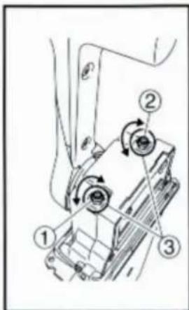

Throttle opening adjustment
The remote control box is capable of adjusting the throttle opening in the following manner:
- Loosen the screws securing the cover and remove it from the body.
- Loosen the locknut, and adjust the throttle opening by turning the stopper bolt. Turning the bolt clockwise decreases the throttle opening.
Turning the bolt counterclockwise increases the throttle opening.
① Stopper bolt on the reverse side
② Stopper bolt on the forward side
③ Lock nut
CAUTION:
Do not allow the stopper bolt to project 8 mm (0.3 in) or more from the nut surface. Otherwise, the stopper contacts the cover.
- After adjusting, tighten the locknut.
TIGHTENING TORQUE:
5–8 Nm (50–80 kgf·cm, 3.6–5.8 ft·lb)
Secure the cover to the body with the screws.
INSTALACJA SKRZYNKI ZDALNEGO STEROWANIA
Instalowanie kabli pilota
OSTROŻNOŚĆ:
- Loosen the five screws and remove the mounting flange, packing, and back plate.
NOTE:
The mounting flange on the back plate side should be removed.
① Mounting flange
② Back plate
③ Screws
- Screw the cable joint on to the remote control cable up to point "A" (11mm), and tighten the lock nuts. Before installing the cable joints, apply the water-resistant grease (Yamaha Grease A) to the threaded holes in the cable joints.
① Remote control cable
② Lock nut
③ Cable joint
TIGHTENING TORQUE:
1.5–1.8 Nm (15–18 kgf·cm, 1.1–1.3 ft·lb)
- Insert the shift cable into the housing clamp so that the groove on its end fits over the ridge in the clamp. Fit the cable joint over the pin on the end of the shift arm, and lock it with the circlip.
① Shift arm
② Circlip
③ Shift cable
④ Clamp groove
⑤ Grommet

- Fit the grommet in the clamp groove.

- Connect the throttle cable to the throttle arm in the same manner.
① Circlip
② Throttle cable
③ Shift cable

- Hold the back plate and mounting flange firmly with the five screws, and fit the packing in place.
① Mounting flange
② Back plate
③ Screws

- Secure the two remote control boxes with the three screws.
① Screw

- After installing the remote control cables, temporarily secure the remote control boxes to the predetermined position with the screws and nuts.
① Packing
② Remote control box
③ Screw
④ Hull
⑤ Washer
⑥ Nut

INSTALLING THE REMOTE CONTROL BOX

natural_image
Technical line drawing of a mechanical component with screws and mounting holes (no text or symbols)- Peel the paper off the back of packing, and adhere the packing to the boat hull so that the holes in the packing align with the remote control box mounting screw holes in the hull.

CONNECTING THE REMOTE CONTROL CABLE TO THE ENGINE
Checkpoints of cable joint
Shift:
Operate the control lever a few times and check to see that the shift lever on the engine side moves correctly.
Throttle:
Operate the control lever a few times and make sure that when it is returned to the neutral position the throttle lever on the engine side is set to the full-closed position.
Free accelerator:
Push the free accelerator button, and turn the control lever downward until it stops, then make sure that when it is returned to the neutral position, the free accelerator button is automatically reset.

Adjustment of cable joint
Adjust the cable joints on the engine side when the above checkpoints do not operate correctly.
CAUTION:
The cable joints on the engine side must be screwed onto the remote control cables at least 8 mm (0.3 in).
Adjust the cable joint on the remote control side if the adjustment cannot be made only on the engine side.

- After connecting the cables to the engine, move the control lever from lock to lock several times and check for good operation of the engine and remote control box.
- Firmly secure the remote control box (which is temporarily held with the screws) to the hull.
CAUTION:
Check that the cables are not sharply bent (less than 200 mm (7.87 in) in radius) or unnecessarily bent. (The number of bends should be minimized.) Also, check that no portions of the cables are clamped so hard as to deform the cable outers.
- Secure the cover to the body with the screws.

- Remove the two screws and remove the throttle lever assembly. Position the throttle lever assembly so that it faces downward and secure it with the two screws.
TIGHTENING TORQUE: 5–8 Nm (50–80 kgf·cm, 3.6–5.8 ft·lb)
1 Push-to-open throttle type
2 Pull-to-open throttle type
① Roller
② Throttle lever assembly
③ Stopper
④ Screws
- Align both the cam groove (for pull-to-open) in the dwell plate and the roller in the throttle lever assembly with the specific position, and lock the throttle arm assembly and dwell plate with the circlip.
NOTE:
Make sure the circlip are correctly fitted in place.
① Groove for push-to-open
② Groove for pull-to-open
③ Dwell plate
④ Roller
⑤ Throttle arm assembly
-
Secure the dwell plate retainer with the four screws.
-
Install the mounting flange, back plate with the five screws.
NOTE: \_\_\_\_
When installing the back plate, use care so that the wire harness is not pinched.
- Install the cover on the body.

VERIFYING CORRECT OPERATION
Be sure to verify that the remote control box operates correctly after installation.
- Follow the procedure for starting the engine and verify that the engine starts properly.
- Pull the lanyard to remove the lock plate from the engine stop lanyard switch and verify that the engine stops.
NOTE: \_\_\_\_
If the remote control box fails to operate correctly, verify that the installation procedure was followed properly.

NOTES ON STORAGE
To ensure a longer life of the remote control box, be sure to take the following steps when storing it for a long period of time.
- Remove the cable joints and apply water-resistant grease (Yamaha grease A) to the thread portion of the inner cable.
- Also apply water-resistant grease (Yamaha grease A) to inner parts of the remote control box, particularly to contact surfaces of moving parts. If any rust is found, remove it and apply the grease.
- Avoid bending the cables into a loop as much as possible. But if they have to be looped, the loop diameter should be more than one meter (40 in).
- Select a dry place for storage.

SWITCH PANEL MOUNTING

WARNING
When installing or removing electrical parts, be sure to disconnect the battery wires from the battery terminals. When connecting the battery wires to the battery terminals, be sure to turn off the main switch and remove the switch key. Otherwise you may receive an electric shock, or sparks may ignite the fuel causing an explosion.
CAUTION:
Install the switch panel onto the dashboard. Select a location allowing easy access from the helmsman's seat. If the boat has no dashboard, the switch panel should be installed in a location protected from water spray.
1 Switch panel for single engine
2 Switch panel for twin engine
- Cut a hole in the instrument panel as indicated in this mounting diagram. Using a 2-1/16-inch hole saw, make holes and then cut out the center portion as shown.
- Connect the wire harness to the switch panel assembly, and pass it back through the hole.
- Secure the switch panel assembly to the instrument panel with the bind screws, washers and nuts.


natural_image
Symbol of a trash bin with crossed lines indicating no waste or discharge, and a solid black rectangle below (no text or labels)PRAWIDŁOWA UTYLIZACJA
natural_image
Line drawing of a mechanical lever device (no text or symbols)HULP NODIG ? MET TAC TUS!
Qi ^15
10 11
12 :twee
Kunji]
STANDAARD
natural_image
Technical line drawing of a mechanical device with lever and base (no text or symbols)natural_image
Pure mechanical component diagram without any text, numbers, or symbolsSTANDARD

natural_image
Illustration of a hand using a tool to press or install a mechanical component with directional arrows (no text or symbols)SINGLE

natural_image
Simple line drawing of a device with a handle and circular button (no text or symbols)
natural_image
Diagram showing two hand positions of a device with a handle, no text or symbols present

Throttle opening adjustment
The remote control box is capable of adjusting the throttle opening in the following manner:
- Loosen the screws securing the cover and remove it from the body.
- Loosen the locknut, and adjust the throttle opening by turning the stopper bolt. Turning the bolt clockwise decreases the throttle opening.
Turning the bolt counterclockwise increases the throttle opening.
① Stopper bolt on the reverse side
② Stopper bolt on the forward side
③ Lock nut
CAUTION:
Do not allow the stopper bolt to project 8 mm (0.3 in) or more from the nut surface. Otherwise, the stopper contacts the cover.
- After adjusting, tighten the locknut.
TIGHTENING TORQUE:
5–8 Nm (50–80 kgf·cm, 3.6–5.8 ft·lb)
Secure the cover to the body with the screws.
ÿDE AFSTANDSBEDIENINGSKAST INSTALLEREN
- Loosen the five screws and remove the mounting flange, packing, and back plate.
NOTE:
The mounting flange on the back plate side should be removed.
① Mounting flange
② Back plate
③ Screws

- Screw the cable joint on to the remote control cable up to point "A" (11mm), and tighten the lock nuts. Before installing the cable joints, apply the water-resistant grease (Yamaha Grease A) to the threaded holes in the cable joints.
① Remote control cable
② Lock nut
③ Cable joint
TIGHTENING TORQUE:
1.5–1.8 Nm (15–18 kgf·cm, 1.1–1.3 ft·lb)

- Insert the shift cable into the housing clamp so that the groove on its end fits over the ridge in the clamp. Fit the cable joint over the pin on the end of the shift arm, and lock it with the circlip.
① Shift arm
② Circlip
③ Shift cable
④ Clamp groove
⑤ Grommet

- Fit the grommet in the clamp groove.

- Connect the throttle cable to the throttle arm in the same manner.
① Circlip
② Throttle cable
③ Shift cable

- Hold the back plate and mounting flange firmly with the five screws, and fit the packing in place.
① Mounting flange
② Back plate
③ Screws

- Secure the two remote control boxes with the three screws.
① Screw

- After installing the remote control cables, temporarily secure the remote control boxes to the predetermined position with the screws and nuts.
① Packing
② Remote control box
③ Screw
④ Hull
⑤ Washer
⑥ Nut

INSTALLING THE REMOTE CONTROL BOX

natural_image
Technical line drawing of a mechanical component with screws and mounting brackets (no text or symbols)- Peel the paper off the back of packing, and adhere the packing to the boat hull so that the holes in the packing align with the remote control box mounting screw holes in the hull.

CONNECTING THE REMOTE CONTROL CABLE TO THE ENGINE
Checkpoints of cable joint
Shift:
Operate the control lever a few times and check to see that the shift lever on the engine side moves correctly.
Throttle:
Operate the control lever a few times and make sure that when it is returned to the neutral position the throttle lever on the engine side is set to the full-closed position.

Free accelerator:
Push the free accelerator button, and turn the control lever downward until it stops, then make sure that when it is returned to the neutral position, the free accelerator button is automatically reset.
Adjustment of cable joint
Adjust the cable joints on the engine side when the above checkpoints do not operate correctly.
CAUTION:
The cable joints on the engine side must be screwed onto the remote control cables at least 8 mm (0.3 in).
Adjust the cable joint on the remote control side if the adjustment cannot be made only on the engine side.

- After connecting the cables to the engine, move the control lever from lock to lock several times and check for good operation of the engine and remote control box.
- Firmly secure the remote control box (which is temporarily held with the screws) to the hull.
CAUTION:
Check that the cables are not sharply bent (less than 200 mm (7.87 in) in radius) or unnecessarily bent. (The number of bends should be minimized.) Also, check that no portions of the cables are clamped so hard as to deform the cable outers.
- Secure the cover to the body with the screws.

WIJZIGEN VAN DE PUSH-TO-OPEN-GAS TYPE NAAR HET TREKKEN-TO-OPEN-GAS-TYPE
- Remove the two screws and remove the throttle lever assembly. Position the throttle lever assembly so that it faces downward and secure it with the two screws.
TIGHTENING TORQUE: 5–8 Nm (50–80 kgf·cm, 3.6–5.8 ft·lb)
1 Push-to-open throttle type
2 Pull-to-open throttle type
① Roller
② Throttle lever assembly
③ Stopper
④ Screws
- Align both the cam groove (for pull-to-open) in the dwell plate and the roller in the throttle lever assembly with the specific position, and lock the throttle arm assembly and dwell plate with the circlip.
NOTE:
Make sure the circlip are correctly fitted in place.
① Groove for push-to-open
② Groove for pull-to-open
③ Dwell plate
④ Roller
⑤ Throttle arm assembly
-
Secure the dwell plate retainer with the four screws.
-
Install the mounting flange, back plate with the five screws.
NOTE: \_\_\_\_
When installing the back plate, use care so that the wire harness is not pinched.
- Install the cover on the body.

VERIFYING CORRECT OPERATION
Be sure to verify that the remote control box operates correctly after installation.
- Follow the procedure for starting the engine and verify that the engine starts properly.
- Pull the lanyard to remove the lock plate from the engine stop lanyard switch and verify that the engine stops.
NOTE: \_\_\_\_
If the remote control box fails to operate correctly, verify that the installation procedure was followed properly.

NOTES ON STORAGE
To ensure a longer life of the remote control box, be sure to take the following steps when storing it for a long period of time.
- Remove the cable joints and apply water-resistant grease (Yamaha grease A) to the thread portion of the inner cable.
- Also apply water-resistant grease (Yamaha grease A) to inner parts of the remote control box, particularly to contact surfaces of moving parts. If any rust is found, remove it and apply the grease.
- Avoid bending the cables into a loop as much as possible. But if they have to be looped, the loop diameter should be more than one meter (40 in).
- Select a dry place for storage.

SWITCH PANEL MOUNTING

WARNING
When installing or removing electrical parts, be sure to disconnect the battery wires from the battery terminals. When connecting the battery wires to the battery terminals, be sure to turn off the main switch and remove the switch key. Otherwise you may receive an electric shock, or sparks may ignite the fuel causing an explosion.
CAUTION:
Install the switch panel onto the dashboard. Select a location allowing easy access from the helmsman's seat. If the boat has no dashboard, the switch panel should be installed in a location protected from water spray.
1 Switch panel for single engine
2 Switch panel for twin engine
- Cut a hole in the instrument panel as indicated in this mounting diagram. Using a 2-1/16-inch hole saw, make holes and then cut out the center portion as shown.
- Connect the wire harness to the switch panel assembly, and pass it back through the hole.
- Secure the switch panel assembly to the instrument panel with the bind screws, washers and nuts.


natural_image
Symbol of a trash bin with crossed lines indicating no waste or discharge, and a solid black rectangle below (no text or labels)CORRECTE VERWIJDERING
REP: Pooledas Group Ltd
natural_image
Line drawing of a mechanical lever device (no text or symbols)BEHÖVS HJÄLP ? MED TAC TUS!
Qi ^15
10 11
12 .två
Kunji]
STANDARD
natural_image
Technical line drawing of a mechanical lever assembly (no text or symbols)natural_image
Pure mechanical component diagram without any text, numbers, or symbolsSTANDARD
natural_image
Illustration of a hand using a tool to press or install a mechanical component, with arrows indicating motion (no text or symbols present)SINGLE

natural_image
Simple line drawing of a device with a button and scroll (no text or symbols)
natural_image
Diagram showing two hand positions of a device with a handle, no text or symbols present

Throttle opening adjustment
The remote control box is capable of adjusting the throttle opening in the following manner:
- Loosen the screws securing the cover and remove it from the body.
- Loosen the locknut, and adjust the throttle opening by turning the stopper bolt. Turning the bolt clockwise decreases the throttle opening.
Turning the bolt counterclockwise increases the throttle opening.
① Stopper bolt on the reverse side
② Stopper bolt on the forward side
③ Lock nut
CAUTION:
Do not allow the stopper bolt to project 8 mm (0.3 in) or more from the nut surface. Otherwise, the stopper contacts the cover.
- After adjusting, tighten the locknut.
TIGHTENING TORQUE:
5–8 Nm (50–80 kgf·cm, 3.6–5.8 ft·lb)
Secure the cover to the body with the screws.
ÿINSTALLERA FJÄRRKONTROLLBOXEN
- Loosen the five screws and remove the mounting flange, packing, and back plate.
NOTE:
The mounting flange on the back plate side should be removed.
① Mounting flange
② Back plate
③ Screws

- Screw the cable joint on to the remote control cable up to point "A" (11mm), and tighten the lock nuts. Before installing the cable joints, apply the water-resistant grease (Yamaha Grease A) to the threaded holes in the cable joints.
① Remote control cable
② Lock nut
③ Cable joint
TIGHTENING TORQUE:
1.5–1.8 Nm (15–18 kgf·cm, 1.1–1.3 ft·lb)

- Insert the shift cable into the housing clamp so that the groove on its end fits over the ridge in the clamp. Fit the cable joint over the pin on the end of the shift arm, and lock it with the circlip.
① Shift arm
② Circlip
③ Shift cable
④ Clamp groove
⑤ Grommet

- Fit the grommet in the clamp groove.

- Connect the throttle cable to the throttle arm in the same manner.
① Circlip
② Throttle cable
③ Shift cable
- Hold the back plate and mounting flange firmly with the five screws, and fit the packing in place.
① Mounting flange
② Back plate
③ Screws

- Secure the two remote control boxes with the three screws.
① Screw

- After installing the remote control cables, temporarily secure the remote control boxes to the predetermined position with the screws and nuts.
① Packing
② Remote control box
③ Screw
④ Hull
⑤ Washer
⑥ Nut

INSTALLING THE REMOTE CONTROL BOX

natural_image
Technical line drawing of a mechanical component with screws and mounting brackets (no text or symbols)- Peel the paper off the back of packing, and adhere the packing to the boat hull so that the holes in the packing align with the remote control box mounting screw holes in the hull.

CONNECTING THE REMOTE CONTROL CABLE TO THE ENGINE
Checkpoints of cable joint
Shift:
Operate the control lever a few times and check to see that the shift lever on the engine side moves correctly.
Throttle:
Operate the control lever a few times and make sure that when it is returned to the neutral position the throttle lever on the engine side is set to the full-closed position.

Free accelerator:
Push the free accelerator button, and turn the control lever downward until it stops, then make sure that when it is returned to the neutral position, the free accelerator button is automatically reset.
Adjustment of cable joint
Adjust the cable joints on the engine side when the above checkpoints do not operate correctly.
CAUTION:
The cable joints on the engine side must be screwed onto the remote control cables at least 8 mm (0.3 in).
Adjust the cable joint on the remote control side if the adjustment cannot be made only on the engine side.

- After connecting the cables to the engine, move the control lever from lock to lock several times and check for good operation of the engine and remote control box.
- Firmly secure the remote control box (which is temporarily held with the screws) to the hull.
CAUTION:
Check that the cables are not sharply bent (less than 200 mm (7.87 in) in radius) or unnecessarily bent. (The number of bends should be minimized.) Also, check that no portions of the cables are clamped so hard as to deform the cable outers.
- Secure the cover to the body with the screws.

- Remove the two screws and remove the throttle lever assembly. Position the throttle lever assembly so that it faces downward and secure it with the two screws.
TIGHTENING TORQUE: 5–8 Nm (50–80 kgf·cm, 3.6–5.8 ft·lb)
1 Push-to-open throttle type
2 Pull-to-open throttle type
① Roller
② Throttle lever assembly
③ Stopper
④ Screws
- Align both the cam groove (for pull-to-open) in the dwell plate and the roller in the throttle lever assembly with the specific position, and lock the throttle arm assembly and dwell plate with the circlip.
NOTE:
Make sure the circlip are correctly fitted in place.
① Groove for push-to-open
② Groove for pull-to-open
③ Dwell plate
④ Roller
⑤ Throttle arm assembly
-
Secure the dwell plate retainer with the four screws.
-
Install the mounting flange, back plate with the five screws.
NOTE: \_\_\_\_
When installing the back plate, use care so that the wire harness is not pinched.
- Install the cover on the body.

VERIFYING CORRECT OPERATION
Be sure to verify that the remote control box operates correctly after installation.
- Follow the procedure for starting the engine and verify that the engine starts properly.
- Pull the lanyard to remove the lock plate from the engine stop lanyard switch and verify that the engine stops.
NOTE: \_\_\_\_
If the remote control box fails to operate correctly, verify that the installation procedure was followed properly.

NOTES ON STORAGE
To ensure a longer life of the remote control box, be sure to take the following steps when storing it for a long period of time.
- Remove the cable joints and apply water-resistant grease (Yamaha grease A) to the thread portion of the inner cable.
- Also apply water-resistant grease (Yamaha grease A) to inner parts of the remote control box, particularly to contact surfaces of moving parts. If any rust is found, remove it and apply the grease.
- Avoid bending the cables into a loop as much as possible. But if they have to be looped, the loop diameter should be more than one meter (40 in).
- Select a dry place for storage.

SWITCH PANEL MOUNTING

WARNING
When installing or removing electrical parts, be sure to disconnect the battery wires from the battery terminals. When connecting the battery wires to the battery terminals, be sure to turn off the main switch and remove the switch key. Otherwise you may receive an electric shock, or sparks may ignite the fuel causing an explosion.
CAUTION:
Install the switch panel onto the dashboard. Select a location allowing easy access from the helmsman's seat. If the boat has no dashboard, the switch panel should be installed in a location protected from water spray.
1 Switch panel for single engine
2 Switch panel for twin engine
- Cut a hole in the instrument panel as indicated in this mounting diagram. Using a 2-1/16-inch hole saw, make holes and then cut out the center portion as shown.
- Connect the wire harness to the switch panel assembly, and pass it back through the hole.
- Secure the switch panel assembly to the instrument panel with the bind screws, washers and nuts.


natural_image
Symbol of a trash bin with crossed lines indicating no waste or discharge, and a solid black rectangle below (no text or labels)KORREKT AVFALLSHANTERING
UK REP: Pooledas Group Ltd
Enhet 5 Albert Edward House, The Pavilions Preston, Storbritannien
Tel: 01772418127 pooledas123@gmail.com

VEVOR®
TOUGH TOOLS, HALF PRICE