8M0059686 - Remote control Vevor - Free user manual and instructions
Find the device manual for free 8M0059686 Vevor in PDF.

| Product Type | Mechanical console remote control for outboard |
| Model | 8M0059686 |
| Brand | Vevor |
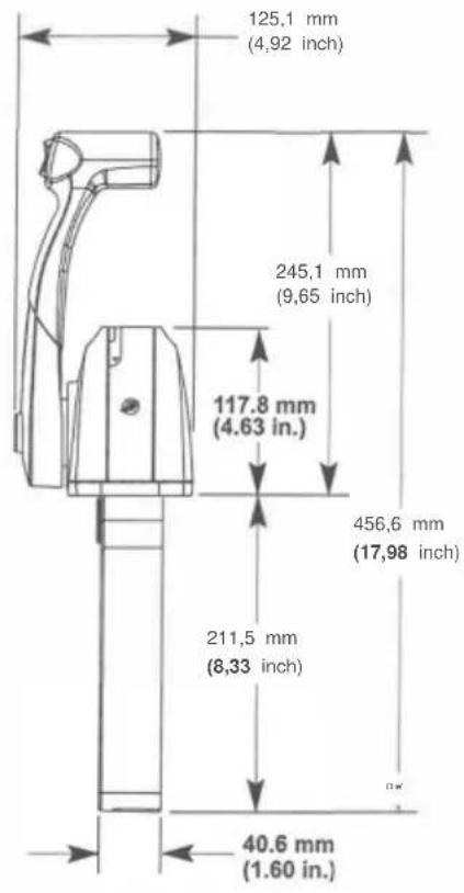
| Dimensions (H x L x P) | 456.6 x 245.1 x 211.5 mm (17.98 x 9.65 x 8.33 in) |
| Weight | Approximately 2.5 kg (varies depending on cables) |
| Material | Reinforced ABS plastic, metal (stainless steel for screws) |
| Power Supply | Mechanical (manual); electric switches for trim, neutral safety (12 V) |
| Main Functions | Throttle control, gear shifting (forward/reverse), electric trim switch, throttle-only button, neutral safety |
| Compatible Cable Type | Mercury/Quicksilver GEN II cables (shift and throttle) |
| Maximum Mounting Angle | 8° from perpendicular |
| Handle Torque | 17 Nm (150 lb·in) |
| Cable Screw Torque | 2.8 Nm (25 lb·in) |
| Back Plate Torque | 1.1 Nm (10 lb·in) |
| Bracket Torque | 4 Nm (35 lb·in) |
| Friction Adjustment | 11/32 in hex nut (turn clockwise to increase friction) |
| Recommended Lubrication | 2-4-C with PTFE (for cables) |
| Sealing | Not specified, but plan for installation in a dry location |
| Operating Temperature | From -20 °C to 60 °C (approximate) |
| Maintenance | Regularly check fasteners, lubricate cables, clean with a damp cloth |
| Safety | Mandatory neutral safety switch, remove propeller during engine tests |
| Spare Parts | Screws, nuts, brackets, cover, sleeves, control cables (available from Vevor) |
| Repairability | Modular, easy replacement of cables and components |
| General Information | Designed for Mercury, Mariner, Force outboard engines; requires professional installation |
Frequently Asked Questions - 8M0059686 Vevor
User questions about 8M0059686 Vevor
0 question about this device. Answer the ones you know or ask your own.
Ask a new question about this device
Download the instructions for your Remote control in PDF format for free! Find your manual 8M0059686 - Vevor and take your electronic device back in hand. On this page are published all the documents necessary for the use of your device. 8M0059686 by Vevor.
USER MANUAL 8M0059686 Vevor
Technical Support and E-Warranty Certificate www.vevor.com/support
We continue to be committed to provide you tools with competitive price. "Save Half", "Half Price" or any other similar expressions used by us only represents an estimate of savings you might benefit from buying certain tools with us compared to the major top brands and does not necessarily mean to cover all categories of tools offered by us. You are kindly reminded to verify carefully when you are placing an order with us if you are actually saving half in comparison with the top major brands.
VEVOR®
TOUGH TOOLS, HALF PRICE
OUTBOARD REMOTE
CONTROL BOX
MODEL: 8M0059686

natural_image
Exterior view of a handheld electric shock absorber with attached wires (no visible text or symbols)NEED HELP? CONTACT US!
Have product questions? Need technical support? Please feel free to contact us:
Technical Support and E-Warranty Certificate
www.vevor.com/support
This is the original instruction, please read all manual instructions carefully before operating. VEVOR reserves a clear interpretation of our user manual. The appearance of the product shall be subject to the product you received. Please forgive us that we won't inform you again if there are any technology or software updates on our product.
CONSOLE REMOTE CONTROL INSTALLATION AND OPERATION
| NOTICE |
| After completing installation, place these instructions with the product for the owner's future use. |
| NOTICE |
| This document is written to aid our dealers, boatbuilders, and company service personnel in the proper installation or service of our products. Persons who are not familiar with these or similar products produced by Mercury Marine, and who have not been trained in the recommended servicing or installation procedures should have the work performed by an authorized Mercury Marine dealer technician. Improper installation or servicing of the Mercury product could result in damage to the product or personal injury to the installer or persons operating the product. |
Console Remote Control
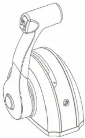
natural_image
Technical line drawing of a mechanical lever assembly (no text or symbols)Notice to Installer/Owner
Safety Alerts and Notices

Throughout this publication, "Warnings" and "Cautions," accompanied by the international HAZARD symbol ( ), are used to alert the technician to special instructions concerning a particular service or operation that may be hazardous if performed incorrectly or carelessly. Observe these safety alerts carefully.
These safety alerts alone cannot eliminate the hazards they signal. Strict compliance to these special instructions when performing the service, and common sense operation are major accident prevention measures.

WARNING
Indicates a hazardous situation which, if not avoided, could result in death or serious injury.

CAUTION
Indicates a hazardous situation which, if not avoided, could result in minor or moderate injury.
IMPORTANT: Indicates information or instructions that are necessary for a particular step or action.
NOTE: Indicates information that helps in the understanding of a particular step or action.
Selecting GEN II Remote Control Cables
Mercury - Mariner - Force - Mercury MerCruiser
Refer to the Mercury Precision Parts Accessories Guide for the available shift and throttle cables for your application. This control requires the use of Mercury/Quicksilver GEN II shift and throttle cables.
IMPORTANT: Remote control cables must be the correct length. Sharp bends on too-short of cables result in kinks. Too-long of cables require unnecessary bends and/or loops. Both conditions place extra stress on the cables.
IMPORTANT: Use 2-4-C with PTFE to lubricate the shift cable and throttle cable.
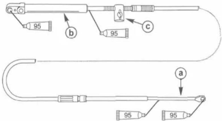
a - Remote control end
b - Engine end
c - Adjusting barrel
| Tube Ref No. | Description | Where Used | Part No. |
| 2-4-C with PTFE | Shift cable/throttle cable lubrication points | 92-802859A 1 |
NOTE: Allow for clearance of the cables directly behind the remote control. Cable radius at any one point must not be less than 305 mm (12 in.).
General Installation Information
IMPORTANT: The control handle friction adjustment must be made prior to installation.
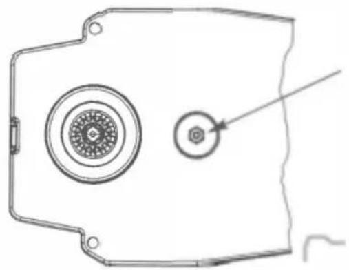
Control Handle Friction Adjustment
The control handle friction is preset from the factory. However, it can be adjusted.
- Use an 11/32 in. nut driver or socket wrench to carefully adjust the control handle friction. To increase friction, turn the adjusting nut clockwise. To decrease friction, turn the adjusting nut counterclockwise. IMPORTANT: Control handle friction is necessary for proper mechanical control operation. Insufficient friction may cause undesirable control arm operation.
natural_image
Technical line drawing of a mechanical component with circular features and a small inset view (no text or symbols)Reinstallation of Control Handle

WARNING
Improper installation can result in sudden, unexpected loss of throttle and shift control, resulting in serious injury or death. Install all control components properly.
- If the control handle is removed and reinstalled for any reason, apply Loctite 271 Threadlocker on the threads of the control handle retaining bolt.
- Tighten the control handle retaining bolt to the specified torque.
| Tube Ref No. | Description | Where Used | Part No. |
| Loctite271 Threadlocker | Control handle retaining bolt threads | 92-809819 |
| Description | Nm | lb-in. | lb-ft |
| Control handle retaining bolt | 17 | 150 | - |
Control Module Mounting
IMPORTANT: The control handle friction adjustment must be made prior to the installation of the remote control.
NOTE: The gasket and mounting base must be placed over the console control mount opening prior to installing the shift and throttle cables to the control module.
- Select the mounting area for the remote control. Select the template for the type of application. Follow the template directions when cutting and drilling the mounting surface.
- Connect the control cables and install the rear cover to the remote control. Refer to the Shift and Throttle Cable Installation in this instruction sheet.
- Install the remote control following the mounting instructions. Make necessary wiring connections by selecting the correct wiring diagram for the remote control model installed.
- Install and adjust the shift and throttle cables to the power package as outlined in the instructions which accompany the power package or refer to the Product Service Manual.
Final Checks and Adjustments
- Recheck the tightness of the control handle retaining bolt. Tighten to the specified torque.
| Description | Nm | lb-in. | lb-ft |
| Control handle retaining bolt | 17 | 150 | - |
- Before installing the back cover, recheck the throttle cable and shift cable retaining screws to ensure they are secure.
- Ensure the back cover screws are securely tightened.
- Before the remote control is securely fastened, verify the control cables and the control wiring harness are routed correctly.
NOTICE
Failure to rotate the propeller shaft when shifting gears or forcing the shift mechanism while the engine is not operating can result in product damage. If you must shift gears with the engine off, manually rotate the propeller shaft in the appropriate direction.
- Operate the control handle several times (see Notice preceding). Any binding or stiffness in the operation of the control handle is usually caused by the following:
a. Bends or tension on the control cables near the control.
b. Excessive number of bends in the cables.
c. Bends are too small in the cables.
d. Tight engine linkage.
e. Cable ties strapped too close to the control module.
f. Control handle friction adjustment.
g. Improper adjustment at the engine.
WARNING
Performing tests with the engine running may cause the propeller to rotate and result in serious injury or death. Use caution when performing a test that requires the engine running, and remove the propeller to avoid injury.
- Check the operation of the neutral start safety switch. The engine must only crank when the remote control is in the neutral position.
Required Mounting Clearance for Single Handle Remote Control
IMPORTANT: Ensure the remote control has adequate clearance and does not contact other components. The cable path should be free of obstructions. See shaded area.
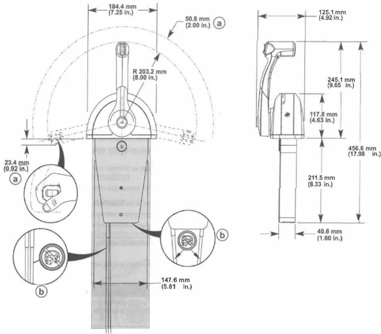
a - Hand clearance
b - If the shift and throttle cables are not mounted in the same housing slot position, do not use cable ties to secure the control cables - an increase in the shift and throttle load will be noticed
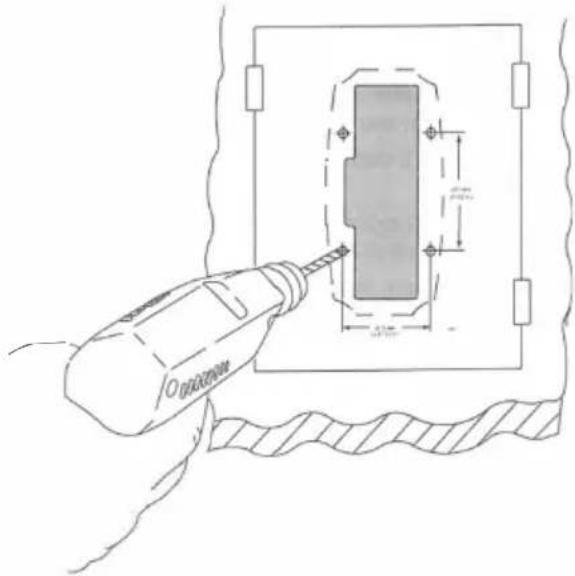
Drilling Mounting Area Location
IMPORTANT: When selecting mounting area for the remote control, the area directly behind the mounting panel must have sufficient clearance for control module, wiring harness, control cables, and control cable movement. Refer to the required mounting clearances.
IMPORTANT: Allow sufficient clearance for the handle movement to avoid interference with boat components or other accessories. Ensure the control handle clears the dash, seats, steering wheel, and any other obstructions when rotating the control handle.
- Remove the cutout template page located at the end of these installation instructions.
- Ensure the area of the boat where the remote control will be mounted is clear of obstructions and wiring prior to drilling the mounting area.
-
Place the cutout template onto the control mounting surface. Secure the cutout template to the desired location with adhesive tape.
IMPORTANT: Before drilling the mounting holes to 9.5 mm (0.375 in.) to accommodate the use of well nuts, ensure the thickness of the mounting area does not exceed the gripping range of the well nuts used. If the thickness is beyond the gripping range of the well nuts, drill the mounting holes to the correct diameter of a common flange head type screw. -
Drill and cut the mounting area as directed on the cutout template.
-
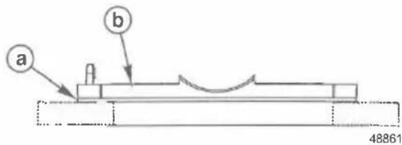
The control module can be rotated 8° from perpendicular relative to the remote control mounting surface. An 8° undercut must be made to the mounting location to allow for adequate clearance for the control module.
-
After cutting out the mounting area, remove all sharp edges with a suitable tool.
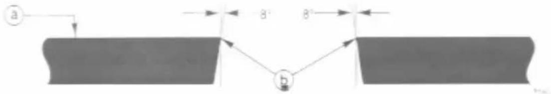
a - Control mounting surface
b - 8 ° undercut
Shift and Throttle Cable Installation
Control Cable Anchor Attaching Location
| Outboard Models (U.S. and Belgium Models Only) | Starboard Mount Control | Port Mount Control | ||
| Anchor Attaching Location | Anchor Attaching Location | |||
| Shift Cable | Throttle Cable | Shift Cable | Throttle Cable | |
| Force Outboards (except 9.9 and 15) | 4 | 2 3 2 | ||
| Mercury and Mariner Outboards (standard rotation gearcase and standard pull throttle) | 4 | 2 | 3 | 2 |
| Mercury and Mariner Outboards (with push throttle) | 4 | 1 | 3 1 | |
Mercury and Mariner Outboards (counterrotation gearcase with shift direction as shown)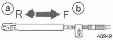 a - Reverse gearb - Forward gear a - Reverse gearb - Forward gear | 4 2 3 | 2 | ||
Mercury and Mariner Outboards (counterrotation gearcase with shift direction as shown)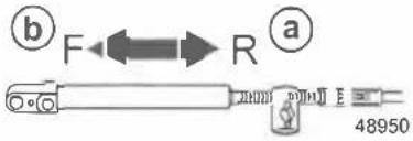 a - Reverse gearb - Forward gear a - Reverse gearb - Forward gear | 3 | 2 | 4 | 2 |
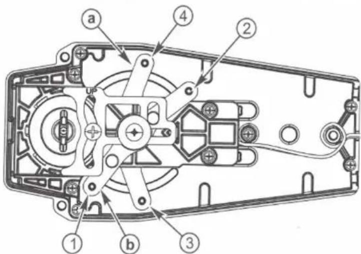
a - Shift arm
b - Throttle arm
NOTE: The gasket and mounting base must be placed over the console control mount opening prior to installing the shift and throttle cables to the control module.
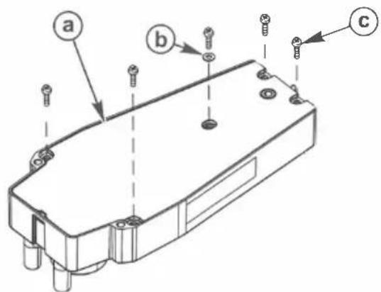
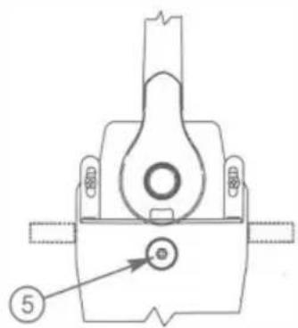
- Remove the screws securing the back plate to the control module.
a - Back plate
b - Washer
c - Screw (5)
IMPORTANT: Determine the type of drive unit rotation the cable is installed onto. The shift cable must be correctly installed at the remote control assembly for the appropriate drive unit rotation; standard or counterrotation.
NOTE: For Bravo Three, Blackhawk Drive, and for Outboard models 3.0 Liter EFI GEN II, OptiMax GEN II units, refer to the instructions for standard rotation control cable installation.
- Mercury MerCruiser Models Standard Rotation - The control cable must be installed in the remote control so the cable end will move in the direction of X when the shift handle is placed in the forward position.
- Mercury MerCruiser Models Counterrotation - The control cable must be installed in the remote control so the cable end will move in the direction of Y when the shift handle is placed in the forward position.
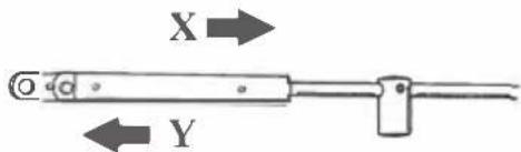
Direction of arrow (viewed at shift plate)
| Mercury MerCruiser Models | Standard Rotation | Counterrotation | ||
| Starboard Mount Mechanical Control | Anchor Attaching Location | Anchor Attaching Location | ||
| Shift Cable | Throttle Cable | Shift Cable | Throttle Cable | |
| Direction of arrow | X | X | Y | X |
| Lever number | 4 | 2 | 3 | 2 |
Typical Shift and Throttle Cable Installation, Outboard and Mercury MerCruiser
WARNING
Improper installation can result in sudden, unexpected loss of throttle and shift control, resulting in serious injury or death. Install all control components properly.
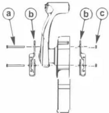
- Apply Loctite 271 Threadlocker to the threads of the cable fastener screws.
-
Install the control cables in the appropriate arm in the remote control module.
-
Tighten the cable fastener screws to the specified torque.
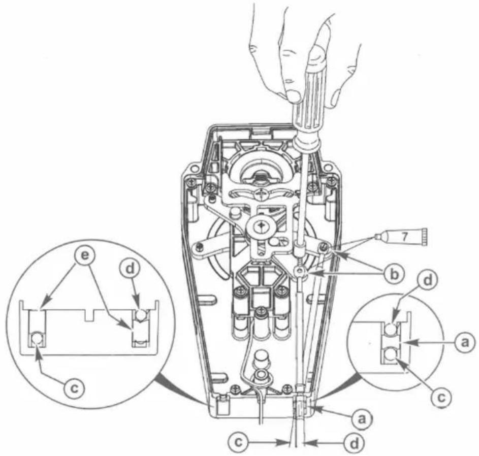
a - Small spacer
b - Screw
c - Shift cable
d - Throttle cable
e - Large spacer
| Tube Ref No. | Description | Where Used | Part No. |
| Loctite271 Threadlocker | Control cable fastener screw threads | 92-809819 |
| Description | Nm | lb-in. | lb-ft |
| Control cable fastener screws | 2.8 | 25 |
- After installing the control cables, secure the back plate with five washers and screws. Tighten the screws to the specified torque.
WARNING
Improper installation can result in sudden, unexpected loss of throttle and shift control, resulting in serious injury or death. Install all control components properly.
a - Back plate
b - Washer
c - Screw (5)
| Description | Nm | lb-in. | lb-ft |
| Back plate screws (5) | 1.1 | 10 |
Mounting the Remote Control
Single Handle Console Control Models
NOTE: The gasket and mounting base must be placed over the console control mount opening prior to installing the shift and throttle cables to the control module.
- Place the gasket and mounting base over the console control mount opening prior to installing the shift and throttle cables to the control module.
a - Gasket
b - Mounting base
- Install the mounting brackets to the control module with two 57 mm (2.0 in.) screws and locknuts. Do not tighten the screws at this time.
a - Screw (2), 57 mm (2.0 in.)
b - Mounting bracket (2)
c - Locknut (2)
- Place the control module assembly in the mounting cutout and select the desired angle of the control handle relative to the mounting surface. The maximum angle is 8^ from perpendicular. After the angle of the handle is selected, secure the mounting brackets with the screws and locknuts. Tighten the screws to the specified torque.
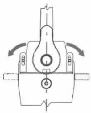
natural_image
Mechanical component diagram showing a lever mechanism with rotating arrows (no text or symbols)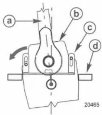
a - Control handle in neutral detent
b - Control module assembly mounted at 8° from perpendicular
c - Mounting bracket
d - Mounting panel
| Description | Nm | lb-in. | lb-ft |
| Mounting bracket screws and locknuts | 4 | 35 | - |
- Adjust the control handle friction to the desired resistance.
• Turn the control friction adjustment nut clockwise to increase the resistance.
• Turn the control friction adjustment nut counterclockwise to decrease the resistance.
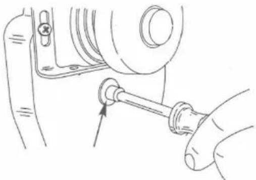
natural_image
Mechanical assembly diagram showing a shaft and bearing assembly (no text or labels)- Install a cable tie anchor onto the mounting screw located at the right side of the handle.
- Secure the remote control module assembly to the console with four mounting screws 38 mm (1.5 in.). Tighten the screws securely. IMPORTANT: Ensure the trim switch wire harness has enough slack so that it will move freely with the full range of the control handle.
- Provide the needed slack in the trim switch wire harness and then fasten the trim switch wire harness to the cable tie anchor with a cable tie.
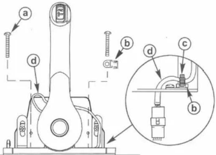
a - Screw (4)
b - Cable tie anchor
c - Cable tie
d - Trim switch wire harness
- Install the spacer on top of the remote control.

natural_image
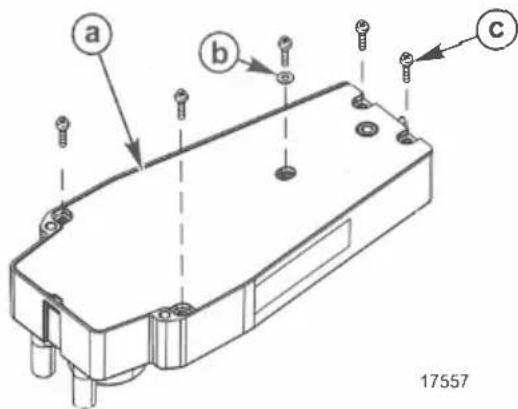
Technical line drawing of a mechanical device with no visible text or symbols- Hook the rear of the cover into the base and fasten the front of the cover to the base with a screw. Tighten the screw securely.
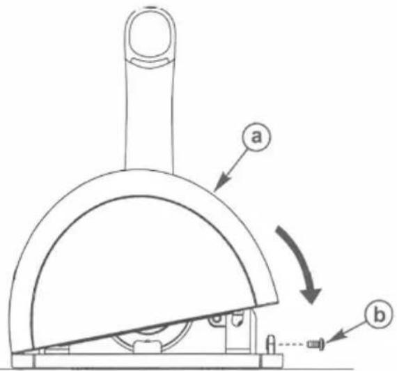
a - Cover
b - Screw
- Connect the remote control neutral start safety switch leads to the correct wire connections. Refer to Wiring Diagrams.
! WARNING
Starting the engine with the drive in gear can cause serious injury or death. Never operate a boat that does not have a neutral-safety-protection device.
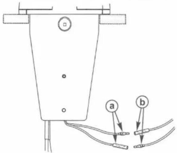
a - Neutral start safety switch leads
b - Wire connections
Wire Color Code Abbreviations
| Wire Color Abbreviations | ||||
| BLK | Black | BLU | Blue | |
| BRN | Brown | GRY | Gray | |
| GRN | Green | ORN or ORG | Orange | |
| PNK Pink | PPL or PUR | Purple | ||
| RED | Red | TAN | Tan | |
| WHT | White | YEL | Yellow | |
| LT or LIT Light | DK or DRK | Dark | ||
Wiring Diagrams
Single Outboard
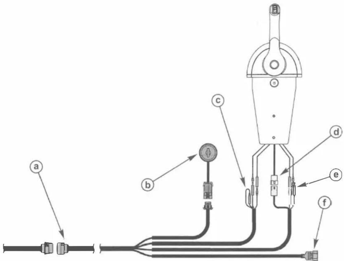
a - 14-pin connector
b - Ignition key switch
c - Lanyard connection for MCM models
d - Power trim connector
e - Neutral start safety switch leads
f - Analog gauge harness
Single Mercury MerCruiser - Gasoline Models
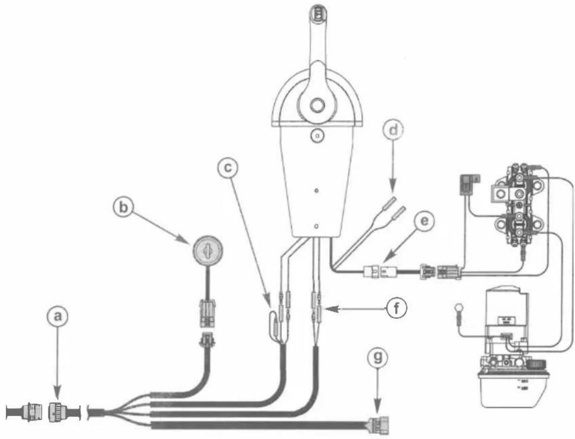
a - 14-pin connector
b - Ignition key switch
c - Lanyard connection for MCM models
d - Trim limit switch
e - Power trim harness connector
f - Neutral start safety switch leads
9 - Analog gauge harness
Single Mercury MerCruiser - Diesel Models D3.0L/150, D3.6L/180, D4.2L/220
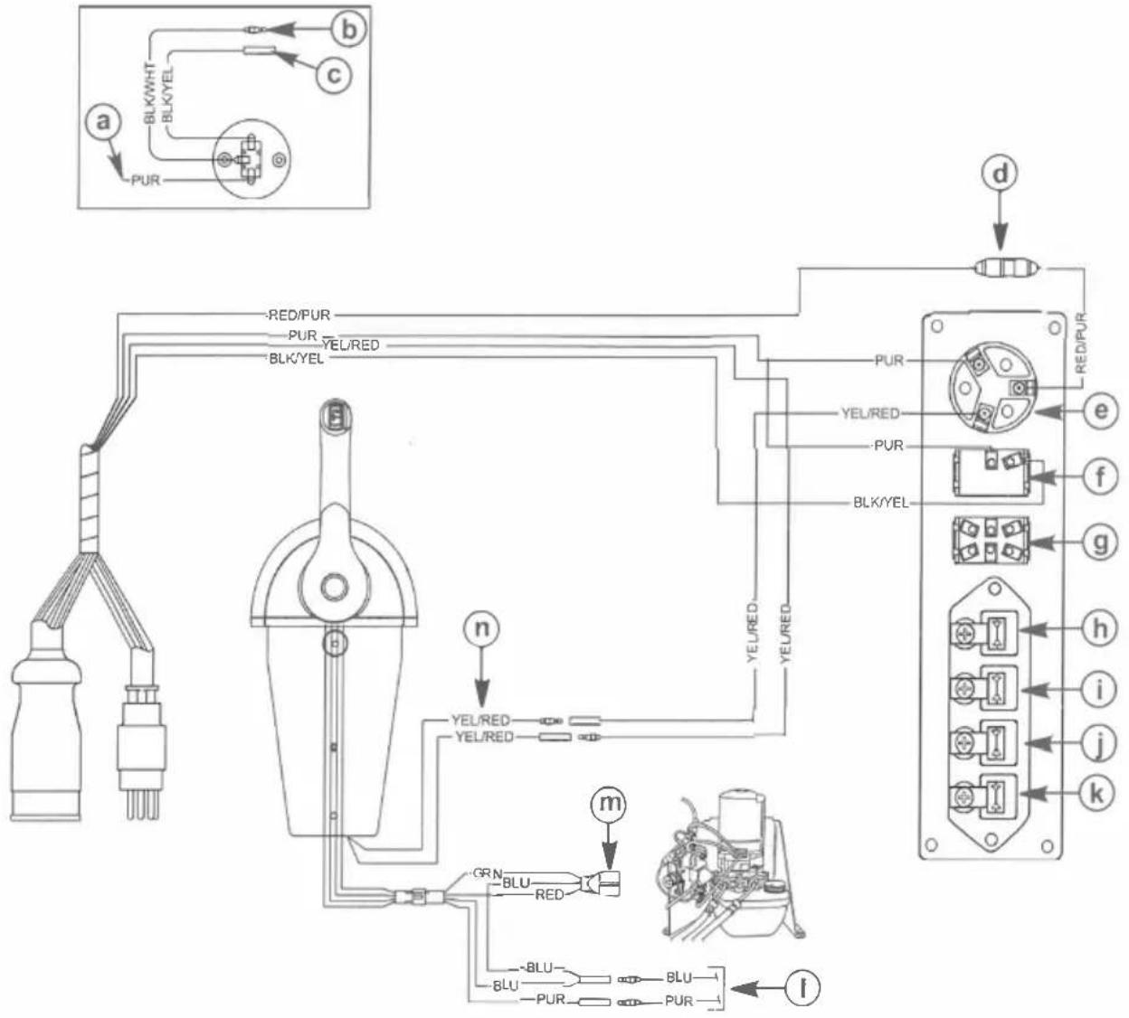
a - 12 volt source
b - Preheat
c - Alternator
d - Fuse
e - Ignition key switch
f - Stop switch
g - Light switch and audio test
h - Preheat indicator
i - Alternator indicator
j- Oil pressure indicator
k - Coolant temperature indicator
I - To trim limit switch
m- Power trim harness connector
n - Neutral start safety switch leads
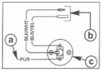
Single Mercury MerCruiser - Diesel Model D7.3L/270
flowchart
graph TD
    a["Component a"] --> BLK/WHT["BLK/WHT"]
    BLK/WHT --> BLK/YEL["BLK/YEL"]
    BLK/YEL --> BLK/WHT
    BLK/YEL --> BLK/WHT
    BLK/YEL --> BLK/WHT
    BLK/YEL --> BLK/WHT
    BLK/WHT --> b["Component b"]
    BLK/YEL --> BLK/WHT
    BLK/YEL --> BLK/WHT
    BLK/YEL --> BLK/WHT
    BLK/YEL --> BLK/WHT
    BLK/YEL --> BLK/WHT
    BLK/YEL --> BLK/WHT
    BLK/YEL --> BLK/WHT
    BLK/YEL --> BLK/WHT
    BLK/YEL --> BLK/WHT
    BLK/YEL --> BLK/WHT

    subgraph Component a
        A
        B
        C
    end

    subgraph Component b
        B
        C
        D
        E
        F
        G
        H
        I
        J
        K
        L
        M
        N
        O
        P
        Q
        R
        S
        T
        U
        V
        W
        X
        Y
        Z
        AA
        AB
        AC
        AD
        AE
        AF
        AG
        AH
        AI
        AJ
        AK
        AL
        AM
        AN
        AO
        AP
        AQ
        AR
        AS
        AT
        AU
        AV
        AW
        AX
        AY
        AZ
        BA
        BB
        BC
        BD
        BE
        BF
        BG
        BH
        BI
        BJ
        BK
        BL
        BM
        BN
        BO
        BP
        BPB
        BPB2
        BPB3
        BPB4
        BPB5
        BPB6
        BPB7
        BPB8
        BPB9
        BPB10
        BPB11
        BPB12
        BPB13
        BPB14
        BPB15
        BPB16
        BPB17
        BPB18
        BPB19
        BPB20
        BPB21
        BPB22
        BPB23
        BPB24
        BPB25
        BPB26
        BPB27
        BPB28
        BPB29
        BPB30
    end
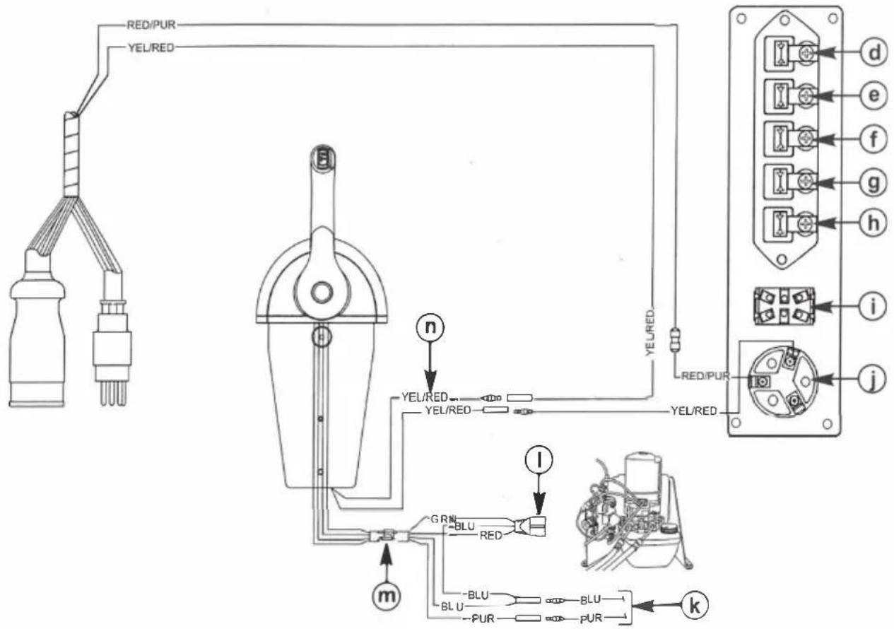
a - 12 volt source
b - Lanyard stop switch leads
c - Lanyard stop switch
d - Water in fuel indicator
e - Coolant temperature indicator
f - Oil pressure indicator
g - Alternator indicator
h - Preheat indicator
i - Light switch and audio test
j- Ignition key switch
k - To trim limit switch
| - Power trim harness connector
m - Plastic connector
n - Neutral start safety switch leads
Features and Operation
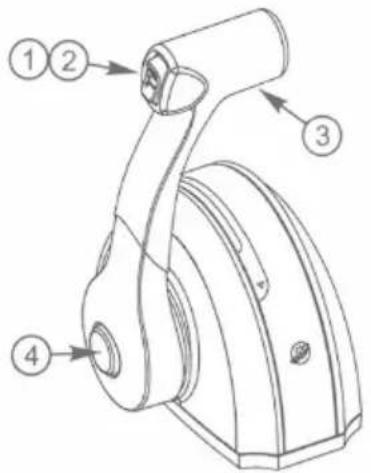
- Power trim switch (if equipped) - Used to trim or raise drive unit for trailering, launching, beaching, or shallow water operation. Refer to the Operation and Maintenance Manual for detailed power trim/tilt operating procedures.
- Trailer switch (if equipped) - Used to raise the drive unit beyond the maximum trim position. Refer to the Operation and Maintenance Manual for detailed trailer switch operation.
- Control handle - Operation of the shift and throttle are controlled by the movement of the control handle. Push the control handle forward from neutral with a quick firm motion to the first detent for forward gear. Continue pushing forward to increase speed. Pull the control handle back from neutral with a quick firm motion to the first detent for reverse gear. Continue pulling back to increase speed.
NOTICE
Failure to rotate the propeller shaft when shifting gears or forcing the shift mechanism while the engine is not operating can result in product damage. If you must shift gears with the engine off, manually rotate the propeller shaft in the appropriate direction.
- Throttle only button - Allows the engine throttle advancement without shifting the engine. This is done by disengaging the shift mechanism from the control handle. The throttle only button can be depressed only when the remote control handle is in the neutral position and should only be used to assist in starting the engine. Refer to the Operation and Maintenance Manual for correct throttle setting for starting the engine.
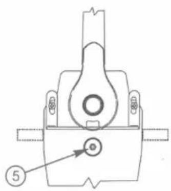
- Control handle throttle friction adjustment nut - This nut can be adjusted to increase or decrease the friction on the control handle. This will help prevent creep of the remote control handle. Turn the nut clockwise to increase friction and counterclockwise to decrease friction. Adjust to the desired friction.
Single Handle Mounting Template
IMPORTANT: Due to printing variables, the image may have changed from the actual size. Check this template with the mounting base before drilling or cutting the mounting surface, or use the mounting base as a guide to mark the mounting surface.
Drill the holes and cutout the shaded area.
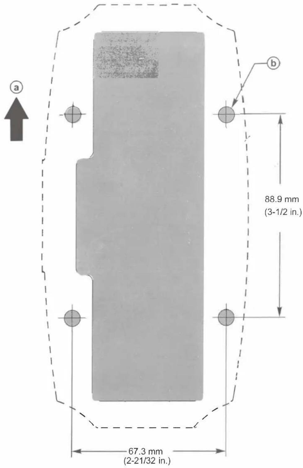
a - Front of boat
b - Drill to the correct diameter for the fasteners used
Products of Mercury Marine
W6250 Pioneer Road
Alpha, Axius, Bravo One, Bravo Two, Bravo Three, Circle M with Waves Logo, K-planes, Mariner, MerCathode, MerCruiser, Mercury, Mercury with Waves Logo, Mercury Marine, Mercury Precision Parts, Mercury Propellers, Mercury Racing, MotorGuide, OptiMax, Quicksilver, SeaCore, Skyhook, SmartCraft, Sport-Jet, Verado, VesselView, Zero Effort, Zeus, and #1 On the Water are registered trademarks of Brunswick Corporation. Mercury Product Protection is a registered service mark of Brunswick Corporation
| No | Components Picture Qty | ||
| 1 | Screw(M5*55) 2 | 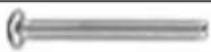 | |
| 2 | Nut(M5) 2 | ||
| 3 | Rubber sleeve and screw(M5*40) | 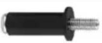 | 4 |
| 4 | Screw(M4*8) 2 |  | |
| 5 | Washer |  | 2 |
| 6 | Screw(M4 *7) |  | 1 |
| 7 | Plug | [X60Z] | 1 |
| 8 | Insulated terminal sleeve 1 1 |  | |
| 9 | Insulated terminal sleeve 2 1 |  | |
| 10 | Terminal(Male a18nd female) |  | 2 |
| 11 | Tie holder |  | 1 |
| 12 | Cable tie holder 1 |  | 1 |
| 13 | Cable tie holder 2 |  | 2 |
| 14 | Cable tie |  | 3 |
| 15 | Mounting bracket | 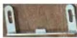 | 2 |
| 16 | Cover |  | 1 |
| 17 | Decorative seat |  | 1 |
| 18 | Rubber buckle |  | 1 |
| 19 | Use Manual | 1 |
natural_image
Symbol of a trash bin with crossed lines and a solid black rectangle below (no text or numbers)CORRECT DISPOSAL
This product is subject to the provision of European Directive 2012 19 EU. The symbol showing a wheeliebin crossed through indicates that the product requires separate use collection in the European Union. This applies to the product and all accessories marked with this symbol. Productsmarked as such may not be discarded with normal domestic waste, but must be taken to acollection point or recycling electrical and electronic devices.
Address: Baoshanqu Shuangchenglu 803long 11hao 1602A-1609shi Shanghai Imported to AUS: SIHAO PTY LTD.1 ROKEVA STREETEASTWOOD NSW 2122 Australia Imported to USA: Sanven Technology Ltd. Suite 250, 9166 Anaheim Place, Rancho Cucamonga, CA 91730
EC REP : SHUNSHUN GmbH.
Römeräcker 9 Z2021,76351 Linkenheim-Hochstetten, Germany
Tel: +49 1727041930 euvertreter@gmail.com
UK REP: Pooledas Group Ltd
Unit 5 Albert Edward House, The Pavilions Preston, United Kingdom
Tel: 01772418127 pooledas123@gmail.com
VEVOR®
TOUGH TOOLS, HALF PRICE
Technical Support and E-Warranty Certificate
www.vevor.com/support
VEVOR®
OUTILS ROBUSTES, À MOITIÉ PRIX
natural_image
Exterior view of a mechanical device with black handle and wiring, no visible text or symbolsBESOIN D'AIDE? CONTACTEZ-NOUS!
natural_image
Technical line drawing of a mechanical component with no visible text or symbolsnatural_image
Pure technical line drawing of a mechanical part with no text, numbers, or symbolsa. Drie de claringement, de «desse
b - Papillon des gaz ar111
natural_image
Simple line drawing of a mechanical lever or rod with a handle and base, labeled '.et' below (no text or symbols on the diagram itself)natural_image
Technical line drawing of a mechanical device with no visible text or symbolsINSTALLATION ET FONCTIONNEMENT DE LA TÉLÉCOMMANDE DE LA CONSOLE

natural_image
Symbol of a trash bin with crossed lines indicating no waste, and a solid black rectangle below (no text or labels)ÉLIMINATION CORRECTE
Technical Support and E-Warranty Certificate
www.vevor.com/support
VEVOR®
ROBUSTE WERKZEUGE, ZUM HALBEN PREIS
natural_image
Exterior view of a mechanical device with black handle and wiring, no visible text or symbolsBRAUCHEN SIE HILFE? KONTAKTIERE UNS!
www.vevor.com/support
natural_image
Technical line drawing of a mechanical component with no visible text or symbolsnatural_image
Technical line drawing of a mechanical device with no visible text or symbolsINSTALLATION UND BETRIEB DER KONSOLENFERNBEDIENUNG
eine Deckung
b - Schraube

natural_image
Symbol of a trash bin with crossed lines indicating no waste, and a solid black rectangle below (no text or labels)RICHTIGE ENTSORGUNG
REP: Pooledas Group Ltd
Technical Support and E-Warranty Certificate
www.vevor.com/support
VEVOR®
STRUMENTI RESISTENTI, METÀ PREZZO
natural_image
Exterior view of a mechanical device with black handle and wiring, no visible text or symbolsHO BISOGNO DI AIUTO? CONTATTACI!
natural_image
Technical line drawing of a mechanical component with no visible text or symbolsa - Piastra posteriore
b - Rondella c -
Vite (5)
natural_image
Technical line drawing of a mechanical device with no visible text or symbols
natural_image
Symbol of a trash bin with crossed lines indicating no waste, and a solid black rectangle below (no text or labels)REP UK: Pooledas Group Ltd
Technical Support and E-Warranty Certificate
www.vevor.com/support
VEVOR®
HERRAMIENTAS RESISTENTES A MITAD DE PRECIO
natural_image
Exterior view of a mechanical device with black handle and wiring, no visible text or symbolsnatural_image
Technical line drawing of a mechanical component with no visible text or symbolsnatural_image
Pure technical line drawing of a mechanical part with no text, numbers, or symbolsa - Placa trasera b - Arandela c - Tomillo (5)
natural_image
Technical line drawing of a mechanical device with no visible text or symbolsuna tapa b-tornillo

natural_image
Symbol of a trash bin with crossed lines indicating no waste, and a solid black rectangle below (no text or labels)Technical Support and E-Warranty Certificate
www.vevor.com/support
VEVOR®
WYTRZYMAŁE NARZĘDZIA, ZA PÓŁ CENY
natural_image
Exterior view of a mechanical device with black handle and wiring, no visible text or symbolsPOTRZEBUJE POMOCY? SKONTAKTUJ SIĘ Z NAMI!
natural_image
Technical line drawing of a mechanical component with no visible text or symbolsnatural_image
Pure technical line drawing of a mechanical part with no text, numbers, or symbolsnatural_image
Technical line drawing of a mechanical device with no visible text or symbolsINSTALACJA I OBSŁUGA PILOTA DO KONSOLI

natural_image
Symbol of a trash bin with crossed lines indicating no waste, and a solid black rectangle below (no text or labels)PRAWIDŁOWA UTYLIZACJA
Technical Support and E-Warranty Certificate
www.vevor.com/support
VEVOR®
STERK GEREEDSCHAP, HALVE PRIJS
Technische ondersteuning en e-garantiecertificaat www.vevor.com/support
BUITENBOORDMOTOR AFSTANDSBEDIENING
MODEL: 8M0059686
natural_image
Exterior view of a mechanical device with black handle and wiring, no visible text or symbolsHULP NODIG? NEEM CONTACT MET ONS OP!
natural_image
Technical line drawing of a mechanical component with no visible text or symbolsKennisgeving aan installateur/eigenaar
a• Schakelarm
b - Gashendel ar111
a - Schroef (4) b
- Kabelbinderanker c-
Kabelbinder
natural_image
Technical line drawing of a mechanical device with no visible text or symbolsINSTALLATIE EN BEDIENING VAN DE CONSOLE-AFSTANDSBEDIENING
een dekmantel
b - Schroef
a - 14-pins connectorÿ
b - Contactsleutelschakelaar

natural_image
Symbol of a trash bin with crossed lines indicating no waste, and a solid black rectangle below (no text or labels)CORRECTE VERWIJDERING
REP: Pooledas Group Ltd
Technical Support and E-Warranty Certificate
www.vevor.com/support
VEVOR®
TÅRA VERKTYG, HALVA PRISET
natural_image
Exterior view of a mechanical device with black handle and wiring, no visible text or symbolsBEHÖVS HJÄLP? KONTAKTA OSS!
natural_image
Technical line drawing of a mechanical component with no visible text or symbolsa - Bakplatta b - Bricka c - Skruv (5)
a - Liten distans
b- Skruv
C - Växelkabel
d - Gaskabel
e - Stort mellanlägg
natural_image
Technical line drawing of a mechanical device with no visible text or symbolsKONSOL FJÄRRKONTROLL INSTALLATION OCH ANVÄNDNING
a - Omslag b - Skruv
natural_image
Symbol of a trash bin with crossed lines indicating no waste, and a solid black rectangle below (no text or labels)KORREKT AVFALLSHANTERING
UK REP: Pooledas Group Ltd
Enhet 5 Albert Edward House, The Pavilions Preston, Storbritannien
Tel: 01772418127 pooledas123@gmail.com
VEVOR®
TOUGH TOOLS, HALF PRICE
Technical Support and E-Warranty Certificate
www.vevor.com/support