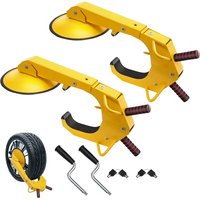
WBS-010 - Toys Vevor - Free user manual and instructions
Find the device manual for free WBS-010 Vevor in PDF.


User questions about WBS-010 Vevor
0 question about this device. Answer the ones you know or ask your own.
Ask a new question about this device
Download the instructions for your Toys in PDF format for free! Find your manual WBS-010 - Vevor and take your electronic device back in hand. On this page are published all the documents necessary for the use of your device. WBS-010 by Vevor.
USER MANUAL WBS-010 Vevor
Technical Support and E-Warranty Certificate www.vevor.com/support
WHEEL ALIGNMENT SYSTEM
MODEL:WBS-010
We continue to be committed to provide you tools with competitive price. "Save Half", "Half Price" or any other similar expressions used by us only represe estimate of savings you might benefit from buying certain tools with us compared to t top brands and does not necessarily mean to cover all categories of tools offered by are kindly reminded to verify carefully when you are placing an order with us if yo actually saving half in comparison with the top major brands.
VEVOR®
TOUGH TOOLS, HALF PRICE
WHEEL ALIGNMENT SYSTEM
MODEL:WBS-010
NEED HELP? CONTACT US!
Have product questions? Need technical support? Please feel free contact us:
Technical Support and E-Warranty Certificate www.vevor.com/support
This is the original instruction, please read all manual instructions carefully before operating. VEVOR reserves a clear interpretation of user manual. The appearance of the product shall be subject to the product you received. Please forgive us that we won't inform you there are any technology or software updates on our product.
IMPORTANT SAFEGUARDS

WARNING: Read and understand this entire manual before operating or servicing this product. Failure to follow these warnings and instructions can cause personal injury or damage to valuable property.
-
Avoid children using the wheel alignment system. And this is not a toy. Do not allow children to play.
-
Keep away from sharp points, blades and other items.
Assembly precautions -
Assemble only according to these instructions. Improper assembly can create hazards.
- Wear ANSI-approved safety goggles and heavy-duty work gloves during assembly.
- Keep assembly area clean and well-lit.
- Keep bystanders out of the area during assembly.
- Do not assemble when tired or when under the influence of alcohol, drugs or medication.
- Product capabilities apply to properly and completely assembled products only.
- For additional information regarding the parts listed in the following pages, please refer to the Assembly Diagram of this manual. Unwrap and separate all parts in a clean work area. Please keep small spare parts of children's reach.
SAVE THESE INSTRUCTIONS
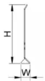
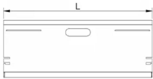
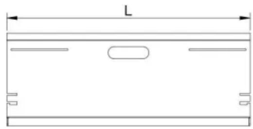
PRODUCT SPECIFICATIONS:
| Model | L (mm) | H (mm) | W (mm) |
| WBS-010 | 580 | 211 | 35 |
PACKAGE INCLUDE
| No | Components | Picture | Q'ty |
| 1 | Tape measure | 2pcs | |
| 2 | Hexagon stud | 4pcs | |
| 3 | black thumb screws | 8pcs | |
| 4 | flat washer | 8pcs | |
| 5 | rubber grippers | 4pcs | |
| 6 | magnet | 2pcs | |
| 7 | Angle comparison table | THE PLATE WORMS TO INCH CONVERSION CHART Example of the vehicle speed, specifically for the two side by side between 10° and 50° measured by the two planes. | |
| ### | 1pcs | ||
SIMPLE INSTRUCTION
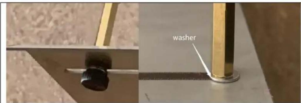
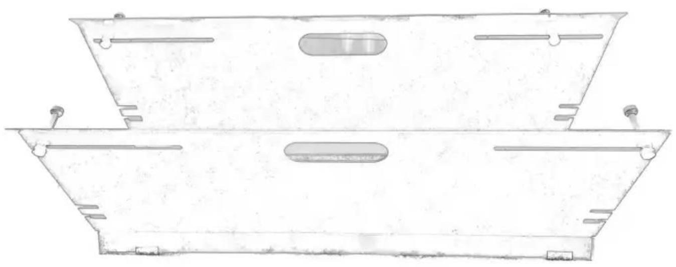
Step 1: Install support studs.
Use the 8 thumb screws to attach them to the plates as desired. Place 8 pads on the thumb screw and prop screw sides as shown.
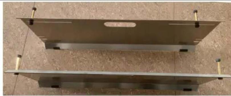
Step 2: Bolt on the upper contact point.
One washer sits between the chassis of the gauge and the threaded shaft. small backing plate threads on the backside. To adjust the position of the contact point only the threaded shaft needs to be turned, the chassis of the gauge will prevent the backing plate from turning.
Assembly should now be complete
Toe Plates Toe Measurement Instructions
The rim stand-offs work on nearly all cars and suv's, however it is possible that sidewall on some trucks and suv's may be too tall for the stand-offs to properly contact the wheel rim. In this case either the stand-offs can be removed and the plates can be used as standard toe plates (placed flat against the tire). Or you use two pads of the same height and place under the plates to raise them up higher.
Before you start ensure the vehicle's steering wheel is centered. If they vehicle is equipped with hub caps they will either need to be removed.
Step 1: Adjust flat slot plate
Place the toe plate with the straight tape measure slots close to the wheel, so that when the stand-offs are resting against the rim, the will be sitting vertical. Use the notch cut into the top edge of the plate to center the plate on the wheel.
Use the thumb screws to adjust the stand-offs so they will contact of the wheel. When tightening is it not necessary to use two hands apply some pressure to the plate.
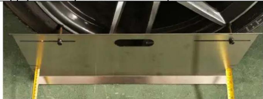
Step 2: Extend tape measures
Run the tape measures underneath the car as shown, 80 inches should be enough.
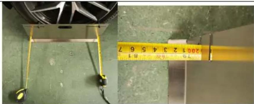
Step 3: Adjust stand-offs
Use the same procedure as shown in step to fit the other toe plate on the opposite of the vehicle and place the tape measure into the tape holder slots.
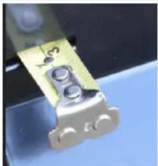
Caution: Check that the stand-offs on both plates are properly seated against the rim of the wheel.
Step 4: Measure Toe Unlock the tape measures and slide them into the slots. Do NOT re-lock the tape measures.
Leaving them unlocked will apply the prop. amount of tension. Pull on them slightly ar note the measurements.
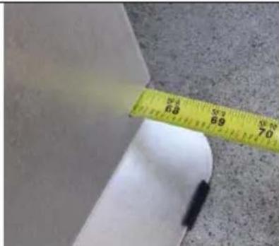
The rear tape measurement (side tow the rear of the vehicle) minus the front tape measurement(side closest to the front of the vehicle) is the total toe of axle. A larger measurement on the fro side indicates toe out, and a larger measurement on the rear side indicate toe in.
For example, if the front measurement is 66" and the rear measurement D2 is 3/32 the axle has a total toe in of 3/3
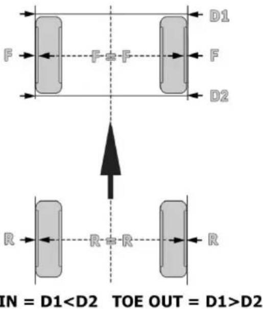
| TOE PLATE DEGREES TO INCH CONVERSION CHART Example: If the vehicle specs specify 0.4 degrees the toe should way between 1/8”and 3/16” measured by the toe plates. | |||||||
| Degrees Specification | 0 | 0.16 | 0.32 | 0.48 | 0.64 | 0.8 | 0.96 |
| Equivalent | 0 | 1/16” | 1/8” | 3/16” | 1/4” | 5/16” | 3/8” |
Note: When using alignment specs, note that the toe plates measure the TOTAL toe, not the toe of each wheel. Thus if your specs are given for wheel you will need to add those values together.
For example, if the toe in of each wheel is suppose to be 0.15 degrees, then the total toe should be 0.15 + 0.15 = 0.3 degrees.
The optional alignment specs gives total toe so these specs do not need modification, however you should use the degree specifications, NOT the inch specifications.
Tip: if the toe is correct but the steering wheel is crooked, turn the tire one side in, and the tie rod on the other side out an equal number of this will keep the toe measurement but adjust the position of the steering wheel. Make sure to adjust it the right direction!
Address: Shuangchenglu 803nong11hao1602A-1609shi, baoshanqu, shanghai 200000 CN.
Imported to AUS: SIHAO PTY LTD. 1 ROKEVA STREETEASTWOOD NSW 212 Australia
Imported to USA: Sanven Technology Ltd. Suite 250, 9166 Anaheim Place, Rancho Cucamonga, CA 91730
VEVOR
TOUGH TOOLS, HALF PRICE
Technical Support and E-Warranty Certificate www.vevor.com/support
VEVOR
TOUGH TOOLS, HALF PRICE
Assistance technique et certificat de garantie electronique www.vevor.com/support
SYSTEME D'ALIGNEMENT DES ROUES
MODELE:WBS-010
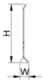
CARACTERISTIQUES DU PRODUIT:
| Modèle | L (mm) | H (mm) | DANS (mm) |
| WBS-010 | 580 | 211 | 35 |

LE FORFAIT COMPREND
www.vevor.com/support
VEVOR®
TOUGH TOOLS, HALF PRICE
Importato in AUS: SIHAO PTY LTD. 1 ROKEVA STREETEASTWOOD NSW 2122 Australia
Importato negli USA: Sanven Technology Ltd. Suite 250, 9166 Anaheim Place, Rancho Cucamonga, CA 91730
VEVOR
TOUGH TOOLS, HALF PRICE
HULP NODIG? NEEM CONTACT MET ONS OP!
PRODUCTSPECIFICATIONS:
| Model | Ik (mm) | H (mm) | IN (mm) |
| WBS-010 | 580 | 211 | 35 |

PAKKET INBEGREPEN
garantiecertificaat www.vevor.com/support