WZ-A301 - Pressure gauge Vevor - Free user manual and instructions
Find the device manual for free WZ-A301 Vevor in PDF.

| Product Type | Refrigeration Manifold Gauge |
| Brand | Vevor |
| Model | WZ-A301 |
| Low Side Measurement Range | -30 to 350 psi |
| High Side Measurement Range | 0 to 500 psi |
| Compatible Refrigerants | R134A, R22, R12, R502 |
| Product Dimensions | 285 x 250 x 90 mm |
| Product Weight | 2.1 kg (all accessories included) |
| Power Supply | Mechanical gauge, no battery |
| Main Functions | Pressure measurement, refrigerant charge, purge, zeroing |
| Safety Precautions | Wear goggles and gloves; do not exceed 80% of range |
| Maintenance | Recalibration possible: adjust needle to zero with a screwdriver |
| Cleaning | Wipe with a soft dry cloth |
| Spare Parts | Contact Vevor support for replacement parts |
| Technical Support | www.vevor.com/support |
| Certification | California Proposition 65 |
| Intended Use | For trained refrigeration and air conditioning technicians |
Frequently Asked Questions - WZ-A301 Vevor
User questions about WZ-A301 Vevor
0 question about this device. Answer the ones you know or ask your own.
Ask a new question about this device
Download the instructions for your Pressure gauge in PDF format for free! Find your manual WZ-A301 - Vevor and take your electronic device back in hand. On this page are published all the documents necessary for the use of your device. WZ-A301 by Vevor.
USER MANUAL WZ-A301 Vevor
Technical Support and E-Warranty Certificate www.vevor.com/support
MANIFOLD GAUGE SET OPERATING MANUAL
MODEL: WZ-A301
We continue to be committed to provide you tools with competitive "Save Half", "Half Price" or any other similar expressions used by represents an estimate of savings you might benefit from buying cert with us compared to the major top brands and doses not necessarily cover all categories of tools offered by us. You are kindly reminded carefully when you are placing an order with us if you are actually in comparison with the top major brands.
VEVOR®
MANIFOLD GAUGE SET OPERATING MANUAL
Model: WZ-A301
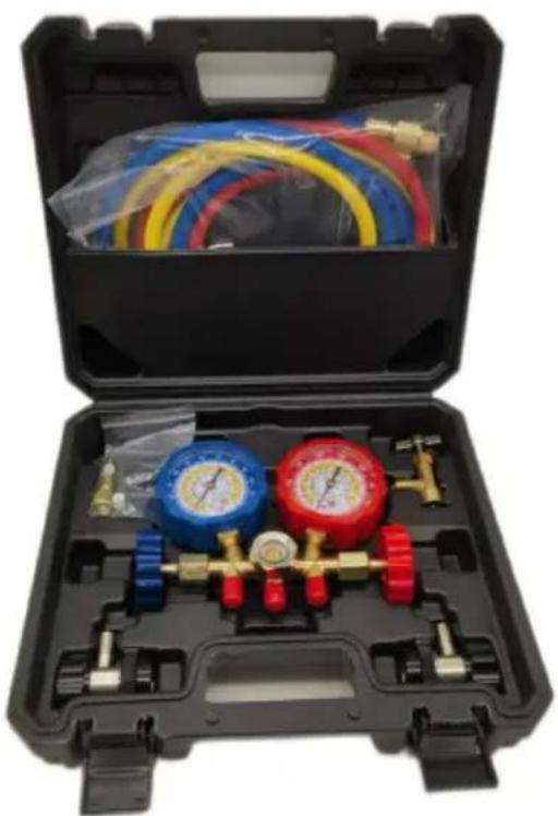
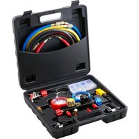
natural_image
Open black medical or gas cylinder kit with blue, red, and yellow tubing, no visible text or symbolsNEED HELP? CONTACT US!
Have product questions? Need technical support? Please feel free to contact us:

CustomerService@vevor.com
This is the original instruction, please read all manual instructions carefully before operating. VEVOR reserves clear interpretation of our user manual. The appearance of the product shall be subject to the product you received. Please forgive us that we won't inform you and there are any technology or software updates on our product.
Technical parameters
| Brand | Vevor |
| Model | WZ-A301 |
| Measuring range: | -30~350psi (Low Side Gauge; 0~500psi (High Side Gauge) |
| Refrigerants | R134A/ R22/ R12/R502 |
| Product size (mm) | 285×250×90 |
| Product weight (kg) | 2.1 (Including all accessories) |
Safety Precautions
Safety & Warning
Warning:
- Not exceed 80% of claimed range of manifolds when using.
- Un-proper operation may lead to leakage or personal injury.
- Please read manual & operation instruction of manifold or equipment
- The refrigeration gauge has been calibrated at the factory; however, due to handling and shipping it may be lightly out of adjustment. To a unscrew and firmly hold center screw fixed with screwdriver and with thumb and forefinger gripping pointer near center, gently turn pointer to zero. Repeat carefully if not on zero.
IMPORTANT:
- Gauges are available for most refrigerants in°F.
- Please read before putting new equipment into operation. The Compound Rubber forms seals around the valve stem. Tighten the valve nut a quater to half turn to take up the set before commencing open and retighten as necessary to keep the seal tight.
NOTE: Check equipment manufactures catalogue or instruction sheets for specific recommendations on refrigerant charge, oil change and service procedures for any particular piece of equipment.
WARNING! To prevent personal injury.
Wear goggles when working with refrigerants. Contact with refrigerants may cause injury.
Wear gloves when working with refrigerants. Contact with refrigerants may cause injury.
Incorrect use or connections may cause leaks or explosions. Read and follow the instructions carefully and take precautions avoid leaks or explosions. Confirm that all associated devices grounded correctly before use.
CALIFORNIA PROPOSITION65 This product contains chemicals known to the State of California to cause cancer and birth de or other reproductive harm.
This manifold is designed for use by technically trained refrigeration and air conditioning service technicians. Due to the unusually HIGH PRESSURE AND HAZARDOUS GASES IN ALLSTSTEM is, misapplication could result in injury or death. Manufactory warns against the sale to or use of this product any other than professionally trained personnel.
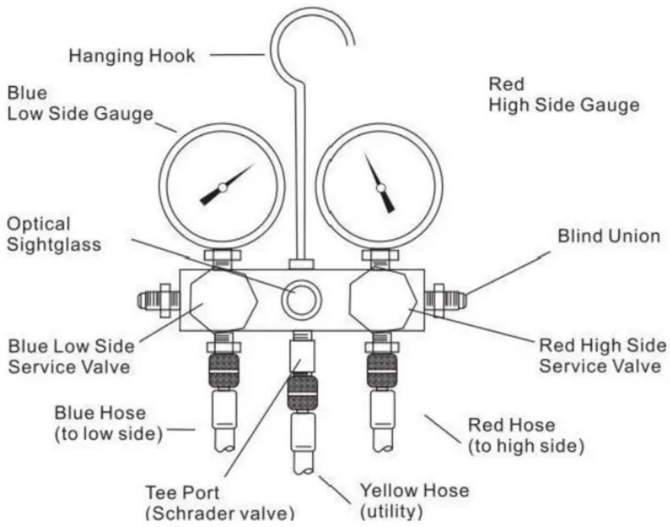
Product Structure Diagram
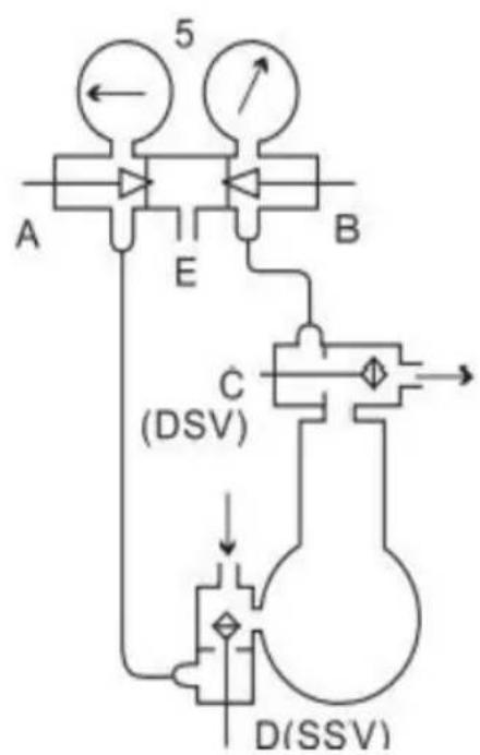
Instruction of use
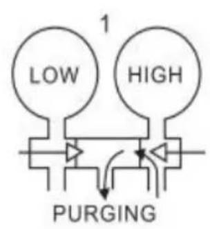
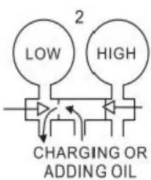
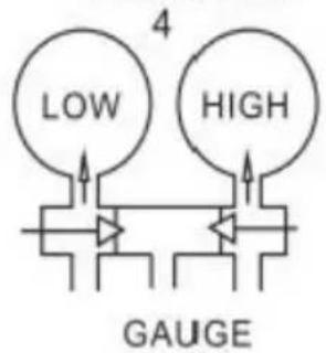
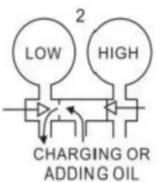
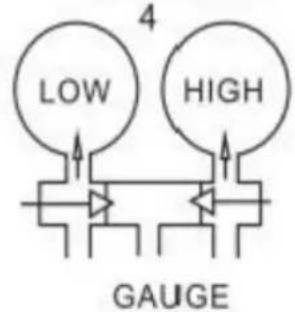
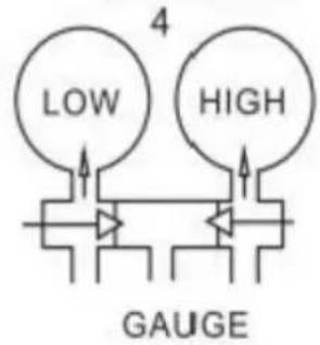
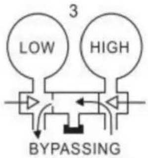
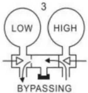
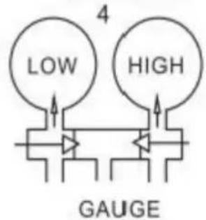
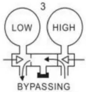
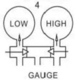
Schematic of gauge manifold installation on external drive compressor with service valves. A-Manifold Suction Valve. B-Manifold Discharge Valve C-Compressor Discharge Service Valve (DSV). D-Compressor Suction Service Valve(SSV). E-Servide Opening. 1-Purging. 2-Charging or Adding Oil. 3-Bypassing. 4-Gauge Reading. 5-Both manifold valves are turned the way in. System is pumping vapor and both low and high-side pre are being read.
VALVE MUST BE CLOSED
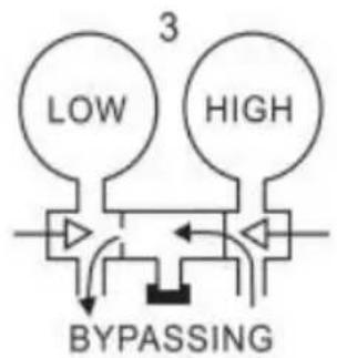
flowchart
graph TD
    A["Low"] --> B["Switch"]
    C["High"] --> D["Switch"]
    B --> E["Inverter"]
    D --> F["Inverter"]
    E --> G["BYPASSING"]
    F --> G
    style A fill:#f9f,stroke:#333
    style C fill:#f9f,stroke:#333
    style D fill:#f9f,stroke:#333
    style G fill:#ccf,stroke:#333
Lines from the manifold are attached to the SSV at D and should b one to two turns lose while the line to the DSV should be tightened open both of the manifold valves at A and B 1/4 turn to 1/2 turn a the middle opening,E.
Now turn the(DSV)Cstemin1'8 to 1/4 turn for just a moment(crack the valve).A surge of high-pressure refrigerant will then rush through the li and the manifold and purge to the atmosphere at the loose connectic D the SSv. This connection may then be tightened.Purging is necessary to remove air and moisture from the manifold and lines. NOTE: Purgi must be held to a minimum to avoid damage to the atmosphere.
Carefully test for leaks while the manifold and its lines are under hig pressure. Correct any leak immediately.
Various service and testing operations may be performed after the testing manifold has been installed:
- Observe operating pressures by:
Closing valve A by turning all the way in.
Closing valve B by turning all the way in.
Cracking open back seat of valve C.
Cracking open back seat of valve D.
- Charge refrigerant into system by:
Connecting refrigerant cylinder to E (vapor only).
Opening valve A.
Closing valve B.
Closing front seat of valve D slowly.
- Purge condenser by:
Closing valve A.
Closing valve B.
Cracking open valve C.
- Charge liquid refrigerant into high side by:
Connecting refrigerant cylinder to E.
Closing valve A.
Opening valve B.
Mid-positioning valve C.
- Build up pressure in low side for control setting or to test for leaks
Sealing E with seal cap.
Opening valve A.
Close valve C.
PRESSURE AND COMPOUND GAUGE RECALIBRATION INSTRUCTIONS:
The refrigeration gauge has been calibrated at the factory; however, due to handling and shipping, it may be slightly out of adjustment. To adjust, unscrew the lens and firmly hold the center screw fixed with a screwdriver, and with thumb and forefinger gripping the pointer near the center, gently turn the pointer to zero. Repeat carefully if not on zero. It's unavailable for wet gauge, and the wet gauge does not require gauge zeroing.
Scope of application
For R134A/ R22/ R12/R502 Refrigerant only
Common fault analysis
| fault phenomenon | failure cause | solution |
| Refrigeration agent leakage | The conversion joint ga is too large | Tighten the switch connector |
VEVOR®
TOUGH TOOLS, HALF PRICE
Technical Support and E-Warranty Certificate
www.vevor.com/support
Made In China
VEVOR®
TOUGH TOOLS, HALF PRICE
natural_image
Open black medical or gas testing kit with blue and red pressure gauges and tubing (no visible text or labels)BESOIN D'AIDE? CONTACTEZ-NOUS!
Mode d'emploi
flowchart
graph TD
    A["LOW"] --> C["PURGING"]
    B["HIGH"] --> C["PURGING"]
    style A fill:#fff,stroke:#000
    style B fill:#fff,stroke:#000
    style C fill:#fff,stroke:#000
VALVE MUST BE CLOSED


www.vevor.com/support
Fabriqué en Chine
VEVOR®
TOUGH TOOLS, HALF PRICE
natural_image
Open black medical or gas testing kit with blue and red pressure gauges and tubing (no visible text or labels)Kundenservice@vevor.com
Gebrauchsanweisung
VALVE MUST BE CLOSED

natural_image
Open black medical or gas testing kit with blue, red, and yellow pressure gauges and tubing (no visible text or labels)VALVE MUST BE CLOSED

natural_image
Open black medical or gas testing kit with blue and red pressure gauges and tubing (no visible text or labels)flowchart
graph TD
    A["LOW"] --> C["PURGING"]
    B["HIGH"] --> C["PURGING"]
    style A fill:#fff,stroke:#000
    style B fill:#fff,stroke:#000
    style C fill:#fff,stroke:#000

VALVE MUST BE CLOSED

natural_image
Open black medical or gas testing kit with blue, red, and yellow pressure gauges and tubing (no visible text or labels)POTRZEBUJESZ POMOCY? SKONTAKTUJ SIĘ Z NAMI!
VALVE MUST BE CLOSED
www.vevor.com/support
natural_image
Open black medical or gas testing kit with blue and red pressure gauges and tubing (no visible text or labels)HULP NODIG? NEEM CONTACT MET ONS OP!
Klantenservice@vevor.com
Gebruiksaanwijzing
flowchart
graph TD
    A["LOW"] --> C["PURGING"]
    B["HIGH"] --> C["PURGING"]
    style A fill:#fff,stroke:#000
    style B fill:#fff,stroke:#000
    style C fill:#fff,stroke:#000

VALVE MUST BE CLOSED

www.vevor.com/support
Gemaakt in China
VEVOR®
TOUGH TOOLS, HALF PRICE
natural_image
Open black medical or gas testing kit with blue and red pressure gauges and tubing (no visible text or labels)BEHÖVER HJÄLP? KONTAKTA OSS!
VALVE MUST BE CLOSED

www.vevor.com/support
Tillverkad i Kina