XC4027A - Spring compressor Vevor - Free user manual and instructions
Find the device manual for free XC4027A Vevor in PDF.

User questions about XC4027A Vevor
0 question about this device. Answer the ones you know or ask your own.
Ask a new question about this device
Download the instructions for your Spring compressor in PDF format for free! Find your manual XC4027A - Vevor and take your electronic device back in hand. On this page are published all the documents necessary for the use of your device. XC4027A by Vevor.
USER MANUAL XC4027A Vevor
Technical Support and E-Warranty Certificate www.vevor.com/support
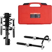
STRUT SPRING COMPRESSOR
MODEL:XC4027A
We continue to be committed to provide you tools with competitive price. "Save Half", "Half Price" or any other similar expressions used by us only represent estimate of savings you might benefit from buying certain tools with us compared top brands and doses not necessarily mean to cover all categories of tools offered are kindly reminded to verify carefully when you are placing an order with us actually saving half in comparison with the top major brands.
VEVOR®
TOUGH TOOLS, HALF PRICE
STRUT SPRING COMPRESSOR
MODEL:XC4027A
natural_image
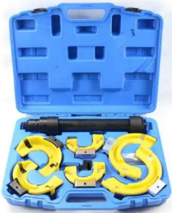
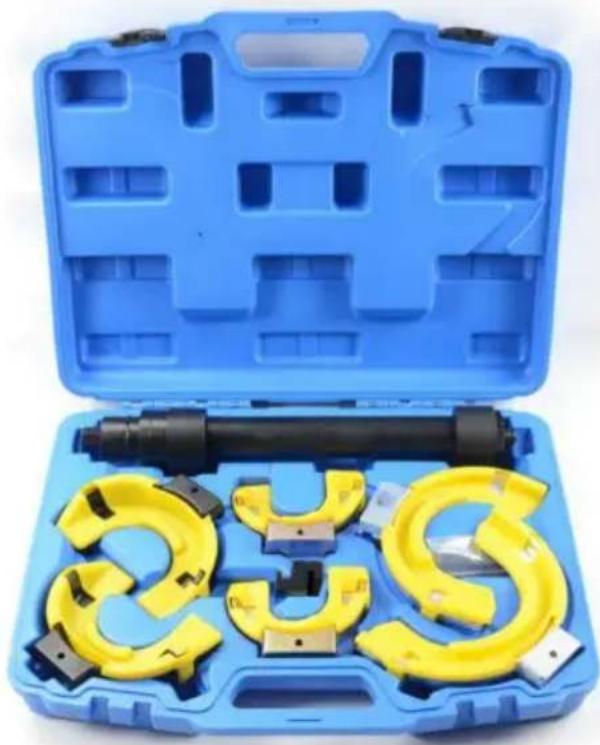
Blue plastic toolbox containing a yellow and black mechanical clamp kit (no text or symbols visible)NEED HELP? CONTACT US!
Have product questions? Need technical support? Please feel fr contact us:

CustomerService@vevor.com
This is the original instruction, please read all manual instruction carefully before operating. VEVOR reserves a clear interpretation user manual. The appearance of the product shall be subject to product you received. Please forgive us that we won't inform you there are any technology or software updates on our product.
IMPORTANT SAFEGUARDS
 | Danger! Read the operating instructions to reduce the inquiry. |
 | WARNING! This symbol, placed before a safety comment indicates a kind of precaution, warning, or danger. Ignore warning may lead to an accident. |
 | Caution! Wear safety goggles. Sparks generated during working or splinters, chips, and dust emitted by the device cause loss of sight. |
 | Caution! Wear gloves. When using this product, please gloves for security. |
General safety information
Please read and store these instructions carefully before commissioning the device is shared with the user, pass it on.
The manufacturer is not liable for personal injury/property damage cause by use or incorrect operation.
WARNING: Please observe to avoid malfunctions, damage, and health impairment, the following information:
- Danger! Stop squeezing the spring before winding the coil to touch other. Be extra careful when using an aerial impact screwdriver use
- Ensure that health and safety regulations, regulations of the local authorities, and general workshop practice in the use of this equipn
- Wear tested goggles. Standard glasses are not enough!
- Do not squeeze the spring so far that the jaws touch.
- Do not operate spring tensioners if parts are damaged or missing, this may cause Failure and / or personal injury.
- Non-qualified persons must not use the spring tensioner.
-
Be aware of the applications, restrictions, and potential hazards of the spring tensioner.
-
Keep the spring tensioner in good condition. Replace or repair damage parts.
- When the tool receives a large tensile force, it is not possible to use external machinery, such as an air gun or an electric wrench, to the screw. At this time, it is necessary to use a manual socket with compress the spring on both sides.
Use only original parts. Non-approved parts may be dangerous and will void the warranty.
- Keep the work area clean, tidy and ensure adequate lighting.
- Make sure the floor is not slippery and wear non-slip shoes.
- Remove inappropriate clothing, ties, watches, rings, and other loose.
- Remove jewelry. Tie back long hair.
- Wear suitable protective clothing.
- When not in use, clean the spring tensioner, keep it safe, dry, an in a child-safe place.
SAVE THESE INSTRUCTIONS
Product Parameters
| Max.Load 4500 kg |
Jaw Parameters
| Colour Specifications Compression Range | ||
| Gold Jaw | 65 -125mm | 75-320mm |
| Black Jaw | 86 -160mm | 85-325mm |
| Silver Jaw | 125.5-212mm | 65-300mm |
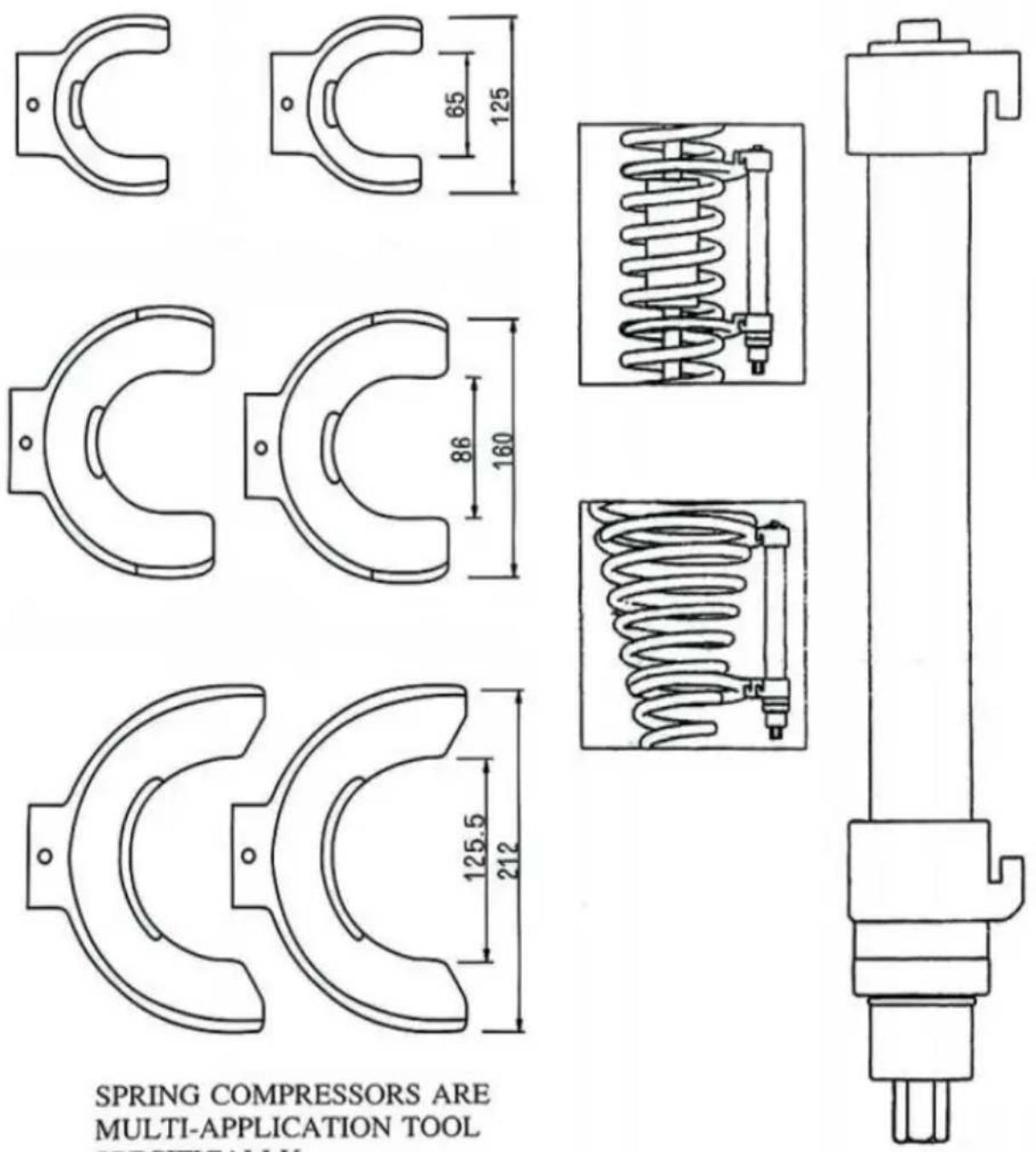
SPRING COMPRESSORS ARE MULTI-APPLICATION TOOL SPECIFICALLY.
DEVELOPED FOR MODERN MACPHERSON SUSPENSIONS · USING A RANGE OF 3SETS OF INTERCHANGEABLE MONO BLOCK FORKS


| No. | Name | Qty. |
| 1 | Tool Box | 1 |
| 2 | Central Axis | 1 |
| 3 | Black Jaw | 2 |
| 4 | Gold Jaw | 2 |
| 5 | Silver Jaw | 2 |
| 6 | Extension Block | 1 |
| 7 | Screw | 6 |
| 8 | Hex Wrench | 1 |
natural_image
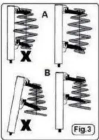
Mechanical spring assembly diagrams labeled A and B, showing spring supports and a central X component (no text or symbols beyond labels)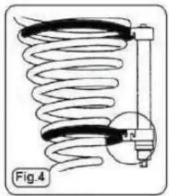
natural_image
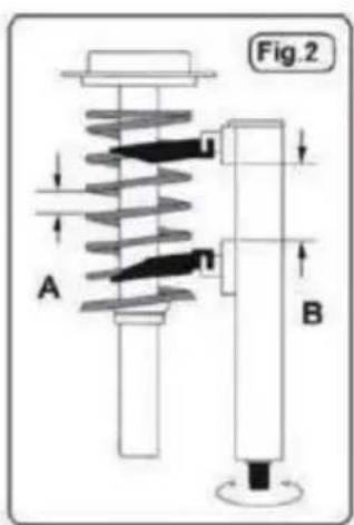
Diagram of a coiled spring connected to a vertical tube, labeled Fig.4 (no text or symbols on the diagram itself)- Suitable for McPherson spring struts.
- Equipped with a yoke extension bracket, which also allows use on conical springs.
- Comes with three pairs of interchangeable yokes of different sizes for variety of vehicle applications and with plastic yoke protection.
- These protect the spring sheath from damage that can invalidate the warranty of the vehicle manufacturer.
- The safety bars are carefully shaped to prevent deflection of the sp under pressure.
- The spindle is driven by a 22-mm hexagonal nut.
- Each jaw has safety lips to prevent slipping and is designed to ad the inclination of the spring.
- This ensures maximum surface contact between the clamping jaws a spring, eliminating the risk of slipping the clamp around the sp
Operation
- This product is a mechanical thread tool. Before use, please apply lubricating grease on the thread, which can greatly extend the serv life of the product.
- Warning! Please do not strain the spring so much that the coil coil the clamping jaws touch.
-
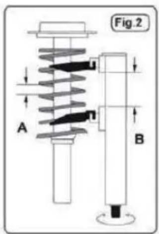
Make sure that the clamping jaws and the body of the tensioner a aligned correctly at all times during the compression of the spring have a good distance from each other.
-
For conical springs, the center of the spring should be parallel to the body of the Spring tensioner.
- If necessary, use the extension block to keep the spring and the b the tensioner parallel.
- Secure the strut with a clamp, vice, or other suitable holding device
For compressing a strut removed from a vehicle
- Mount the selected jaws on the body of the spring tensioner, atta retaining screws, and tighten them tightly.
- Using air tools or hand tools, drive the hexagon nut apart to the spring. The jaws must be compressed as much as possible to compression of as many turns as possible.
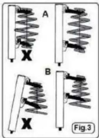
- Place the spring tensioner on the spring, making sure that the spin seats are correct and sit between the safety lips and the outer rib cannot slip out when compressed.
- Make sure the jaws and body are aligned correctly.
For decompressing a strut removed from a vehicle
- Reverse the compression process to decompress the spring
General maintenance
- Check the spring tensioner before each use to ensure that it is damaged or worn out. Do not use the device in case of suspicion, I contact your local dealer, who can advise you on repair kits and spa parts.
- Lubricate the spring tensioner spindle as required, at least every 6 months.
- Keep the spring tensioner clean and keep it in a safe, dry, cold-insulated place when not in use.
- Keep out of the reach of children.
Made In China
VEVOR®
TOUGH TOOLS, HALF PRICE
Technical Support and E-Warranty Certificate www.vevor.com/support
VEVOR®
TOUGH TOOLS, HALF PRICE
natural_image
Blue plastic toolbox containing yellow industrial tools and a cylindrical device (no visible text or symbols)BESOIN D'AIDE? CONTACTEZ-NOUS!

natural_image
Mechanical spring assembly diagrams labeled A and B, showing spring components with no text or symbols
natural_image
Diagram of a coiled spring assembly with a vertical rod and base, labeled Fig.4 (no text or symbols on the diagram itself)Federbein KOMPRESSOR
MODELL:XC4027A
natural_image
Blue plastic toolbox containing a yellow and black mechanical clamp kit (no text or symbols visible)Kundenservice@vevor.com

natural_image
Mechanical spring assembly diagrams labeled A and B, showing spring components with no text or symbols
natural_image
Diagram of a coiled spring connected to a vertical rod, labeled Fig.4 (no text or symbols on the diagram itself)natural_image
Blue plastic toolbox containing a yellow and black mechanical clamp kit (no text or symbols visible)
natural_image
Mechanical spring assembly diagrams labeled A and B, showing spring components with no text or symbols
natural_image
Diagram of a coiled spring connected to a vertical rod, labeled Fig.4 (no text or symbols on the diagram itself)natural_image
Blue plastic toolbox containing yellow industrial clamps and a cylindrical tool, no visible text or symbols
natural_image
Mechanical spring assembly diagrams labeled A and B, showing spring components with no text or symbols
natural_image
Diagram of a coiled spring assembly with a vertical rod and base, labeled Fig.4 (no text or symbols on the diagram itself)natural_image
Blue plastic toolbox containing yellow industrial clamps and a cylindrical tool, no visible text or symbolsPOTRZEBUJESZ POMOCY? SKONTAKTUJ SIĘ Z NAMI!

natural_image
Mechanical spring assembly diagrams labeled A and B, showing spring components with no text or symbols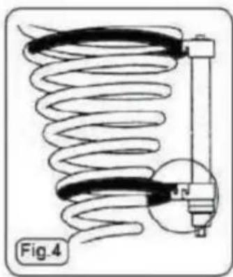
natural_image
Diagram of a coiled spring assembly with a vertical rod and base, labeled Fig.4 (no text or symbols on the diagram itself)STRUT VEERCOMPRESSOR
MODEL:XC4027A
natural_image
Blue plastic toolbox containing yellow industrial clamps and a cylindrical tool, no visible text or symbolsHULP NODIG? NEEM CONTACT MET ONS OP!
Klantenservice@vevor.com
| Nee. Naam | Aantal | |
| 1 | Gereedschapskist | 1 |
| 2 | Centrale as | 1 |
| 3 | Zwarte Kaak | 2 |
| 4 | Gouden kaak | 2 |
| 5 | Zilveren Kaak | 2 |
| 6 | Verlengblok | 1 |
| 7 | Schroef | 6 |
| 8 | Inbussleutel | 1 |
natural_image
Mechanical spring assembly diagrams labeled A and B, showing spring components with no text or symbols
natural_image
Diagram of a coiled spring connected to a vertical rod, labeled Fig.4 (no text or symbols on the diagram itself)natural_image
Blue plastic toolbox containing yellow industrial clamps and a cylindrical tool, no visible text or symbolsBEHÖVER HJÄLP? KONTAKTA OSS!

natural_image
Four-panel diagram showing spring-mass systems labeled A, B, and X, with no readable text or symbols.