TS815 - Pets Vevor - Free user manual and instructions
Find the device manual for free TS815 Vevor in PDF.

| Product Type | Pet Bike Trailer |
| Brand | Vevor |
| Model | TS815 |
| Use | Transport of dogs or other pets (max 45 kg) |
| Maximum Load Capacity | 100 lb (45 kg) |
| Interior Dimensions (L x W x H) | 31.9 x 22 x 24.4 inches (81 x 56 x 62 cm) |
| Trailer Weight (approx.) | Approx. 13 kg |
| Frame Material | Steel |
| Cover Material | 600D Oxford Fabric |
| Color | Black and Blue |
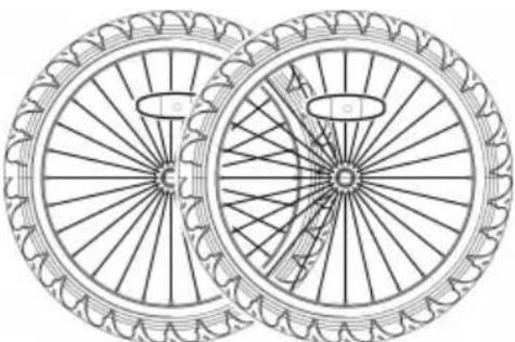
| Rear Wheels | Steel, 16 x 1.75 inches |
| Front Wheel (stroller kit) | Plastic, 8 inches |
| Parking Brakes | Yes, integrated into wheel guards |
| Hitch | Universal, compatible with nut and quick-release axles |
| Safety Flag | Included |
| Reflectors | Front white, rear red (4 pieces) |
| Stroller Conversion | Yes, kit included |
| Storage Temperature | -10°F to 150°F (-23°C to 65°C) |
| Fabric Care | Hand wash with warm water and mild soap (no bleach) |
| Hitch Weight Distribution | Between 6.6 lb and 17.6 lb (3 to 8 kg) |
| Minimum Rider Age | 16 years |
Frequently Asked Questions - TS815 Vevor
User questions about TS815 Vevor
0 question about this device. Answer the ones you know or ask your own.
Ask a new question about this device
Download the instructions for your Pets in PDF format for free! Find your manual TS815 - Vevor and take your electronic device back in hand. On this page are published all the documents necessary for the use of your device. TS815 by Vevor.
USER MANUAL TS815 Vevor
Technical Support and E-Warranty Certificate
www.vevor.com/support
PET BIKE TRAILER
MODEL: TS815
We continue to be committed to provide you tools with competitive price. "Save Half", "Half Price" or any other similar expressions used by us only represent estimate of savings you might benefit from buying certain tools with us compared top brands and does not necessarily mean to cover all categories of tools offered are kindly reminded to verify carefully when you are placing an order with us actually saving half in comparison with the top major brands.
MODEL: TS815

natural_image
Line drawing of a mobile cleaning or cleaning tool with wheels and handle (no text or symbols)Important: Keep these instructions for future reference
NEED HELP? CONTACT US!
Have product questions? Need technical support? Please feel fr contact us:
Technical Support and E-Warranty Certificate www.vevor.com/support
This is the original instruction, please read all manual instruction carefully before operating. VEVOR reserves a clear interpretation user manual. The appearance of the product shall be subject to product you received. Please forgive us that we won't inform you there are any technology or software updates on our product.
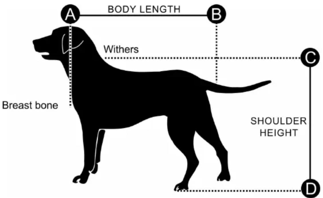
CHOOSE THE RIGHT SIZE OF TRAILER
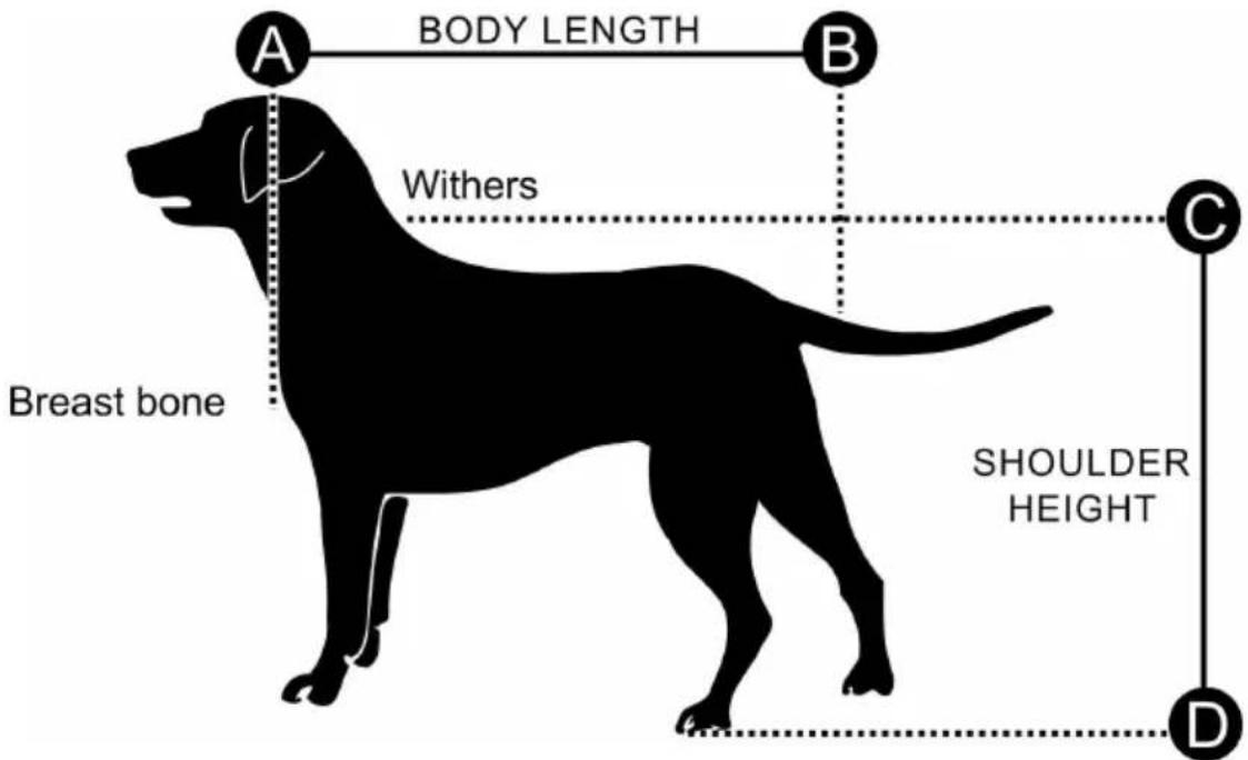
| Trailer Size | X-Large |
| Max. Body Length | 35 in. (90 cm) |
| Max. Shoulder Height | 24 in. (61 cm) |
| Max. Weight | 100 lbs. (45 kg) |
SAFETY INSTRUCTIONS
WARNING
Do read instructions before driving. Failure to comply with the instructions and warnings in this manual could result in serious injury or death.
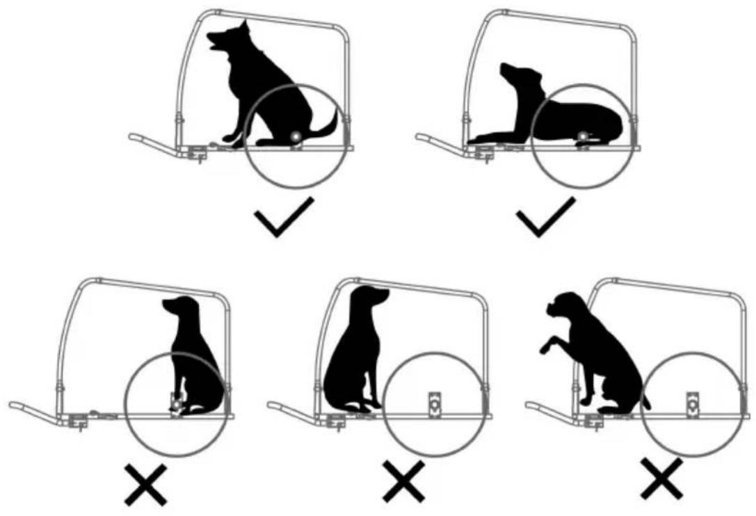
- Consult a veterinarian to ensure it is safe for your pet to ride in
● Make sure pet cannot make contact with the wheel spokes. - Check comfort and safety of pet frequently, especially during hot or cold weather.
-
Never leave pet unattended and ALWAYS HOLD THE TRAILER/STROLLER FROM TIPPING BACKWARD WHEN DOG IS ENTERING OR LEAVING THE TRAILER.
● DO NOT use with a total load that exceeds 100 lbs. (45kg).
● Never use pet trailer for transporting child or cargo. -
DO NOT make any modifications to the product. Any parcels place the trailer may cause the trailer to become unstable.
- DO NOT over-inflate the tires. Failure to comply with the rated pre on the tire sidewall may lead to explosion of the tire and possible
- Before each ride, be sure the trailer does not interfere with braking pedaling or steering of the bicycle.
● Always comply with local regulations when using the trailer on publ roadways. - Never ride a bicycle at night without adequate lighting. Obey all legal requirements for lighting.
- When using your trailer, you are towing extra weight and a bigger vehicle. You must allow more time for braking, slowing, stopping a starting, and allow more room for turns and passageways. Experim with the loaded trailer in an uncongested area until you become f with how your bike handles towing a trailer.
- Avoid rocks, curbs, hard braking and sudden swerving. Avoid riding over obstacles with one wheel, as this may cause the trailer to ti
● Always ride with the front and rear doors fully closed to protect pe flying debris and prevent pet from jumping from the trailer
● The rider of the bicycle must be at least 16 years old. - Recommended speed limits: - 10 mph (16 km/h) on smooth, straight roads - 5 mph (8 km/h) when turning or on uneven roads.
- Trailer weight must be properly distributed for safe handling. The weight on the hitch connector should be between 30 N (≈6.6 lbs. kg) and 80 N (≈17.6 lbs. or 8 kg). To measure this, load your t place it next to bathroom scale. Step on scale and make a note weight. Standing on scale, lift up the end of the tow bar one foc (approximately 25cm) off the ground. If the weight is too low, the wheel of the bicycle could lose traction. If it is too high the hitch overloaded.
Never overload the trailer and never ride with a tow bar load that is the specified range of 6.6 to 17.6 lbs. (3 - 8 kg). Always distribute evenly. Failure to do so could result in accidents with serious injury death.
Tip: Make sure that your dog is positioned with its center of gravity as possible to the wheel axle. This is the best way to ride with an weight distribution.
MODEL AND PARAMETERS
| Model | TS815 |
| Type | Tow/Hand Push |
| Max. Load | 100lbs |
| Bin Size | 31.9*22*24.4inch |
| Wheels | Steel, 16*1.75inch (Rear)Plastic, 8inch(Front) |
| Material | Steel, 600D Oxford cloth |
| Color | Black & Blue |
CONTENTS
 |  |
| 1 x Main frame | 2 x Wheels |
 |  |
| 1 x Tow bar receiver | 1 x Universal hitch |
 |  |
| 1 x Tow bar | 2 x Wheel guard |
 |  |
| 2 x Handle bar holder | 1 x Flag |
 |  |
| 2 x Rear reflectors (red) | 2 x Front reflectors (white) |
| 1 x Handle bar | 1 x front wheel with quick-rele skewer |
 + +  + + |  |
| 1 x 11mm Wrench +Hex key+ x User Manual | |
How to Assemble
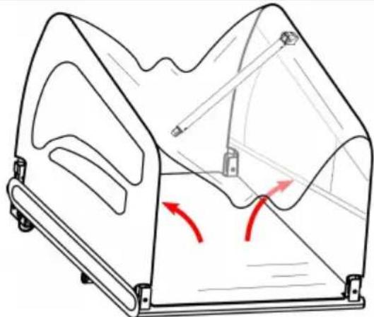
1. Opening the Main Frame
natural_image
Technical line drawing of a mechanical device with internal components and red motion arrows indicating movement (no text or symbols)Figure 1
Take out the trailer's main frar and all other components from the carton. Remove black protective caps on 4 corners. Raise both side panels to an upright position (Figure 1).
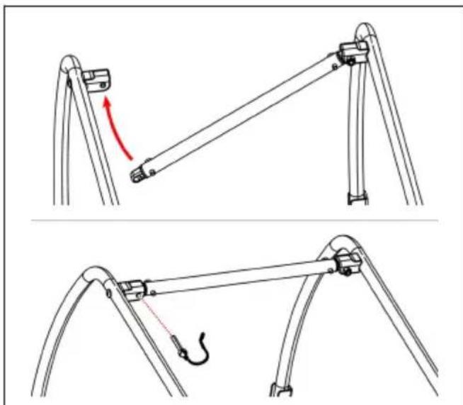
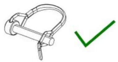
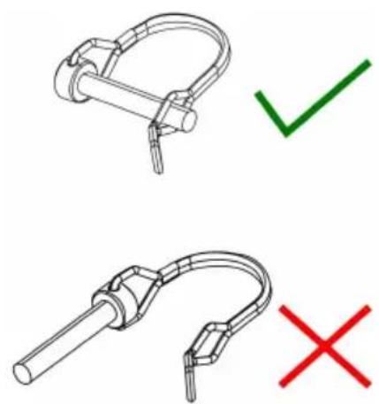
Fasten the crossbar to the top part of the main frame. Raise the cross bar using the safety pin attached to the bolt (Figure sure that safety pins are properly locked in place as shown
natural_image
Technical line drawing of a mechanical linkage assembly with a red arrow indicating motion direction (no text or symbols)Figure 2
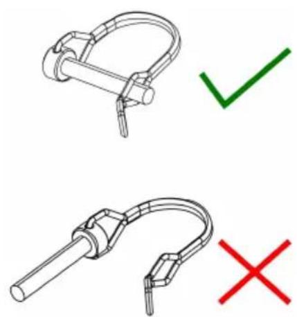
natural_image
Technical line drawing of two mechanical components with check and cross marks (no text or symbols)Figure 3
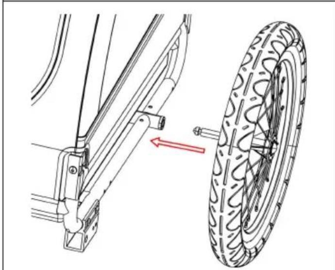
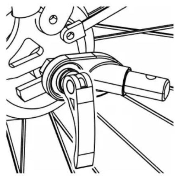
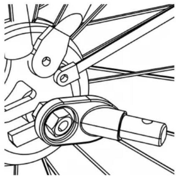
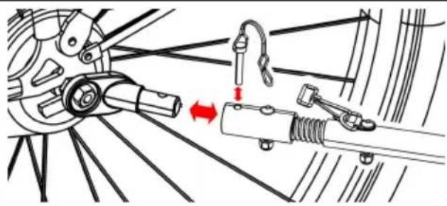
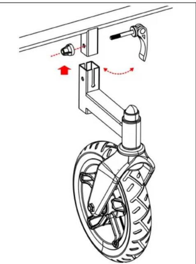
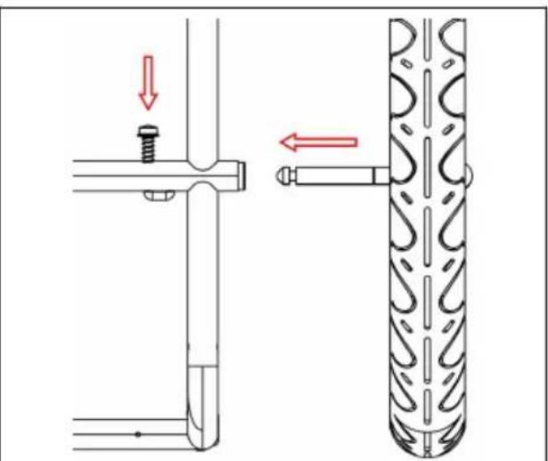
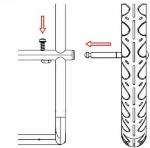
2. Attaching the Wheels
Insert wheel axle into axle receiver underneath the trailer frame until in place (Figure 4, Figure 5). Pull firmly on wheel to confirm the a engaged.
Repeat to attach the second wheel on other side.
To remove the wheel, press the L-shape hook under the trailer and
natural_image
Technical diagram showing a bicycle suspension system with a tire and mechanical components, no text or symbols present.Figure 4
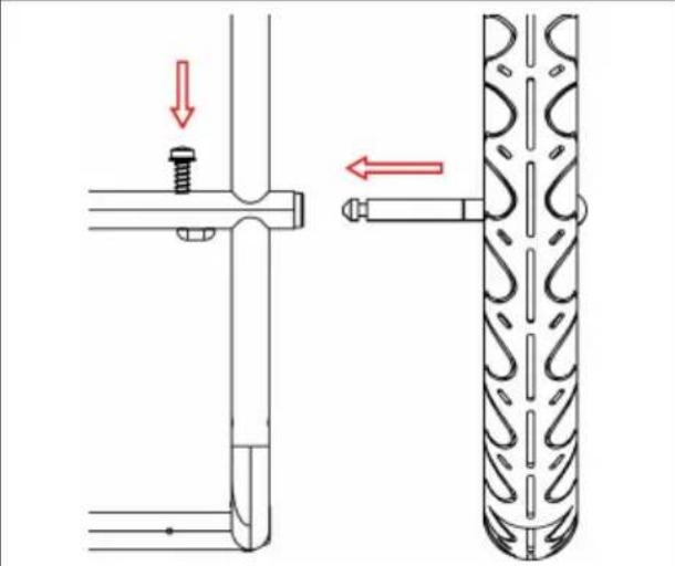
Figure 5
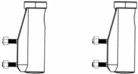
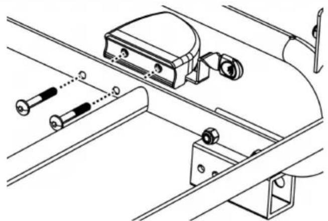
3. Installing the Parking Brakes/Wheel Guards
Insert wheel guard bolts through frame tube. Match holes in guards to bolts. Tighten securely with hex key (Figure 6). Rewheel guard on other side.
natural_image
Technical line drawing of a mechanical assembly with rollers, brackets, and a central housing (no text or symbols)Figure 6
Pull outward the handle on wheel guard to brake. Push back handle to release (Figure 7).
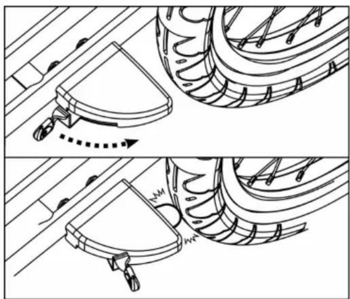
natural_image
Technical line drawing showing two mechanical assembly steps with no visible text or symbolsFigure 7
WARNING
Always engage the brakes when not riding/pushing.
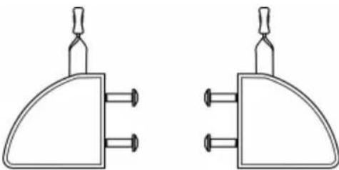
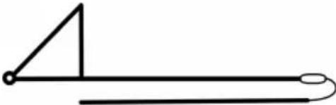
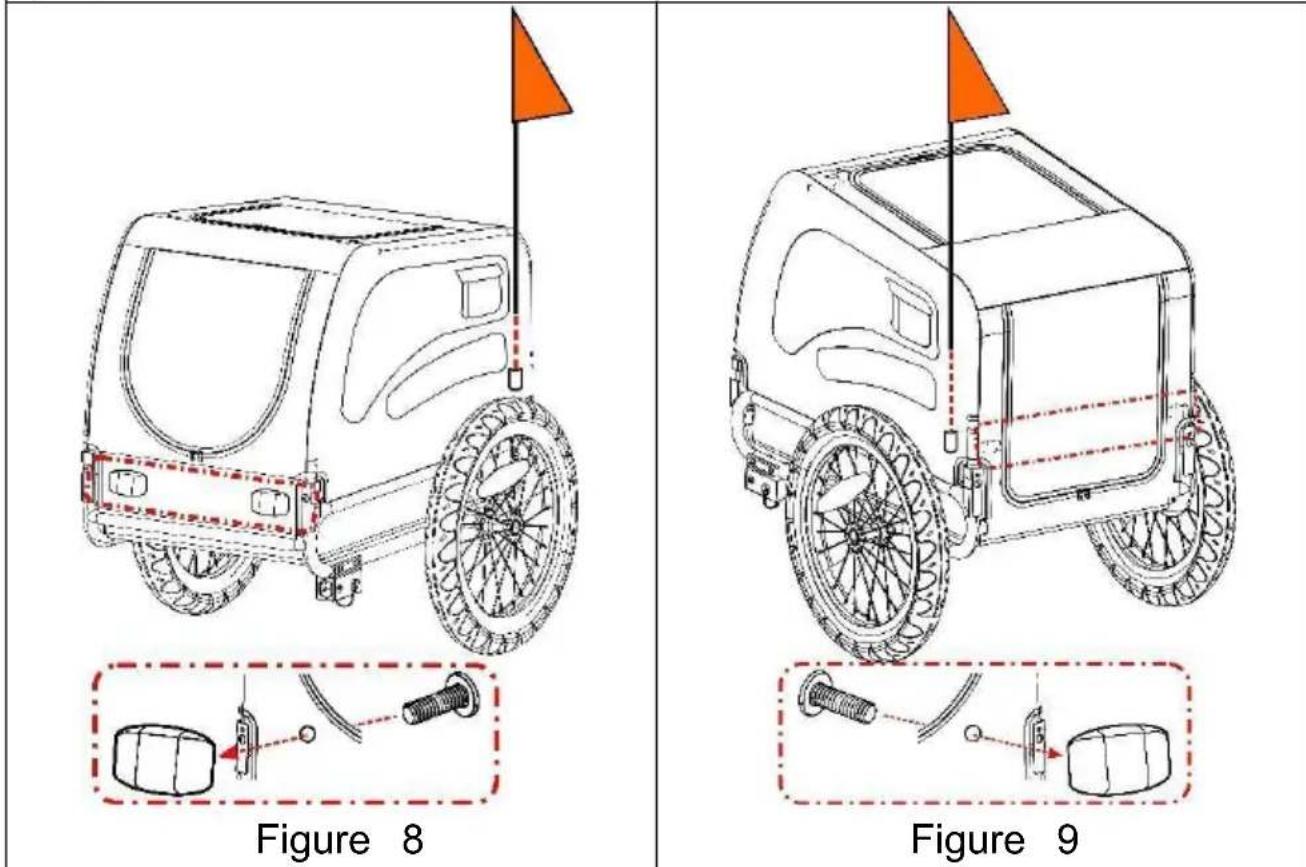
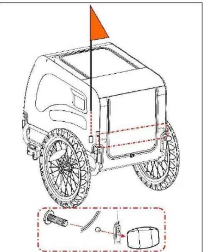
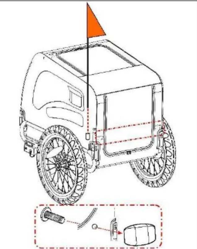
4. Attaching the Flag
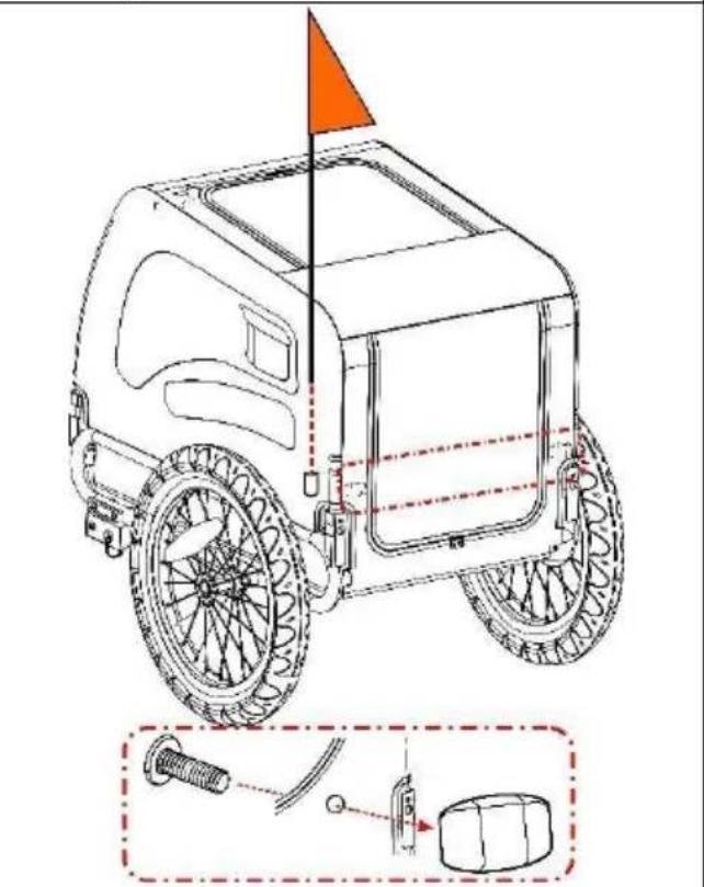
Insert the flag pole into the flagpole pocket at the left rear side panel (Figure 8, Figure 9).
Insert screws into holes on the cover to fasten front (white) (red) reflectors.
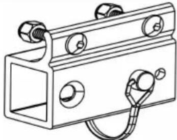
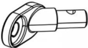
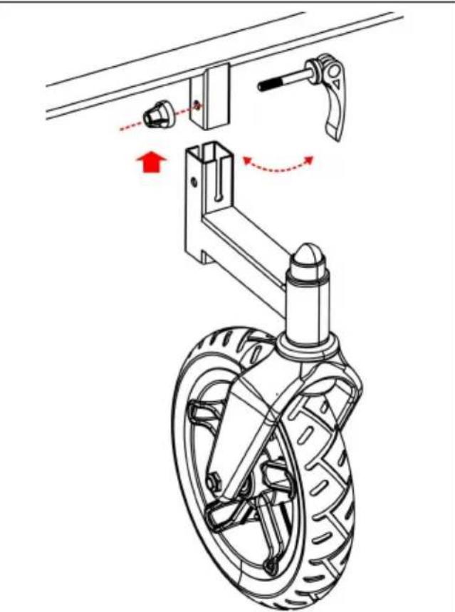
5. Installing the Tow Bar
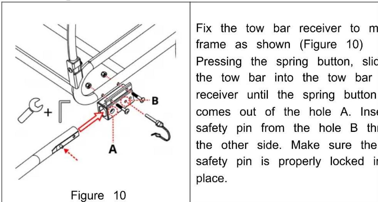
Fix the tow bar receiver to m frame as shown (Figure 10) Pressing the spring button, slid the tow bar into the tow bar receiver until the spring button comes out of the hole A. Inse safety pin from the hole B th the other side. Make sure the safety pin is properly locked in place.
6. Attaching Trailer to Bicycle
- Quick-release Axle: Remove the quick-release from the left bike's rear axle. Install the hitch between the quick-release and Tighten the quick-release following the bike manufacturer's man Hitch can remain on the bike when the trailer is removed (Fi
natural_image
Technical line drawing of a mechanical assembly with no visible text or symbolsFigure 11
WARNING
The tension-adjusting nut must engage the threads for at least five full turns in order to ensure adequate clamping force for holding the rear wheel securely. Failure to tighten the tension-adjusting nut fully may result in accidents with serious injury or death. If the quick-release skewer is too much it must be replaced. Consult a professional bicycle mechanic for the appropriate parts and assistance.
- Nutted Axle: Unscrew the nut with washer from the left s bike's rear axle. Install the hitch onto the axle and screw the on with the washer(Figure 12).
natural_image
Technical line drawing of a mechanical linkage assembly (no text or symbols)Figure 12
WARNING
The axle nut must engage the threads for at least five full tu in order to ensure adequate clamping force for holding the rear wheel securely. Failure to tighten the nut fully may result accidents with serious injury or death. If the axle is too short Universal Hitch cannot be used Consult a professional bicycle mechanic for the appropriate parts and assistance.
- Thru Axle: The universal hitch doesn't fit a bike with thru Please consult the retailer for possible solution.
natural_image
Mechanical assembly diagram showing a linkage mechanism with no visible text or symbols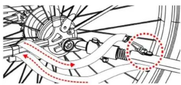
natural_image
Mechanical assembly diagram showing gear and shaft components with red dotted arrows indicating motion or flow (no text or labels)Figure 13
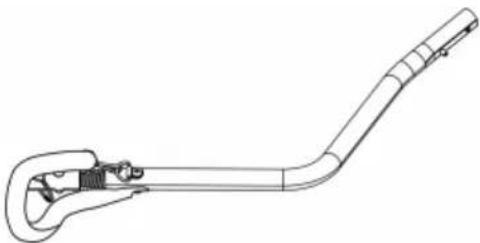
Connect the coupler on the bar and secure the safety pi (Figure 13). Once the tow bar attached, wrap safety belt arou the frame of the bike and hoo onto the D-ring on the tow ba
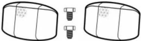
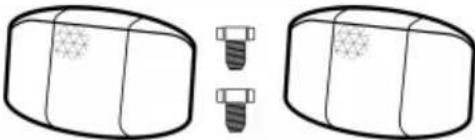
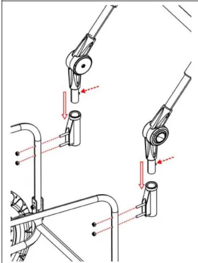
7. Installing the Stroller Kit
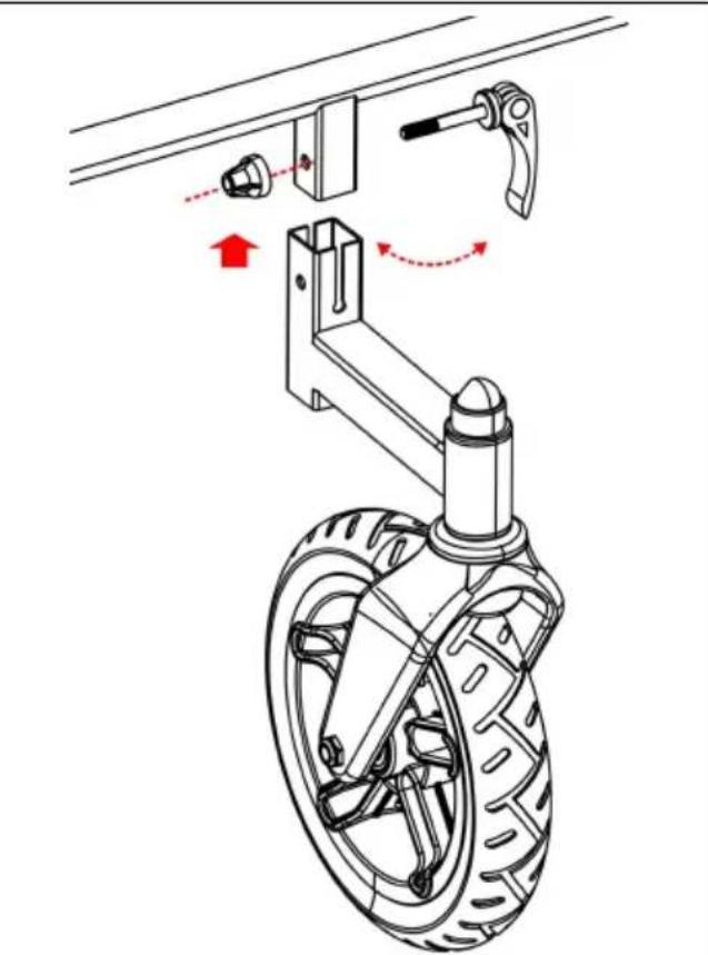
Fix two handle receivers onto the rear tubes of frame by tig nuts. On handle ends, press the spring buttons and slide the into handlebar receivers until two spring buttons pop up through holes (Figure 14). To remove handle, push buttons and pull handle.
Insert the rectangle tube on the front wheel into the rectangle underneath the front frame of the trailer. Make sure that hole rectangle tubes line up. Lock the front wheel using the quick-skewer (Figure 15).
IMPORTANT: Tow bar must be removed before using the stroller
natural_image
Technical diagram of mechanical linkage components with red arrows indicating movement or force (no text or symbols present)Figure 14
natural_image
Mechanical assembly diagram showing a wheel-mounted frame with attached bracket and clamping mechanism (no text or symbols)Figure 15
Before You Ride
Check before each use:
- Wheels are properly secured to the trailer
- Tires are inflated to recommended pressure on the tire side wall
- Tow bar is properly secured to the trailer
- Hitch is properly secured to the bicycle
- All safety pins are securely locked in place.
- Safety strap on the tow bar is properly installed
- Weight of tow bar at coupler is greater than 6.6 lbs. (3 kg) but exceed 17.6 lbs. (8 kg) with fully loaded trailer
- Make sure that bicycle is in proper working order, especially brake and tires (refer to bicycle manufacturer's instructions)
- Safety flag is in place
- Always leash your dog/pet in the trailer.
MAINTENANCE
Storage: For longer product life, store trailer indoors. The trailer should be stored at temperatures less than -10^ F ( -23^ C) or greater than 15^ C ( 65^ C).
Fabric Care: Hand wash fabric parts with warm water and mild soap NOT use bleach or solvents. Wipe dry and store out of direct sunlight dry, well-ventilated area. Clean windows with a damp, soft cloth
VEVOR®
TOUGH TOOLS, HALF PRICE
Technical Support and E-Warranty Certificate
www.vevor.com/support
VEVOR®
TOUGH TOOLS, HALF PRICE
We continue to be committed to provide you tools with competitive price. "Save Half", "Half Price" or any other similar expressions used by us only represent of savings you might benefit from buying certain tools with us compared to top brands and does not necessarily mean to cover all categories of tools offered are kindly reminded to verify carefully when you are placing an order with us actually saving half in comparison with the top major brands.
MODÈLE : TS815

natural_image
Line drawing of a mobile cleaning or cleaning tool with wheels and handle (no text or symbols)NEED HELP? CONTACT US!
Have product questions? Need technical support? Please feel fr contact us:
Technical Support and E-Warranty Certificate www.vevor.com/support
This is the original instruction, please read all manual instruction carefully before operating. VEVOR reserves a clear interpretation user manual. The appearance of the product shall be subject to product you received. Please forgive us that we won't inform you there are any technology or software updates on our product.
CHOOSE THE RIGHT SIZE OF TRAILER

natural_image
Technical diagram showing a bicycle suspension system with a tire and mechanical components, no text or symbols present.Figure 4

Figure 5
natural_image
Technical line drawing of a mechanical assembly with rollers and a housing (no text or symbols)Figure 6
natural_image
Technical line drawing showing two mechanical assembly steps with no visible text or symbolsFigure 7
⚠️ AVERTISSEMENT
natural_image
Line drawing of a vehicle with a flag, showing front wheel, rear wheel, and close-up of mechanical components (no text or symbols)Figure 8

natural_image
Technical line drawing of a wheeled vehicle with a flag and mechanical components (no text or symbols)Figure 9
Figure 10
natural_image
Technical line drawing of a mechanical assembly with no visible text or symbolsFigure 11
⚠ AVERTISSEMENT
natural_image
Technical line drawing of a mechanical linkage assembly (no text or symbols)Figure 12
⚠ AVERTISSEMENT
Figure 13
natural_image
Technical diagram of mechanical assembly with red arrows indicating force or movement (no text or symbols)Figure 14

natural_image
Mechanical assembly diagram showing a wheel-mounted device with attached bracket and lever mechanism (no text or symbols)Figure 1 5
Before You Ride
www.vevor.com/support
We continue to be committed to provide you tools with competitive price. "Save Half", "Half Price" or any other similar expressions used by us only represent of savings you might benefit from buying certain tools with us compared top brands and does not necessarily mean to cover all categories of tools offered are kindly reminded to verify carefully when you are placing an order with us actually saving half in comparison with the top major brands.
MODELL: TS815

natural_image
Line drawing of a mobile cleaning or cleaning tool with wheels and handle (no text or symbols)NEED HELP? CONTACT US!
Have product questions? Need technical support? Please feel fr contact us:
Technical Support and E-Warranty Certificate www.vevor.com/support
This is the original instruction, please read all manual instruction carefully before operating. VEVOR reserves a clear interpretation user manual. The appearance of the product shall be subject to product you received. Please forgive us that we won't inform you there are any technology or software updates on our product.
CHOOSE THE RIGHT SIZE OF TRAILER
natural_image
Technical line drawing of a mechanical assembly with rollers, brackets, and a central component (no text or symbols)Abbildung 6
natural_image
Technical line drawing showing two mechanical assembly steps with no visible text or symbolsAbbildung 7
⚠️ WARNING
natural_image
Technical line drawing of a mechanical assembly with no visible text or symbolsAbbildung 11
⚠️ WARNING
natural_image
Technical line drawing of a mechanical linkage assembly (no text or symbols)Abbildung 12
⚠️ WARNING
www.vevor.com/support
VEVOR®
TOUGH TOOLS, HALF PRICE
www.vevor.com/support
RIMORCHIO PER BICI PER ANIMALI DOMESTICI
MODELLO: TS815
We continue to be committed to provide you tools with competitive price. "Save Half", "Half Price" or any other similar expressions used by us only represent estimate of savings you might benefit from buying certain tools with us compared to top brands and does not necessarily mean to cover all categories of tools offered are kindly reminded to verify carefully when you are placing an order with us actually saving half in comparison with the top major brands.
MODELLO: TS815
natural_image
Line drawing of a mobile cleaning or cleaning tool with wheels and handle (no text or symbols)NEED HELP? CONTACT US!
Have product questions? Need technical support? Please feel fr contact us:
Technical Support and E-Warranty Certificate www.vevor.com/support
This is the original instruction, please read all manual instruction carefully before operating. VEVOR reserves a clear interpretation user manual. The appearance of the product shall be subject to product you received. Please forgive us that we won't inform you there are any technology or software updates on our product.
CHOOSE THE RIGHT SIZE OF TRAILER

MODEL AND PARAMETERS
natural_image
Technical diagram showing a bicycle suspension system with a tire and mechanical components, no text or symbols present.Figura 4

natural_image
Technical diagram showing two mechanical assembly steps: left with a bolt and red arrow indicating direction, right with a pipe inserted into a textured cylindrical component (no text or symbols)Figura 5
natural_image
Technical line drawing of a mechanical assembly with rollers and a housing (no text or symbols)Figura 6
natural_image
Technical line drawing showing two mechanical assembly steps with no visible text or symbolsFigura 7
ATTENZIONE
natural_image
Line drawing of a vehicle with a flag, showing front wheel, rear wheel, and close-up of mechanical components (no text or symbols)Figura 8

natural_image
Technical line drawing of a wheeled vehicle with a flag and mechanical components (no text or symbols)Figura 9
Figura 10
natural_image
Technical line drawing of a mechanical assembly with no visible text or symbolsFigura 11
ATTENZIONE
natural_image
Technical line drawing of a mechanical linkage assembly (no text or symbols)Figura 12
ATTENZIONE
Figura 13
natural_image
Technical diagram of mechanical assembly with red arrows indicating force or movement (no text or symbols)Figura 14

natural_image
Mechanical assembly diagram showing a wheel-mounted device with attached bracket and lever mechanism (no text or symbols)Figura 15
Before You Ride
We continue to be committed to provide you tools with competitive price. "Save Half", "Half Price" or any other similar expressions used by us only represent of savings you might benefit from buying certain tools with us compared to top brands and does not necessarily mean to cover all categories of tools offered are kindly reminded to verify carefully when you are placing an order with us actually saving half in comparison with the top major brands.
MODELO: TS815

natural_image
Line drawing of a mobile cleaning or cleaning tool with wheels and handle (no text or symbols)NEED HELP? CONTACT US!
Have product questions? Need technical support? Please feel fr contact us:
Technical Support and E-Warranty Certificate www.vevor.com/support
This is the original instruction, please read all manual instruction carefully before operating. VEVOR reserves a clear interpretation user manual. The appearance of the product shall be subject to product you received. Please forgive us that we won't inform you there are any technology or software updates on our product.
CHOOSE THE RIGHT SIZE OF TRAILER

natural_image
Technical diagram showing a bicycle suspension system with a tire and mechanical components, no text or symbols present.Figura 4

Figura 5
natural_image
Technical line drawing of a mechanical assembly with rollers and a housing (no text or symbols)Figura 6
natural_image
Technical line drawing showing two mechanical assembly steps with no visible text or symbolsFigura 7
ADVERTENCIA
natural_image
Line drawing of a vehicle with a flag, showing front wheel, rear wheel, and close-up of mechanical components (no text or symbols)Figura 8
natural_image
Technical line drawing of a wheeled vehicle with a flag and mechanical components (no text or symbols)Figura 9
Figura 10
natural_image
Technical line drawing of a mechanical assembly with no visible text or symbolsFigura 11
ADVERTENCIA
natural_image
Technical line drawing of a mechanical linkage assembly (no text or symbols)Figura 12
ADVERTENCIA
Figura 13
natural_image
Technical diagram of mechanical assembly with red arrows indicating force or movement (no text or symbols)Figura 14
natural_image
Mechanical assembly diagram showing a wheel-mounted device with attached bracket and lever mechanism (no text or symbols)Figura 1 5
Before You Ride
www.vevor.com/support
PRZYCZEPKA ROWEROWA DLA ZWIERZAT
MODEL: TS815
We continue to be committed to provide you tools with competitive price. "Save Half", "Half Price" or any other similar expressions used by us only represent of savings you might benefit from buying certain tools with us compared to top brands and does not necessarily mean to cover all categories of tools offered are kindly reminded to verify carefully when you are placing an order with us actually saving half in comparison with the top major brands.
MODEL: TS815

natural_image
Line drawing of a mobile cleaning or cleaning tool with wheels and handle (no text or symbols)NEED HELP? CONTACT US!
Have product questions? Need technical support? Please feel fr contact us:
Technical Support and E-Warranty Certificate www.vevor.com/support
This is the original instruction, please read all manual instruction carefully before operating. VEVOR reserves a clear interpretation user manual. The appearance of the product shall be subject to product you received. Please forgive us that we won't inform you there are any technology or software updates on our product.
CHOOSE THE RIGHT SIZE OF TRAILER

MODEL AND PARAMETERS
natural_image
Technical diagram showing a bicycle suspension system with a tire and mechanical components, no text or symbols present.Rysunek 4
Rysunek 5
natural_image
Technical line drawing of a mechanical assembly with rollers and brackets (no text or symbols)Rysunek 6
natural_image
Technical line drawing showing two mechanical assembly steps with no visible text or symbolsRysunek 7
⚠️ OSTRZEŻENIE
natural_image
Technical line drawing of a mechanical assembly with no visible text or symbolsRysunek 11
⚠️ OSTRZEŻENIE
www.vevor.com/support
VEVOR®
TOUGH TOOLS, HALF PRICE
Technische ondersteuning en e-garantiecertificaat www.vevor.com/support
FIETSKAR VOOR HUISDIEREN
MODEL: TS815
We continue to be committed to provide you tools with competitive price. "Save Half", "Half Price" or any other similar expressions used by us only represent estimate of savings you might benefit from buying certain tools with us compared top brands and does not necessarily mean to cover all categories of tools offered are kindly reminded to verify carefully when you are placing an order with us actually saving half in comparison with the top major brands.
MODEL: TS815

natural_image
Line drawing of a mobile cleaning or cleaning tool with wheels and handle (no text or symbols)NEED HELP? CONTACT US!
Have product questions? Need technical support? Please feel fr contact us:
Technical Support and E-Warranty Certificate www.vevor.com/support
This is the original instruction, please read all manual instruction carefully before operating. VEVOR reserves a clear interpretation user manual. The appearance of the product shall be subject to product you received. Please forgive us that we won't inform you there are any technology or software updates on our product.
CHOOSE THE RIGHT SIZE OF TRAILER

| Aanhangwagengrootte | X- groot |
| Max. Lichaamslengte | 3 5 inch ( 9 0 |
| Max. Schouder hoogte | 24 inch ( 61 c |
| Max. Gewicht | 100 pond. ( 45 |
SAFETY INSTRUCTIONS
⚠ WAARSCHUWING
natural_image
Technical line drawing of a mechanical device with internal components and red motion arrows indicating movement (no text or symbols)Figuur 1
natural_image
Diagram of a mechanical linkage system with a red arrow indicating rotation (no text or symbols)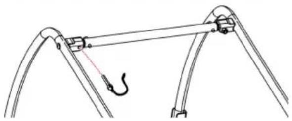
natural_image
Diagram of a mechanical linkage system with a hook and connecting rods (no text or symbols)Figuur 2
natural_image
Simple line drawing of a mechanical clamp or bracket with a green checkmark (no text or symbols)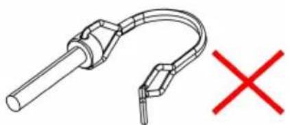
natural_image
Pure diagram of a curved mechanical component with a red X mark, no text or symbols presentFiguur 3
natural_image
Technical diagram showing a bicycle suspension system with a tire and mechanical components, no text or symbols present.Figuur 4

natural_image
Technical diagram showing two mechanical assembly steps: left with a screw and red arrow indicating direction, right with a shaft and red arrow indicating displacement (no text or symbols)Figuur 5
natural_image
Technical line drawing of a mechanical assembly with rollers and brackets (no text or symbols)Figuur 6
natural_image
Technical line drawing showing mechanical assembly with no visible text or symbolsFiguur 7
⚠ WAARSCHUWING
Figuur 8
natural_image
Technical line drawing of a wheeled vehicle with a flag and mechanical components (no text or symbols)Figuur 9
Figuur 10
natural_image
Technical line drawing of a mechanical assembly with no visible text or symbolsFiguur 11
⚠ WAARSCHUWING
natural_image
Technical line drawing of a mechanical linkage assembly (no text or symbols)Figuur 12
⚠ WAARSCHUWING
natural_image
Mechanical assembly diagram showing a motor, suspension rod, and spring mechanism (no text or labels)
natural_image
Mechanical assembly diagram showing gear and linkage components with red dotted arrows indicating motion paths (no text or labels)Figuur 13
natural_image
Mechanical assembly diagram showing two connected pipe fittings with red arrows indicating motion or force directions (no text or symbols present)Figuur 14
natural_image
Mechanical assembly diagram showing a wheel-mounted device with attached bracket and lever mechanism (no text or symbols)Figuur 1 5
Before You Ride
www.vevor.com/support
VEVOR®
TOUGH TOOLS, HALF PRICE
www.vevor.com/support
HUSDJURSCYKELVAGN
MODELL: TS815
We continue to be committed to provide you tools with competitive price. "Save Half", "Half Price" or any other similar expressions used by us only represent estimate of savings you might benefit from buying certain tools with us compared to top brands and does not necessarily mean to cover all categories of tools offered are kindly reminded to verify carefully when you are placing an order with us actually saving half in comparison with the top major brands.
MODELL: TS815

natural_image
Line drawing of a mobile cleaning or cleaning tool with wheels and handle (no text or symbols)NEED HELP? CONTACT US!
Have product questions? Need technical support? Please feel fr contact us:
Technical Support and E-Warranty Certificate www.vevor.com/support
This is the original instruction, please read all manual instruction carefully before operating. VEVOR reserves a clear interpretation user manual. The appearance of the product shall be subject to product you received. Please forgive us that we won't inform you there are any technology or software updates on our product.
CHOOSE THE RIGHT SIZE OF TRAILER

natural_image
Technical line drawing of a mechanical device with internal components and red motion arrows indicating movement (no text or symbols)Figur 1
natural_image
Technical line drawing of a mechanical linkage assembly with a red arrow indicating motion direction (no text or symbols)Figur 2
natural_image
Technical line drawing of a mechanical clamp with checkmark and cross symbols (no text or labels)Figur 3
51. Fästa hjulen
natural_image
Technical line drawing of a bicycle suspension system with a tire and bracket assembly (no text or symbols)Figur 4
natural_image
Technical diagram showing two mechanical assembly steps: left with a bolt and red arrow indicating downward motion, right with a pipe inserted into a textured cylindrical component (no text or symbols)Bild 5
natural_image
Technical line drawing of a mechanical assembly with rollers and brackets (no text or symbols)Bild 6
natural_image
Technical line drawing showing two mechanical assembly steps with no visible text or symbolsBild 7
WARNING
Bild 8
natural_image
Technical line drawing of a wheeled vehicle with a flag and mechanical components (no text or symbols)Bild 9
Bild 10
natural_image
Technical line drawing of a mechanical assembly with no visible text or symbolsBild 11
WARNING
natural_image
Technical diagram of mechanical linkage components with red arrows indicating movement or force (no text or symbols present)Bild 14

natural_image
Mechanical assembly diagram showing a wheel-mounted frame with mounting bracket and adjustment mechanism (no text or symbols)Bild 1 5
Before You Ride
www.vevor.com/support