UL500P - Emergency exit device Vevor - Free user manual and instructions
Find the device manual for free UL500P Vevor in PDF.

| Product Type | Emergency Exit Device (Panic Bar) |
| Brand | Vevor |
| Model | UL500P |
| Material | Carbon Steel |
| Length | 27.5 inches (698.5 mm) |
| Compatible Door Width | 28 to 41 inches (711 to 1041 mm) |
| Compatible Door Thickness | 1 37/64 to 2 11/64 inches (approx. 39 to 55 mm) |
| Surface Finish | Powder Coating (Epoxy Paint) |
| Mechanism | Deadbolt Latch (Roller Strike) |
| Application | Swinging Emergency Exit Doors |
| Manual Locking | Yes, with wrench (counterclockwise rotation to lock) |
| Installation | Requires drilling and screwing, detailed instructions provided |
| Maintenance | Periodic check of screw tightening |
| Safety Precautions | Keep small parts away from children, do not use by children |
| Technical Support | Vevor website: www.vevor.com/support |
Frequently Asked Questions - UL500P Vevor
User questions about UL500P Vevor
0 question about this device. Answer the ones you know or ask your own.
Ask a new question about this device
Download the instructions for your Emergency exit device in PDF format for free! Find your manual UL500P - Vevor and take your electronic device back in hand. On this page are published all the documents necessary for the use of your device. UL500P by Vevor.
USER MANUAL UL500P Vevor
Technical Support and E-Warranty Certificate www.vevor.com/support
Panic Exit Device User Manual
MODEL:UL500P
We continue to be committed to provide you tools with competitive price. "Save Half", "Half Price" or any other similar expressions used by us only represent of savings you might benefit from buying certain tools with us compared top brands and does not necessarily mean to cover all categories of tools offered are kindly reminded to verify carefully when you are placing an order with us actually saving half in comparison with the top major brands.
VEVOR®
TOUGH TOOLS, HALF PRICE
Panic Exit Device
MODEL:UL500P
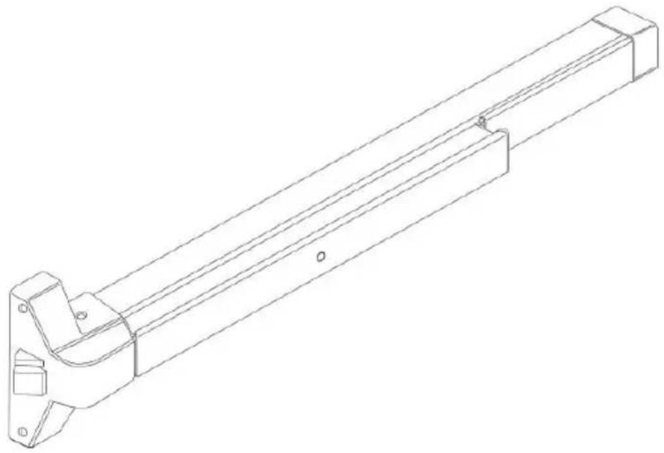
natural_image
Technical line drawing of a mechanical bracket or support structure (no text or symbols)NEED HELP? CONTACT US!
Have product questions? Need technical support? Please feel fr contact us:
Technical Support and E-Warranty Certificate www.vevor.com/support
This is the original instruction, please read all manual instruction carefully before operating. VEVOR reserves a clear interpretation user manual. The appearance of the product shall be subject to product you received. Please forgive us that we won't inform you there are any technology or software updates on our product.
WARNING
-
Read carefully and understand all ASSEMBLY AND OPERATION INSTRUCTIONS before operating.
-
Failure to follow the safety rules and other basic safety precautions result in serious personal injury.
GENERAL SAFETY RULES
-
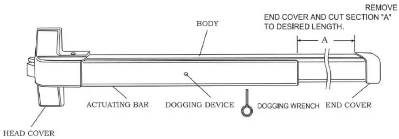
To extend the life of this panic device, lock the latch in the retra position when the door is in continuous use.
-
To Lock
Hold the actuating bar down. Turn the dogging device counterclockw with a dogging wrench.
- To Unlock
Hold the actuating bar down. Turn the dogging device clockwise with dogging wrench.
-
Assemble only according to these instructions. Improper assembly c create hazards.
-
Keep assembly area clean and well lit.
-
Keep bystanders out of the area during assembly.
-
Do not assemble when tired or when under the influence of alcohol drugs or medication.
-
This product contains small parts. If swallowed, it will pose a chol hazard. Keep these small parts away from children when assembling! is not a toy. Not for use by children.
SAVE THESE INSTRUCTIONS
MODEL AND PARAMETERS
| Model | UL500P |
| Product Spec | 27.5” |
| Material | Carbon Steel |
| Suitable for Door | 28"~41" |
| Suitable door thickness | 1 37/64"~2 11/64" |
| Surface Finish | Surface Powder Spraying |
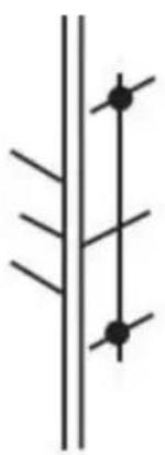
STRUCTURE DIAGRAM
OPERATING INSTRUCTIONS
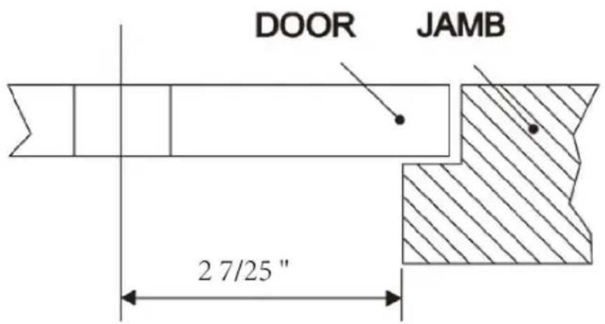
Step1: Installation distance determination.

Step2: Mark the corresponding holes on the door according to the dimensional drawing.
Note:"B" length should be measured from the center of cylinder hole end of the body.
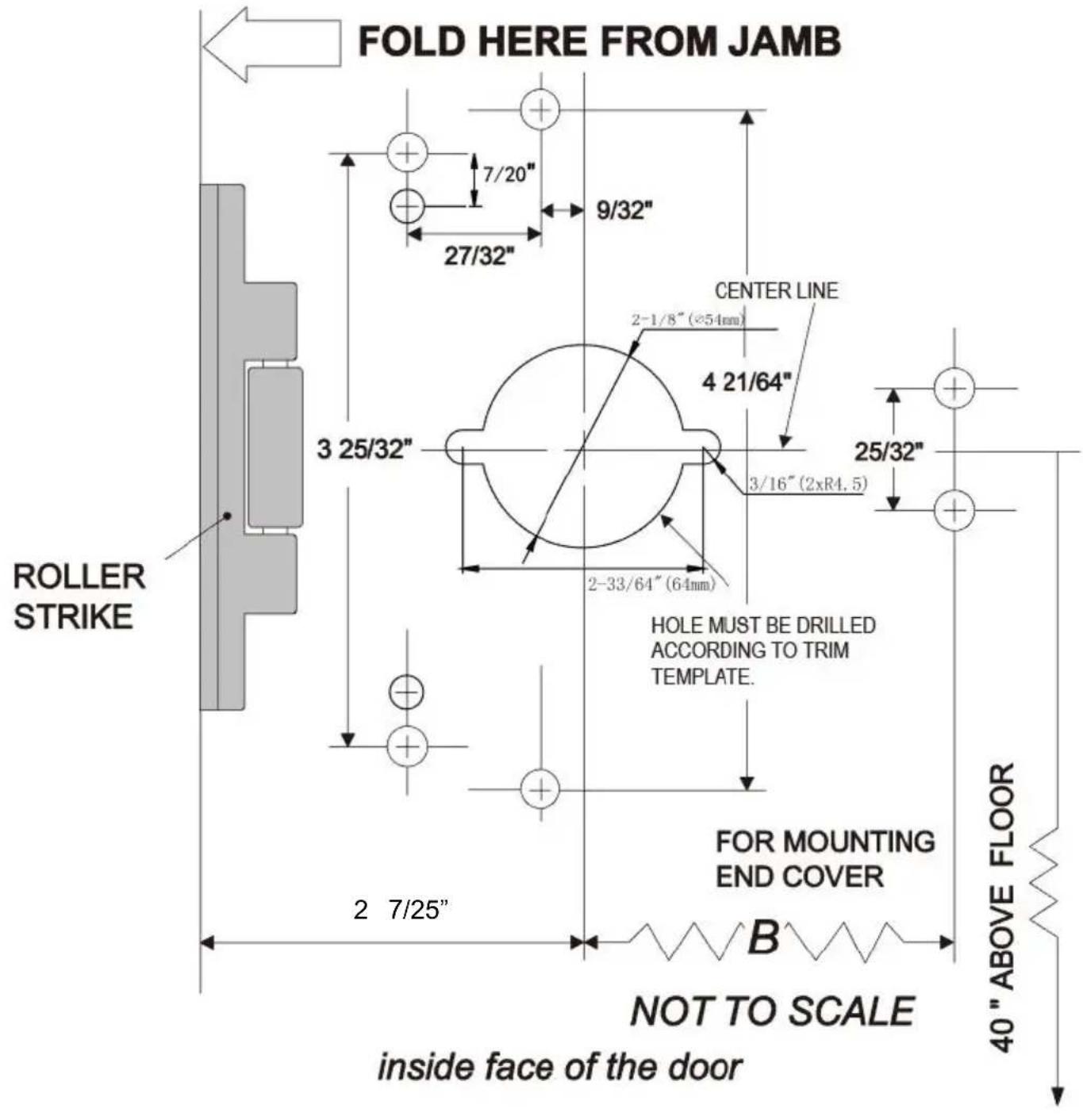
Step3: Insert the lever trim into the hole on the door. Keep the leve horizontal. Tighten the screws.
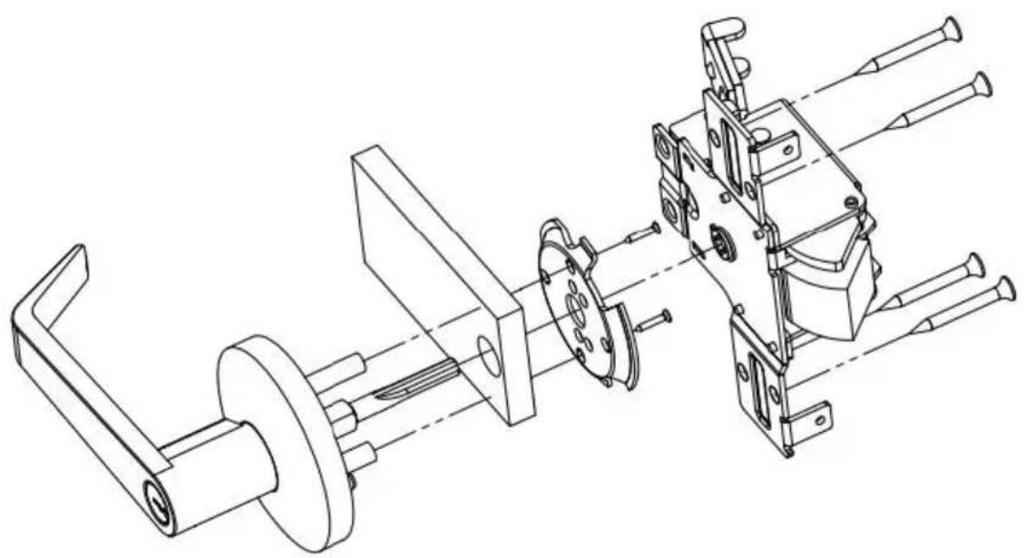
natural_image
Technical line drawing of a mechanical assembly with exploded view (no text or symbols)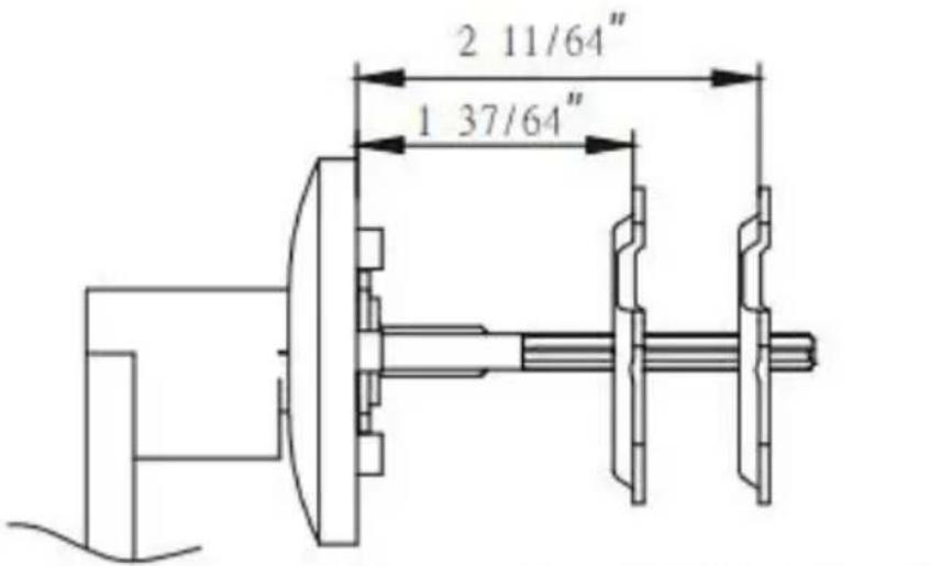
For a door thickness of 1 37/64"\~2 11/64"
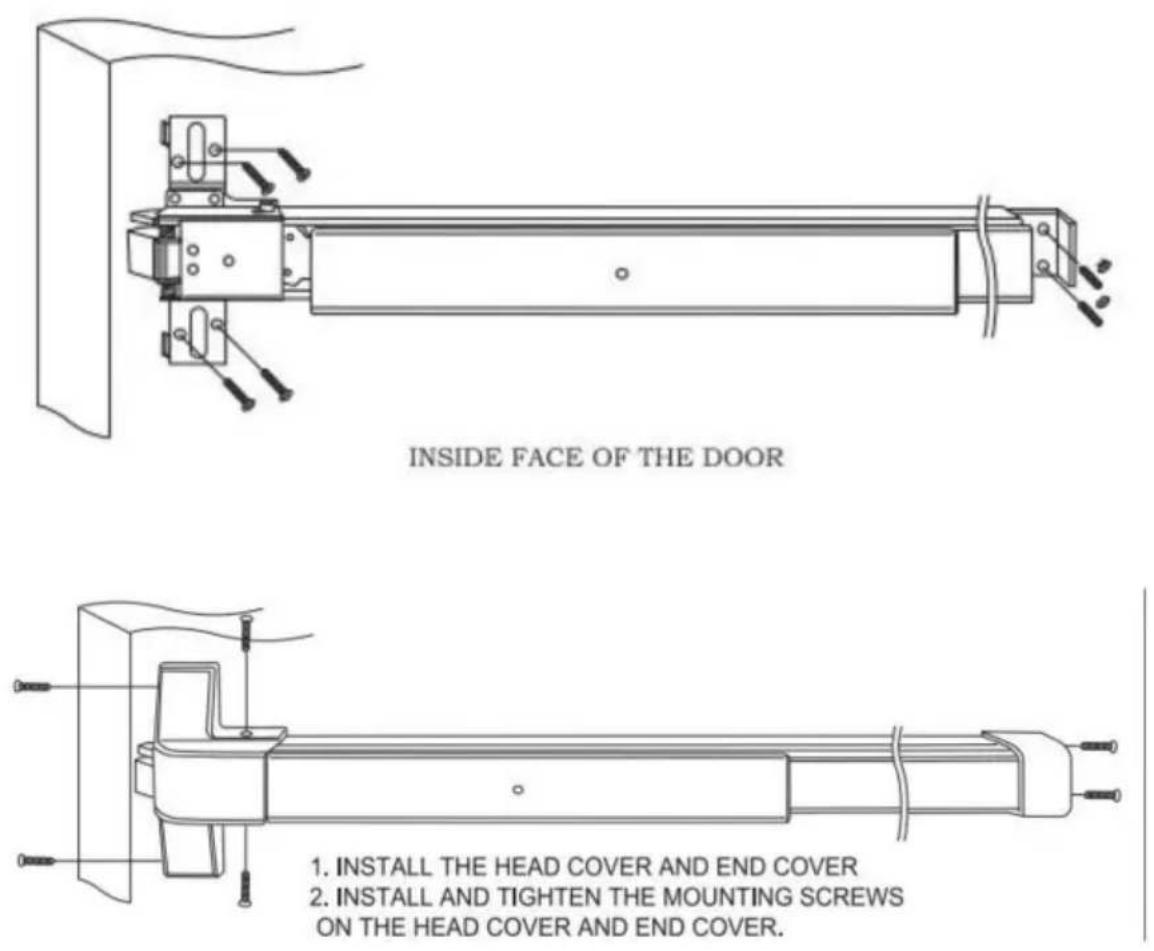
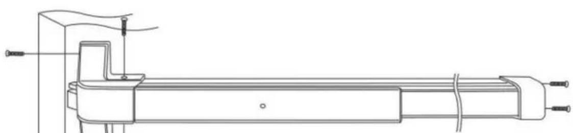
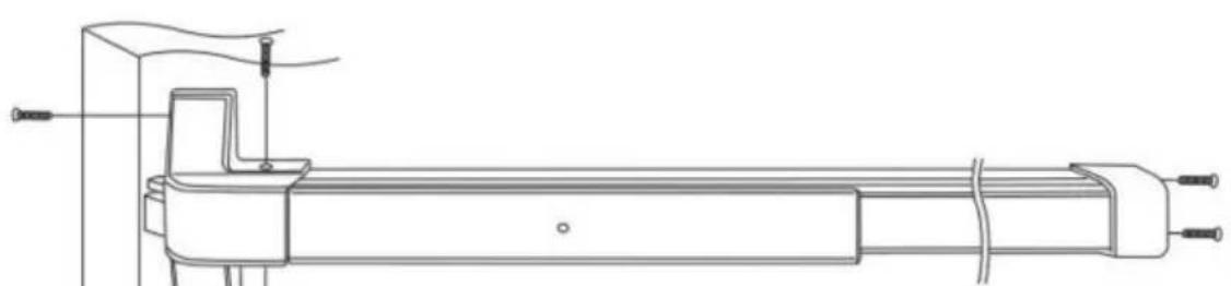
Step4: Remove the head cover and the screws on the end cover. All screw holes with the holes on the door. Tighten the screws on the lining of end cover.
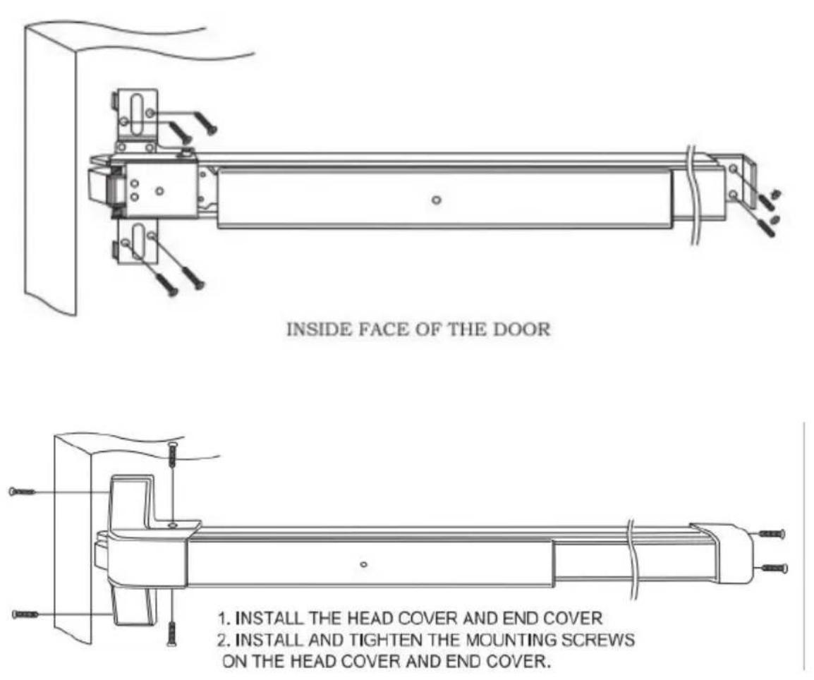
1. INSTALL THE HEAD COVER AND END COVER
2. INSTALL AND TIGHTEN THE MOUNTING SCREWS
ON THE HEAD COVER AND END COVER.
-
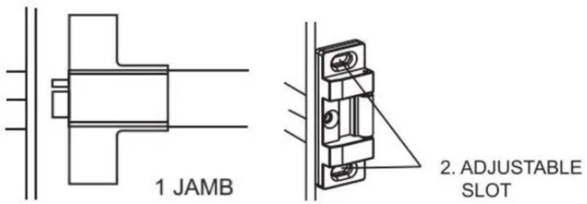
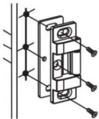
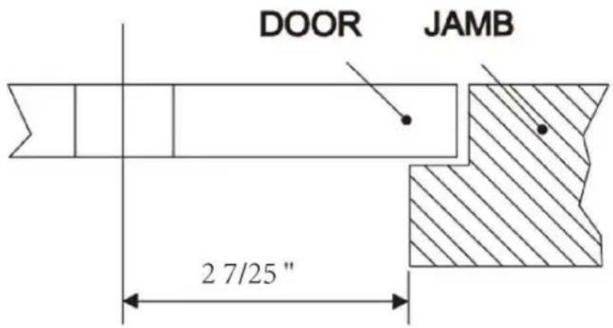
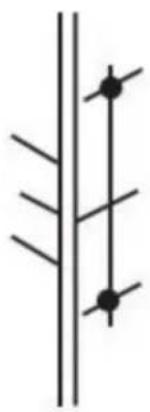
With the door in the closed position, mark the center line of latch door JAMB.
-
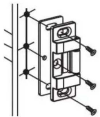
Place roller strike on door JAMB. Align the center of the roller strike the latch bolt center line mark on the JAMB. Then align the outside the roller strike with the outside edge of the door JAMB.
-
Mark the center of the 2 adjustable slotted holes and drill 7/32" pil Tap pilot holes with 1/4"-20 threads and install machine screws. Or in self-tapping machine screws or wood screws in pilot holes. Close the to check if the latch bolt extends properly. Adjust the roller strike if necessary.
-
With roller strike in final position. Drill a 7 /32" pilot hole for the mounting hole. Tap the pilot hole with 1/4-20 threads and install machine screws. Or install self -tapping machine screws or wood screws in pilholes.
natural_image
Pure electrical circuit lines without any symbols- DRILL 7/32" HOLE, TAP 1/4"-20P THREAD
natural_image
Technical line drawing of a mechanical assembly with mounting holes and housing (no text or symbols)- 1/4"-20P FLAT HEAD SCREW
MAINTENANCE
1..All maintenance, service, and repairs not discussed in the manual should be performed by qualified service technicians.
- Check the product regularly to prevent screws from loosening and falling off.
Manufacturer:
JIANGSU TONGGUAN INTELLIGENT TECHNOLOGYCO.,LTD
Address:
800 BIHUA ROAD, TONGZHOU DISTRICT,NANTONG,JIANGSU
PROVINCE,CHINA
SHUNSHUN GmbH
Römeräcker 9 Z2021,76351
Unit 5 Albert Edward House, The
Pavilions Preston, United Kingdom
Made in China
VEVOR®
TOUGH TOOLS, HALF PRICE
Technical Support and E-Warranty Certificate
www.vevor.com/support
VEVOR®
TOUGH TOOLS, HALF PRICE
natural_image
Technical line drawing of a mechanical bracket or support structure (no text or symbols)ISTRUZIONI PER L'USO

natural_image
Technical line drawing of a mechanical assembly with exploded view (no text or symbols)
For a door thickness of 1 37/64"\~2 11/64"
natural_image
Technical line drawing of a mechanical assembly with mounting holes and a triangular load, no text or symbols present- ADJUSTABLE SLOT

natural_image
Pure electrical circuit lines without any symbols- DRILL 7/32" HOLE, TAP 1/4"-20P THREAD

natural_image
Technical line drawing of a mechanical assembly with mounting holes and vertical supports (no text or symbols)- 1/4"-20P FLAT HEAD SCREW
MANUTENZIONE
Unit 5 Albert Edward House, The
Pavilions Preston, United Kingdom
Made in China
VEVOR®
TOUGH TOOLS, HALF PRICE
elettronica www.vevor.com/support
VEVOR®
TOUGH TOOLS, HALF PRICE
natural_image
Technical line drawing of a mechanical bracket or support structure (no text or symbols)POTRZEBUJESZ POMOCY? SKONTAKTUJ SIĘ Z NAMI!
INSTRUKCJA OBSŁUGI

natural_image
Technical line drawing of a mechanical assembly with exploded view (no text or symbols)
For a door thickness of 1 37/64"\~2 11/64"
1. INSTALL THE HEAD COVER AND END COVER
2. INSTALL AND TIGHTEN THE MOUNTING SCREWS
ON THE HEAD COVER AND END COVER.
INSTALACJA ZACZEPU ROLKOWEGO
natural_image
Technical line drawing of a mechanical assembly with mounting holes and a triangular load, no text or symbols present- ADJUSTABLE SLOT
KONSERWACJA
natural_image
Technical line drawing of a mechanical bracket or support structure (no text or symbols)BESOIN D'AIDE? CONTACTEZ-NOUS!
MODE D'EMPLOI

natural_image
Technical line drawing of a mechanical assembly with exploded view (no text or symbols)
For a door thickness of 1 37/64"\~2 11/64"
natural_image
Technical line drawing of a mechanical assembly with no visible text or symbolsINSIDE FACE OF THE DOOR
natural_image
Technical line drawing of a mechanical device with no visible text or symbols- INSTALL THE HEAD COVER AND END COVER
- INSTALL AND TIGHTEN THE MOUNTING SCREWS
ON THE HEAD COVER AND END COVER.
natural_image
Technical line drawing of a mechanical assembly with mounting holes and a triangular load, no text or symbols present- ADJUSTABLE SLOT

natural_image
Pure electrical circuit lines without any symbols- DRILL 7/32" HOLE, TAP 1/4"-20P THREAD

natural_image
Technical line drawing of a mechanical assembly with mounting holes and vertical supports (no text or symbols)- 1/4"-20P FLAT HEAD SCREW
ENTRETIEN
Unit 5 Albert Edward House, The
Pavilions Preston, United Kingdom
Fabriqué en Chine
VEVOR®
TOUGH TOOLS, HALF PRICE
natural_image
Technical line drawing of a mechanical bracket or support structure (no text or symbols)BEDIENUNGSANLEITUNG

natural_image
Technical line drawing of a mechanical assembly with exploded view (no text or symbols)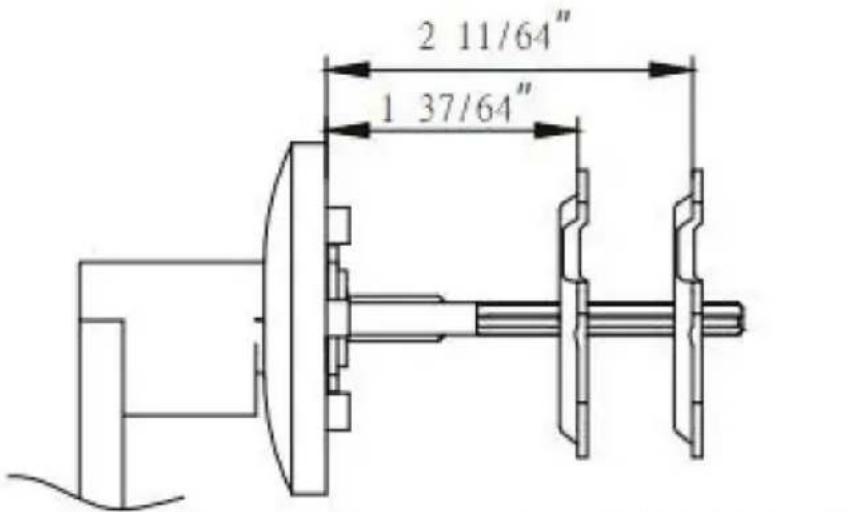
For a door thickness of 1 37/64"\~2 11/64"
natural_image
Technical line drawing of a mechanical assembly with no visible text or symbolsINSIDE FACE OF THE DOOR
natural_image
Technical line drawing of a mechanical assembly with no visible text or symbols-
INSTALL THE HEAD COVER AND END COVER
-
INSTALL AND TIGHTEN THE MOUNTING SCREWS ON THE HEAD COVER AND END COVER.
natural_image
Technical line drawing of a mechanical assembly with mounting holes and a triangular load, no text or symbols present- ADJUSTABLE SLOT

natural_image
Pure electrical circuit lines without any symbols- DRILL 7/32" HOLE, TAP 1/4"-20P THREAD

natural_image
Technical line drawing of a mechanical assembly with mounting holes and vertical supports (no text or symbols)- 1/4"-20P FLAT HEAD SCREW
WARTUNG
Unit 5 Albert Edward House, The
Pavilions Preston, United Kingdom
www.vevor.com/support
VEVOR®
TOUGH TOOLS, HALF PRICE
Technische ondersteuning en e-garantiecertificaat www.vevor.com/support
natural_image
Technical line drawing of a mechanical bracket or support structure (no text or symbols)HULP NODIG? NEEM CONTACT MET ONS OP!
GEBRUIKSAANWIJZING
natural_image
Technical line drawing of a mechanical assembly with exploded view (no text or symbols)
For a door thickness of 1 37/64"\~2 11/64"
natural_image
Technical line drawing of a mechanical assembly with no visible text or symbolsINSIDE FACE OF THE DOOR

natural_image
Technical line drawing of a mechanical assembly with no visible text or symbols-
INSTALL THE HEAD COVER AND END COVER
-
INSTALL AND TIGHTEN THE MOUNTING SCREWS ON THE HEAD COVER AND END COVER.
ROLLER STRIKE INSTALLATIE
natural_image
Technical line drawing of a mechanical assembly with mounting holes and a triangular load, no text or symbols present- ADJUSTABLE SLOT
natural_image
Pure electrical circuit lines without any symbols- DRILL 7/32" HOLE, TAP 1/4"-20P THREAD
natural_image
Technical line drawing of a mechanical assembly with mounting holes and vertical supports (no text or symbols)- 1/4"-20P FLAT HEAD SCREW
ONDERHOUD
Unit 5 Albert Edward House, The
Pavilions Preston, United Kingdom
Gemaakt in China
VEVOR®
TOUGH TOOLS, HALF PRICE
garantiecertificaat www.vevor.com/support
VEVOR®
TOUGH TOOLS, HALF PRICE
natural_image
Technical line drawing of a mechanical bracket or support structure (no text or symbols)BEHÖVER HJÄLP? KONTAKTA OSS!
DRIFTSINSTRUKTIONER

natural_image
Technical line drawing of a mechanical assembly with exploded view (no text or symbols)
For a door thickness of 1 37/64"\~2 11/64"
natural_image
Technical line drawing of a mechanical assembly with no visible text or symbolsINSIDE FACE OF THE DOOR

natural_image
Technical line drawing of a mechanical assembly with no visible text or symbols- INSTALL THE HEAD COVER AND END COVER
- INSTALL AND TIGHTEN THE MOUNTING SCREWS
ON THE HEAD COVER AND END COVER.
natural_image
Pure electrical circuit lines without any symbols- DRILL 7/32" HOLE, TAP 1/4"-20P THREAD

natural_image
Technical line drawing of a mechanical assembly with mounting holes and vertical supports (no text or symbols)- 1/4"-20P FLAT HEAD SCREW
UNDERHÅLL
Unit 5 Albert Edward House, The
Pavilions Preston, United Kingdom
Tillverkad i Kina
VEVOR®
TOUGH TOOLS, HALF PRICE
www.vevor.com/support
VEVOR®
TOUGH TOOLS, HALF PRICE
natural_image
Technical line drawing of a mechanical bracket or support structure (no text or symbols)INSTRUCCIONES DE USO

natural_image
Technical line drawing of a mechanical assembly with exploded view (no text or symbols)
For a door thickness of 1 37/64"\~2 11/64"
natural_image
Technical line drawing of a mechanical assembly with no visible text or symbolsINSIDE FACE OF THE DOOR

natural_image
Technical line drawing of a mechanical assembly with no visible text or symbols- INSTALL THE HEAD COVER AND END COVER
- INSTALL AND TIGHTEN THE MOUNTING SCREWS
ON THE HEAD COVER AND END COVER.
natural_image
Technical line drawing of a mechanical assembly with mounting holes and a triangular load, no text or symbols present- ADJUSTABLE SLOT

natural_image
Pure electrical circuit lines without any symbols- DRILL 7/32" HOLE, TAP 1/4"-20P THREAD

natural_image
Technical line drawing of a mechanical assembly with mounting holes and vertical supports (no text or symbols)- 1/4"-20P FLAT HEAD SCREW
MANTENIMIENTO
Unit 5 Albert Edward House, The
Pavilions Preston, United Kingdom
Hecho en china
VEVOR®
TOUGH TOOLS, HALF PRICE