
SC1402 - Vehicle accessory Vevor - Free user manual and instructions
Find the device manual for free SC1402 Vevor in PDF.

User questions about SC1402 Vevor
0 question about this device. Answer the ones you know or ask your own.
Ask a new question about this device
Download the instructions for your Vehicle accessory in PDF format for free! Find your manual SC1402 - Vevor and take your electronic device back in hand. On this page are published all the documents necessary for the use of your device. SC1402 by Vevor.
USER MANUAL SC1402 Vevor
Technical Support and E-Warranty Certificate www.vevor.com/support
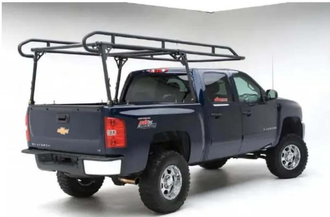
OVER-CAB TRUCK RACK
MODEL:SC1402
We continue to be committed to provide you tools with competitive price. "Save Half", "Half Price" or any other similar expressions used by us only rep estimate of savings you might benefit from buying certain tools with us compared top brands and does not necessarily mean to cover all categories of tools offered are kindly reminded to verify carefully when you are placing an order with us actually saving half in comparison with the top major brands.
MODEL: SC1402
natural_image
Side view of a dark blue pickup truck with a metal roof rack and front livery (no visible text or symbols)NEED HELP? CONTACT US!
Have product questions? Need technical support? Please feel fr contact us:
Technical Support and E-Warranty Certificate www.vevor.com/support
This is the original instruction, please read all manual instruction carefully before operating. VEVOR reserves a clear interpretation user manual. The appearance of the product shall be subject to product you received. Please forgive us that we won't inform you there are any technology or software updates on our product.
IMPORTANT SAFEGUARDS

WARNING: Read and understand this entire manual before operating or servicing this product. Failure to follow these warnings and instructions can cause personal injury or damage to valuable proper
- Avoid children using the product. And this product is not a toy. Do not all children to play.
- It is highly recommended to go to a professional auto repair shop for replacement installation.
Assembly precautions
- Assemble only according to these instructions. Improper assembly can create hazards.
- Wear ANSI-approved safety goggles and heavy-duty work gloves during assembly and use.
- Keep the assembly area clean and well-lit.
- Keep bystanders out of the area during assembly.
- Do not assemble when tired or when under the influence of alcohol, drug medication.
- Product capabilities apply to properly and completely assembled product only
- For additional information regarding the parts listed in the following pages, please refer to the Assembly Diagram of this manual. Unwrap and separate parts in a clean work area. Please keep small spare parts out of children's
- Inspect the product before use to ensure it is assembled properly and all are in safe working order and free of defects.
- Never modify this product in any way.
- All circumstances cannot be addressed in these instructions. Please use common sense and practice general safety measures when using this product.
SAVE THESE INSTRUCTIONS
SAFETY AND USE
- Do not exceed the carrying capacity of 1000 lbs. Doing so could result in property damage or personal injury.
- The truck rack adds more weight to your vehicle and raises the center of gravity when loaded. Use caution when making sharp turns to prevent product damage, cargo loss, or the vehicle from rolling over.
- Ensure the cab hoop does not come in contact with the truck cab to pre property damage.
- Use sufficient tie-down straps when transporting cargo on the truck rack (T product does not contain).
- Be sure all nuts and bolts are tight on a regular basis and no foreign oil are preventing the rack from sitting or working properly.
- Scratches and dents should be inspected to ensure full usability and exposure metal should be touched up/painted to deter rusting.
SPECIFICATION
| Model | SC1402 |
| Material | Steel |
| Max Load | 1000lbs/454kg |
| Installation Width Range | 1100~1600mm |
| Installation Length Range | 1600-1900mm |
| Color | Black |
PACKAGE LIST
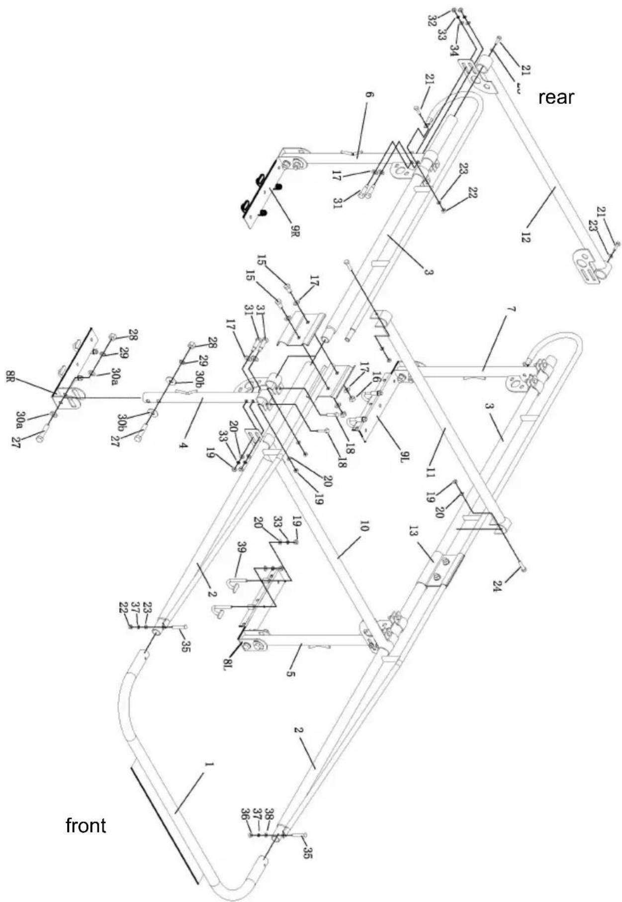
Fig.A
| Table 1 | ||||||
| No. | Name | QTY | No. | Name | QTY | |
| 1 | Cab Bar | 1 | 23 | Flat Washer:φ10 | 6 | |
| 2 | Front Side Frames | 2 | 24 | Bolt:M12*75 | 2 | |
| 3 | Back Side Frames | 2 | 27 | Bolt:M18*90 | 8 | |
| 4 | front right leg Stand | 1 | 28 | Nut:M18 | 8 | |
| 5 | front left leg Stand | 1 | 29 | Spring Washer:φ18 | 8 | |
| 6 | Rear right leg Stand (with welded tip) | 1 | 30a | Flat Washer:φ18 | 8 | |
| 7 | Rear left leg Stand (with welded tip) | 1 | 30b | Flat Washer:φ18 | 8 | |
| 8L,8R | Front Mounting Feet | 2 | 31 | Bolt:M12*70 | 8 | |
| 9L,9R | Rear Mounting Feet | 2 | 33 | Spring Washer:φ12 | 16 | |
| 10 | Front Bar | 1 | 35 | Bolt:M10*70 | 2 | |
| 11 | Center Bar | 1 | 37 | Spring Washer:φ10 | 2 | |
| 12 | Rear Cross Bar | 1 | 39 | J-Hook (M12) | 8 | |
| 13 | Clamps | 4 | ||||
| 15 | Bolt:M16*30 | 4 | ||||
| 16 | Nut:M16 | 4 | ||||
| 17 | Flat Washer:φ16 | 16 | ||||
| 18 | Bolt:M12*50 | 8 | ||||
| 19 | Nut:M12 | 26 | ||||
| 20 | Flat Washer:φ12 | 26 | ||||
| 21 | Bolt:M10*30 | 4 | ||||
| 22 | Nut:M10 | 4 | ||||
Accessory bolts are configured as components for easy use. See Table 2 and
| Table 2 | |||
| No. | Specification | QTY | Correspond to the numbers in Tab |
| A | Bolt:M16*30 | 4 | #15 |
| Nut:M16 | 4 | #16 | |
| Flat Washer:φ16 | 8 | #17 | |
| B | Bolt:M12*50 | 8 | #18 |
| Nut:M12 | 8 | #19 | |
| Flat Washer:φ12 | 8 | #20 | |
| C | Bolt:M10*30 | 2 | #21 |
| Flat Washer:φ10 | 2 | #23 | |
| D | Bolt:M10*30 | 2 | #21 |
| Nut:M10 | 2 | #22 | |
| Flat Washer:φ10 | 2 | #23 | |
| E | Bolt:M12*75 | 2 | #24 |
| Nut:M12 | 2 | #19 | |
| Flat Washer:φ12 | 2 | #20 | |
| F1/F2 | Bolt:M18*90 | 8 | #27 |
| Nut:M18 | 8 | #28 | |
| Spring Washer:φ18 | 8 | #29 | |
| Flat Washer:φ18 | 16 | #30a/#30b | |
| G | Bolt:M12*70 | 8 | #31 |
| Nut:M12 | 8 | #19 | |
| Spring Washer:φ12 | 8 | #33 | |
| Flat Washer:φ12 | 8 | #20 | |
| Flat Washer:φ16 | 8 | #17 | |
| H | Carry Bolt:M10*70 | 2 | #35 |
| Nut:M10 | 2 | #22 | |
| Spring Washer:φ10 | 2 | #37 | |
| Flat Washer:φ10 | 2 | #23 | |
| J | “J” Hook(M12) | 8 | #39 |
| Nut:M12 | 8 | #19 | |
| Spring Washer:φ12 | 8 | #33 | |
| Flat Washer:φ12 | 8 | #20 | |
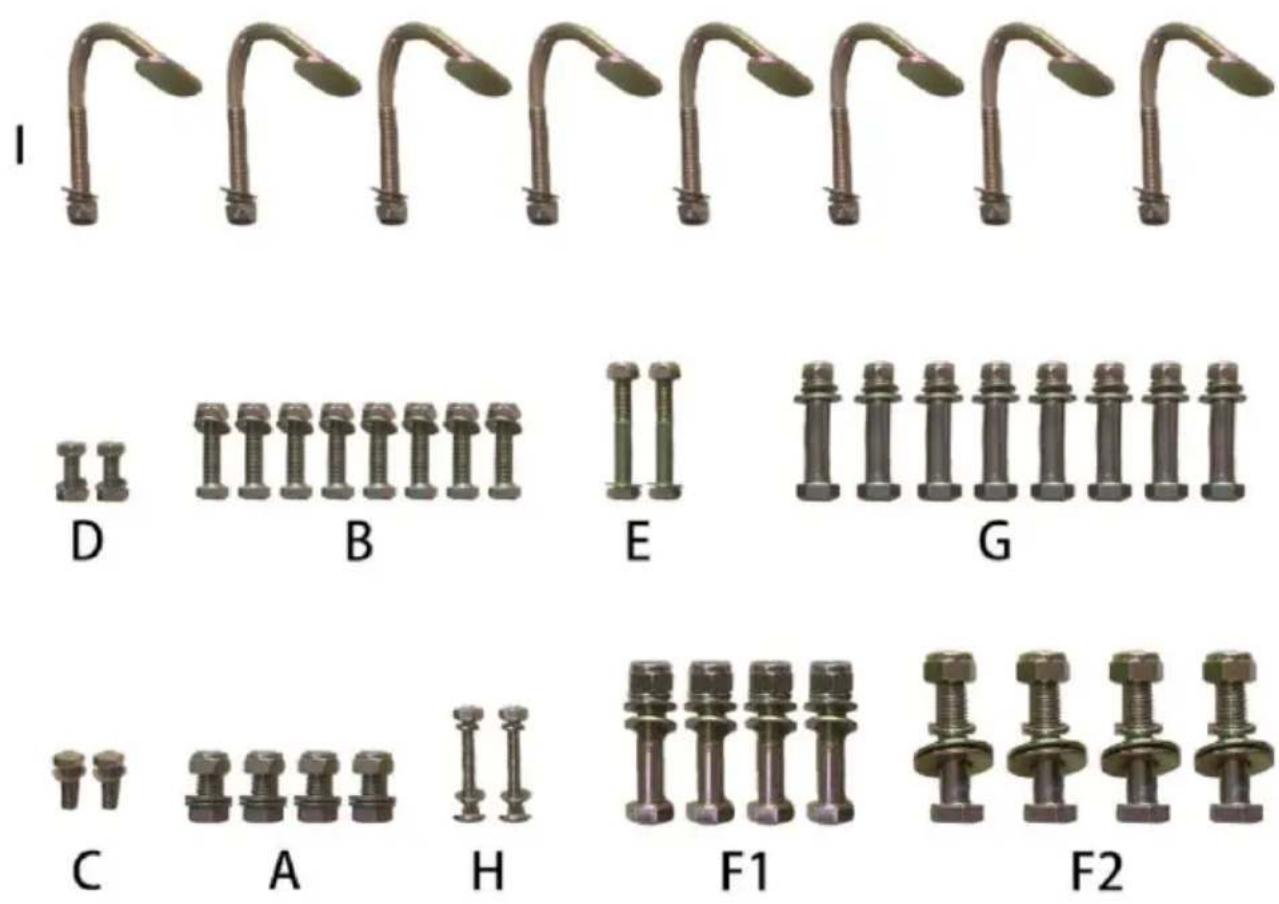
Fig.B
ASSEMBLE
NOTE: It is recommended to have an assistant while assembling and installing this product.
STEP 1:
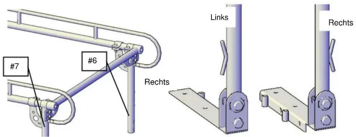
Slide the Rear Left leg Stand (#7) onto the Back Side Frames (#3), then sl rear cross bar (#12) over the end of the Back Side Frames. (Fig. 1)
Attach using the 2-M12x70 bolts (#31), flat washer(17)(20) ,spring washer(33) Nut(19) (see the Accessory bolt set"G") Tighten snug but not completely.
Attach using the 2-M12x50 bolts(#18), flat washer(20) and Nut(19) (see the Accessory bolt set"B") Tighten snug but not completely.
Attach using the M10x35 bolts(#21), flat washer(23) (see the Accessory bolt s Tighten snug but not completely.(Fig.2)
Repeat same steps for rear right side. (Fig.3)
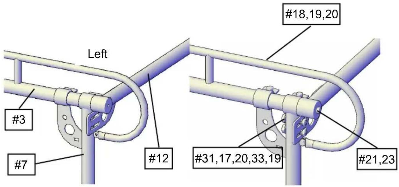
Fig.1 Fig.2
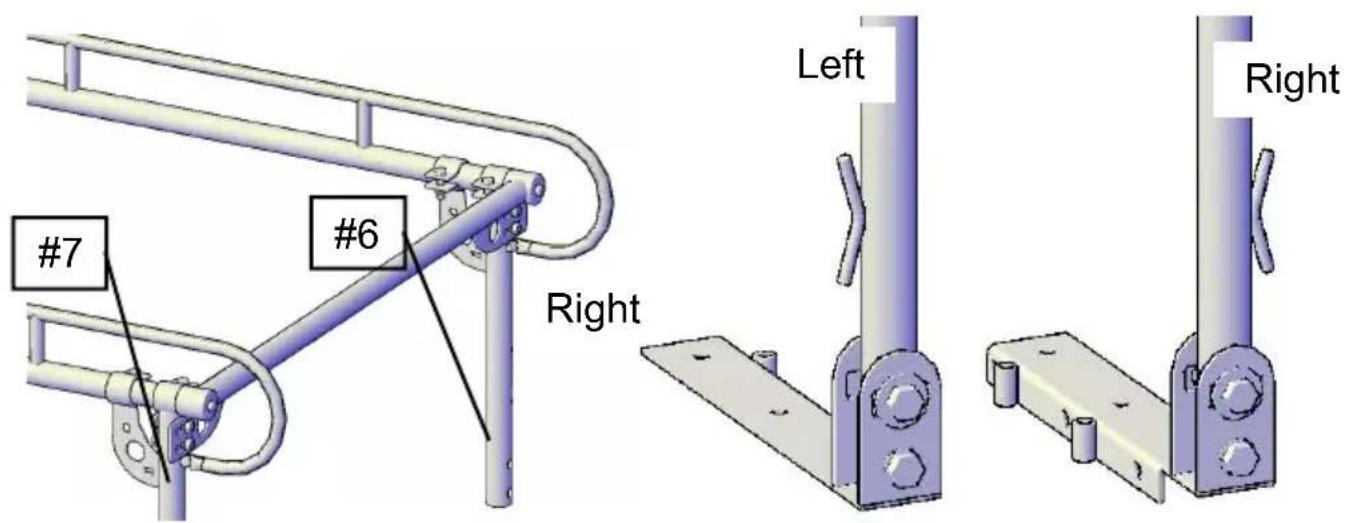
Fig.3 Fig.4
STEP 2: Install rear mounting feet
Attach the Left side rear mounting feet (#9) to the bottom of the Rear Left Stand.
Using one M18x90 bolt set. (Fig.4) Tighten snug, but not completely.
Repeat the same step for the rear right side.
(NOTE: The left side front and right side rear mounting feet is the same the right side front and left side rear)
You are now down assembling the rear section (Fig.5)
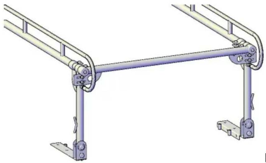
natural_image
Technical illustration of a mechanical linkage system with two vertical supports and a central horizontal beam (no text or symbols)Fig.5
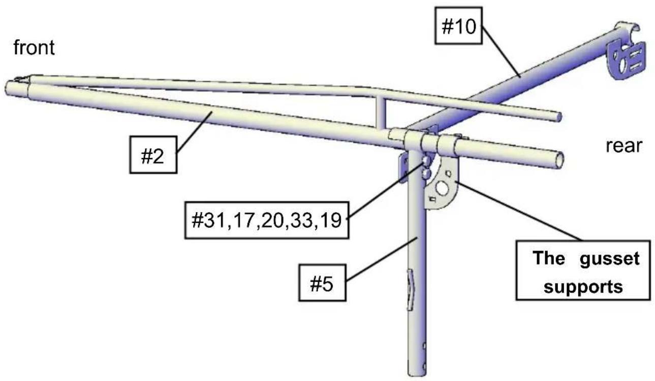
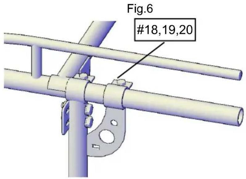
Fig.7

Fig.8
STEP 3:
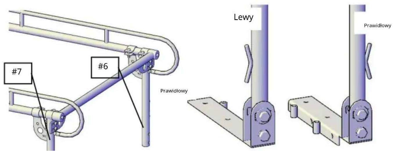
Slide the front side frames (#2) over the front left leg Stand (#5) .
(NOTE: The gusset supports on the front left leg Stand will be facing to the rear).
Attach using the 2-M12x70 bolts (#31), flat washer (17) (20), spring washer and Nut (19) (see the Accessory bolt set"G") Tighten snug but not completely (Fig.6)
Attach using the 2-M12x50 bolts(#18), flat washer(20) and Nut(19) (see the Accessory bolt set "B") Tighten snug but not completely. (Fig.7)
Repeat this for the opposite side using the front right leg Stand(#4). (Fig.8)
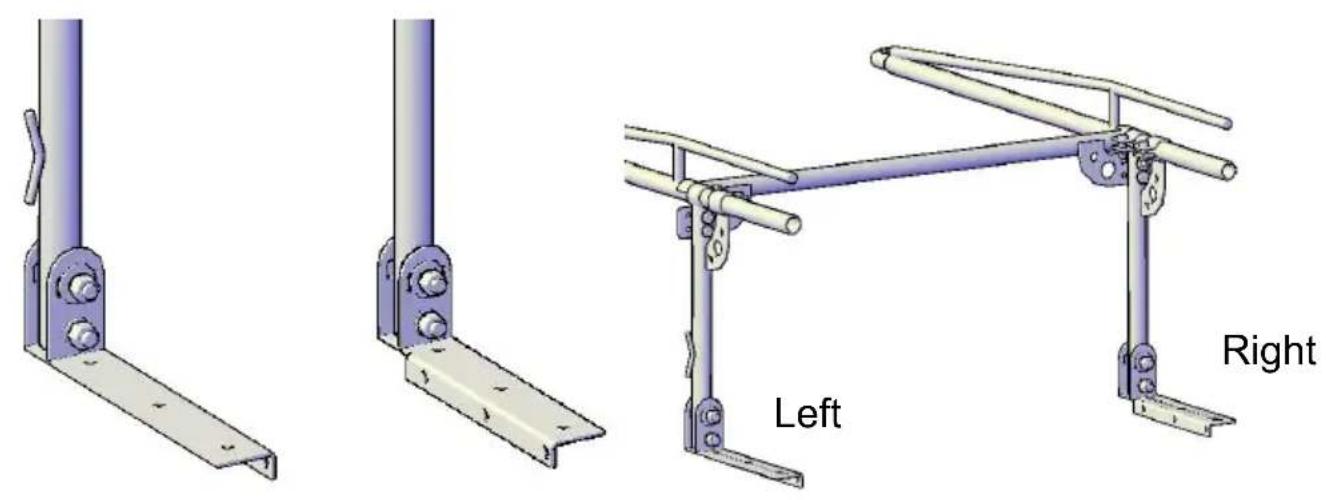
STEP 4: Install front mounting feet
Attach the Left side rear mounting feet (#8) to the bottom of the front Left Stand. Using one M18x90 bolt set. (Fig.9) Tighten snug, but not completely. Repeat the same step for the front right side.
natural_image
Technical illustration of three mechanical bracket assemblies labeled Left and Right, showing different mounting configurations (no text or symbols beyond labels)Fig.9
STEP 5:
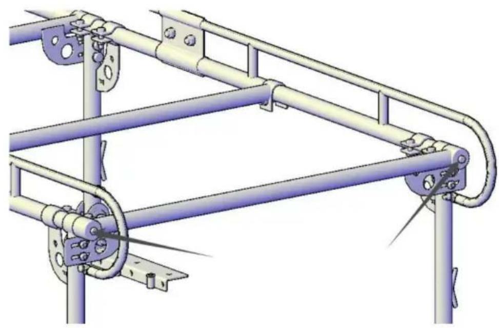
Slide the front section into the rear section. (NOTE: You may need assistant with this step).
Secure the two side frames together with Clamps(#13) and M16x30 bolts(#15) washer(#17) and nut(#16). You may tighten completely.
Repeat step for right side.(Fig 10,11)
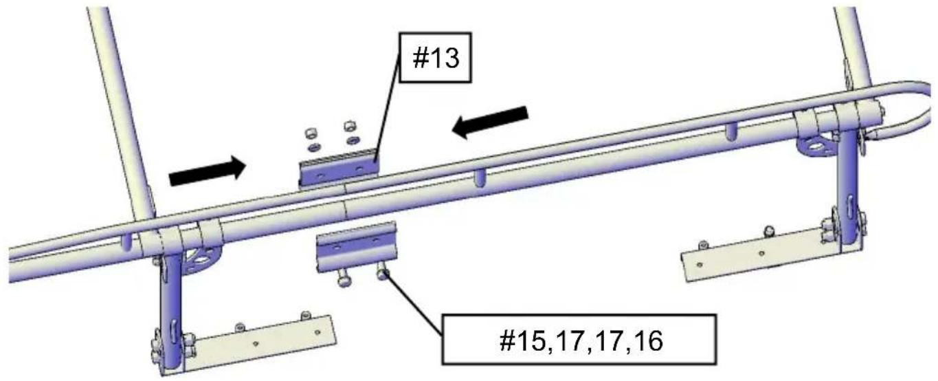
Fig.10
natural_image
Technical line drawing of a metal industrial rail system with support brackets and mounting feet (no text or symbols)Fig.11
STEP 6:
Install Center Bar(#11) to the rear frame using 2-M12x75 bolt sets (#24,19,20 (Fig 12) Tighten snug but not completely.
This bar can always be moved around.
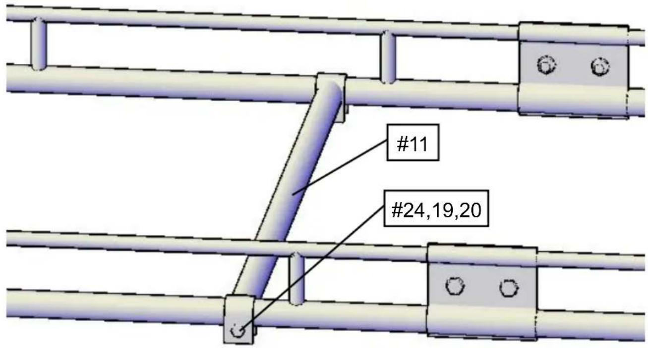
Fig.12
STEP 7:
Install the Cab bar(#1) to the front frame using M10x70 bolt sets (#35,22,37,) (Fig.13)
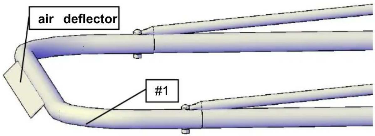
Fig.13
( Make sure the air deflector is pointing down.) You may tighten complete at this time.
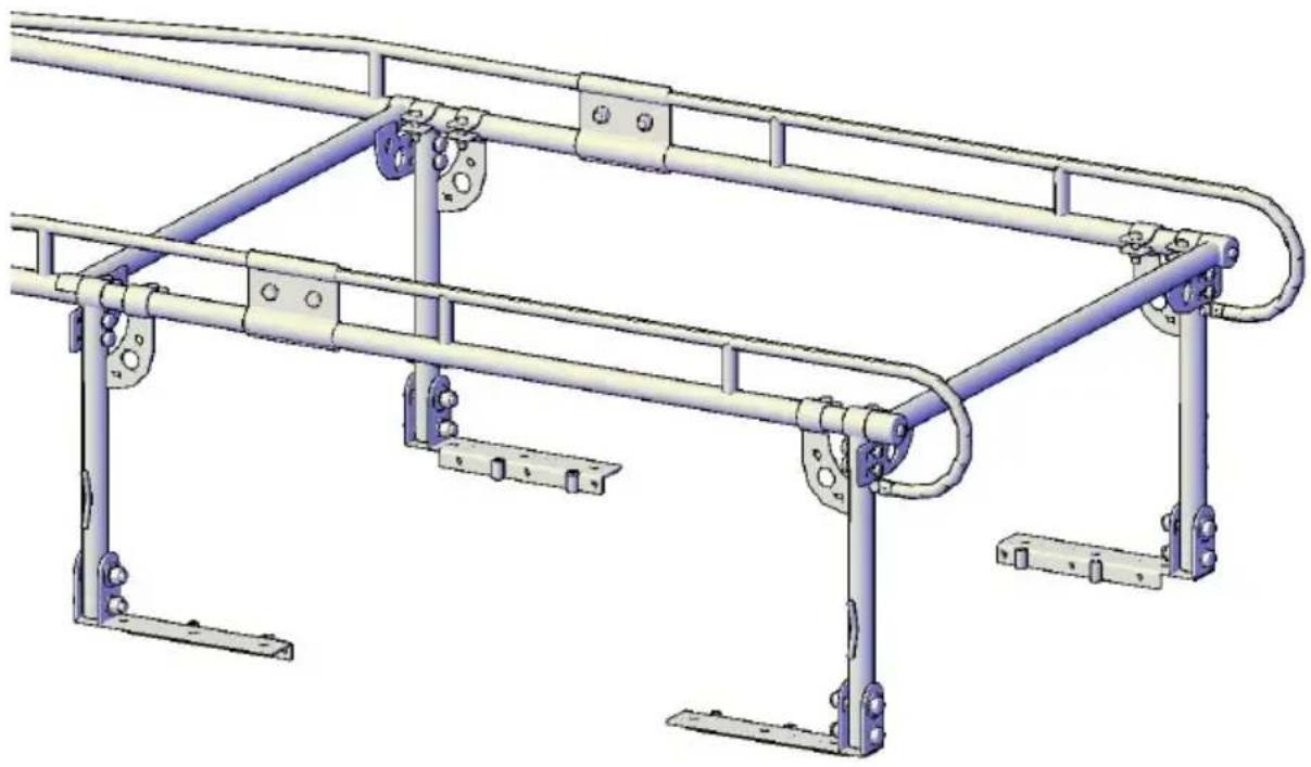
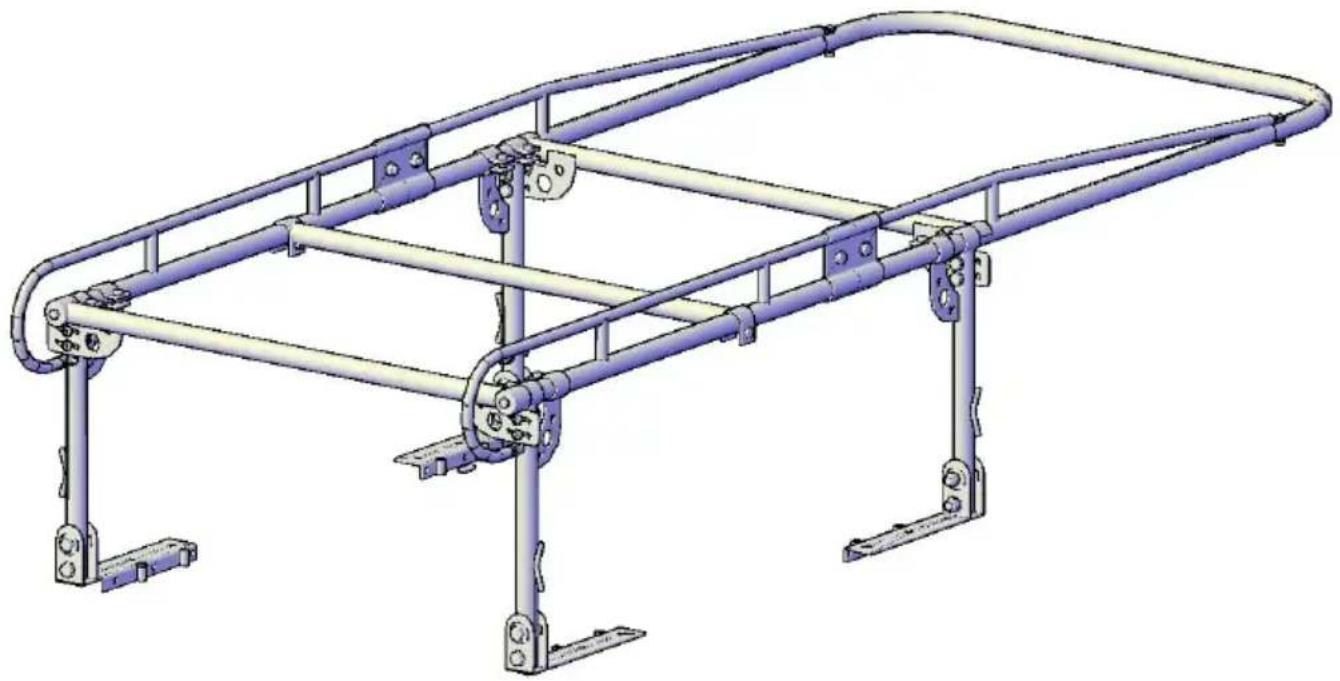
STEP 8:
General assembly is now complete. It is time to size the rack now.(Fig.14)
natural_image
3D CAD model of a metal frame structure with support legs and mounting brackets (no text or symbols)Fig.14
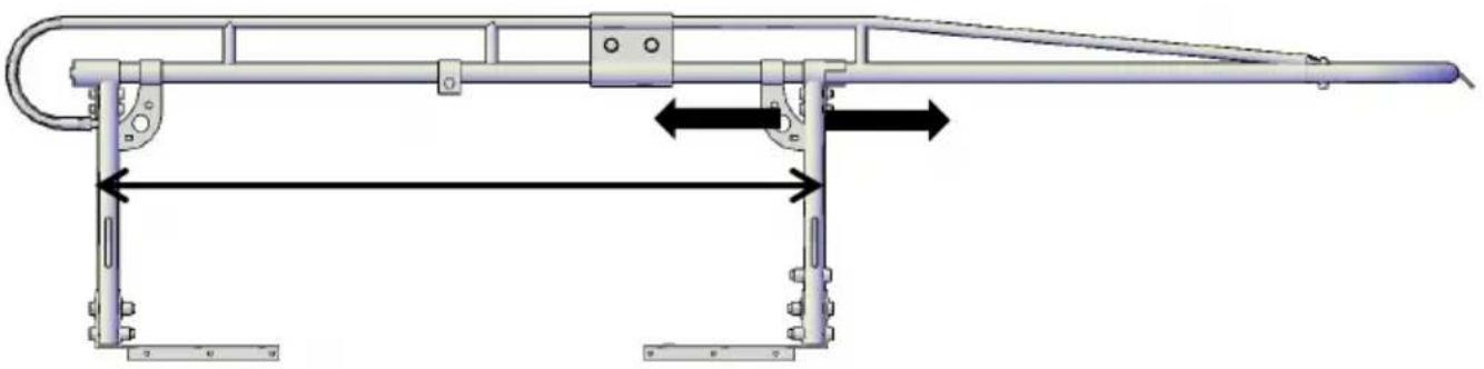
STEP 9:
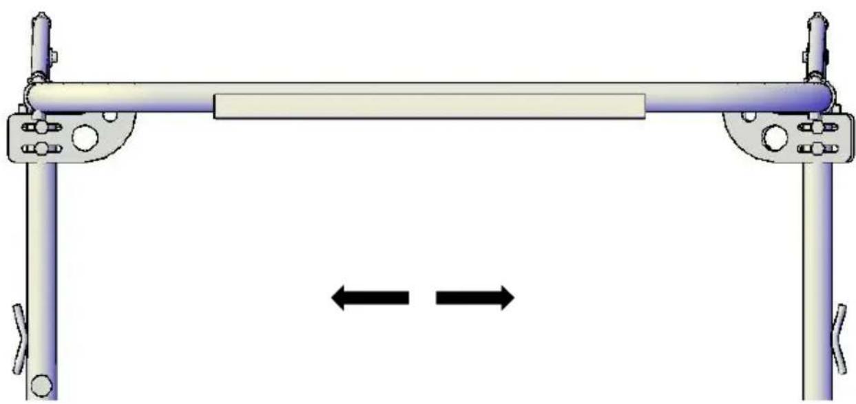
Measure the length of the top rail on your truck bed with the tailgate closed. Subtract 3-1/2" from this measurement, this gives you the approximate spacing needed between the front and rear leg Stands.
Adjust your front leg Stands by sliding them forward or backwards to match measurement.(Fig.15) Once position is correct tighten bolts snug, but not completely.
natural_image
Technical diagram of a mechanical lever system with bidirectional arrows indicating force or movement (no text or symbols present)Fig.15
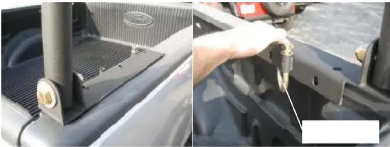
STEP 10:
Your rack is now ready to be installed on your vehicle.
Carefully lift the rack onto the side bed rails of your vehicle aligning the mc plates as close as possible to the corners of the bed rail. (Fig.16)
natural_image
Close-up of a Ford vehicle's roof panel and hand tool interacting with the engine compartment (no visible text or symbols)Fig.16 Fig.17
The leg Stands and mounting feet can be adjusted while the rack is resting vehicle bed rail.
STEP 11:
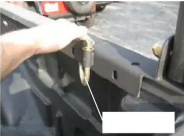
Once the desired location of the rack has been decided you can secure the mounting plates on the bed rail .This can be done two different ways, using Hooks(#39) or (2) bolting it down.
- Slide the "J" hook up through the sleeve in the mounting plate and secure washer and nut.
Make sure the plate on the end of the “J” hook is resting flush underneath rail. (Fig.17)
- Use the mounting feet as a template to mark and drill 17/32" holes through bed rail. Be sure to check underside for any obstructions. Measure the total thickness of the mounting foot and bed rail, select the M12 bolt of the appropriate length, and then lock the mounting foot and bed rail.
Secure mounting plates to bed rail completely at this time.
STEP 12:
Standing in front of the vehicle to check the horizontal alignment of the front in relation to the top of the vehicle. Have an assistant push or pull the race side in order to have the front hoop become parallel with the top of the ve (Fig.18)
natural_image
Mechanical lever diagram showing a horizontal beam supported at both ends with two vertical supports and a central roller, with bidirectional arrows indicating motion (no text or symbols)Fig.18

natural_image
Technical illustration of a metal scaffolding assembly with no visible text or symbolsFig.19
STEP 13:
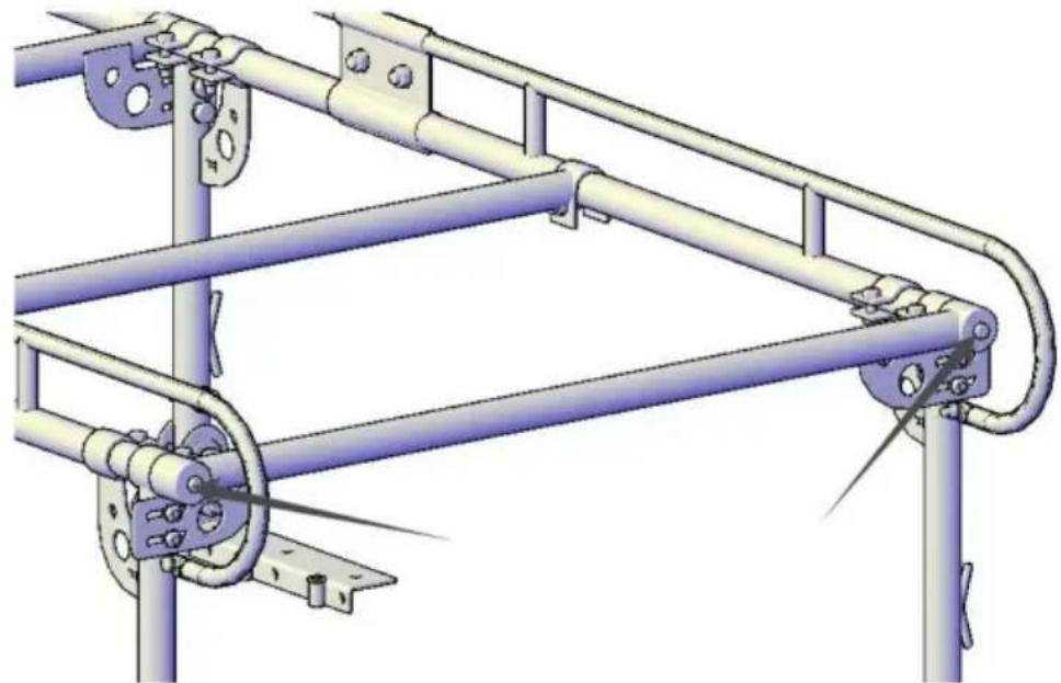
When you are satisfied with the alignment of the rack proceed to securely tie all four bolts that hold the legs to the mounting feet. (Fig.16) Now proceed securely tighten the two M12x50 bolts that hold the legs to the side frames. (Fig.2)
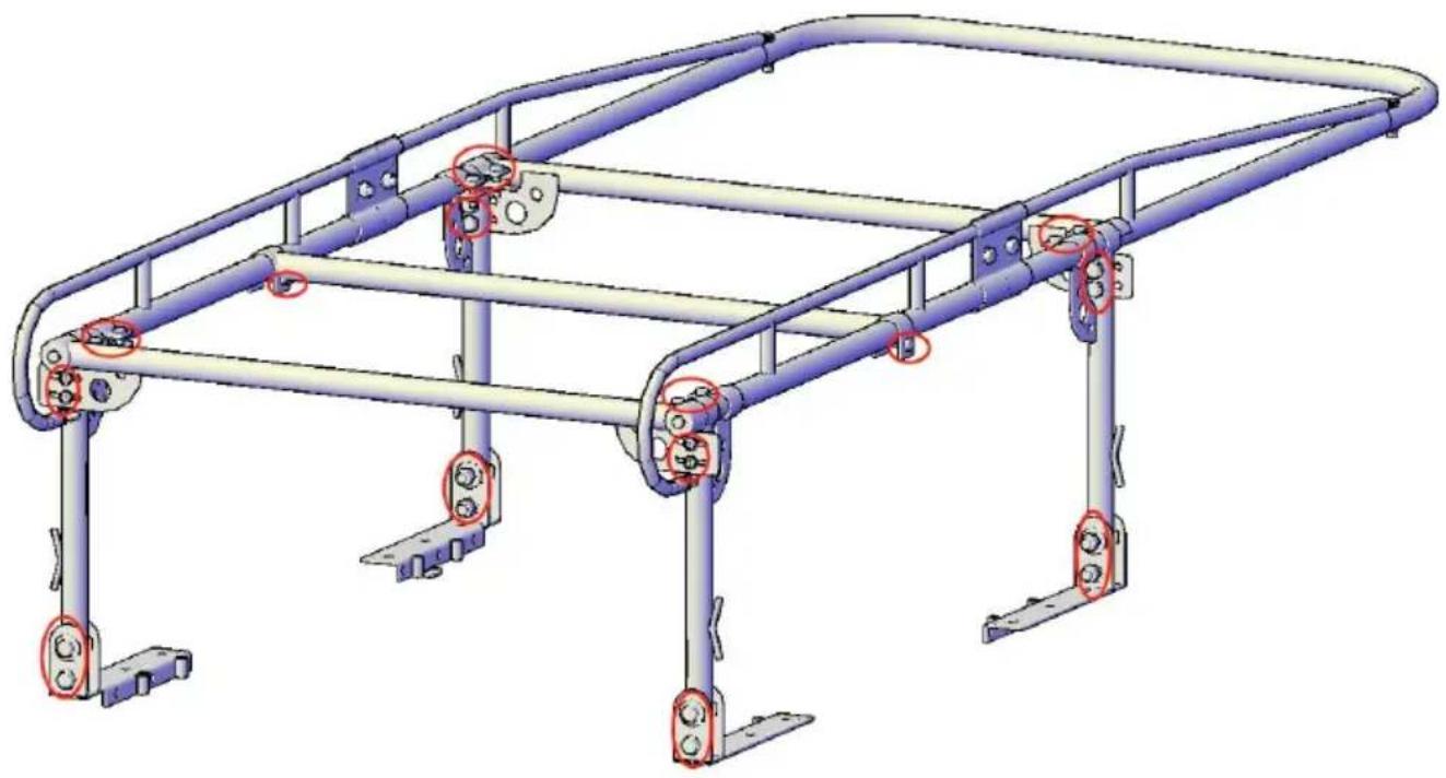
CHECK TO MAKE SURE ALL HARDWARE IS COMPLETELY TIGHT AT TH TIME. (Bolts as shown in Fig.20)
natural_image
3D technical illustration of a mechanical frame structure with no visible text or symbolsFig.20
INSTALLATION IS NOW COMPLETE
NOTE: In order to load tall items you may remove the rear cross bar k simply removing the bolt. (Fig.19) Be sure to re-attach the rear cross bar fasten after loading.
DO NOT CARRY LOAD WITHOUT REAR BAR
CLEANING
To keep your rack finish looking good, you can simply wash wit soft rag and mild soap
WARNING
Rollover and other types of vehicle accidents may result in serious injury or to you. your passengers and others sharing the road. VEVOR accessories are decorative and are not intended to reduce or avoid injury or damage in the an accident. the weight and location of VEVOR accessories may affect your vehicles handing, stability and performance, creating an increased risk of accident or rollover. Before installing any accessory, check state laws and assure that accessory will not obscure any lights or interfere with proper operation on your vehicle's safety equipment. Consult your owner's manual and the VEVOR instructions, or additional safety information. VEVOR products nor the warnings contained herein, are not a substitute for your safe driving. Don't drink and drink always use seat belts and don't drive faster than conditions permit.
VEVOR®
TOUGH TOOLS, HALF PRICE
Technical Support and E-Warranty Certificate
www.vevor.com/support
VEVOR®
TOUGH TOOLS, HALF PRICE
natural_image
Side view of a dark blue pickup truck with a metal roof rack and front livery (no visible text or symbols)BESOIN D'AIDE? CONTACTEZ-NOUS!
Figure 2Fig. 1
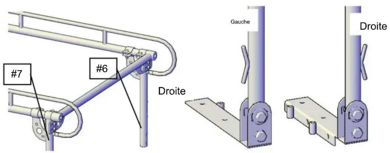
Figure 3
Figure 4
natural_image
Technical illustration of a mechanical linkage system with two vertical supports and a central horizontal beam (no text or symbols)Figure 5

Figure 6
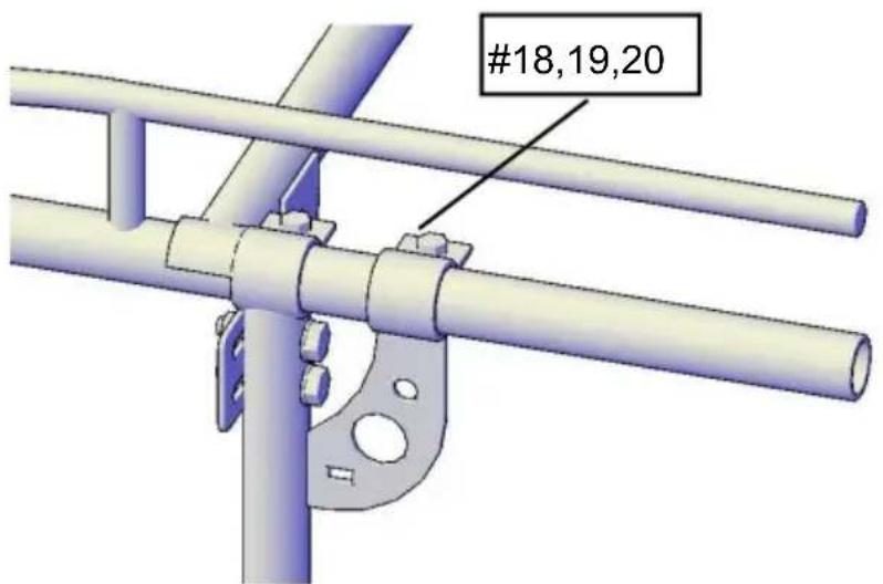
Figure 7
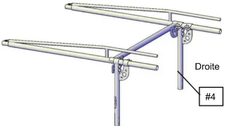
Figure 8
ÉTAPE 3:
Figure 9
ÉTAPE 5 :
natural_image
Technical line drawing of a metal structural frame with support brackets and mounting feet (no text or symbols)Figure 11
ÉTAPE 6 :
Figure 12
ÉTAPE 7 :
natural_image
3D rendering of a metal truss structure with support legs and mounting brackets (no text or symbols)Figure 14
ÉTAPE 9 :
natural_image
Technical diagram of a mechanical lever system with bidirectional arrows indicating force or movement (no text or labels)Figure 15
ÉTAPE 10 :
natural_image
Close-up of a car's roof panel and hand tool interacting with a component (no visible text or symbols)Figure 16 Figure 17
natural_image
Mechanical assembly diagram showing a lever with two vertical supports and a horizontal bar, with bidirectional arrows indicating motion (no text or symbols)Figure 18

natural_image
Technical illustration of a metal scaffolding assembly with railings and mounting brackets (no text or symbols)Figure 19
ÉTAPE 13 :
natural_image
3D technical illustration of a mechanical frame structure with no visible text or symbolsFigure 20
L'INSTALLATION EST MAINTENANT TERMINÉE
natural_image
Side view of a dark blue pickup truck with a metal roof rack and front livery (no visible text or symbols)Abb.1
Abb.2
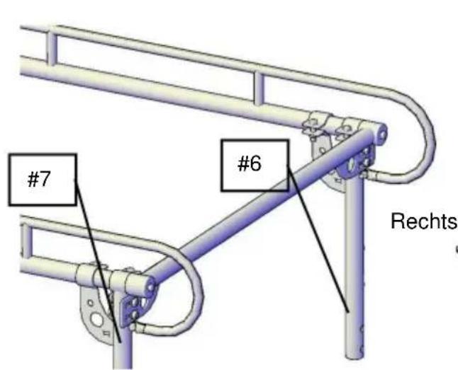
Abb. 3
Abb.4
natural_image
3D mechanical assembly diagram showing a bracket with a vertical rod and labeled 'Rechts' (no other text or symbols)natural_image
Technical line drawing of a metal frame structure with support brackets and mounting feet (no text or symbols)Abb.11
SCHRITT 6:
Abb.12
SCHRITT 7:
natural_image
3D rendering of a metal truss structure with support legs and mounting brackets (no text or symbols)Abb.14
SCHRITT 9:
natural_image
Technical diagram of a mechanical lever system with bidirectional arrows indicating force or movement (no text or labels present)Abb.15
SCHRITT 10:
natural_image
Mechanical assembly diagram showing a lever with two vertical supports and a horizontal bar, with bidirectional arrows indicating motion (no text or symbols)Abb.18

natural_image
Technical illustration of a metal scaffolding assembly with railings and mounting brackets (no text or symbols)Abb.19
SCHRITT
natural_image
3D technical illustration of a metal frame structure with multiple supports and mounting brackets (no text or symbols)Abb.20
DIE INSTALLATION IST JETZT ABGESCHLOSSEN
www.vevor.com/support
VEVOR®
TOUGH TOOLS, HALF PRICE
natural_image
Side view of a dark blue pickup truck with a metal roof rack and front livery (no visible text or symbols)HO BISOGNO DI AIUTO? CONTATTACI!
natural_image
Technical illustration of a mechanical linkage system with two vertical supports and a central horizontal beam (no text or symbols)Fig.5
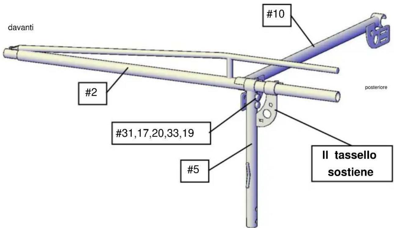
Fig.6

Fig.7

Fig.8
PASSO 3:
natural_image
Technical line drawing of a metal frame structure with support brackets and mounting feet (no text or symbols)Fig.11
PASSO 6:
Fig.12
PASSO 7:
natural_image
3D technical illustration of a metal frame structure with mounting brackets and support legs (no text or symbols)Fig.14
PASSO 9:
natural_image
Technical diagram of a mechanical linkage system with bidirectional arrows indicating force or movement (no text or symbols present)Fig.15
PASSO 10:
natural_image
Close-up of a car's roof and side panel showing a metallic guardrail and ventilation grille (no text or symbols visible)Fig.16

natural_image
Close-up of a hand adjusting a mechanical component with a tool, no visible text or symbolsFig.17
natural_image
Mechanical assembly diagram showing a lever with two vertical supports and a horizontal bar, with bidirectional arrows indicating motion (no text or symbols)Fig.18
natural_image
Technical illustration of a metal scaffolding assembly with railings and mounting brackets (no text or symbols)Fig.19
PASSO 13:
natural_image
3D technical illustration of a metal frame structure with mounting brackets and red circular annotations (no text or symbols)Fig.20
elettronica www.vevor.com/support
VEVOR®
TOUGH TOOLS, HALF PRICE
natural_image
Side view of a dark blue pickup truck with a metal roof rack and alloy railings (no visible text or symbols)Fig. 3
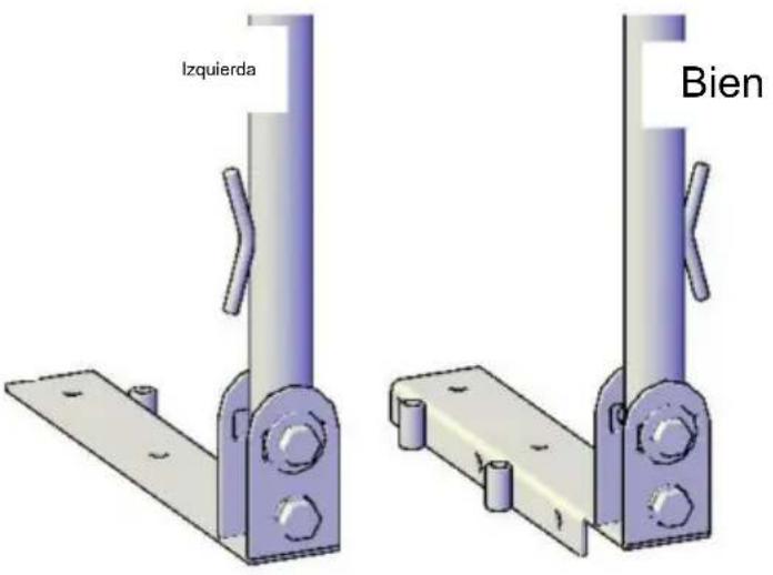
Fig.4
natural_image
Technical illustration of a mechanical linkage system with two vertical supports and a horizontal beam (no text or symbols)Fig.5
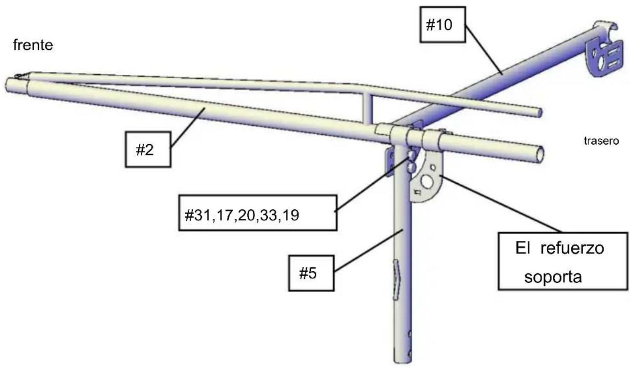
Fig.6
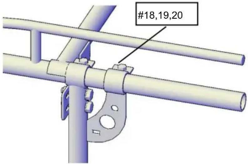
Fig.7
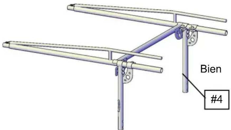
Fig.8
PASO 3:
natural_image
Technical illustration of three mechanical components with labeled parts, showing different mounting configurations (no text or symbols beyond labels)Fig.9
PASO 5:
natural_image
Technical line drawing of a metal frame structure with support brackets and mounting feet (no text or symbols)Fig.11
PASO 6:
Fig.12
PASO 7:
natural_image
3D CAD model of a metal truss structure with mounting brackets and support legs (no text or symbols)Fig.14
PASO 9:
natural_image
Technical diagram of a mechanical lever system with bidirectional arrows indicating force or movement (no text or labels present)Fig.15
PASO 10:
natural_image
Close-up of a car's roof panel and dashboard components, showing structural details and a hand adjusting a component (no visible text or symbols)Fig.16 Fig.17
natural_image
Mechanical assembly diagram showing a lever with two vertical supports and a horizontal bar, with bidirectional arrows indicating motion (no text or symbols)Fig.18
natural_image
Technical illustration of a metal scaffolding assembly with railings and mounting brackets (no text or symbols)Fig.19
PASO 13:
natural_image
3D technical illustration of a mechanical frame structure with no visible text or symbolsFig.20
natural_image
Side view of a dark blue pickup truck with a metal roof rack and front livery (no visible text or symbols)POTRZEBUJE POMOCY? SKONTAKTUJ SIĘ Z NAMI!
Ryc.2Ryc.1
natural_image
Technical line drawing of a metal frame structure with support brackets and mounting feet (no text or symbols)Ryc.11
KROK 6:
Ryc.12
KROK 7:
natural_image
3D CAD model of a metal frame structure with support legs and mounting brackets (no text or symbols)Ryc.14
KROK 9:
natural_image
Technical diagram of a mechanical lever system with bidirectional arrows indicating motion or force directions (no text or symbols present)Ryc.15
KROK 10:
natural_image
Close-up of a car's roof panel and hand holding a tool, showing mechanical components and wiring (no visible text or symbols)Ryc.16 Ryc.17
natural_image
Mechanical assembly diagram showing a lever with two vertical supports and a horizontal bar, with bidirectional arrows indicating motion (no text or symbols)Ryc.18

natural_image
Technical illustration of a metal scaffolding assembly with railings and mounting brackets (no text or symbols)Ryc.19
KROK 13:
natural_image
3D technical illustration of a metal frame structure with mounting brackets and red circular annotations (no text or symbols)Ryc.20
INSTALACJA JEST JUŻ ZAKOŃCZONA
www.vevor.com/support
VEVOR®
TOUGH TOOLS, HALF PRICE
Technische ondersteuning en e-garantiecertificaat www.vevor.com/support
VRACHTWAGENREK VOOR OVERCABINE
MODEL:SC1402
natural_image
Side view of a dark blue pickup truck with a metal roof rack and front livery (no visible text or symbols)HULP NODIG? NEEM CONTACT MET ONS OP!
Figuur 1
Fig. 2
Afb.4Afb.3
natural_image
Technical line drawing of a metal structural frame with support brackets and mounting feet (no text or symbols)Afb.11
STAP 6:
Afb.12
STAP 7:
natural_image
3D CAD model of a metal frame structure with support legs and mounting brackets (no text or symbols)Afb.14
STAP 9:
natural_image
Technical diagram of a mechanical linkage system with bidirectional arrows indicating force or movement (no text or symbols present)Afb.15
STAP 10:
natural_image
Close-up of a car's roof panel and hand holding a tool, both showing mechanical components (no visible text or symbols)Afb.16
Afb.17
natural_image
Mechanical assembly diagram showing a horizontal beam supported by two vertical posts, with bidirectional arrows indicating displacement (no text or symbols)Afb.18

natural_image
Technical illustration of a metal scaffolding assembly with railings and mounting brackets (no text or symbols)Afb.19
STAP 13:
natural_image
3D technical illustration of a mechanical frame structure with no visible text or symbolsAfb.20
DE INSTALLATIE IS NU VOLTOOID
garantiecertificaat www.vevor.com/support
VEVOR®
TOUGH TOOLS, HALF PRICE
natural_image
Side view of a dark blue pickup truck with a metal roof rack and front livery (no visible text or symbols)BEHÖVS HJÄLP? KONTAKTA OSS!
Fig. 7

Fig. 8
STEG 3:
natural_image
Technical line drawing of a metal frame structure with support brackets and mounting feet (no text or symbols)Fig. 11
STEG 6:
Installera Center Bar (#11) på den bakre ramen med 2-M12x75 bultsatser (#24,19,20).
Fig. 12
STEG 7:
natural_image
3D technical illustration of a metal frame structure with mounting brackets and support legs (no text or symbols)Fig. 14
STEG 9:
natural_image
Technical diagram of a mechanical lever system with bidirectional arrows indicating motion or force directions (no text or symbols present)Fig. 15
STEG 10:
natural_image
Close-up of a car's roof and side panel showing a metallic guardrail and ventilation grille (no text or symbols visible)Fig. 16
natural_image
Close-up of a hand adjusting a mechanical component with a tool, no visible text or symbolsFig. 17
natural_image
Mechanical assembly diagram showing a lever with two vertical supports and a horizontal bar, with bidirectional arrows indicating motion (no text or symbols)Fig. 18

natural_image
Technical illustration of a metal scaffolding assembly with railings and mounting brackets (no text or symbols)Fig. 19
STEG 13:
natural_image
3D technical illustration of a vehicle chassis frame with metal brackets and mounting hardware (no text or symbols)Fig.20
INSTALLATIONEN ÄR NU KLART
www.vevor.com/support


