PAC11 - Pool vacuum Vevor - Free user manual and instructions

Find the device manual for free PAC11 Vevor in PDF.
Vevor PAC11 - Pool vacuum
📄 160 pages English EN Download 💬 AI Question 10 questions ⚙️ Specs
Notice Vevor PAC11 - page 1
Pick your language and provide your email: we'll send you a specifically translated version.
Product type Suction pool cleaner
Brand Vevor
Model PAC11
Dimensions (L x W x H) 525 x 453,5 x 430 mm
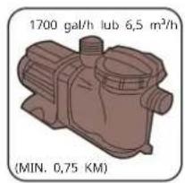
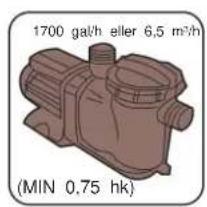
Required pump power ≥ 550 W (≥ 3/4 HP, flow 6.5 m³/h)
Maximum water flow 12 m³/h
Color Blue and white
Main functions Automatic cleaning of pool bottom and walls, debris suction
Assembly Detailed instructions provided, requires flat surface and basic tools
Routine maintenance Cleaning of pump and skimmer baskets, diaphragm replacement every 200 hours
Replaceable parts Diaphragm, pad, hoses, regulator, weight
Supplied accessories Hoses, regulator, weight, elbow fittings, skimmer adapter
Safety Do not sit or stand on the appliance, do not let children play, wear goggles and gloves during assembly
Troubleshooting Complete guide for common problems (immobility, slowness, jamming, etc.)
Technical support www.vevor.com/support
Warranty Electronic warranty certificate available online
Manufacturer Shanghaimuxinmuyeyouxiangongsi, Shanghai, China

Frequently Asked Questions - PAC11 Vevor

What to do if the cleaner does not move at start?
Check that the pump and skimmer baskets are clean and emptied. Clean the sand/cartridge filters. Make sure the cleaner head and the footrest outlet openings are not obstructed. Inspect the regulator valve for debris. If the pump power is too high, reduce the flow via the regulator by turning the knob in the « - » direction. Also check the condition of the diaphragm and the inner pole.
How to adjust the cleaner's power?
The power is adjusted by turning the regulator knob « I ». The « + » direction increases the flow, the « - » direction decreases it. Adjust gradually until optimal movement is achieved.
When and how to replace the diaphragm?
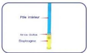
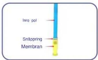
Replace the diaphragm every 200 hours of use or if it is clogged or damaged. To change it, unscrew the pole cover, remove the old diaphragm, then push the new one onto the inner pole, making sure the elastic ring is securely fastened.
Why is the cleaner slow?
This may be due to obstructions (baskets, filters, head, openings), a too low regulator setting (turn in the « + » direction), a worn or damaged diaphragm, or leaks in the hoses. Also check if the regulator is out of the water.
How to prevent the cleaner from getting stuck on steps?
Adjust the pool return jets toward the problematic area to guide the cleaner. Make sure the hose length is appropriate and the cleaner sits flat on the bottom. Adjust the position of the hose weight if needed, preferably in the deepest part.
What to do if the hose gets tangled?
Check that the wheel on top of the cleaner turns freely and is properly screwed. If the hose sections are twisted, lay the hose straight in the sun to relax the memory. Try removing a hose section if the length is excessive. Clean the regulator valve.
How to avoid air bubbles in return jets?
Make sure all hose connections are tight and the hose is not damaged. Check that the cleaner head remains submerged during operation and that the regulator valve is underwater.
How to adjust the hose weight?
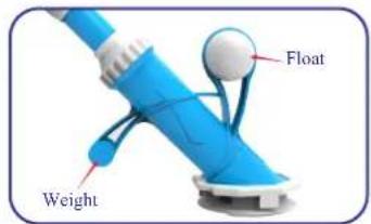
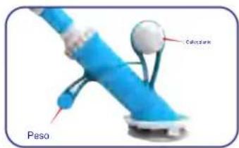
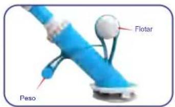
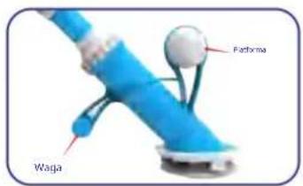
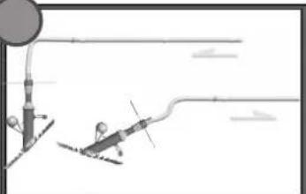
The « F » weight can be moved along the hose section to correct the cleaner's balance. If the cleaner leans too far forward or backward, move the weight in the opposite direction. Perform this adjustment in the deepest part of the pool.
What to do if the cleaner sticks to walls or bottom?
Make sure a valve is installed in the skimmer. Inspect and clean the regulator valve. Check the pad wear: a torn pad in some places is normal. Adjust the flow via the regulator by increasing or decreasing the power.
What pump power is needed for this cleaner?
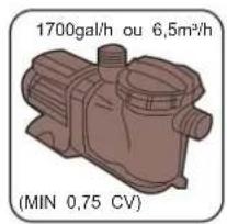
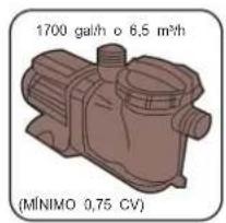
A pump of at least 550 W (3/4 HP, flow 6.5 m³/h) is required. The water flow must not exceed 12 m³/h. Insufficient or excessive power can impair operation.

User questions about PAC11 Vevor

0 question about this device. Answer the ones you know or ask your own.

Ask a new question about this device

Your email remains private: it is only used to notify you if someone answers your question.

No questions yet. Be the first to ask one.

Download the instructions for your Pool vacuum in PDF format for free! Find your manual PAC11 - Vevor and take your electronic device back in hand. On this page are published all the documents necessary for the use of your device. PAC11 by Vevor.

USER MANUAL PAC11 Vevor

Technical Support and E-Warranty Certificate www.vevor.com/support

SUCTION POOL CLEANER USER MANUAL

MODEL: PAC11

We continue to be committed to provide you tools with competitive price. "Save Half", "Half Price" or any other similar expressions used by us only represents an estimate of savings you might benefit from buying certain tools with us compared to the major top brands and does not necessarily mean to cover all categories of tools offered by us. You are kindly reminded to verify carefully when you are placing an order with us if you are actually Saving Half in comparison with the top major brands.

VEVOR®

TOUGH TOOLS, HALF PRICE

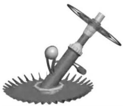
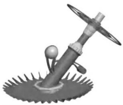
SUCTION POOL CLEANER

MODEL: PAC11
3D rendered mechanical component with spoked base and central hub (no text or symbols)

NEED HELP? CONTACT US!

Have product questions? Need technical support? Please feel free to contact us:

Technical Support and E-Warranty Certificate

www.vevor.com/support

This is the original instruction, please read all manual instructions carefully before operating. VEVOR reserves a clear interpretation of our user manual. The appearance of the product shall be subject to the product you received. Please forgive us that we won't inform you again if there are any technology or software updates on our product.

SAFETY INSTRUCTIONS

WARNING:

Read this material before using this product. Failure to do so may result in serious injury.

Assembly precautions

  1. Assemble only according to these instructions. Improper assembly may create hazards.
  2. Wear ANSI-approved safety goggles and heavy-duty work gloves during assembly.
  3. Keep the assembly area clean and well-lit.
  4. Keep bystanders out of the area during assembly.
  5. Do not assemble if tired or when under the influence of alcohol, drugs or medication.
  6. The product capabilities apply to properly and completely assembled products only.
  7. Assemble on a flat, level, hard and smooth surface capable of safely supporting the Suction Pool Cleaner.
  8. For additional information regarding the parts listed in the following pages, please refer to the Assembly Diagram of this manual. Unwrap and separate all parts in a clean work area.

Use precautions

  1. DO NOT SIT OR STAND ON THIS ITEM.
  2. This product is not a toy. Do not allow children to play with or near this item.
  3. Do not exceed specified weight capacities.
  4. Use only on a flat, level, hard, and smooth surface that can safely support a fully loaded Suction Pool Cleaner.
  5. Use as intended only.
  6. Inspect before every use; do not use if parts are loose or damaged.

SAVE THIS MANUAL

PARTS LIST
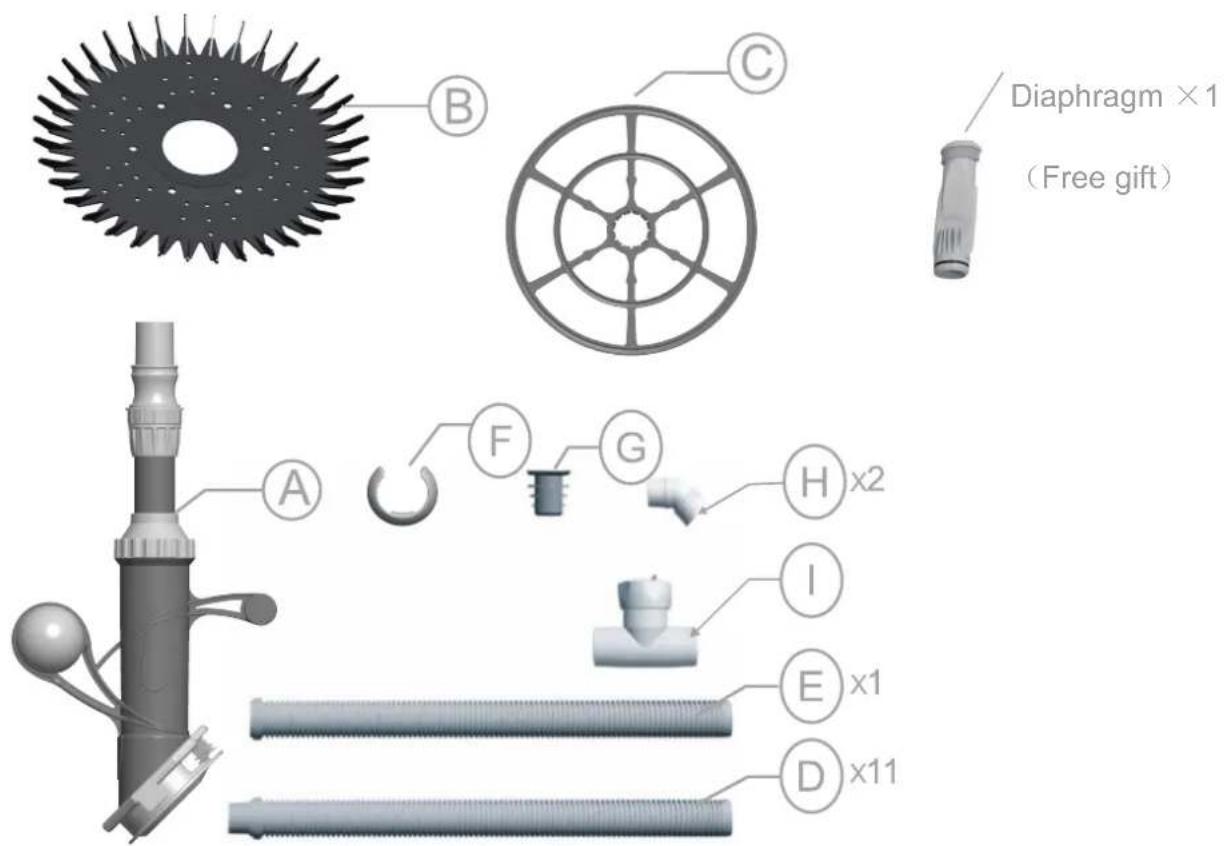
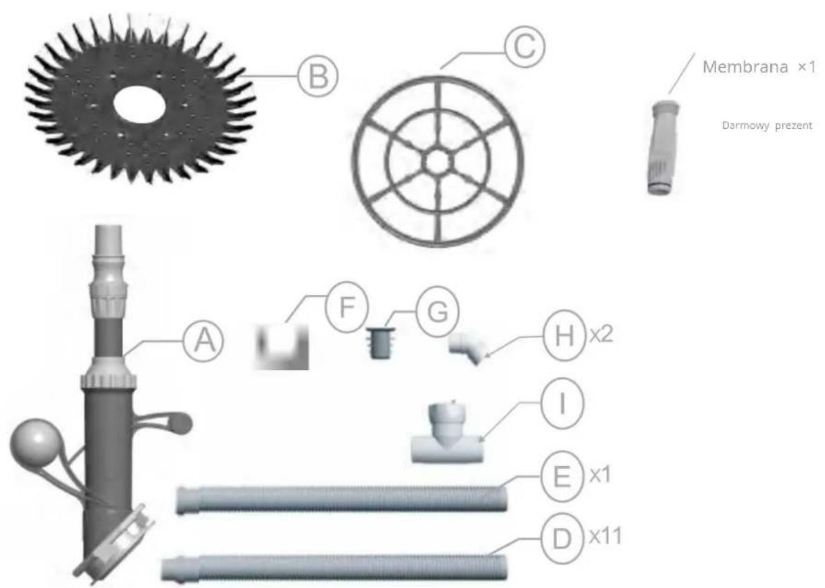
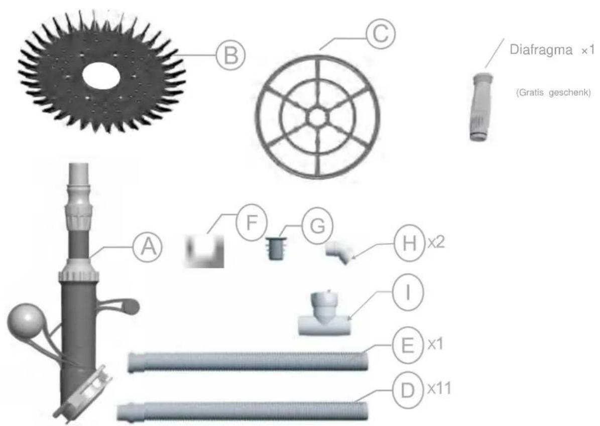
Diaphragm ×1 (Free gift) A B C F G H x2 I E x1 D x11

ASSEMBLY STEP

Guidelines for replacing diaphragm

QR code image containing encoded data, no visible human-readable text

Assemble the suction pool cleaner's head

QR code image containing encoded data, no visible human-readable text

Assembly steps of suction pool cleaner

QR code image containing encoded data, no visible human-readable text

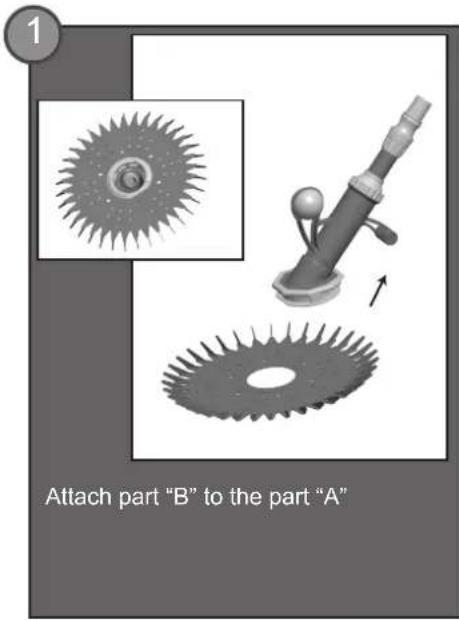
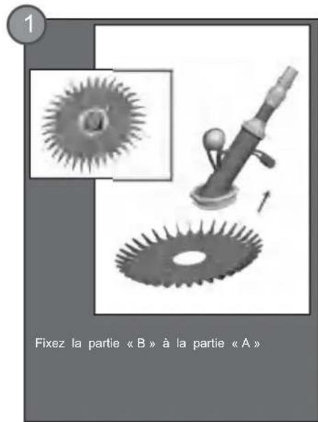
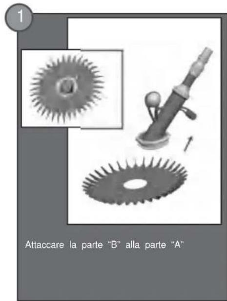
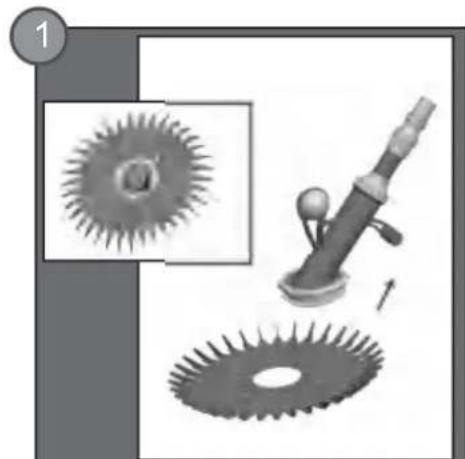
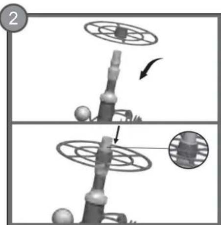
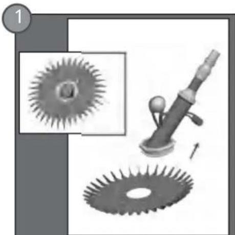
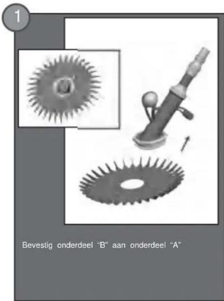
1. Attach part "B" to part "A".

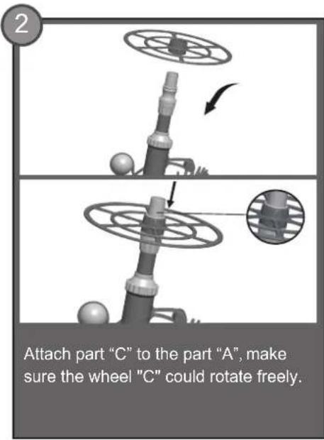
2. Attach part "C" to part "A", making sure wheel "C" can rotate freely.

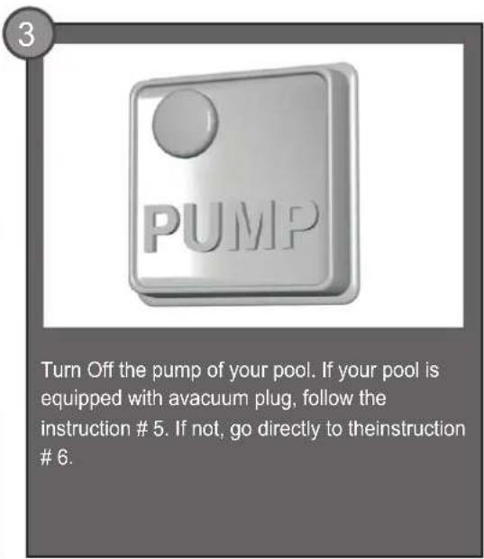
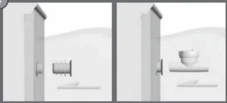
3. PUMP: Turn off the pump of your pool. If your pool is equipped with a vacuum plug, follow instruction #5. If not, go directly to instruction #6.

4Exterior view of a modern office building (no signage)

Minimalist illustration of a wall-mounted device next to a cylindrical component (no text or symbols visible)

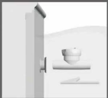
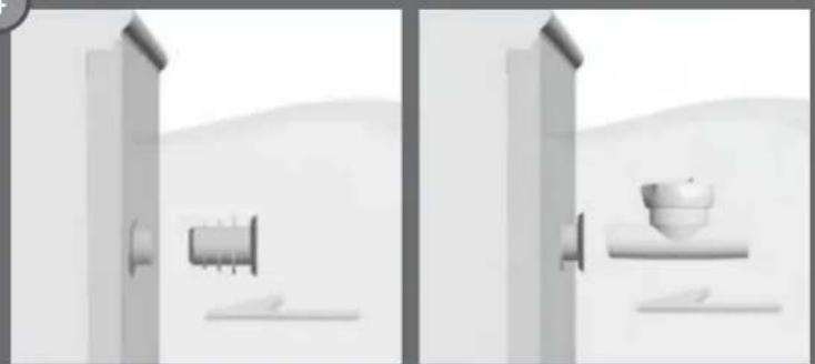
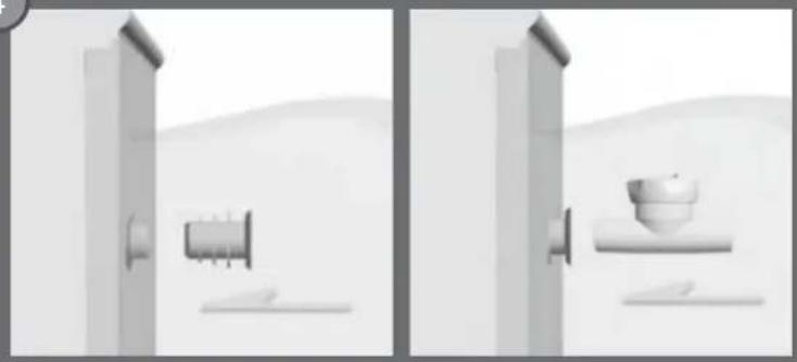
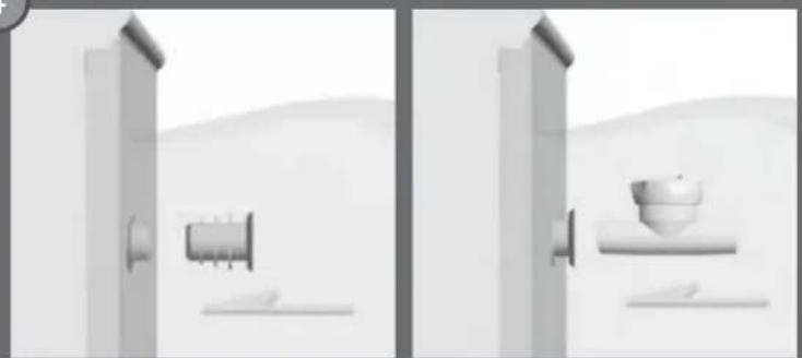
Connect the part "G" into your Vac plug. Connect the regulator "I" into the part "G". Make sure that the arrow under the regulator is pointed towards the vac plug. GO now directly to the instruction # 8.

5Close-up of a white plastic door with a circular vent and a rectangular slot (no text or symbols visible)
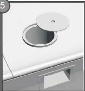
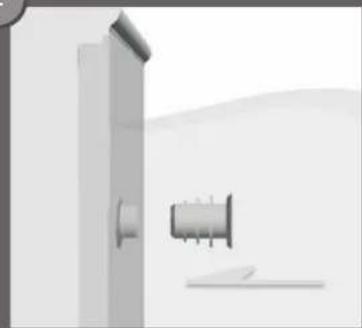
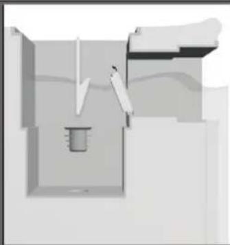
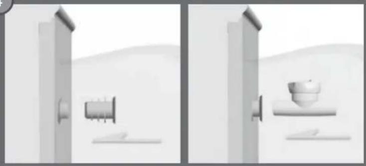
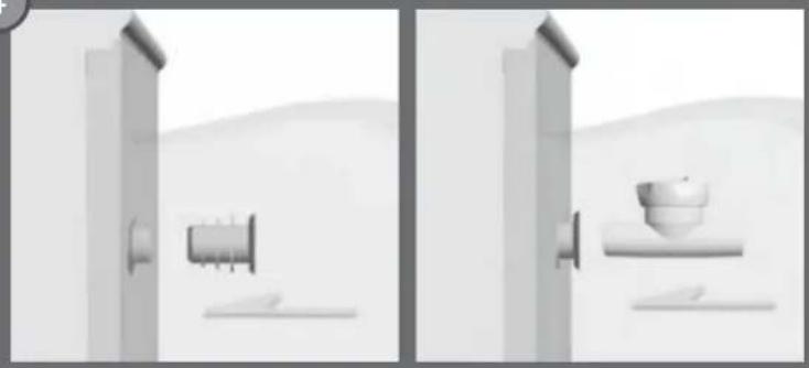
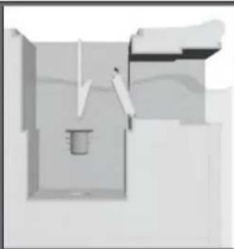
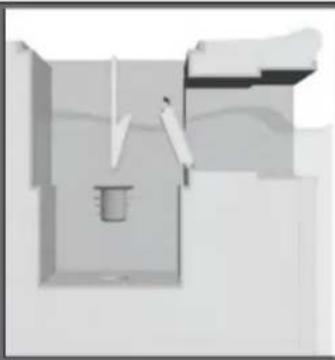
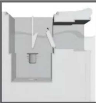
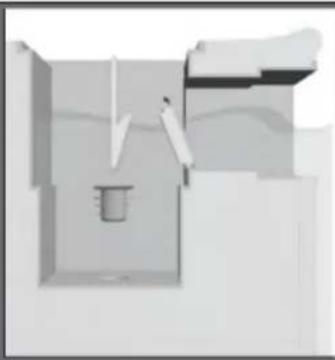
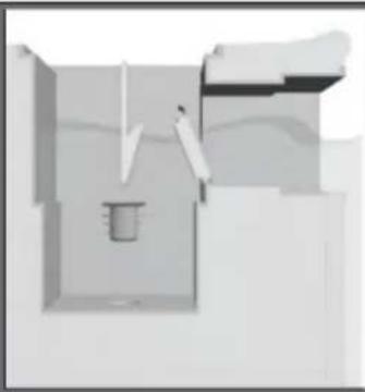
Remove the top lid and the basket of your wall skimmer.

63D rendered diagram of a pipe fitting with a hexagonal bolt and flange (no text or symbols)
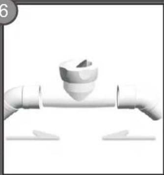
Pure architectural floor plan lines without any text, numbers, or symbols

Diagram of a pipe outlet with a valve, showing internal flow and support structure (no text or labels)

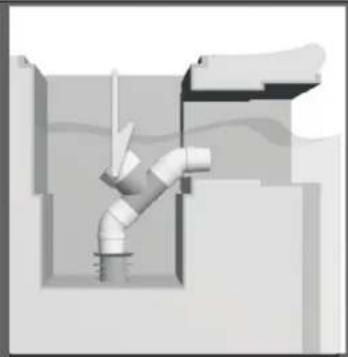
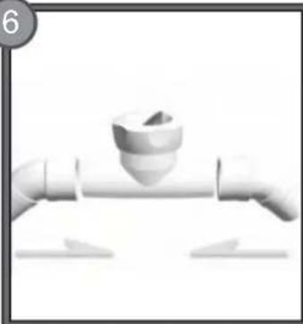
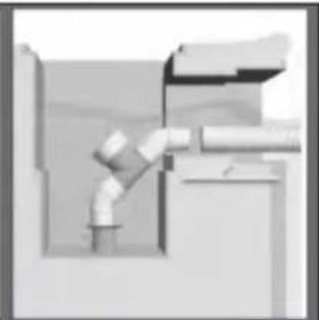
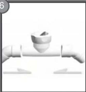
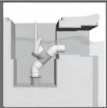
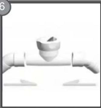
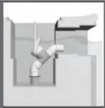
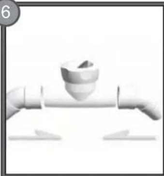
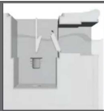
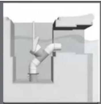
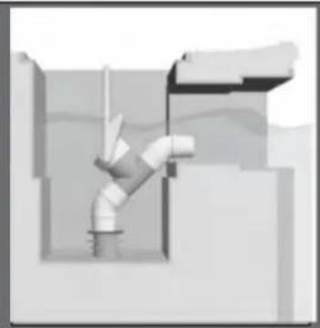
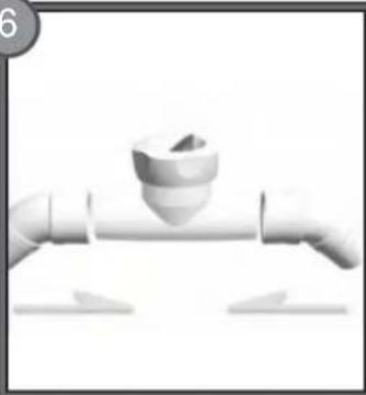
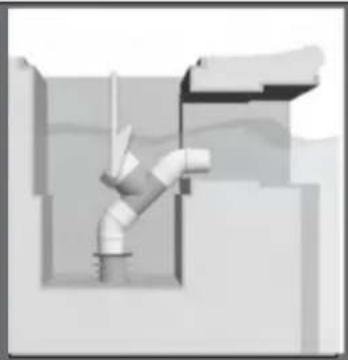
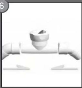
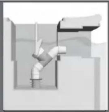
Assemble the two elbow connectors "H" to the regulator "I". Insert the attachment "G" facing downward and then the regulator. Make sure that the arrow under the regulator is pointing towards the skimmer.

7Two threaded mechanical components with a downward arrow indicating compression or dislocation (no text or symbols)
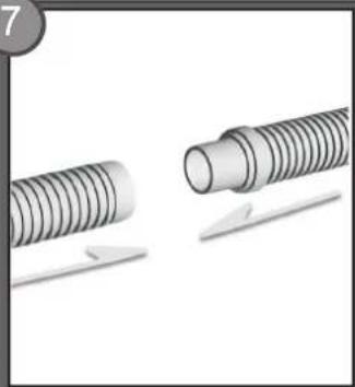
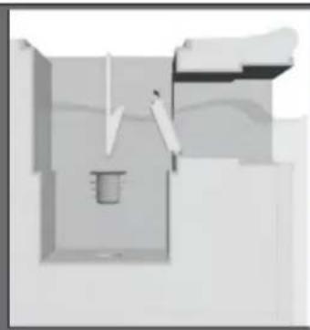
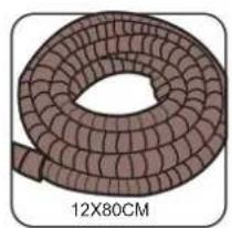
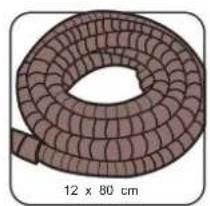
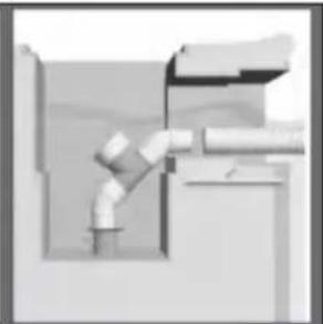
Connect together the tube sections "D" and finish by section "E".

8Technical illustration of a mechanical device with a curved component and a separate inset showing its cross-section (no text or symbols)
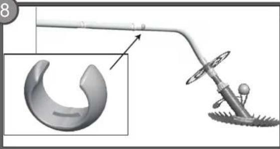
Place the weight "F" at the end of the first tube section, and connect the tube assembly to the cleaner.

9 10Close-up of a finger pointing at a textured surface with small droplets (no text or symbols visible)
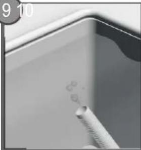
Fill the tube sections with water to eliminate the air pockets.
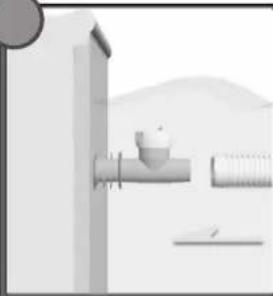
Illustration of a wall-mounted tool next to a cylindrical component, with a mountainous background (no text or symbols)

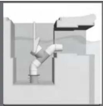
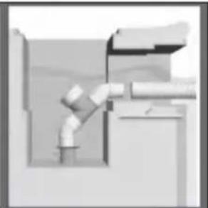
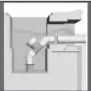
If your regulator is connected to a wall skimmer, pass the hose through the front of your skimmer and connect it to the elbow connector.
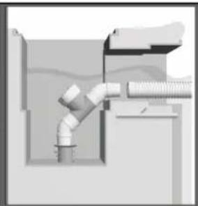
Diagram of a pipe connection with a coiled hose and pipe fitting (no text or labels)

11Illustration of a gasifier or scrubber system with pipes, valves, and a central tank (no text or symbols visible)

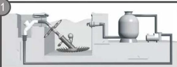
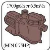
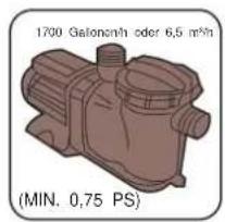
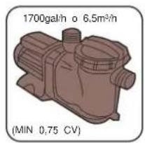
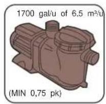
Adjust your filtration system to the vacuum setting. A pump of at least 3/4 horsepower (6.5 m^3/h) is required. Water flow should not be larger than 12 m^3/h.

12PUMP
Turn on the pump and relax as your cleaner cleans your pool.

13Abstract grayscale illustration of a stylized eye-like shape with circular elements (no text or symbols)
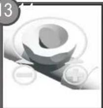
You can adjust the power of your cleaner by turning the knob of the regulator "I" as shown.
Simple line drawing of a pipeline system with two workers and pipes (no text or symbols)

If the cleaner leans too far forward or backwards during operation, this can be corrected by moving the weight "F" along the tube section as shown in the drawing.

DIAPHRAGM ASSEMBLY

1Illustration of a hand using a tool to lift a block, with motion arrows indicating rotation (no text or symbols)
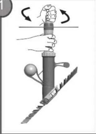
STEP1:

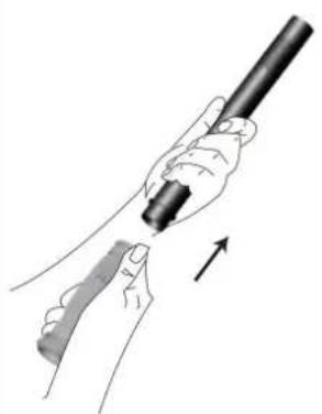
Unscrew the cover pole with the wheel from the body.

2Mechanical gear assembly diagram showing teeth and shaft (no text or labels)
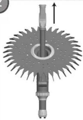
STEP2:

Pull the diaphragm and inner pole from the body.

3Illustration of a hand holding a pen and a tool, with an arrow indicating direction (no text or symbols present)
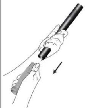
STEP3:

Pull the diaphragm from the inner pole.

4Illustration of a hand holding a pen and a tool, with an arrow indicating direction (no text or symbols)
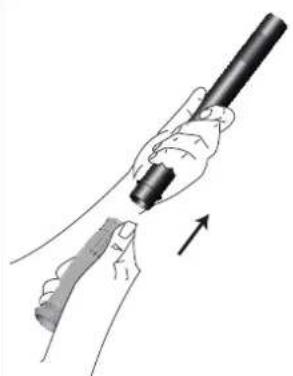
STEP4:

Then push the new diaphragm onto the inner pole.
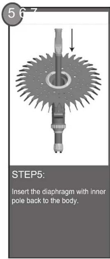
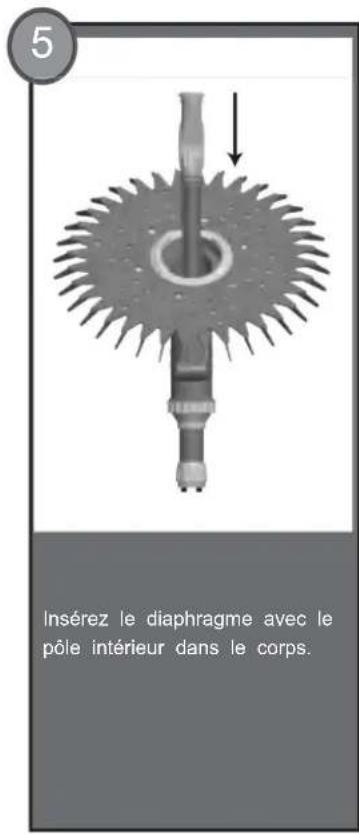
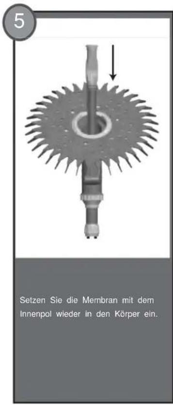
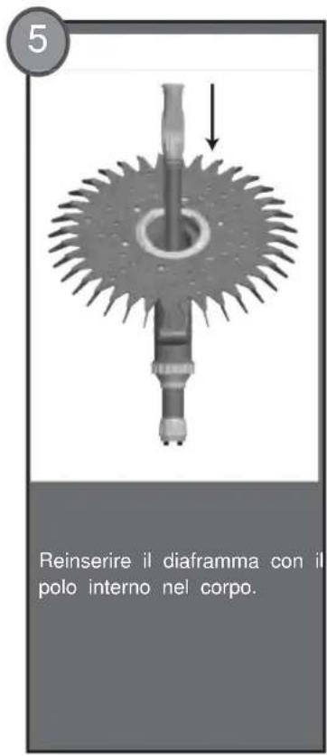
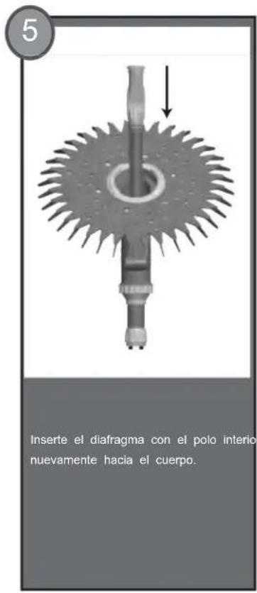
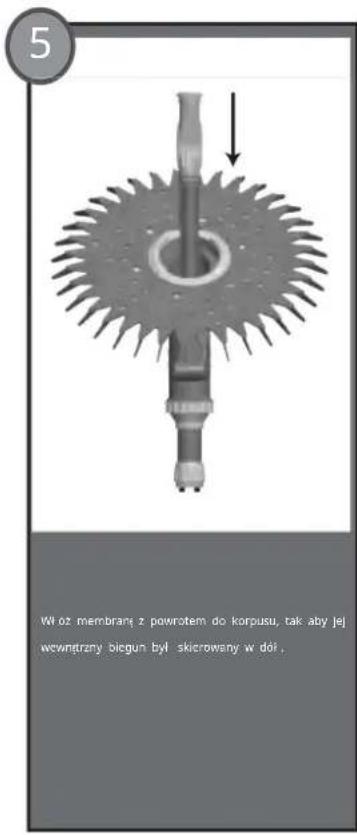
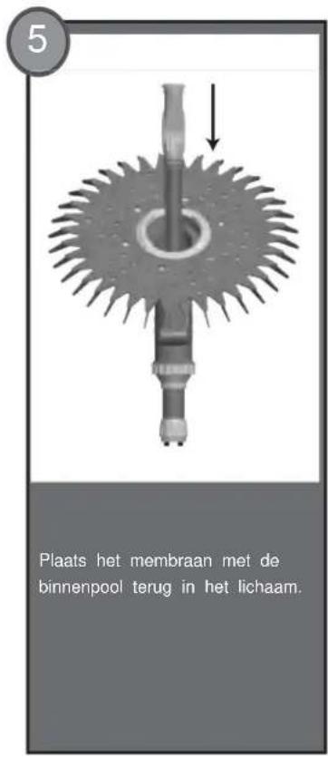
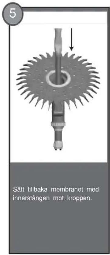
567 STEP5: Insert the diaphragm with inner pole back to the body.

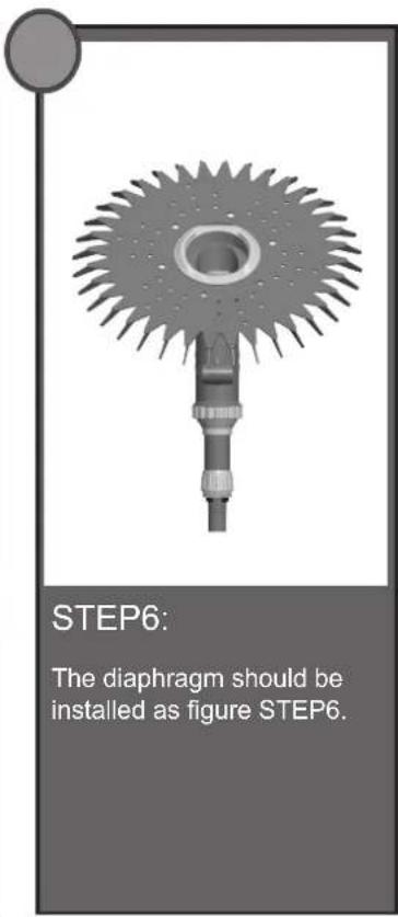
STEP6: The diaphragm should be installed as shown in figure STEP6.

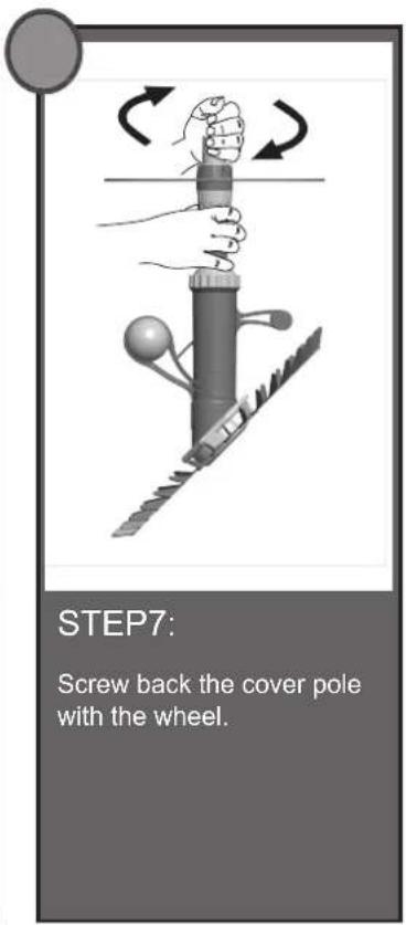
STEP7: Screw back the cover pole with the wheel.

NOTE: Please replace the diaphragm in a timely manner when used for 200 hours.

TROUBLESHOOTING

1. Problem: Cleaner doesn't move at the very beginning but the hoses are trembling.

Solution:

  • Clean and empty the pump basket and the empty skimmer/weir basket.
  • Ensure the filtration system is thoroughly cleaned. Clean sand/cartridge filters on your pool pump as per manufacturer specifications.

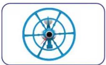
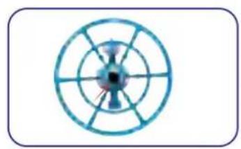
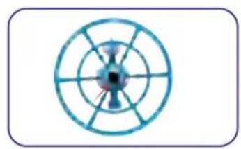
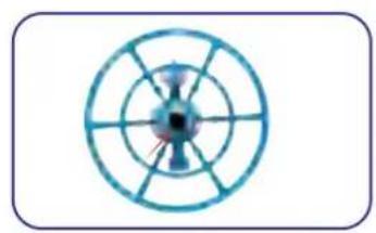
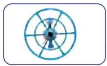
- Check the Cleaner head for blockages. (See Figure 1)

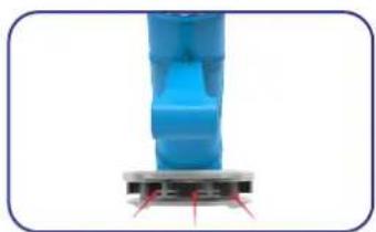
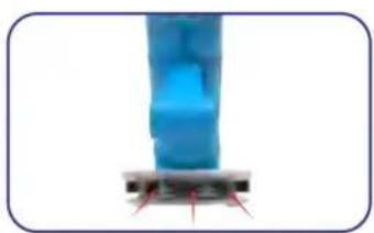
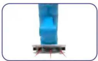
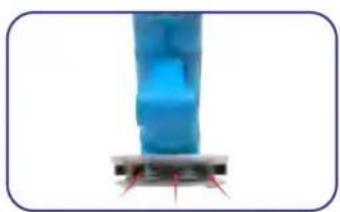
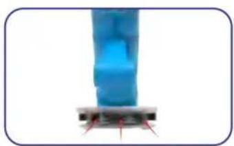
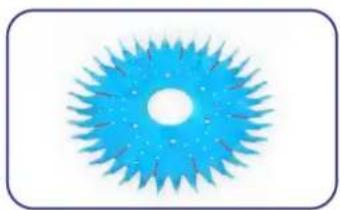
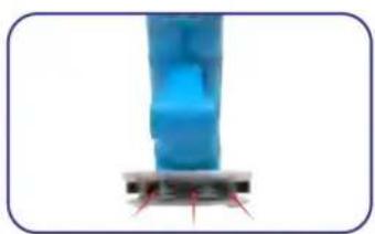
- Check the outlet holes on foot pad for blockages. (See Figure 2)

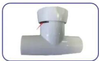
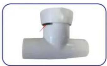
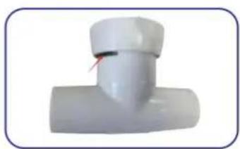
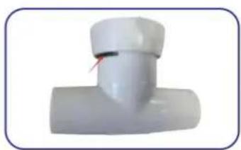
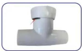
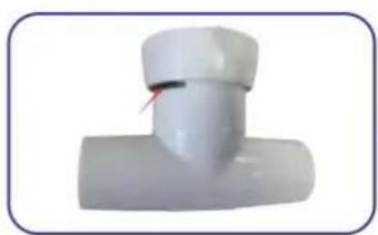
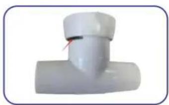
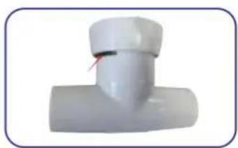
- Inspect the regulator valve and flush away any debris build-up. (See Figure 3)

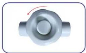
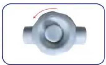
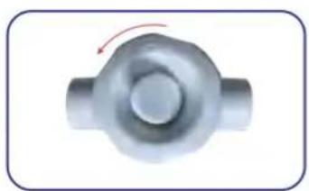
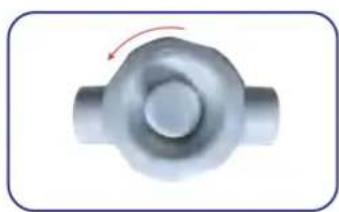
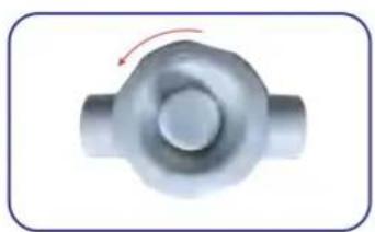
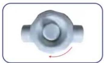
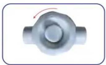
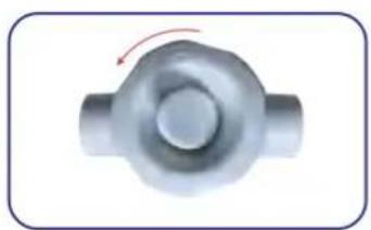
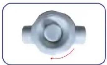
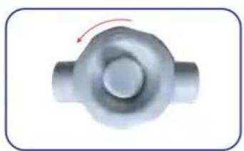
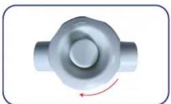
- Check if the pump power is too big; try decreasing the flow to your cleaner via the regulator, and adjust the regulator by turning the knob to the "-" direction slowly until the cleaner runs well. (See Figure 4a)

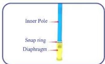
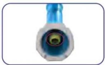
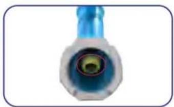
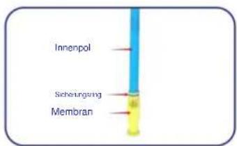
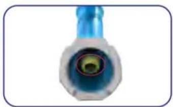
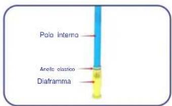
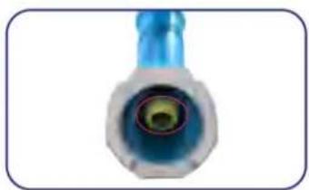
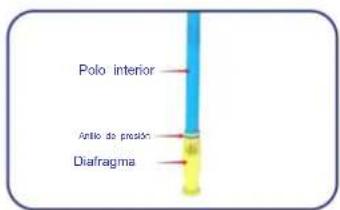
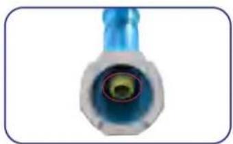
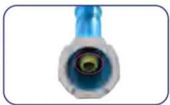
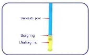
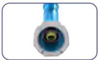
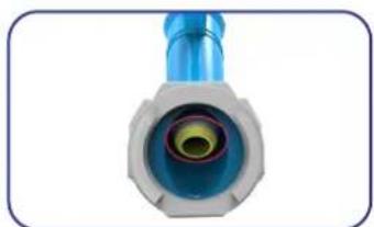
- Check the cleaner diaphragm is not blocked or damaged, or loosened from the inner pole, or the inner pole is damaged. (See Figure 5 and Figure 6) Please note that the snap ring should be fixed on the diaphragm. If you need to check the diaphragm and inner pole status, please check the DIAPHRAGM ASSEMBLY process in the instruction to disassemble this part from the body.

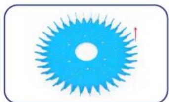
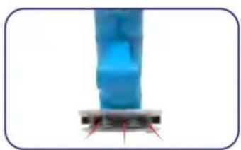
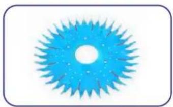
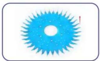
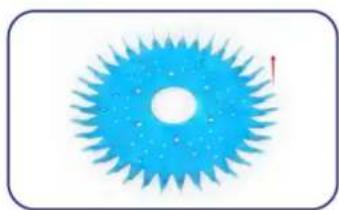
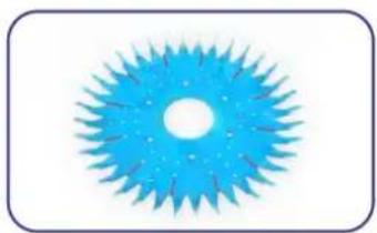
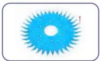
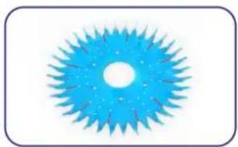
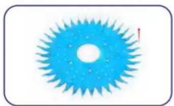
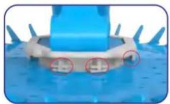
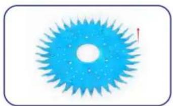
- Make sure the curved tips of the Mat are facing upwards. You will find "TOP" on the top side. (See Figure 7)

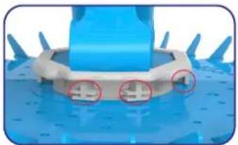
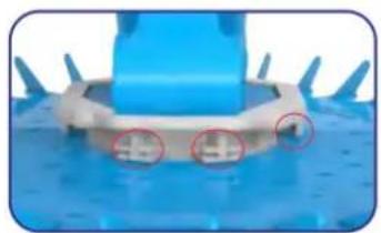
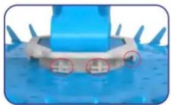
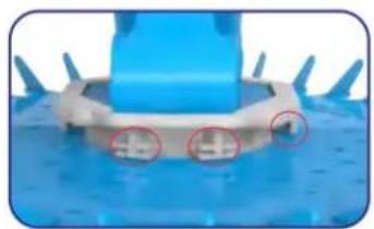
- Make sure the mat is assembled in right place on foot pad as picture show and can move freely around the foot pad. (See Figure 8)

- Check if the hoses are blockage or leaking. For leaking you could check with your hand on the surface of the hoses in the water while the pump is running; you will feel suction when your hand is on the leaking surface.

- Check if the pump has air inside and causes less suction power.

- Consult a pool shop in your area.

2. Problem: Cleaner is sluggish.

Solution:

  • Clean and empty the pump basket and the skimmer/weir basket.
  • Ensure the filtration system is thoroughly cleaned. Clean sand/cartridge filters on your pool pump as per manufacturer specifications.
  • Check the Cleaner head for blockages. (See Figure 1)
  • Check the outlet holes on the foot pad for blockages. (See Figure 2)
  • Inspect the regulator valve and flush away any debris build-up. (See Figure 3)
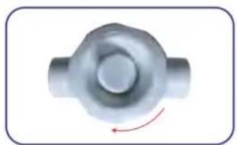
  • Check if the regulator knob is turning to the "-" direction too much, causing less power to the cleaner. Turn to the "+" direction until the cleaner runs well. (See Figure 4b)
  • Check if the regulator is out of water with air running inside.
  • Check the cleaner diaphragm is not blocked or damaged, loosened from the inner pole, or the inner pole is damaged. (See Figure 5 and Figure 6) Please note that the snap ring should be fixed on the diaphragm. If you need to check the diaphragm and the inner pole status, please check the DIAPHRAGM ASSEMBLY process in the instruction to disassemble this part from the body.
  • Check if the diaphragm reaches its lifespan. Change the diaphragm.
  • Make sure the mat is assembled in the right place on the foot pad, as the picture shows and can move freely around the foot pad. (See Figure 8)
  • Check if the hoses are blocked or leaking. For leaking, you could check with your hand on the surface of the hoses in the water while the pump is running, you will feel suction when your hand is on the leaking surface.
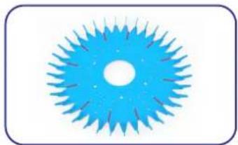
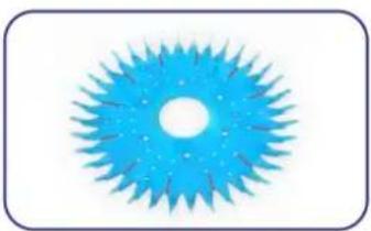
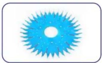
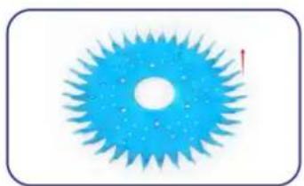
  • Check the mat for wear. Please note that if the mat is torn in these positions, operating is okay. (See Figure 9)
  • Check if the pump has air inside and causes less suction power.
  • Consult a pool shop in your area.

3. Problem: Cleaner gets stuck on steps.

Solution:

  • Adjust the return jets toward the problem area to guide the cleaner away from the steps.
  • Verify proper hose length.
  • Ensure the cleaner sits flush with the pool floor. Adjust the position of the hose weight if necessary. This should be done at the deepest part of the pool.
  • Increase or decrease the flow to your cleaner via the regulator.
  • Check the mat for wear. Please note that if the mat is torn in these positions, operating is okay. (See Figure 9)

4. Problem: Cleaner travels in a repetitive pattern.

Solution:

  • Adjust return jets downwards.
  • Verify proper hose length.
  • Ensure cleaner sits flush with the pool floor. Adjust the position of hose weight if necessary.
  • This should be done at the deepest part of the pool.
  • Remove or add one hose section.
  • Inspect the Regulator Valve and flush away any debris build-up.
  • Check that the hose sections are straight; if not, lay the hose in a straight line in the sun to relax the memory.
  • Twist each hose section a half-turn at each connection point.
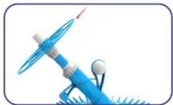
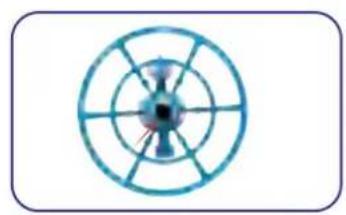
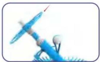
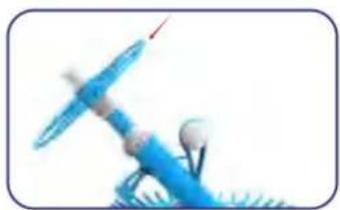
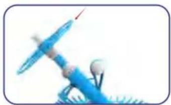
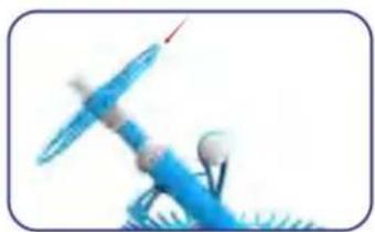
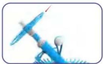
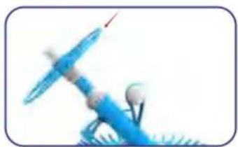
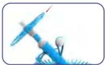
  • Ensure the wheel at the top of the Cleaner head is rotating freely.

5. Problem: Cleaner climbs out of the pool and draws in air.

Solution:

  • Ensure there is a valve installed in the skimmer/weir.
  • Inspect the Regulator Valve and flush away any debris build-up.
  • Verify proper hose length.

- Ensure cleaner sits flush with the pool floor. Adjust the position of the hose weight if necessary. This should be done at the deepest part of the pool.

6. Problem: Cleaner hose is tangling.

Solution:

  • Ensure the wheel on top of the Cleaner body is rotating freely and is screwed on securely.
  • Check that the hose sections are straight; if not, lay the hose in a straight line in the sun to relax the memory.
  • There may be too many hose sections for your pool. Try removing a section.
  • Inspect the Regulator Valve and flush away any debris build-up.

7. Problem: Cleaner won't leave the edge or rim of the pool.

Solution:

  • Utilize return jets to move cleaner.
  • Adjust hose weight.
  • Try decreasing the flow to your cleaner via the regulator. Less suction will allow the cleaner to move more freely.

8. Problem: Cleaner leaves patches.

Solution:

  • Ensure the wheel on top of the Cleaner body is rotating freely and is screwed on securely.
  • Adjust return jets downwards.
  • Verify proper hose length.
  • Ensure the cleaner sits flush with the pool floor. Adjust the position of the hose weight if necessary. This should be done at the deepest part of the pool.
  • Check that the hose sections are straight; if not, lay the hose in a straight line in the sun to relax the memory.

9. Problem: Cleaner sticks on walls and floors.

Solution:

  • Ensure there is a valve installed in the skimmer/weir.
  • Inspect the Regulator Valve and flush away any debris build-up.
  • Check the Mat for wear. Please note that if the mat is torn in these positions, operating is okay. (See Figure 9)
  • Try increasing or decreasing the flow to your cleaner via the regulator.

10. Problem: Cleaner is not sitting flat on the bottom.

Solution:

  • Ensure there is a valve installed in the skimmer/weir.
  • Inspect the Regulator Valve and flush away any debris build-up.
  • Ensure the wheel on top of the Cleaner body is rotating freely and is screwed on securely.
  • Adjust return jets downwards.
  • Verify proper hose length.

- Ensure the cleaner sits flush with the pool floor. Adjust the position of the hose weight if necessary. This should be done at the deepest part of the pool.

11. Problem: Air bubbles are noticeable in the return jets.

Solution:

  • Ensure the cleaner hose is assembled tightly.
  • Ensure the cleaner head is not removed from the water while the pump is running.
  • Ensure the hoses are not damaged.
  • Ensure the regulator valve is under water.
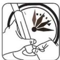
Illustration of a hand using a tool to interact with a circular diagram showing directional arrows (no text or symbols)

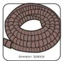
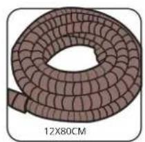
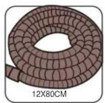
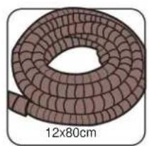
Illustration of a coiled cable or wire with no text or symbols on the diagram itself

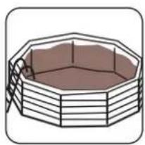
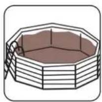
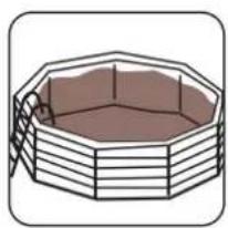
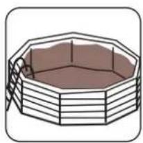
Illustration of a hexagonal octagonal structure with internal horizontal lines and a small figure on the left side (no text or symbols)

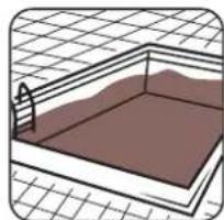
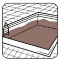
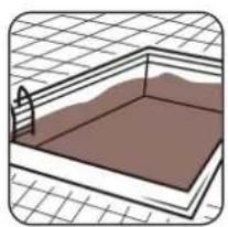
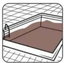
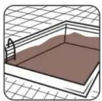
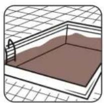
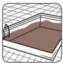
Illustration of a rectangular pool with horizontal walls and a curved top, set on a grid background (no text or symbols)

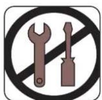
Prohibition sign with crossed wrench and screwdriver crossed out, enclosed in a circle

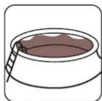
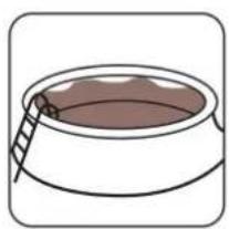
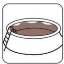
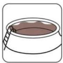
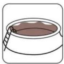
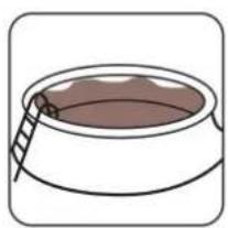
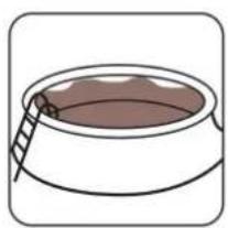
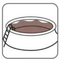
Simple line drawing of a container with a ladder inserted, no text or symbols present

1700gal/h or 6.5m³/h (MIN 0.75HP)

Circular mechanical component with radial blades and central hub (no text or symbols)

Close-up of a blue robotic arm mounted on a base with red alignment markers (no text or symbols visible)

White plastic T-shaped object with a red arrow pointing to a small cylindrical feature (no text or symbols visible)

Metal mechanical component with a circular top and flanged side, shown in 3D perspective (no text or symbols)

Figure 1 Figure 2 Figure 3 Figure 4aMetal mechanical component with a circular top and two flanges, showing a red curved arrow indicating rotation (no text or symbols)
Close-up of a blue and gray mechanical connector with a yellow-green center (no text or symbols visible)

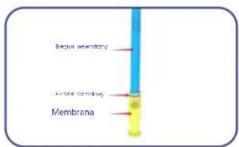
Inner Pole, Snap ring, Diaphragm

Blue circular object with radial blades and a central hole, no text or symbols present

Figure 4b Figure 5 Figure 6 Figure 7Close-up of a blue mechanical component with red circles highlighting features (no text or symbols visible)

Abstract blue circular pattern with radial symmetry (no text or symbols)

Illustration of a blue rocket-like object with a white base and tail, no text or symbols present

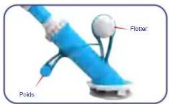
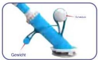
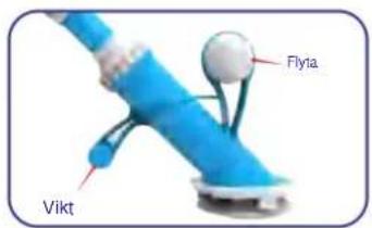
Float Weight

Figure 8 Figure 9 Figure 10 Figure 11

PRODUCT PARAMETER

Model PAC11
Swimming Pool Pump Power≥550W
Colour Blue and White
Product Size 525*453.5*430mm

Manufacturer: Shanghai Muxin Muye Youxiangongsi

Address: Shuangchenglu 803nong11hao1602A-1609shi, Baoshanqu, Shanghai 200000 CN.

Imported to AUS: SIHAO PTY LTD. 1 ROKEVA STREET EASTWOOD NSW 2122 Australia

Imported to USA: Sanven Technology Ltd. Suite 250, 9166 Anaheim Place, Rancho Cucamonga, CA 91730

Vevor PAC11 - PRODUCT PARAMETER - 1

E-CrossStu GmbH

Mainzer Landstr.69, 60329 Frankfurt am Main.

Vevor PAC11 - PRODUCT PARAMETER - 2

YH CONSULTING LIMITED.

C/O YH Consulting Limited Office 147, Centurion

House, London Road, Staines-upon-Thames, Surrey,

TW18 4AX

VEVOR®

TOUGH TOOLS, HALF PRICE

Technical Support and E-Warranty Certificate www.vevor.com/support

VEVOR®

TOUGH TOOLS, HALF PRICE

VEVOR®

TOUGH TOOLS, HALF PRICE

NEED HELP? CONTACT US!

ASSEMBLY STEP

Vevor PAC11 - ASSEMBLY STEP - 1

4Two grayscale images showing a wall-mounted device and a bowl-shaped object, both without any visible text or symbols.

63D rendered diagram of a pipe fitting with a central component and two side supports (no text or symbols)

Architectural floor plan sketch showing room layout and structural elements (no text or labels)

3D rendering of a pipe outlet with a valve and pipe fitting (no text or symbols visible)

Diagram of a pipe elbow joint with a support structure.

Illustration of a hand holding a tool near a circular dial with needle-like elements.

Illustration of a coiled brown cable or wire.

Illustration of a hexagonal metal frame with internal structure.

Illustration of a rectangular metal grate with a brown interior and a curved side, set against a grid background.

Prohibition sign with crossed wrench and screwdriver crossed out, enclosed in a circle.

Simple line drawing of a container with a ladder inside, no text or symbols present.

3D rendered mechanical component with no visible text or symbols on the body, labels, or symbols present.

Circular diagram with radial lines and central hub, no text or symbols present.

Close-up of a blue mechanical component with red markings, no visible text or symbols.

Figure 2 Figure 1

White plastic T-shaped object with a small red arrow pointing to its tip (no text or symbols visible).

Figure 3

3D rendered mechanical component with a curved arrow indicating rotational motion (no text or symbols).

Figure 4a

Metal mechanical component with a red arrow indicating rotational direction (no text or symbols).

Figure 4b Figure 6

Close-up of a blue and silver connector with a circular eye-like pattern (no text or symbols visible).

Figure 5

Abstract blue circular pattern with radiating spikes and a central hole, no text or symbols present.

Figure 7

Close-up of a blue mechanical component with red circular annotations highlighting features (no text or symbols visible).

Figure 8 Figure 9

Blue abstract fan-like shape with radiating blades, no text or symbols present.

Blue abstract fan-like shape with radial blades and central hole (no text or symbols).

Illustration of a blue rocket-like object with a white base and a red arrow pointing to it (no text or symbols).

Figure 10 Figure 11

Weight Float

PRODUCT PARAMETER

A/S YH Consulting Limited Office 147, Centurion

House, London Road, Staines-upon-Thames, Surrey,

TW18 4AX

VEVOR®

TOUGH TOOLS, HALF PRICE

VEVOR®

TOUGH TOOLS, HALF PRICE

VEVOR®

TOUGH TOOLS, HALF PRICE

www.vevor.com/support

Vevor PAC11 - TOUGH TOOLS, HALF PRICE - 1

4Two grayscale images showing a wall-mounted device and a bowl-shaped object, both without any visible text or symbols.

63D rendered diagram of a pipe fitting with a central component (no text or symbols)

Architectural cross-section diagram showing room layout and structural elements (no text or labels)

Diagram of a pipe outlet with a valve, showing airflow direction (no text or labels)

Diagram of a pipe elbow joint with a support structure (no text or labels)

Illustration of a hand holding a tool near a circular dial with needle-like elements (no text or symbols)

Illustration of a coiled brown cable or wire with no text or symbols

Illustration of a hexagonal metal frame with internal structure (no text or symbols)

Illustration of a rectangular metal grate with a brown interior and a curved side, set against a grid background (no text or symbols)

Prohibition sign with crossed wrench and screwdriver crossed out, enclosed in a circle

Simple line drawing of a container with a ladder inside, no text or symbols present

3D rendered mechanical component with no visible text or symbols, labeled (MIN. 0,75 PS)

Circular diagram with radial lines and central hub, no text or symbols present

Close-up of a blue mechanical component with red markings, no visible text or symbols

White plastic mechanical component with a red arrow indicating a feature (no text or symbols visible)

3D rendered mechanical component with a curved arrow indicating rotational motion (no text or symbols)

Close-up of a blue and white connector with a circular eye-like pattern (no text or symbols visible)

Inner pole, oscillation, membrane

Abstract blue circular graphic with radiating petal-like shapes and a central hole, no text or symbols present.

Illustration of a blue rocket-like object with a white base and a red arrow pointing to it (no text or symbols)

Figure 10

Weight, salendron

Figure 11

PRODUCT PARAMETERS

C/O YH Consulting Limited Office 147, Centurion

House, London Road, Staines-upon-Thames, Surrey,

TW18 4AX

VEVOR®

TOUGH TOOLS, HALF PRICE

VEVOR®

TOUGH TOOLS, HALF PRICE

VEVOR®

TOUGH TOOLS, HALF PRICE

SUCTION POOL CLEANER

MODEL: PAC11

3D rendered mechanical component with a central shaft and base, no visible text or symbols

ASSEMBLY PHASE

Vevor PAC11 - ASSEMBLY PHASE - 1

4Two grayscale images showing a wall-mounted device and a bowl-shaped object, both without any visible text or symbols.

63D rendered diagram of a pipe fitting with a hexagonal bolt, no text or symbols present.

Architectural floor plan sketch showing room layout and structural elements, no text or labels.

Diagram of a pipe outlet with a valve, showing airflow direction, no text or labels.

STEP 3: Remove the diaphragm from the inner pole.

4Illustration of a hand holding a pen and a tool, with an arrow indicating direction, no text or symbols.

Illustration of a hand holding a tool near a circular dial with needle-like elements, no text or symbols.

Illustration of a coiled, segmented cable or wire with no visible text or symbols.

Illustration of a hexagonal metal frame with internal structure, no text or symbols.

Illustration of a rectangular metal grate with a brown interior and a curved side, set against a grid background, no text or symbols.

Prohibition sign with crossed wrench and screwdriver crossed out, enclosed in a circle.

Simple line drawing of a container with a ladder inside, no text or symbols present.

3D rendered mechanical component with no visible text or symbols on the body itself.

Circular diagram with radial lines and central hub, no text or symbols present.

Close-up of a blue mechanical component with red markings, no visible text or symbols.

White plastic T-shaped object with a red arrow pointing to a small feature, no text or symbols visible.

3D rendered mechanical component with a curved arrow indicating rotational motion, no text or symbols.

Figure 1 Figure 2 Figure 3 Figure 4a
Metal mechanical component with a red curved arrow indicating rotation, no text or symbols.

Close-up of a blue and white connector with a circular eye-like pattern, no visible text or symbols.

Pola Interna Anolis elastica Diaframma

Abstract blue circular pattern with radiating spikes and a central hole, no text or symbols present.

Figure 5 Figure 4b Figure 6Close-up of a blue mechanical component with red circular annotations highlighting features, no visible text or symbols.

Figure 8

Abstract blue circular pattern with radial gradient and central hole, no text or symbols.

Figure 9

Illustration of a blue rocket-like object with a white base and a red arrow pointing to it, no text or symbols.

Figure 10 Figure 11

Calcitonar Peso

PRODUCT PARAMETER

C/O YH Consulting Limited Office 147, Centurion

House, London Road, Staines-upon-Thames, Surrey, TW184AX

VEVOR®

TOUGH TOOLS, HALF PRICE

VEVOR®

TOUGH TOOLS, HALF PRICE

VEVOR®

TOUGH TOOLS, HALF PRICE

ASSEMBLY STEP

Illustration of a mechanical tool interacting with two gear-like components, one showing a spiky wheel and the other a rotating shaft (no text or symbols).

Attach part "B" to part "A"

Mechanical assembly diagram showing two stages of a robotic arm with rotating components and a close-up inset (no text or symbols).

4Two grayscale images showing a wall-mounted device and a bowl-shaped object, both without any visible text or symbols.

63D rendered diagram of a pipe fitting with a central component and two side supports (no text or symbols).

Architectural floor plan sketch showing room layout and structural elements (no text or labels).

3D rendering of a pipe outlet with a valve and pipe fitting (no text or symbols visible).

Diagram of a pipe elbow joint with a support structure (no text or symbols).

Illustration of a hand holding a tool near a circular dial with needle-like elements (no text or symbols)

Illustration of a coiled brown cable or wire with a 12x80 cm thickness label (no other text or symbols)

Illustration of a hexagonal metal frame with internal structure (no text or symbols)

Illustration of a rectangular metal grate with a brown interior and a curved edge, set on a grid background (no text or symbols)

Prohibition sign with crossed wrench and screwdriver crossed out, enclosed in a circle

Simple line drawing of a container with a ladder inside, no text or symbols present

3D rendered mechanical component with no visible text or symbols on the part itself

Circular diagram with radial lines and central hub, no text or symbols present

Close-up of a blue mechanical component with red markings, no visible text or symbols

Figure 2

White plastic T-shaped object with a small red arrow pointing to its tip (no text or symbols visible)

Figure 3, Figure 1

3D rendered mechanical component with a curved arrow indicating rotational motion (no text or symbols)

Figure 4a

Metal mechanical component with a red arrow indicating rotational direction (no text or symbols)

Figure 4b, Figure 6

Close-up of a blue and silver connector with a circular eye-like pattern (no text or symbols visible)

Figure 5

Polo interior Ante de presto Diafragma

Guangliyun Smart Retail Cash Register System

Abstract blue circular pattern with radiating spikes and a central hole, no text or symbols present.

Figure 7

Close-up of a blue mechanical component with red circular annotations highlighting features (no visible text or symbols)

Figure 8, Figure 9

Blue abstract fan-like shape with radiating blades, no text or symbols present

Blue abstract fan-like shape with radial blades and central hole (no text or symbols)

Illustration of a blue rocket-like object with a white base and a red arrow pointing to it (no text or symbols)

Figure 10, Figure 11

Flotar Peso

PRODUCT PARAMETER

House, London Road, Staines-upon-Thames, Surrey,

TW18 4AX

VEVOR®

TOUGH TOOLS, HALF PRICE

VEVOR®

TOUGH TOOLS, HALF PRICE

VEVOR®

TOUGH TOOLS, HALF PRICE

SUCTION POOL CLEANER

MODEL: PAC11
3D rendered illustration of a mechanical device with a spherical head and angular blades, resting on a textured base (no text or symbols)

NEED HELP? CONTACT US!

PARTS LIST

Membrana ×1 Darmowy prezent A B C F G H x2 I E x1 D x11

ASSEMBLY STEP

Illustration of a mechanical tool interacting with two gear-like components, one showing a circular feature and the other with a pin (no text or symbols)

Architectural floor plan sketch showing room layout and structural elements (no text or labels)

Diagram of a pipe outlet with a valve, showing airflow direction (no text or labels)

Diagram of a pipe elbow joint with a support structure (no text or labels)

Illustration of a hand holding a tool near a circular dial with needle-like elements.

Illustration of a coiled brown cable or wire.

Illustration of a hexagonal metal frame with internal structure.

Illustration of a rectangular metal grate with a brown interior and a curved edge, set against a grid background.

Prohibition sign with crossed wrench and screwdriver crossed out, enclosed in a circle.

Simple line drawing of a container with a ladder inside.

3D rendered mechanical component with no visible text or symbols.

Circular diagram with radial lines and central hub.

Close-up of a blue mechanical component with red markings.

White plastic T-shaped object with a red arrow pointing to a small feature.

3D rendered mechanical component with a curved arrow indicating rotational motion.

Close-up of a blue and white connector with a circular eye-like pattern (no text or symbols visible)

Begin axonidry, Endol crossbow, Membrane

Abstract blue circular graphic with radiating petal-like shapes and a central hole, no text or symbols present.

Abstract blue circular pattern with radial symmetry (no text or symbols)

Figure 9Figure 8

Illustration of a blue rocket-like object with a white base and a red arrow pointing to it (no text or symbols)

Figure 10

Waga, Performer

Figure 11

PRODUCT PARAMETER

C/O YH Consulting Limited Office 147, Centurion

House, London Road, Staines-upon-Thames, Surrey,

TW18 4AX

VEVOR®

TOUGH TOOLS, HALF PRICE

VEVOR®

TOUGH TOOLS, HALF PRICE

Technical support and e-warranty certificate www.vevor.com/support

SUCTION CLEANER WITH SUCTION POOL

USER MANUAL

MODEL: PAC11

VEVOR®

TOUGH TOOLS, HALF PRICE

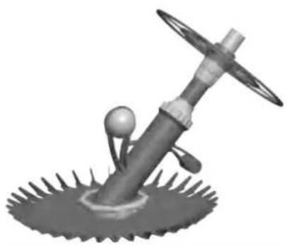
SUCTION CLEANER WITH SUCTION POOL

MODEL: PAC11
3D rendered illustration of a mechanical device with a spherical head and angular blades, resting on a textured base (no text or symbols)

NEED HELP? CONTACT US!

PARTS LIST

Diafragma x1 (Gratis geschenk), A, B, C, F, G, H x2, I, E x1, D x11

ASSEMBLY STEPS

Vevor PAC11 - ASSEMBLY STEPS - 1

4Two grayscale images showing a wall-mounted device and a bowl-shaped object, both without any visible text or symbols.

63D rendered diagram of a pipe fitting with a hexagonal bolt, no text or symbols present.

Architectural floor plan showing room layout and structural elements, no text or labels.

Diagram of a pipe outlet with a valve, showing internal flow and structural components, no text or labels.

Diagram of a pipe elbow joint with a support structure, no text or labels.

Illustration of a hand holding a tool near a circular dial with needle-like elements (no text or symbols).

Illustration of a coiled brown cable or wire (no text or symbols).

Illustration of a hexagonal metal frame with internal structure (no text or symbols).

Illustration of a rectangular metal grate with a brown interior and a curved edge, set against a grid background (no text or symbols).

Prohibition sign with a crossed-out wrench and screwdriver enclosed in a circle.

Simple line drawing of a container with a ladder inside (no text or symbols).

3D rendered mechanical component with no visible text or symbols on the body, labels, or annotations.

Circular diagram with radial lines and a central hub (no text or symbols).

Close-up of a blue mechanical component with red markings (no visible text or symbols).

Figure 2 Figure 1

White plastic T-shaped object with a small red arrow pointing to its tip (no text or symbols visible).

Figure 3

3D rendered mechanical component with a curved arrow indicating rotational motion (no text or symbols).

Figure 4a

Metal mechanical component with a red curved arrow indicating rotation (no text or symbols).

Figure 4b

Close-up of a blue and white connector with a circular eye-like pattern (no text or symbols visible).

Figure 5

Binnorste pool, Borgring, Dialragma

Figure 6

Abstract blue circular graphic with radiating petal-like shapes and a central hole (no text or symbols).

Figure 7

Close-up of a blue mechanical component with red circular annotations highlighting features (no text or symbols visible)

Abstract blue circular pattern with radial symmetry (no text or symbols)

Figure 8 Figure 9

Illustration of a blue rocket-like object with a white base and a red arrow pointing to it (no text or symbols)

Figure 10

Vevor PAC11 - ASSEMBLY STEPS - 25

C/O YH Consulting Limited Office 147, Centurion

House, London Road, Staines-upon-Thames, Surrey,

TW18 4AX

Machine Translated by Google

VEVOR®

TOUGH TOOLS, HALF PRICE

Technical support and e-warranty certificate www.vevor.com/support

Machine Translated by Google

VEVOR®

TOUGH TOOLS, HALF PRICE

VEVOR®

TOUGH TOOLS, HALF PRICE

SUGBAGSRENARE

MODEL: PAC11
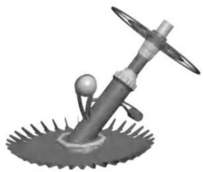
3D rendered illustration of a mechanical device with a spherical head and angular blades, resting on a circular base (no text or symbols)

NEED HELP? CONTACT US!

ASSEMBLY STEPS
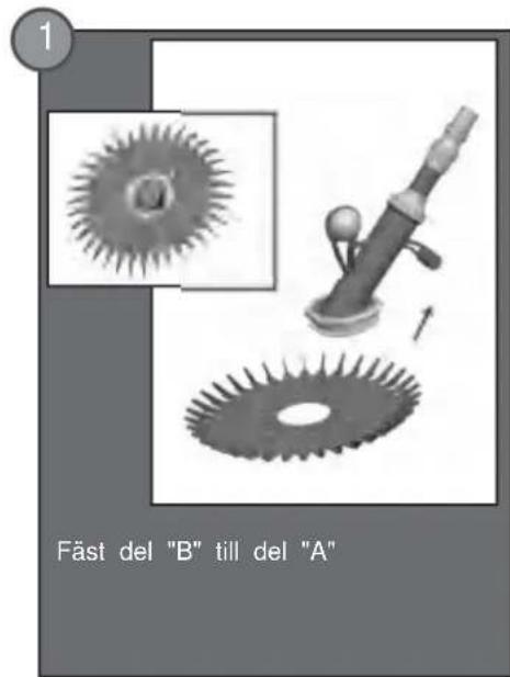
Vevor PAC11 - ASSEMBLY STEPS - 1

4Two grayscale images showing a wall-mounted device and a bowl-shaped object, both without any visible text or symbols.

63D rendered diagram of a pipe fitting with a hexagonal component inserted, no text or symbols present

Architectural floor plan sketch showing room layout and structural elements (no text or labels)

Diagram of a pipe outlet with a valve, showing airflow direction (no text or labels)

Illustration of a hand holding a tool near a circular dial with needle-like elements (no text or symbols).

Illustration of a coiled brown cable or wire with a 12x80cm thickness label (no other text or symbols).

Illustration of a hexagonal metal frame with internal structure (no text or symbols).

Illustration of a rectangular metal grate with a brown interior and a curved side, set against a grid background (no text or symbols).

Prohibition sign with crossed wrench and screwdriver crossed out, enclosed in a circle.

Simple line drawing of a container with a ladder inside, no text or symbols present.

1700 gal/h or 6.5 m³/h (MIN 0.75 hp)

Circular diagram with radial lines and central hub, no text or symbols present.

Close-up of a blue mechanical component with red markings, no visible text or symbols.

White plastic mechanical component with a red arrow pointing to a small feature, no text or symbols visible.

3D rendered mechanical component with a curved arrow indicating rotational motion, no text or symbols.

Figure 2 Figure 4a Figure 3 Figure 1Metal mechanical component with a red curved arrow indicating rotation, no text or symbols.
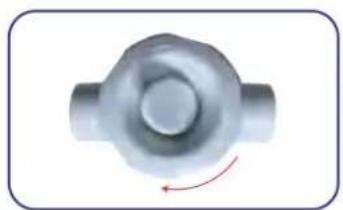
Close-up of a blue and white connector with a circular eye-like pattern, no text or symbols visible.

Inre pol Snäppring Membran

Abstract blue circular graphic with radiating petal-like shapes and a central hole, no text or symbols present.

Figure 8 Figure 9

Abstract blue circular pattern with radial symmetry, no text or symbols.

Illustration of a blue propeller with a white base and spout, no text or symbols present.

Figure 10 Figure 11

Flyia Vikt

PRODUCT PARAMETERS

C/O YH Consulting Limited Office 147, Centurion

House, London Road, Staines-upon-Thames, Surrey,

TW18 4AX

VEVOR®

TOUGH TOOLS, HALF PRICE

Manual assistant
Powered by Anthropic
Waiting for your message
Product information

Brand : Vevor

Model : PAC11

Category : Pool vacuum