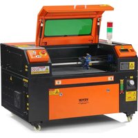
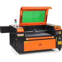
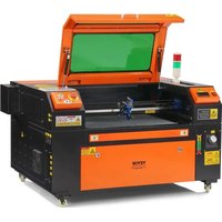
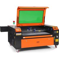
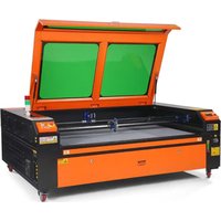
USER MANUAL KH5030 Vevor
Technical Support and E-Warranty Certificate www.vevor.com/support
LASER ENGRAVING MACHINE
INSTRUCTION MANUAL
MODEL: KH5030/KH6040/KH7050/KH906/KH1490 KH-5030/KH-6040/KH-7050/KH-906/KH-1490
We continue to be committed to provide you tools with competitive price. "Save Half", "Half Price" or any other similar expressions used by us only represent the estimate of savings you might benefit from buying certain tools with us compared to top brands and does not necessarily mean to cover all categories of tools offered. We are kindly reminded to verify carefully when you are placing an order with us actually saving half in comparison with the top major brands.
MODEL: KH5030/KH6040/KH7050/KH9060/KH1490
KH-5030/KH-6040/KH-7050/KH-906/KH-1490
Have product questions? Need technical support? Please feel free to contact us:
Technical Support and E-Warranty Certificate www.vevor.com/support
This is the original instruction. Please read all manual instructions carefully before operating. VEVOR reserves a clear interpretation of the user manual. The appearance of the product shall be subject to the product you received. Please forgive us that we won't inform you if there are any technology or software updates on our product.
| Warning-To reduce the risk of injury, user must read instructions manual carefully. |
| This device complies with Part 15 of the FCC Rules. is subject to the following two conditions:(1)This device not cause harmful interference, and (2)this device must any interference received, including interference that may cause undesired operation. |
| This product is subject to the provision of European D 2012/19/EC. The symbol showing a wheelie bin crossed through indicates that the product requires separate refu collection in the European Union. This applies to the p and all accessories marked with this symbol. Products as such may not be discarded with normal domestic w must be taken to a collection point for recycling elec tri electronic devices |
IMPORTANT NOTES
CO2 laser engraver is suitable for both personal and professional use. When used in accordance with these instructions, it includes a Class laser system, but some components are still very dangerous. Never disable pre-installed safety equipment and always use the laser safely and responsibly.
Before operating the equipment, the user must carefully read the operation manual and strictly abide by it. This manual is applicable to multiple models of products.
- This equipment uses international standard four types of lasers (stror laser radiation). Laser radiation may cause the following events:
- Ignite surrounding combustibles. 2. During the laser processing, due to different processed objects, radiation and other toxins may be generated. Harmful gas.
- Direct laser radiation may cause personal injury. Therefore, the equipment must be equipped with fire-fighting equipment. It is strictly forbidden to stack flammable and explosive materials on the workbench and around the equipment. At the same time, ensure ventilation. Non-professional operators are not allowed to approach the equipment.
- Laser processing objects and emissions should comply with local laws and regulations.
- Laser processing may have high risks, so you should carefully consider whether the object is suitable for laser processing.
- The internal laser equipment has high voltage and other dangers. For equipment operators, it is strictly prohibited to disassemble.
- When the equipment is turned on, someone must be guarded. Unauthorized leaving is forbidden, and all power must be cut off before personnel leave.
- It is forbidden to open any door when the equipment is working.
- Before starting operation, this equipment and other equipment must be safely and effectively grounded.
- Do not place any irrelevant total reflection or diffuse reflection objects in the equipment to prevent the laser from being reflected on human body or flammable objects.
Objects in the equipment to prevent the laser from being reflected on human body or flammable objects.
- During the operation of the equipment, the operator must always observe the operation of the equipment. If an abnormal situation occurs, please immediately.
- The equipment should be in a dry, pollution-free, vibration-free and safe electromagnetic interference environment, with a working temperature of 5-40 degrees Celsius and a humidity of 5-95% (non-condensing water environment).
- The equipment should always be far away from electrical equipment sensitive to electromagnetic interference, otherwise it may cause electromagnetic interference.
- The working voltage of the device is: European AC220V or North American AC120V (please confirm the working voltage of the device before use).
- The most important carbon dioxide glass laser in the equipment is a consumable and a vulnerable item. Please take care of it during use. Carbon dioxide glass laser needs pure cold water to cool down. Please pay attention to the water temperature not to exceed 30 degrees C during use, otherwise the laser will be damaged. When the ambient temperature is about to drop below 0 degrees Celsius, please replace with an antifreeze liquid to avoid damage to the carbon dioxide glass laser.
- It is forbidden to turn on the equipment when the grid voltage is up or mismatched. The manufacturer and seller are not responsible for loss caused by incorrect use or non-compliance with the above regulations.
This manual is a designated user guide for cabinet laser engraver installation, setup, safe operation, and maintenance. It covers general information, safety instructions, installation steps, operating instructions, maintenance procedures, and contact information.
All personnel involved in the installation, setup, operation, maintenance, and repair of this machine should read and understand this manual, especially its safety instructions. Some components have extremely high voltages and/or generate powerful laser radiation. Substandard performance and longevity, property damage, and personal injury can result from not understanding and following these instructions.
Your laser engraver works by emitting a powerful laser beam from a glass tube filled with insulating carbon dioxide (CO2), reflecting that beam off three mirrors and reflecting it through a focusing lens, and using focused light to etch the design onto certain substrates. The first mirror is fixed near the end of the laser tube, the second mirror travels along the Y-axis of the machine, and the third mirror is attached to the laser head traveling along the X-axis. Since some of the dust from the engraving process settles on the mirrors, they need to be cleaned frequently. Since they move during operation, they also need to be readjusted periodically with the set screws to which they are attached to maintain the correct laser path. A water-cooled system (usually a pump or cooler) must be used with this engraver to dissipate the heat generated by the laser tube. Similarly, an exhaust system (usually an external vent or a dedicated air purifier) must be used to remove the dust and gases generated during the engraving process.
Running your laser consistently above 70% of its maximum power rating will significantly shorten its lifespan. It is recommended to set it at 10-70% of the maximum rated power for optimal performance and longevity.
Please note that this is a high-voltage device and for safety reasons, it is recommended to only touch its components with one hand at a time during use.
Note that active lasers are invisible to the human eye. This applies
should not be used with any lid open to avoid potential permanent injury. It should also be noted that both the cooling water system and the exhaust system are absolutely necessary for the safe use of this equipment. Do not operate the engraving machine without these two systems functioning properly. The water should always be clean and kept around room temperature, and the exhaust system should always comply with all laws and regulations applicable to the workplace and ambient air quality.
SYMBOL GUIDELINES
The following symbols are used on the label of this machine or in the manual:

These items carry a risk of serious property damage or personal injury.
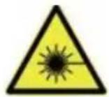
These projects solve similar serious problems related to laser beams.
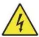
These projects solved similar serious problems with electrical components.

Anyone around the unit should wear protective glasses during operation.
INTENDED PURPOSE
- The machine is suitable for engraving logos and other consumer products on applicable substrates. This laser can process a variety of materials, including wood and cork, paper and cardboard, most of the glass, cloth and leather, and stone. It can also be used with some specially coated metals. Use of this system for purposes or material other than those for which it is specified is not permitted.
- The system must be operated, maintained, and repaired by a person who is familiar with the field of use and hazards of the machine and materials, including its reflectivity, electrical conductivity, potential for production of harmful or combustible fumes, etc.
- Laser beams are dangerous. The manufacturer and/or seller shall not be liable for any improper use of this device or for any damage or injury resulting from use. It is the operator's obligation to use this cabinet engraver only in accordance with its intended use, other instructions in the manual, and all applicable local and national laws and regulations.
SPECIFICATIONS
| Model | KH5030 | KH6040 | KH7050 | KH9060 | KH1490 |
| KH-5030 | KH-6040 | KH-7050 | KH-9060 | KH-1490 |
| Input voltage | AC 120V | AC 120V | AC 120V | AC 120V | AC 120V |
| AC 230V | AC 230V | AC 230V | AC 230V | AC 230V |
| Total power | 420W | 560W | 680W | 830W | 900W |
| Laser power | 50W | 60W | 80W | 100W | 130W |
| Working area | 500*300m m | 600*400m m | 700*500m m | 900*600mm | 1400*900m m |
| temperature | 5-50 °C |
| humidity | 5%-95% non-condensate |
| Laser type | CO2 glass lasers |
| Laser model | KH-LT50 | KH-LT60 | R3 | R5 | R7 |
| Material | Stone, wood, ceramic, metal, cloth, paper, etc |
| Workbench | Cellular platform |
| Cutting speed | 0-400mm/s |
| Engraving speed | 0-500mm/s |
MAIN COMPONENTS AND DESCRIPTIONS
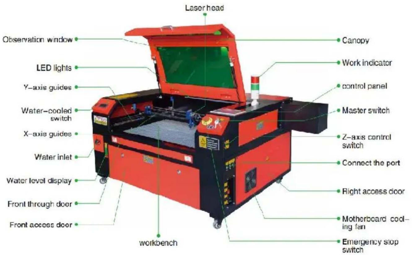
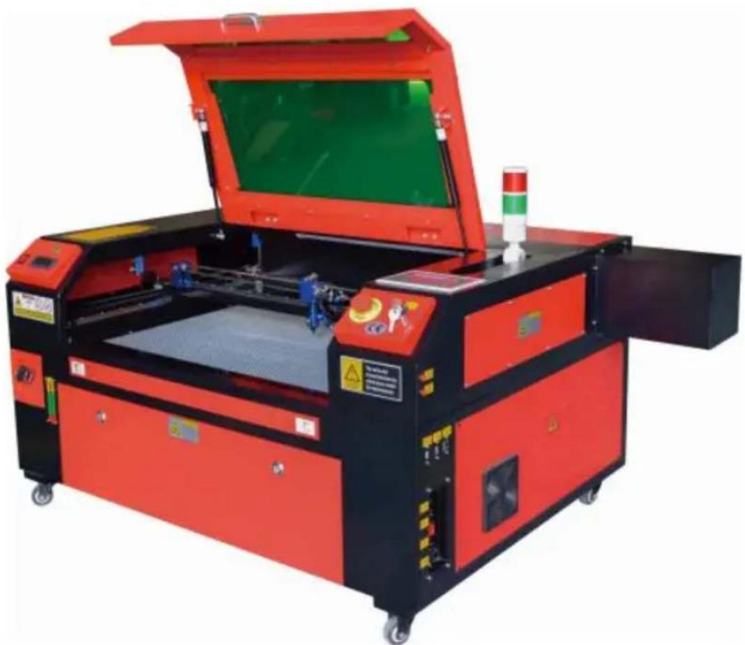
1. Schematic diagram of the part.
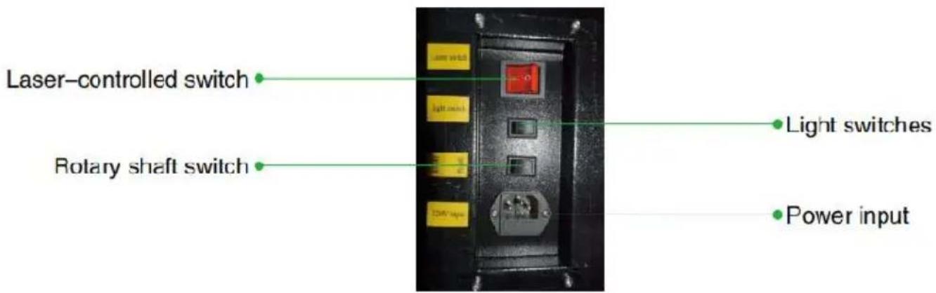
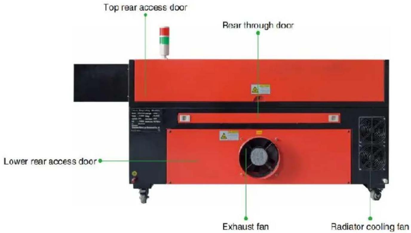
2. Part Description.
- Viewing window: This tan acrylic window allows you to monitor the engraving process, but only partially absorbs the high infrared laser. It has no other protection. Always wear glasses when using the Prote Observation Active Laser and never stare at it for long periods of time.
- LED Light: This light green light illuminates the workbench for a clear view of the material engraving before, during, and after work.
- Y-axis guides: Y-axis guides allow X-axis guides to move back and forth on the table.
- Water cooling switch: After the switch is activated, the built-in water cooling starts, and the real-time temperature display lights up.
- X-Axis Rail: The X-axis rail holds the second mirror and supports the laser head to move left and right.
- Water inlet: This is used to unscrew the lid counterclockwise when the built-in circulating water tank.
- Water level display: This observation port can be used to observe the water level of the water tank in the fuselage. (yellow: too high / green: suitable / red: too little).
- Front Straight Door: This door opens to allow larger materials to pass through the work bed. Extreme care must be taken to avoid seeing
suffering from the laser beam and its reflections. This is also where the accessory bag was when the engraver first arrived.
- Front Access Door: This door provides access to the area below the bench for easy cleaning.
- Canopy: The lid provides access to the main bracket for placing and retrieving materials, as well as fixing laser path alignment and other maintenance. When the lid is opened, the power of the laser is automatically cut off.
- Working indicator: It can help the operator to better observe the laser emission status, red light: laser working, green light: laser idle.
- Control Panel: The control panel provides manual control of the engraving process, including the movement of the manual laser head and the emission of the laser.
- Main switch: control the total power switch of the whole machine.
- Z-Axis Control Switches: These buttons move the table up or down to help you quickly adapt and focus on the various thicknesses of the
- Connection Ports: These ports connect the main board of the engraving machine to the control computer and its engraving software via a port or Ethernet cable.
- Right Access Door: This door provides access to the motherboard, drivers, and power supply. The vents prevent the components from overheating during use and should not be obstructed.
- Motherboard cooling fan: This fan is used for heat dissipation of coil appliances such as built-in motherboards and laser power supplies.
- Emergency Stop Switch: In case of emergency, this button will immediately cut off all power to the laser tube.
- Laser Head: The laser head holds the 3rd mirror, focusing lens, rec guidance, and air assist outlet.
- Table: Table height can be adjusted to accommodate thinner and thicker materials, as well as between aluminum and cellular platforms.
Laser Control Switch: This switch must be turned on when using a
Light switch: Turn on the light on the workbench.
- Rotary axis switch: This switch must be turned on when using the rotary axis (off when the rotary axis is not in use), if the Y axis is not
check if this switch is off.
- Power Input: This power connector must be connected before using machine.
- Top Rear Access Door: This door leads to the laser bay where the tube and its connections are secured.
- Rear Door: This door is the equivalent of a front door and requires care during use.
- Lower Rear Access Door: This door provides access to the air assist pump and Z-axis belt.
- Exhaust fan: This fan extracts gas and debris from the air from the workbench and sends the air out after being purified by an eco-fries filter.
- Water Tank Cooling Fan: This fan is used to cool the circulating water.
3. Laser path description.
A. Laser tube: This glass tube filled with carbon dioxide is mounted on a bracket and cannot be moved. The connection voltage between it and the laser power supply is extremely high and extremely dangerous. B. First reflector — This adjustable angle mirror is held in place to transfer the engraving laser from the tube to the second mirror.
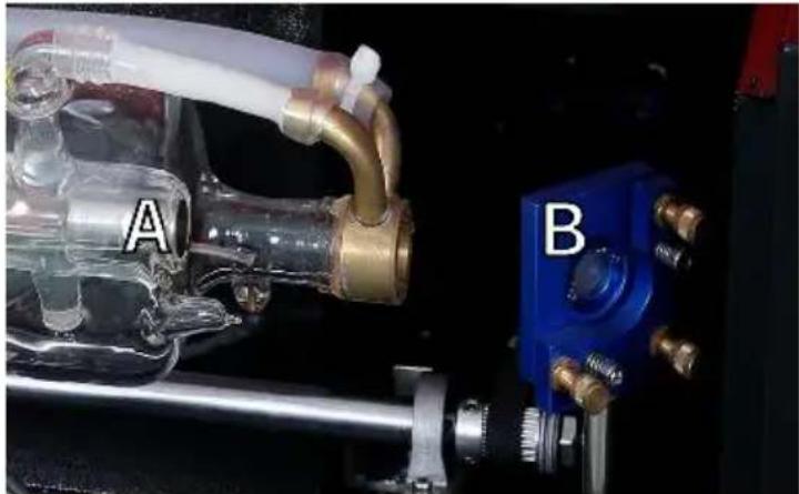
C. Second mirror: This adjustable angle mirror moves along the X-axis, guided to allow the laser beam to travel along the Y-axis. D. Third mirror: This angle-adjustable mirror moves with the laser head allowing the laser beam to travel along the X-axis.
E. Focusing Lens: This lens directs and focuses the laser light onto material.
F. Workbench: The height of the exposed workbench can be adjusted.
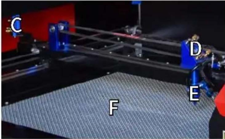
4. Connect the inputs.
A. USB Line Port: This port uses any of its USB ports to connect control computer and its engraving software.
B. USB Port: This port allows you to load and save designs and parameters directly to the engraver.
C. Ethernet port: This port connects directly or via the Internet to the control computer and its software.
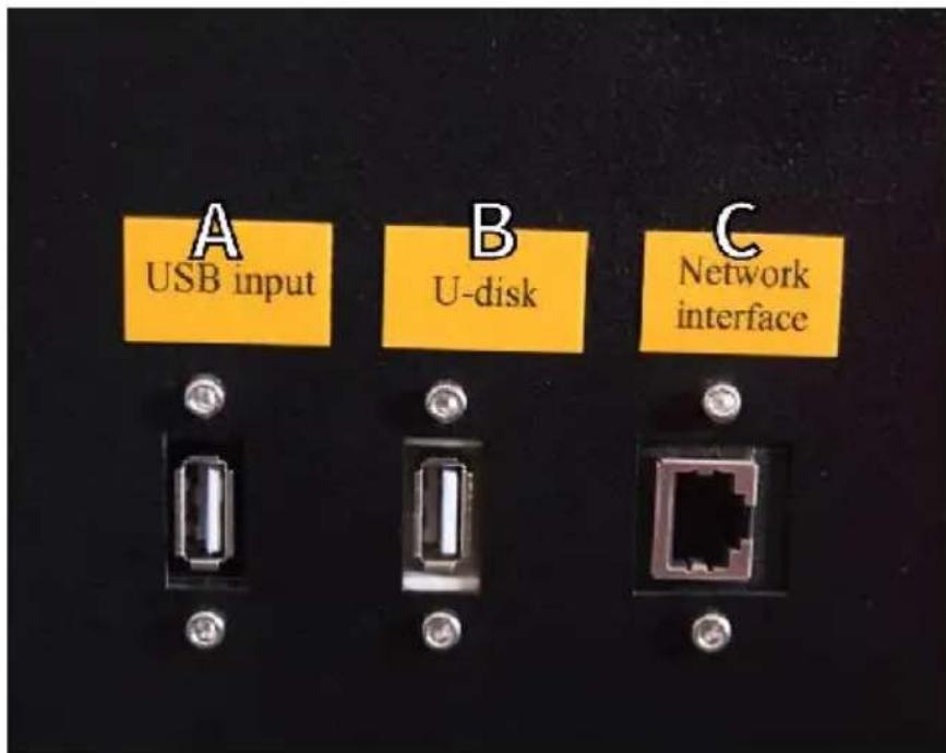
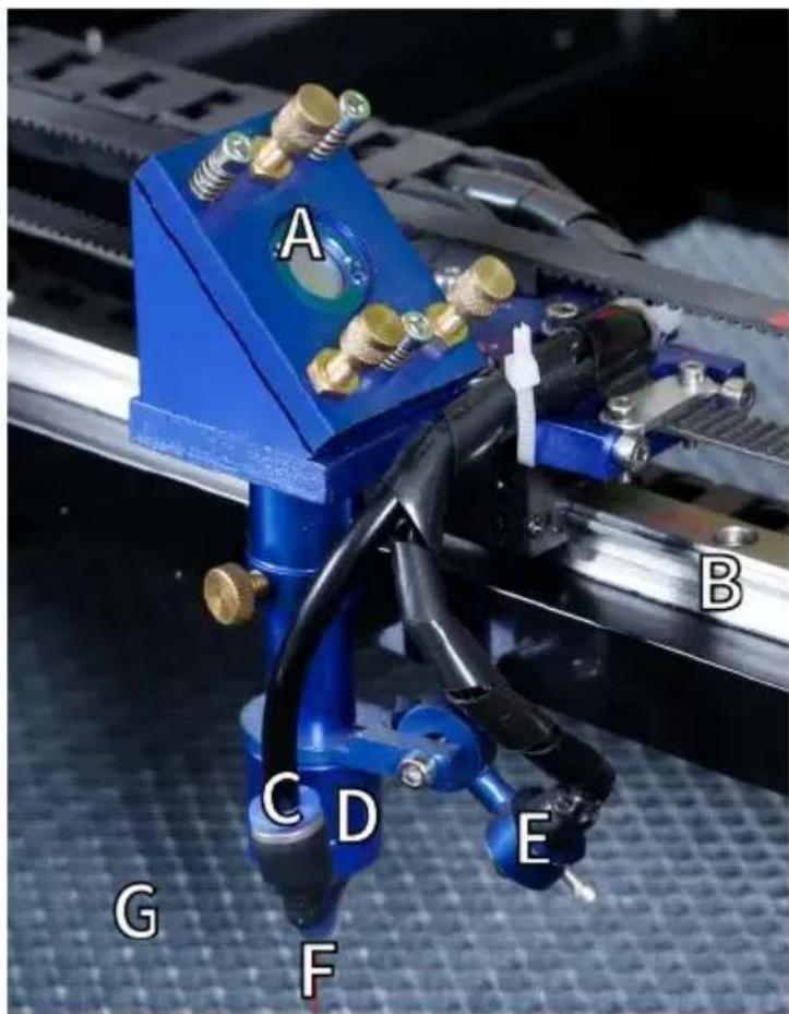
5. Laser head assembly.
A. Laser Head Third Mirror: This angle-adjustable mirror transmits light from the second mirror to the focusing lens. B. X-axis guide: This guide moves along the Y-axis, and its movement is controlled by a limit switch. C. Air Assist: This device blows pressurized air to kill sparks and away gases and debris while engraving. D. Focusing Lens: This lens directs and focuses the laser beam to point of contact with the engraving material. E. Red Dot Pointer: This device helps you see the exact location of invisible engraving laser. F. Laser: The engraving laser itself is invisible, but very dangerous. A direct contact with skin or eyes. G. Workbench: Use the acrylic tools provided to achieve the perfect focus for any thickness of material.
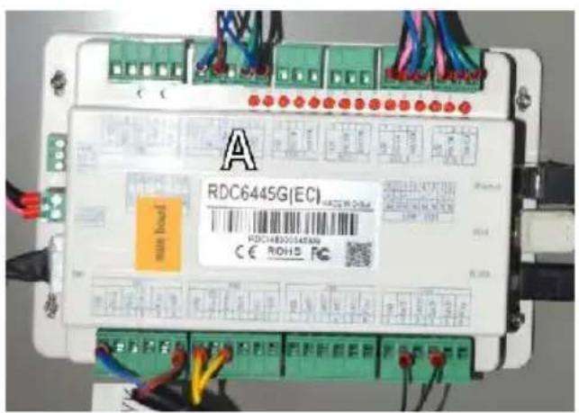
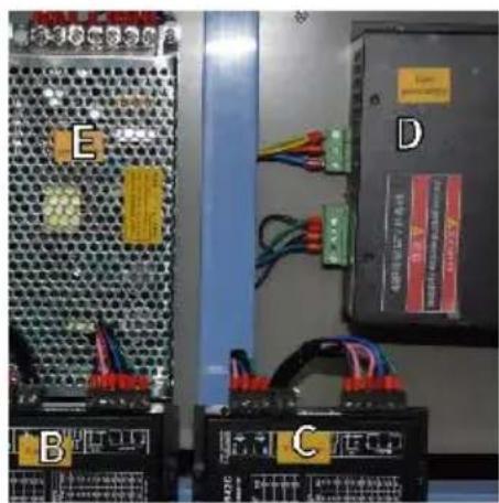
- Right access door.
A. Motherboard: This board controls the engraving process and responds to commands from the engraving software or the machine's control panel. B. X-axis driver: This device moves the laser head along the X-rail. C. Y-axis drive: This device moves the X-rail along the Y-rail. D. Laser Power: This device converts standard electricity into the extremely high voltage charge required for a laser tube. E. Power Supply: This device powers the machine's motherboard and drives.
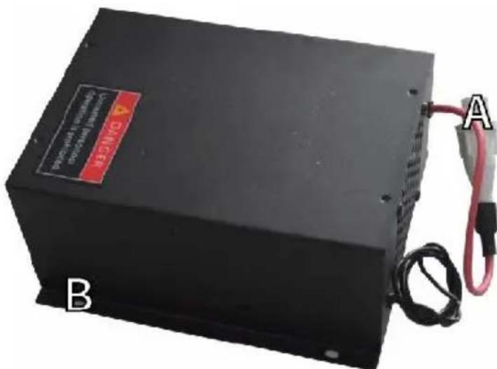
7. Laser power supply.
A. High-voltage wire: This wire is connected to the anode or positive of the laser tube and provides high-voltage current to power the B. Mounting Holes: These standard slots allow for simple installation removal.
8. Control the display.
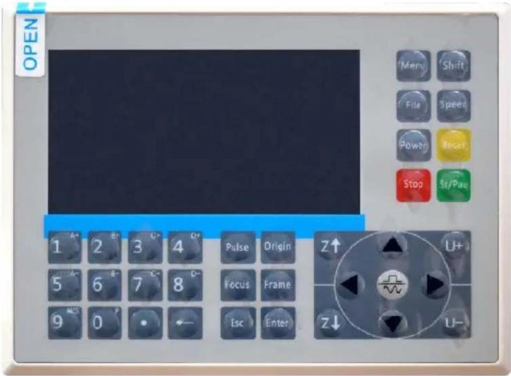

Reset button: System reset

Stop button: Stop machining or motor shaft movement

Delete key: This parameter is used to delete the parameter

Anchor key: Set the anchor point

Point Shot Button: The laser tube is pointed at the light

OK key: Used for user confirmation

Autofocus key: Automatically finds the locus point

Speed key: Sets the current machining speed value


Z-axis key: Used to move the Z-axis


U-axis key: Used to move the U-axis

Start/Pause key: Start work or pause/restart work

Decimal Point: Used to set parameters with decimals

Power button: Set the current maximum and minimum power values

Jog/Continuous Key: Jog motion and continuous motion switching

Toggle keys: Combine with number keys to form key combinations, or toggle special functions

Exit key: Used to return to the previous menu, cancel parameter settings, etc.

Menu keys: user parameters, manufacturer parameters, language settings, etc.

Border Key: Performs a boundary traversal operation on the file being processed

File Keys: Memory file and USB flash drive file management

D-pad: Used to move options when setting parameters in the menu
Numeric keys 0-9: used to set parameters, the keys with characters in the upper right corner can be combined with the toggle keys
-Display description
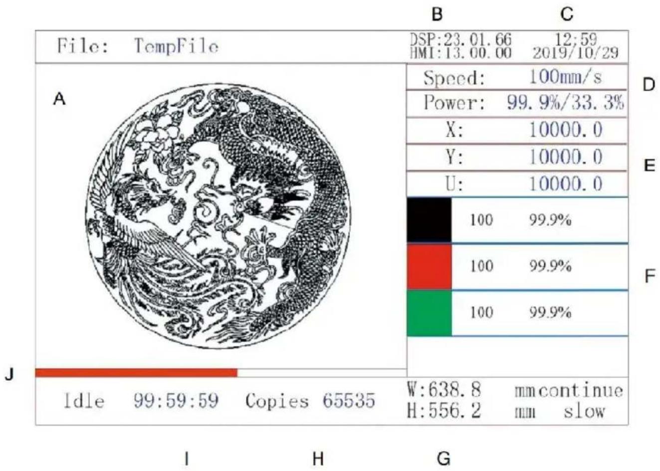
A. Graphical display area: Displays the track and running track of the entire file. B. Version Number: Displays the version number of the panel and motherboard. C. System Time: Displays the current system time. D. Parameter display area: display the file number, speed, maximum power, etc. of the running file. E. Coordinate Display Area: Displays the current coordinates of the laser head. F. Layer Display Area: Displays the layer parameters of the current or preview file. The parameters from left to right are the number of laser color, speed, and maximum power. G. Frame Size Processed: Displays the dimensions of the current file. H. Number of Pieces: Displays the count of completed runs for the file.
I. System Status: Displays the current status of the machine: idle, run paused, or completed. The processing time is shown on the right. J. Processing Progress Bar: Displays the progress of the current file.
Note: When the system is idle or when the work is complete, all buttons are used. Users can work on files, set parameters, preview files, and some buttons will not work when the work is running or paused (for example, origin and frame).
1. DISCLAIMER OF WARRANTIES
Your engraver may be slightly different from the one shown in this manual due to options, updates, etc. If your engraving machine comes with an outdated manual or you have any other questions, please contact
2. GENERAL SECURITY NOTICE
Your device should have an instruction label attached in the following locations:
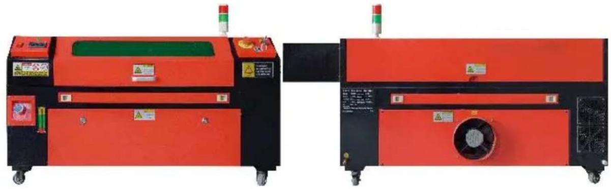
- If any of these tags are missing, illegible, or damaged, they must be replaced.

- Use this laser engraving device only in accordance with all applicable local and national laws and regulations.
- Use this appliance only in accordance with this instruction manual. (C) Others who have read and understood this manual are allowed to operate, maintain, repair, etc. If this device has been given away to a third party, make sure this manual is included with this device.
- Do not run continuously for more than 3 and a half hours. Stop for 30 minutes between uses.
- Do not leave this device unattended during operation. Observe the equipment throughout the operation. If there is any abnormal operation, cut off all power to the machine immediately, and contact our customer service or your specialized repair service. Again, make sure the appliance is completely turned off after each use (including via the emergency stop switch).
- Do not allow minors, untrained personnel, or persons with physical or mental disabilities that would interfere with their ability to follow this manual and software manuals to install, operate, maintain, or repair equipment.
- Any untrained personnel who may be in close proximity to the equipment while operating must be informed that the equipment is dangerous and given adequate instructions on how to avoid injury during use.
- Always place fire extinguishers, water pipes, or other flame retardant systems nearby to prevent accidents. Make sure the phone number of the local fire department is clearly displayed nearby. In the event of a fire, cut off the power supply before extinguishing the flames. Before use, familiarize yourself with the correct range of the fire extinguisher. Be careful not to use the fire extinguisher too close to the flame, as pressure can create a backlash.
3. LASER SAFETY INSTRUCTIONS.
When used as directed, the machine includes a Class 1 laser system that is safe for both users and bystanders. However, invisible lasers, tubes, and their electrical connections are still very dangerous. They can cause serious property damage and personal injury if not used or maintained
with care, including but not limited to the following:
Lasers can easily burn nearby combustible materials.
- Some working materials may produce radiation or harmful gases during processing.
- Direct contact with the laser can cause bodily harm, including severe burns and irreparable eye damage.
- Do not modify or disable the security features provided by this device, do not modify or disassemble the laser, and do not use the laser if it has been modified or disassembled by anyone other than a trained and skilled professional. Dangerous radiation exposure and other injuries can result from the use of adapted, modified, or otherwise incompatible equipment.
- Never keep any part of the cabinet open during operation unless required through doors. Never interfere with the laser beam, do not place any part of the body on any part of the laser path during operation, and never attempt to observe the laser directly. When using a pass-through door or otherwise risking exposure to a laser beam, take steps to protect yourself from potentially reflected laser beams, including the use of personal protective equipment, such as specially designed protective eyewear, to filter for specific wavelengths of lasers with an optical density (OD) appropriate for the laser.
- During operation, do not stare or allow others to stare at the laser continuously, even if the lid is closed and/or protective glasses are worn.
- Use this engraving machine only when its auto-shut-off function is working properly. When you first get this engraver, if you subsequently notice any issues, test it before doing any other work (see below).
If closure does not occur, do not continue to use it. Turn off the device and contact customer service or repair service. Never disable these closure mechanisms.
- If the water cooling system is not working properly, do not use this engraver under any circumstances. Always activate the water cooling system and visually confirm that the water is flowing through the end system before turning on the laser tube. Do not use ice water or water with temperatures higher than 100°F (38°C). For best results, keep between 60–70°F (15–21°C).
- Do not use generic coolant or antifreeze in the cooling water, as they can leave a corrosive residue and solidify inside the hose and pipes, which can lead to failure or even explosion. Use a custom laser-safe formula or use and store your engraver in a climate-controlled area.
- Do not leave potentially flammable, explosive, or corrosive materials nearby to avoid exposing them to direct or reflected laser beams.
- Do not use or place sensitive EMI equipment nearby. Make sure the area around the laser is free of strong electromagnetic interference during any use.
- Use this machine only for the processing of materials described in the Material Safety section of this manual. The laser setup and engraving process must be appropriately adjusted for the specific material.
- Ensure that the area is free of other air pollutants as these may pose a similar risk of reflection, combustion, etc.
4. ELECTRICAL SAFETY INSTRUCTIONS.
- Use this device only with a compatible and stable power supply with voltage fluctuation of less than 10%.
- Do not connect other devices to the same fuse as the laser system requires its full amperage. Do not use with standard extension cords or power strips. Only surge protective devices with a rating of more than 2000 J should be used.
- Power this device on only if this device is well grounded, either by connection to a 3-pin socket or by a dedicated grounding cable that is securely connected to the correct slot on the cabinet. Do not use ungrounded 3-to-2-pin adapters. The grounding of the equipment should be checked regularly for any damage or loose connections.
- Therefore, the area around this laser engraving device should be kept dry, well ventilated, and environmentally controlled to keep the ambient temperature between 40–95°F (5–35°C). For best results, keep the temperature at 75°F (25°C) or lower. The ambient humidity should not exceed 70%.
- When the pump is connected to its power source, do not handle the pump or the water it is submerged in. Put it in the water before connecting it to a power source and disconnect it from the power before taking it out.
- Adjustments, maintenance, and repairs of the electrical components of this equipment must be done only by trained and skilled professionals to avoid fire and other failures, including potential radiation exposure due to damage to laser components. Since testing the electrical components of this marking system requires specialized techniques, it is recommended that such testing should only be carried out by manufacturers or seller repair service organizations. Unless otherwise noted, adjust, maintain, and repair the appliance only when it is turned off, disconnected from power, and completely cool.
5. MATERIAL SAFETY INSTRUCTIONS.
- It is the responsibility of the user of this laser engraving machine to confirm that the material to be processed is able to withstand the laser and does not produce any emissions or by-products that are harmful to nearby people or that violate local or national laws or regulations. In particular, do not use this equipment to process polyvinyl chloride (PVC), Teflon, or other halogen-containing materials under any circumstances.
- It is the responsibility of the user of this laser engraving machine to ensure that everyone present during operation has adequate personal protective equipment to avoid injuries caused by emissions and by-products of the material being processed. In addition to the laser protective glasses mentioned above, this may require goggles, masks, respirators, gloves, and other protective outerwear.
- If the exhaust system is not working properly, do not use this laser engraving machine under any circumstances. Always ensure that the exhaust fan is able to remove dust and gases from the engraving process in accordance with all applicable local and national laws and regulations. If the exhaust fan or exhaust pipe fails, stop using it immediately.
- Users must be especially careful when working with conductive materials, as the build-up of dust and environmental particles may damage electrical components, cause short circuits, or have other effects, including reflected laser radiation.
- This machine is safe to use with the following materials: 1. Plastics.
- Acrylonitrile butadiene styrene (ABS)
- Nylon (polyamide, PA, etc.) polyethylene
- High-density polyethylene (HDPE, polyethylene, etc.)
- Biaxially oriented polyethylene terephthalate (BoPET, polyester, etc.)
- Polyethylene terephthalate (PETG, PET-G, etc.)
- Polyimide (PI, Kapton, etc.)
- Polymethyl methacrylate (PMMA, acrylic, plexiglass, fluorite, etc.)
- Polyoxymethylene (POM, acetal, DL, etc.)
- Polypropylene (PP, etc.)
- Styrene
2. Other.
- Cardboard
- Ceramics, including cutlery, tiles, etc.
Glass
- Leather
- Paper and cardboard
- Rubber
- Stone, including marble, granite, etc.
- Textiles, including cotton, suede, felt, hemp, etc.
- Timber, including cork, MDF, plywood, balsa wood, birch, cherry, poplar, etc.
Note: See for the recommended parameters for the most commonly used engraving materials.
- This unit cannot be used with the following materials or any material containing them:
- Artificial leather containing hexavalent chromium (Cr[VI]) due to its toxic fumes
- Astatine due to its toxic fumes
- Beryllium oxide, due to its toxic fumes
- Bromine, due to its toxic fumes
- Chlorine, including polyvinyl butyral (PVB) and polyvinyl chloride (PVC)
vinyl, Sintra, etc.), due to its toxic fumes
- Fluorine, including Teflon (Teflon, Teflon, etc.), due to its toxic fumes
- Iodine, due to its toxic fumes
- Metals, due to their electrical conductivity and reflectivity
- Phenolic resins, including various forms of epoxy resins, as they produce toxic fumes
- Polycarbonate (PC, Lexan, etc.) due to its toxic fumes
Note: For all other materials, if you are unsure about the safety or laserability of this device, look for its Material Safety Data Sheet (MSDS). Particular attention is paid to information about safety, toxicity, corrosivity, reflectivity, and reaction to high temperatures. Alternatively, please contact our support department for further guidance.
INSTALLATION
1. INSTALLATION OVERVIEW.
- A complete working system includes the laser engraving cabinet, its vents, all applicable connection cables, as well as the laser and access key. The cabinet can use the design provided by the included engraving software by connecting directly with your computer or the internet; it can also engrave designs that are loaded directly from flash drives. Users can configure other additional accessories, such as rotary axes, to their needs.
A complete working system includes the laser engraving cabinet, its vents, all applicable connection cables, as well as the laser and access key. The cabinet can use the design provided by the included engraving software by connecting directly with your computer or the internet; it can also engrave designs that are loaded directly from flash drives. Users can configure other additional accessories, such as rotary axes, to their needs.
- Use only the hardware, cabling, and power supplies that come with or are compatible with this device. Installing equipment that is not suitable may result in poor performance, reduced service time, increased maintenance costs, property damage, and personal injury.
- Please pay attention to the specific requirements for system installation. Every customer must be aware of these considerations prior to installation in order to perform the correct setup and achieve safe performance. If you have any installation issues or problems, please contact our technicians and customer support team.
- Any auxiliary equipment must be adjusted to the main unit. If in doubt, please contact the dealer or manufacturer of such equipment directly.
2. Installation site selection
- Before installing the engraver, choose the appropriate location for use.
- Make sure it meets all the requirements discussed in the above safety information. The location should be stable, level, dry, and climate-controlled to ensure an ambient temperature of 40 - 95°F (5 - 35°C) and ambient humidity below 70%. In particular, temperature and humidity together should not approach the dew point. It is also advisable to use windowless rooms or to use blinds and/or curtains to avoid exposure to the potential additional heat of direct sunlight. The location should be free of dust and other air contaminants and well ventilated enough to handle any fumes generated during the engraving process in accordance with all applicable laws and regulations.
Depending on the material to be processed, this may require the construction of a dedicated ventilation system. It should be kept away from children; flammable, explosive, or corrosive materials; and sensitive EMI equipment. The power cord should be plugged into a compatible and stable power source through a grounded 3-pin outlet. There should be no other items drawing current from the same fuse. Fire equipment should be available nearby, and the phone number of the local fire department should be clearly displayed.
3-pin outlet. There should be no other items drawing current from the same fuse. Fire equipment should be available nearby, and the phone number of the local fire department should be clearly displayed.
- It is highly recommended to place an additional bench near the machine to avoid placing objects on or directly near the machine, which could become a fire or laser hazard.
3. Wire grounding.
- The device uses a powerful laser. As mentioned in the safety information above, it has extremely high voltages and potential hazards, so you must ground it firmly to avoid static build-up. Using a standard 3-pin socket will provide adequate grounding. If you don't have access to a 3-pin outlet, you must use a grounding cable and make sure it's properly connected. The distal end of the cable should be securely attached to a metal rod at least 8 feet (2.5 meters) deep, or to two separate rods that have been driven into the soil at least 5 feet (1.5 meters) from the machine.
- Poor grounding can lead to equipment failure and create a serious electric shock. The manufacturer and/or seller shall not be liable for damage, accident or injury caused by a poor grounding connection.
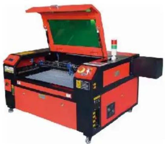
4. UNPACK THE ENGRAVING MACHINE.
- Your engraver comes in a wooden case with its accessories (including this manual) packed in the area behind the front door. You should place the crate in a generous, flat area for unpacking, and plan to operate the machine permanently.
- Step 1: If you haven't already done so, finish removing the crate from around the engraver. Then roll the machine into place.
- Step 2: Hold the brake pads in place by pressing the brake pads on the front wheels.
- Step 3: Retrieve the access key from the main bay at the front of the machine. Remove the accessory bag from the area behind the front door. Check that you have received all of the following items: power cord, ground cable, USB and Ethernet cables, USB flash drive with engraving software, exhaust pipe with hose clamp, set of hex wrenches, acrylic focusing tool, keys, and this manual.
- Step 4: Carefully inspect the assembly of the laser tube, the view window, and the rest of the machine. The laser tube is a highly fragile object and should be handled with care and as few bumps as possible.
- Step 5: Inside the main bracket, remove the X-axis and the honeycomb table.
- Step 6: You can keep the packaging for future returns, but if you dispose of it or any accessories, be sure to follow the applicable waste disposal regulations.
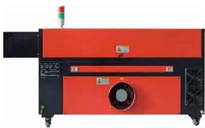
5. MAIN POWER CONNECTION.
- Confirm that the label next to the connected outlet on the machine matches your power supply. Connect one end of the main cable to the connection socket and the other end to a grounding socket. Under no circumstances should you turn on the device if the voltage does not match.
correspond.
- Fluctuations along the line should be less than 10%. If this value is exceeded, the fuse will blow. They are located in the connecting socket and are externally accessible. Again, do not connect this device to a standard extension cord or power strip. Connect it directly to a grounded outlet or use a surge protective device rated over 2000J.
6. WATER-COOLED INSTALLATION.
- The supplied water pump is critical to the performance and service life of the engraving machine. When such a laser works without a properly maintained cooling system, its glass tube can explode due to overheating.
- Never touch or adjust the water supply of the engraving machine while the pump is plugged in.
- To use the water pump, fill a dedicated tank with at least 2 gallons (7.5 liters) of distilled or purified water. This will gradually reduce the quality of the engraving machine and may even lead to dangerous mineral accumulation in the cooling system. For the same reason, never use all-purpose antifreeze. Use custom laser-safe formulations or store engraving machines in climate-controlled areas.
Note: Distilled water or purified water must be added, not tap water or sewage, otherwise it will reduce the service life of the product.
- Please rotate to remove the dust cover of the water inlet, and then add purified water or distilled water to the water inlet for the engraving machine. The green range of the water level line is the safe water level. Then you can replace the water nozzle dust cover, and then turn on
the main power supply and water circulation switch of the machine.
Note: The water level should not be too full, so as not to overflow the water cooler.
Water inlet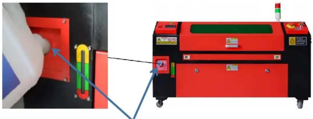
- Before starting the laser, be sure to obtain visual confirmation that water is flowing through the laser tube.
- Never let the water in the tank become too hot to cool the laser. Use a heat alarm or check the water temperature regularly during extended use. If the water starts to reach 100°F (38°C), replace it with cool water. During this process, either the laser is replaced in phases or the laser is turned off: never allow the laser to operate without a continuous flow of cooling water.
7. INITIAL TESTING.
- EMERGENCY SHUTDOWN.
Due to the risk of fire and other hazards during the engraving process, the engraving machine includes a large, easy-to-reach emergency stop button
near the control panel. Press it to stop the laser tube immediately.
When your engraver arrives, its emergency stop has been pressed and must be rotated to the right and bounce upwards for the laser to work. Before using the machine for any other work, you should test if it is properly. Start the water cooling system, place a piece of laserable material on the work bed, close the lid, and press PULSE to fire the laser. Press the emergency stop button and observe if the laser stops immediately. If the laser continues to fire, the emergency stop does not work and must be replaced before using the engraver. Turn off the machine and contact customer service.
Due to the risk of blindness, burns, and other injuries from direct exposure to the invisible engraving beam, the device
also automatically shuts off the laser when the protective cover is raised during operation.
After making sure that the emergency stop button is working properly, you should also test that the cover closure is working properly before doing any other work on the machine. Start the water cooling system, place a laserable scrap on the work bed, close the lid, and press PULSE to fire the laser. Release the button. Be careful not to expose yourself to any possible reflected lasers, open the lid as little as possible and try the laser again.
Note: If the laser is emitted, the automatic shut-off does not work and must be repaired before using the engraver. Turn off the machine and contact customer service.
WATER CUT-OFF.
Due to the dangers posed by uncooled laser tubes, the engraver also automatically shuts down the laser when the water cooling system fails. After making sure that both the emergency stop button and the lid protection
are working properly, you should also test that the water cut-off is working properly before doing any other work on the machine. Start the water cooling system, place a piece of laserable scrap on the work bed, close the lid, press PULSE to fire the laser. Release the button. Cut off the flow of water by curling or tying two hoses. Be careful not to damage the hose itself during the process. Try firing the laser again. If the laser is emitted, the automatic shut-off does not work and must be repaired before using the engraver. Turn off the machine and contact customer service. If the laser does not emit, the automatic shut-off works fine; simply loosen both hoses to start circulating water again and continue setting up the engraver.
While our factory calibrates your entire system during assembly, the laser focusing lens, and/or one or more mirrors may be pushed out of alignment during shipping. Therefore, it is recommended that you perform an optical alignment test when setting up your machine. For step-by-step guidance, see the maintenance section below.
AIR ASSISTED.
Your air auxiliary equipment should be pre-installed and properly wired. Just check if it is properly configured and connected as shown in the image. If pipes or wiring need to be reconnected, turn off all power to the machine
(including pressing the emergency stop) before adjusting any equipment.
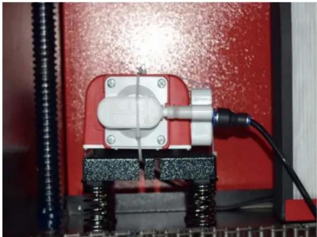
8. SECURITY.
For your own safety and the safety of passers-by, this engraving machine can be locked with the key provided. It is recommended that you use it to lock your computer between sessions to prevent any unauthorized actions on your computer.
OPERATION
1. OPERATION OVERVIEW.
- Operate this laser engraver only by following all the instructions provided in this
manual. Failure to follow the appropriate guidelines detailed herein may result in property damage and personal injury.
- This section will describe only some of the options and features offered by the operating software. Before you start using the machine, make sure you have read the entire manual (especially the safety information above), as well as any and all warnings provided by the machine itself.
2. GENERAL OPERATING INSTRUCTIONS.
- Step 1. Create the design you want to engrave. You can do this directly in the engraving software, or you can use any
- Step 2. Please connect the companion equipment and tools to the product and connect the power supply. You can refer to the video on CD/USB. Fill the water inlet with purified or distilled water for the built-in water circulation. The water level must be added to the green water level safety line. Note: (The water level should not be too full, so as not to overflow).
- Step 3. Please remove the smoke pipe. One end of the smoke pipe is connected to the smoke exhaust port of the equipment, and the other end is connected to an outdoor or auxiliary smoke extraction device. Note: (Please use a tube clamp to secure the connection to prevent it from falling off.)
- Step 4. Pull up the emergency stop button and use the buttons on the front of the cabinet to open the control panel of the engraving machine. Load the design of your choice directly from a USB flash drive or via a computer's connection to the engraver.
- Step 5. Open the engraver cover, check that the air assist is working properly, and adjust the table if necessary. Cellular beds are recommended for most applications. The bed can be raised or lowered using the Z-axis control on the front of the cabinet to accommodate a variety of materials of different thicknesses.
- Step 6. Place the material sample on the bench. The standard position is located in the upper left corner of the table. This can be changed by moving the location of your design or engraver's origin using the control panel or engraving software. To handle larger materials, you can open the front or rear through door, or both, at the same time. When the laser is active, do not insert anything into the work surface through a pass-through door other than the material. Pay special attention to fumes and dust that may be released through these doors. Make sure your ventilation system is robust enough to absorb all by-products or wear the necessary PPE to ensure the health of users and passers-by.
- Step 7. Focus the laser by placing the acrylic focusing tool on top of the material and carefully lifting the table. The laser head should barely touch the top of the acrylic tool without applying any pressure, ensuring that the engraving distance is correct. (Again, never try to be on the bench without material.) In any way, the laser is focused. Close the lid.
- Step 8. Customize the contrast and engraving depth of your design by adjusting parameters in the engraving software or directly from the control panel. If your engraving instructions detail the power setting in milliamps, use the following conversion chart to find the appropriate power setting:
| right | 20% | 30% | 40% | 50% | 70% | 80% | 90% | 99% |
| current | 4ma | 4ma | 7ma | 9ma | 14ma | 16ma | 18ma | 19ma |
The minimum threshold is 10%. The laser will not be emitted at any setting lower than this setting. It is not recommended to use the laser tube at full load, especially for long periods of time. The recommended maximum power is set at 70%, as
prolonged use of more than this amount will shorten the lifetime of the laser. To increase the engraving depth, increase the energy per unit area by increasing the laser's power or number of rings or slowing down the speed parameter. However, engraving too deep can degrade the image quality, especially for the coating material.
When working with new materials, keep in mind that you should always start at the low end of your possible settings. If the effect is not strong enough, it can always be more than once Rerun the design loop, or rerun it with more powerful settings until you create the desired effect.
The resolution should generally be set to 500 dots per inch. In some cases, lowering the image resolution may help, reducing burn and Increase the energy of the pulses and thus improve the quality of the images produced in certain materials, such as certain plastics.
- Step 9. Open the laser tube by inserting and turning the laser key. To reduce the risk of electric shock, try touching the engraver with only one hand at a time once the laser tube is opened.
- Step 10. Press run to pause to engrave your design. Similarly, even if you are wearing protective glasses, do not stare at the active laser continuously. However, be aware of possible issues such as sparks or fires, and be prepared to extinguish fires quickly if necessary.
- Step 11. Once the laser stops, check the quality of the first run and adjust the laser parameters in the control panel or software as needed to produce the desired effect. During repeated engraving and cutting, check the pump's tank regularly to keep the water temperature below 100°F (38°C). If this temperature is reached, stop working and allow the engraver to cool down before further use.
- Step 12. When you are done engraving, close the engraving software and turn off the machine in the following order: laser power, control panel, any ventilation, water cooling system, and emergency power button. Remove the laser key from
the control panel.
Step 13. Clean the bench completely, emptying the lower bracket of any debris.
3. SPECIFIC MATERIAL DESCRIPTIONS.
The following instructions are recommendations that can help expedite safe work with a variety of materials. Users should research the safety and engraving requirements for their specific materials to avoid the risk of potential problems such as fire, hazardous dust, corrosive and toxic fumes. Once you know that the product is safe or with the proper protective equipment in place, it can be helpful to engrave a test matrix of small boxes produced at various speeds and power settings to discover the ideal settings for your design. Or start with low power consumption and fast setup, re-run the design as many times as needed, using progressively increasing laser intensity.
CERAMICS.
When engraving on ceramics, medium to high power is generally used. Using more circuits instead of higher power and lower speed can help avoid material breakage during the working process. Be aware of the health risks posed by dust from ceramic engraving, especially for repetitive industrial applications. Depending on the material and workload, a fan or even a complete ventilation system may be required to resolve the issue. Similarly, operators and others in the work area may need to use respiratory PPE, such as masks and respirators.
STONE.
When carving all kinds of stones, medium power and medium to fast speeds are generally used. As with ceramics and glass, be aware of the dust generated (especially for repetitive industrial applications) and take similar measures to ensure the safety of users and others in the work area.
TEXTILES.
When it comes to carving textiles such as cloth and wool, low power and high speed are often used. As with leather, special attention should be paid to the possibility of
fire and dust.
GLASS.
When engraving glass, high power and low speed are generally used. As with ceramics, it would be helpful to run more cycles on a lower setting to avoid cracks. Care must be taken when engraving glass and carbon fibers to avoid combining settings that produce laser intensity sufficient to disrupt the structural integrity of the fibers or their components, resulting in blurred markings. Personal protective equipment should be worn to avoid exposure of eyes, nose, mouth, and skin to dust from the use of any kind of material, especially for repetitive industrial applications. Clothes worn when working with fiberglass should be washed separately afterwards.
LEATHER.
When engraving glass, high power and low speed are generally used. As with ceramic, it would be helpful to run more cycles on a lower setting to avoid cracks. Care must be taken when engraving glass and carbon fibers to avoid combining settings that produce laser intensity sufficient to disrupt the structural integrity of the fibers or their components, resulting in blurred markings. Personal protective equipment should be worn to avoid exposure of eyes, nose, mouth, and skin to dust from the use of any kind of material, especially for repetitive industrial applications. Clothes worn when working with fiberglass should be washed separately afterwards.
CO2 laser engraving machines should not be used to mark, engrave, or cut metal. They are best suited for working coatings applied to metal substrates, and care must be taken not to attempt to work on the underlying metal itself. A variety of coatings are available specifically for CO2 engraving, and users should follow the instructions provided as the parameters vary depending on the product and the metal. In general, the work on aluminum coating should be done faster at a lower power, while the work on steel coating can be done more slowly at a higher power.
PLASTICS.
The plastic used for engraving comes in many different colors and thicknesses and has many different coatings and finishes. Most of the plastics available can be
engraved and cut well with lasers. Plastics with microporous surfaces seem to provide the best results because less surface material needs to be removed. When engraving plastics, low-power, high-speed settings are generally used. Marking and engraving with too much power or too low a speed can concentrate too much energy at the point of contact, causing the plastic to melt. Among other problems, this can produce poor carving quality, toxic fumes, and even fires. High-resolution engraving can cause the same problem, so low- to medium-resolution designs should be preferred for most plastics.
RUBBER.
The various compositions and densities of the rubber result in slightly different engraving depths. It is highly recommended to test samples of specific rubber for best results. When engraving rubber, a consistent high-power setting is often used, and the effect is created by varying the speed of the laser. Microcellular rubber materials require much higher speeds than standard rubber. Engraving any type of rubber produces a lot of dust and gases. Depending on the workload, breathing PPE and/or a complete ventilation system may be required to resolve the issue.
PAPER AND CARDBOARD.
When engraving a variety of paper products, low to medium power and fast speed are generally used. Test samples per batch, as only small parameter differences can distinguish the effect of being too light from the effect of burning through the substrate. As with leather, special attention is paid to the possibility of fire, as well as dust generated during repeated applications.
- TIMBER.
As with rubber, there are many different types of wood, and testing your specific material is essential to get the best results. In general, wood carvings with consistent
Grain and color are more uniform. Knotted wood creates an uneven effect, while resin wood creates greater edge contrast. Some softwoods, such as balsa, cork, and pine, carve well (albeit with low contrast) at low or medium power settings and at high speeds. Other fibers like fir can be affected by uneven fibers and will often produce poor results no matter what you do. Hardwoods such as cherry and oak carve well at high power settings and low speeds. Artificial wood products can vary from brand to brand, mainly based on their glue composition and abundance. MDF works well but creates dark edges when cut.
In addition to the fire risk of any wood product, extra care must be taken with SMC from glue used in plywood and other artificial wood. Some are too dangerous to use at all, while others require careful ventilation and repetitive industrial applications using breathable PPE. Wood toxicity should also be checked, as dust from some natural woods, including oleander and yew, can also cause enough nausea and heart problems.
| material | thickness | 50W | 60W | 80W | 100W | 130W | 150W |
| Fastest speed | Optimal speed | Fastest speed | Optimal speed | Fastest speed | Optimal speed | Fastest speed | Optimal speed | Fastest speed | Optimal speed | Fastest speed | Optimal speed |
| acrylic acid | 3mm | 15/S | 10S | 20S | 15S | 25/S | 20/S | 30S | 25S | 35/S | 30S | 40/S | 35S |
| 5mm | 8S | 5S | 10S | 7/S | 12/S | 8S | 15/S | 10S | 17/S | 12/S | 21/S | 15/S |
| 8mm | 4S | 2S | 5S | 3/S | 9/S | 5S | 10S | 6S | 12/S | 8S | 15S | 10S |
| 10mm | | | 4S | 2/S | 6/S | 3S | 7/S | 4S | 8/S | 5S | 11/S | 7S |
| 15mm | | | | | 3/S | 1S | 4S | 2S | 5/S | 3S | 7/S | 4S |
| 20mm | | | | | | | | | 3/S | 1/S | 4S | 1.5/S |
| 25mm | | | | | | | | | | | | |
| 30mm | | | | | | | | | | | | |
| Laser power 90%: Acrylic cutting should pay attention to air flow control, the surface of the material blowing should be small or side-blowing, which can ensure the smoothness of acrylic, and the acrylic surface should have air circulation to prevent fire |
| Acrylic | 3mm | 9/S | 7/S | 15/S | 12S | 20/S | 15S | 23S | 18/S | 25/S | 20S | 30S | 25/S |
| 5mm | 5/S | 3S | 10S | 8/S | 13/S | 10S | 15S | 13/5 | 18/S | 15/S | 21/S | 18/S |
| 10mm | | | | | 5/S | 3S | 7/S | 5S | 9S | 6S | 12S | 9/S |
| 15mm | | | | | | | | | 4S | 3/S | 7/S | 5/S |
| Laser power 90: Wood cutting mainly controls the airflow, the larger the airflow, the faster the cutting speed |
| PVC | 2mm | 35/S | 32/S | 50S | 45S | 60/S | 58/S | 70S | 68/S | 80/S | 78/S | 90S | 88/S |
| 3mm | 30/S | 27S | 40/S | 38S | 50/S | 48/S | 60S | 58/S | O/S | 68/S | 80S | 7a/S |
| 4mm | 25/S | 20S | 35/S | 30S | 45/S | 40S | 55S | 50/S | 65/S | 63/S | 75S | 7/S |
| cloth | a bed | 40/S | 38/S | 60/S | 58S | 100/S | 98/S | 200S | 195S | 300/S | 295/S | 400S | 395S |
| leather | a bed | 15/S | 12/S | 20/S | 17/S | 25/S | 20/S | 30S | 25/S | 40/S | 35/S | 45S | 40/S |
| It is recommended to use a focusing lens with a focal length of 50.8,with a laser tube of 60W-100W and a sma amount of air compressor,it is recommended to cut at 50%-70%power. |
| Paper | monctayer | 80/S | 40S | 120S | 40S | 150/S | 40/S | 250S | 40/S | 350/S | 40/S | 450S | 40/S |
| Bi-color or stab | 2mm | 15/S | 13S | 25S | 20S | 36/S | 30S | 40S | 35/S | 45S | 40S | 55S | 50/S |
| Bi-color plate and PVC cutting parameters,paper-cutting should pay attention to laser power adjustment,the higher the laser tube power,the smaller the percentage of laser power adjustment |
OVERVIEW.
You can control the engraver directly from the built-in control panel, connected to a computer, or via the Internet. For more information on operating the engraving software, please refer to its separate manual. The built-in control panel allows the laser to be operated manually, or the design can be engraved onto flash drives and external hard drives connected to the USB port on the right side of the cabinet.
You can control the engraver directly from the built-in control panel, from a computer, or via the Internet. For more information on operating the engraving software, please refer to its separate manual. The built-in control panel allows the laser to be operated manually, or the design can be engraved onto flash drives and external hard drives connected to the USB port on the right side of the cabinet.
To load a design from a FAT16 or FAT32 formatted flash drive or external hard drive, press MENU, select "File", then "Udisk+", and then "Copy to Memory". Select the design in the File menu, and then select Run. Parameters can be adjusted using the console's menus and submenus, including setting multiple origins to engrave a design on a material multiple times in a single session.
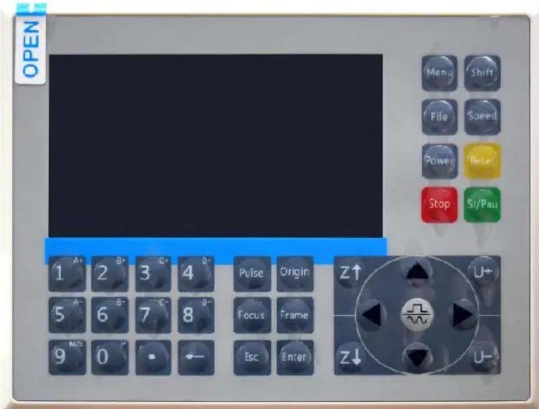
To load a design from a FAT16 or FAT32 formatted flash drive or hard drive, press MENU, select "File", then "Udisk+", and then "Copy".
Memory". Select the design in the File menu, and then select Run. Parameters can be adjusted using the console's menus and submenus, including setting multiple origins to engrave a design on a material multiple times in a single session.
When running the design from the console, this will be the main display. The design should be displayed in the upper left corner, and its name along with the current speed and power settings should be displayed in the upper right corner. The position of the laser head relative to the shown as X (horizontal) and Y (vertical) coordinates. The Z-coordinate shows the elevation of the workbench itself. The U-coordinate can be configured to control the axis of rotation or automatic feeding, if installed. Below them are layers that contain instructions about their individual speeds (in mm/s) and maximum power as a percentage of the machine's rated power. The number of batches in the lower left corner records the number of times the current design has been engraved in a single session.
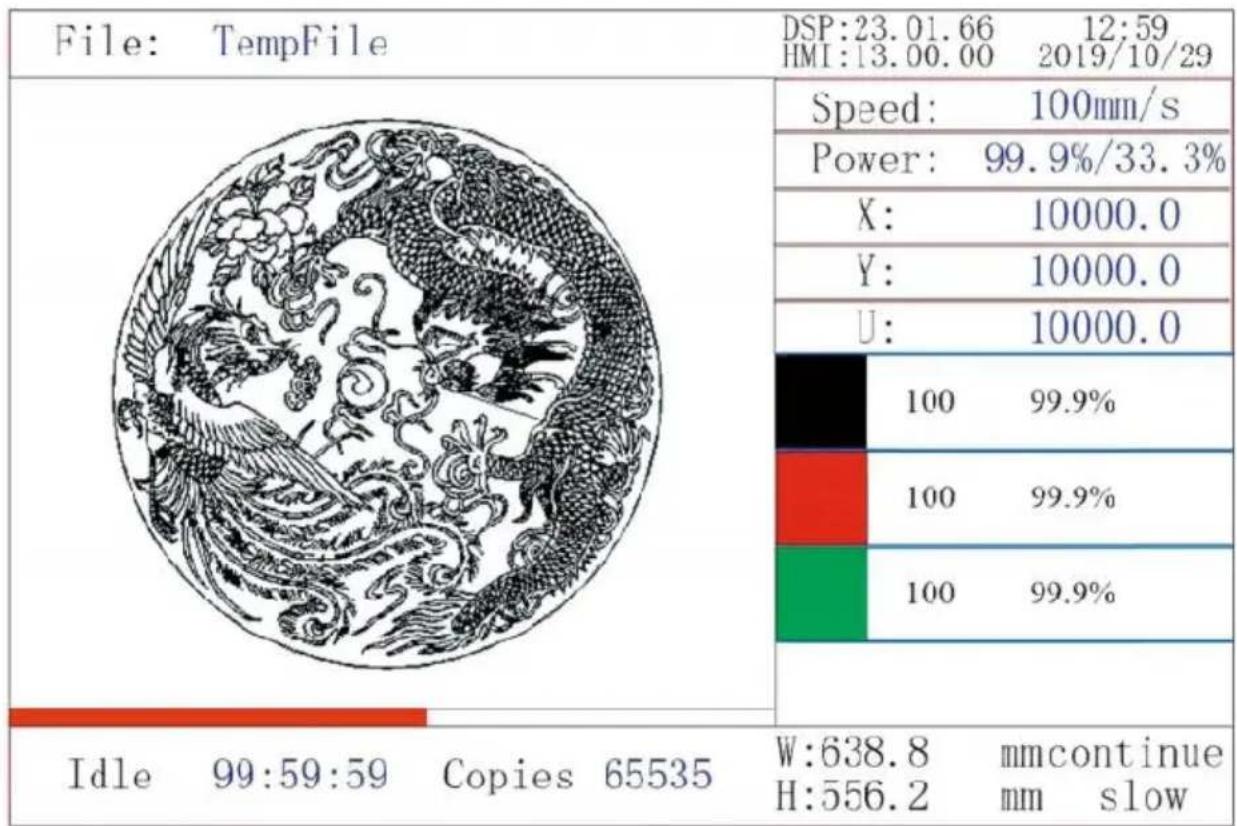
Just like the button says, press Run/Pause to start engraving the loaded pattern and pause the engraving when needed.
In the event of an emergency such as fire, do not use the control pause or stop engraving. Press the emergency stop button immediately.
When you press ENT in the main interface, the cursor box initially sets the "Speed" parameter.
| Speed | 100mm/s |
| Power: | 99.9%/33.3% |
| X: | 10000.0 |
| Y: | 10000.0 |
| U: | 10000.0 |
Press the ▲ and ▼ keys to switch between parameters. Select the Power parameter.
| Speed: | 100mm/s |
| Power | 99.9%/33.3% |
| X: | 10000.0 |
| Y: | 10000.0 |
| U: | 10000.0 |
Press ENT when the red cursor is over Power. Press the ▲ and ▼ keys to change the parameter value.
MaxPower: 99.9 %
MinPower: 33.3 %
Press ENT to save your changes.
Press ESC to invalidate the changes and go back to the main interface.
SET THE LASER SPEED
When you press ENT in the main interface, the cursor box initially selects the "Speed" parameter.
| Speed | 100mm/s |
| Power: | 99.9%/33.3% |
| X: | 10000.0 |
| Y: | 10000.0 |
| U: | 10000.0 |
Press the ENT key again to bring up this interface.
Press the ▲ and ▼ keys to change the parameter value.
Press ENT to save your changes.
Press ESC to invalidate the changes and go back to the main interface.
Speed: 100 mm/s
FUNCTION MENU.
Press the menu on the main interface to enter the menu interface:
Press the ▲ and ▼ keys to select the item, and then press ENT to enter the corresponding submenu.
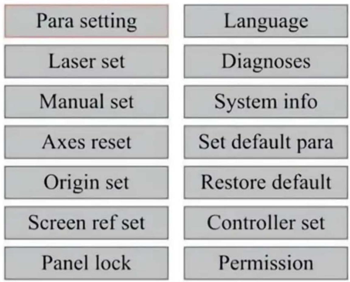
When Z Move is selected, press ◀ or ▶ to control the movement of the Z axis while the sensor kit is installed.
When U Move is selected, press ◀ or ▶ to control the movement of the U axis. This can be used to control the rotational position of the axis rotation or the linearity of the automatic feed (positions are sold separately, both installation).
When Shaft Reset+ is selected, press ENT, and the left display will show: Push ▲ or ▼ to select an item.
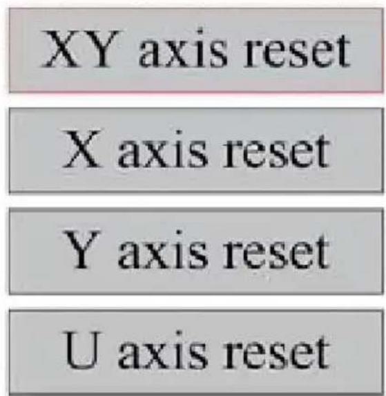
Press ENT to start resetting the selected axis and the message "Res progress" will appear on the screen.
When it is done, the message will disappear automatically and the system will return to the main interface.
- ADJUST THE LASER SETTINGS.
After selecting the laser settings and pressing ENT, the left display will show: The operation method is the same as the previous setting. When selecting Continue, press PULSE to fire the laser, and then release to complete the firing. When you're done making adjustments, save them by selecting the ENT key to write or pressing the ESC key to leave without saving the changes. Reading can load saved parameters.
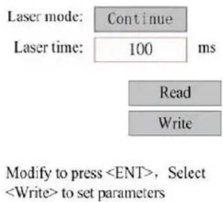
- ADJUST THE LASER MOVEMENT MODE.
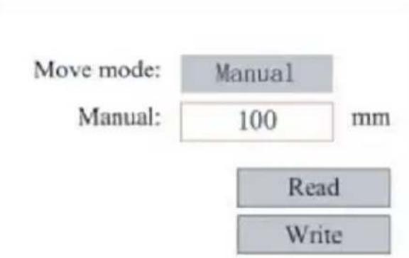
When you select Manual Settings, press ENT, and the left side will be displayed: When the movement mode is "Continuous", the manual jog parameter does not work. When used to manually move the laser, the arrow keys move it continuously until released. When the movement mode is "Jog", each time the arrow keys are pressed, the laser head moves precisely the distance saved in this parameter. Use the Direction and ENT keys to adjust up or down. When you're done making adjustments, save them by selecting the ENT key to write or pressing the ESC key to leave without saving the changes. Reading can load saved parameters.
When the box is pressed on the origin set, press ENT, and the left box will pop up:
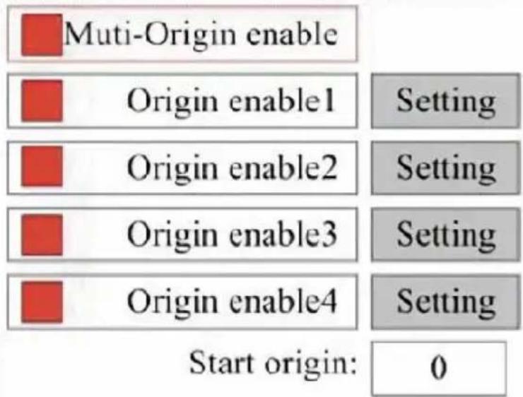
Press FN to select an item. After selecting Multi-Source Enable, press to enable or disable the item. When enabled, the small box will be checked; when disabled, the small box will be gray. When you select Set Origin or Next Origin, press ◀ or ▶ to select a value. When changing the Set Origin parameter, remember to press ENT to verify the change. When closing the interface, the parameters are automatically saved.
The details of each item are as follows:
- Set Origin 1/2/3/4: After enabling the multi-origin setting, place the cover setting to Origin 1/2/3/4. Press ENTER on your keyboard key, the system takes the coordinates as the corresponding coordinate for origin 1/2/3/4.
- Source Enable 1/2/3/4: When the multi-source setting is enabled, four sources can also be disabled and enabled individually.
When multi-origin logic is selected, if the number of the next origin is four origins are enabled, the work will be used every time it is started. The save file function is started (via keyboard or PC) or when a profile is uploaded to a PC and the file is selected "Take origin as origin".
Different origins. The order of rotation of the origin is 1 → 2 → 3 → 4 → 1 → 2 …
If you upload a processing file to your PC and you select Current C
the file, the system will always use the current origin.
When the facts are set, select the paragraph and the machine's current parameters will be stored as their default values. They can then be retrieved using the Restore Default Parameters command. It is recommended that you save the actual factory default settings of your machine so that it can be easily restored if needed.
If the password is enabled, push ◀ or ▶ and ▲ or ▼ to select password, and then press ENT to save the password.
RESTORE THE DEFAULT PARAMETER.
When defining facts, once a parameter is selected, the system replaces current parameters with the saved default factory parameters. The operation method is the same as setting the default parameters.
- SET THE INTERFACE LANGUAGE.
When selecting a language, press ENT and the left display will show
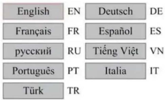
The operation method is the same as above. Press ENT after selecting the desired language and return to the main interface.
- SET THE IP ADDRESS OF THE MACHINE.
Once you have selected your IP settings, press ENT and the left display will show:
IP address:

Write
Push ◀ or ▶ and ▲ or ▼ and ENT to change the parameters.
Default address for the engraver is 192.168.1.100. If this feature is being used on your local network, use 192.168.1 for the first three segments and choose a unique value for the last part. In general, any value between 2 and 252 should be fine except for 47, but avoid values that are already used by other networked devices.
Connecting the machine directly to the public internet carries the risk of unauthorized use and is not recommended. If you still wish to provide access, you'll need to register and use a unique public TCP/IP address. When you're done making adjustments, save them by selecting the ENT key to write or pressing the ESC key to leave without saving the changes. Reading can load saved parameters.
DIAGNOSTIC TOOLS.
After selecting Diagnostics, the left dialog box will pop up:
INPUT:

LmtX-

LmtU+

WP

LmtY-

LmtU-

Inl

Ex-Run

Intlock

In2
OUTPUT:

OUT1

OUT2

Status

Aux.Air
This interface displays the system's hardware I/O port information:
Input: Read the hardware information of the system. When a hardware signal is triggered, the small box to the left of the corresponding entry will be shown in red. Otherwise, it will be grayed out.
Output: Use the cursor to select the output. Press ENT to toggle the state, and ESC to return to the main menu without making any changes.
- SETTING THE SCREEN REFERENCE.
After selecting the Screen Origin, the left dialog box will pop up:
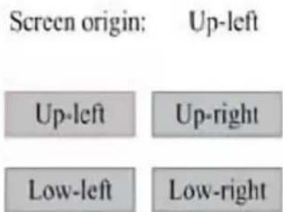
This interface displays the location of the origin. Different origin positions can produce different reflections of the graph on the X/Y axis. The operation method is the same as above.
- ADJUSTING THE SCULPT LAYER.
When the system is idle or the work is complete, press ENT to enter layer parameters section.
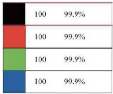
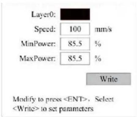
Press or to select the desired layer.
Press ENT to check the parameters of the selected layer, as shown in the image: By default, the red cursor will be over Layers.
Press the and keys to select the desired layer.
Move the cursor to Write and press ENT to save the parameter changes, or press ESC to exit without saving.
The method of operation is the same as the maximum/minimum power setting.
- ADJUST MOVEMENT PARAMETERS.
In the Parameter Settings submenu, select Move Parameters to display the left interface: Select and adjust parameters by pressing the arrows.
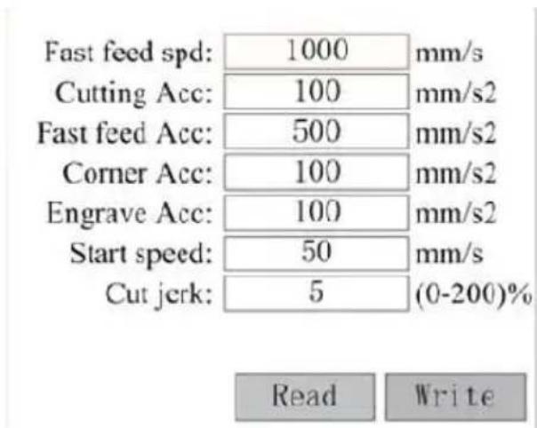
When you're done adjusting, move the cursor to Write and press ENTER to save the parameter changes, or press ESC to exit without saving. Reading can load saved parameters.
Save the parameter changes, or press ESC to exit without saving. Reading can load saved parameters.
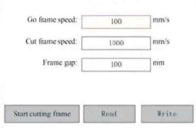
In the Parameter Settings submenu, select Frame Settings to display the left interface: Select and adjust parameters by pressing the arrows. When you're done adjusting, move the cursor to Write and press ENTER to save parameter changes, or press ESC to exit without saving. Reading can load saved parameters. Start Cutting Frame will cut the frame according to current parameters.
In the Para Settings submenu, select Frame Settings to display the interface. Select and adjust parameters by pressing the arrows. When you're done adjusting, move the cursor to Write and press ENT to save parameter changes, or press ESC to exit without saving. Reading can use saved parameters. Start Cutting Frame will cut the frame according to current parameters.
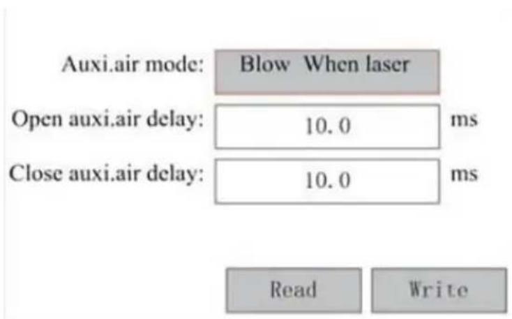
In the Parameter Settings submenu, select Blow Settings to display the interface: Select and adjust parameters by pressing the arrows. When you're done adjusting, move the cursor to Write and press ENTER to save parameter changes, or press ESC to exit without saving. Reading can load saved parameters.
In the Paragraph Settings submenu, select Blow Settings to display the interface. Select and adjust parameters by pressing the arrows. When you're done adjusting, move the cursor to Write and press ENT to save parameter changes, or press ESC to exit without saving. Reading can save parameters.
- In the "Parameter Settings" submenu, select "Speed Settings" to display the left interface:
In the "Parameter Settings" submenu, select "Speed Settings" to display the left interface:
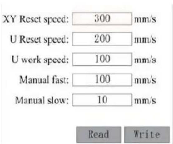
Select and adjust parameters by pressing the arrows. When you're done adjusting, move the cursor to Write and press ENT to save the paragraph changes, or press ESC to exit without saving. Reading can load saved parameters.
- In the Parameter Settings submenu, select Computer Configuration to display the left interface:
In the Parameter Settings submenu, select Computer Configuration to display the left interface:
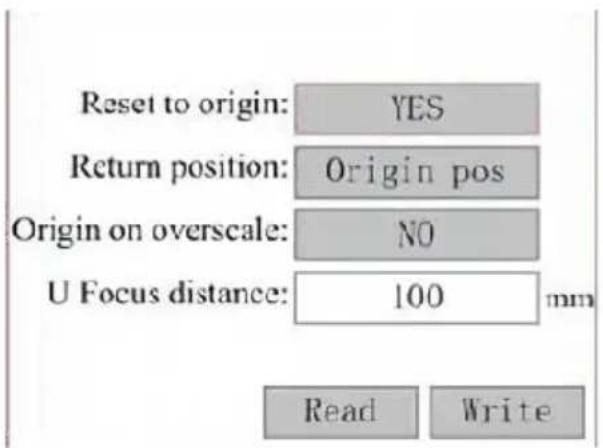
Select and adjust parameters by pressing the arrows. When you're done adjusting, move the cursor to Write and press ENT to save the parameter changes, or press ESC to exit without saving. Reading can load saved parameters.
- ADJUST THE PARAMETERS OF THE AXIS OF ROTATION.
In the Parameter Settings submenu, select Rotation Function Settings to display the interface on the left:
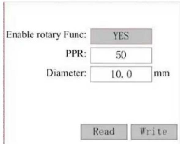
Select and adjust parameters by pressing the arrows. When you're done adjusting, move the cursor to Write and press ENT to save the parameter changes, or press ESC to exit without saving. Reading can load saved parameters.
- SET THE INTERFACE PASSWORD.
When the cursor is on the panel lock, press ENT, and the dialog on the left pops up:
Password Set
Keyboard locked
Press the and keys to select the item. When the blue cursor is over the target item, press ENT to enter the corresponding interface.
- BACKUP AND RESTORE PARAMETERS.
In the main menu, select Controller Settings to display the left screw
Backup to U disk
Back up to USB flash drive: Save the current parameters to a USB drive.
Recover Parameters from USB Flash Drive: Recover saved parameters from a flash drive.
Upgrade from USB flash drive: Upgrade the controller software from a flash drive.
- SET THE DATE AND TIME OF THE MACHINE.
In the Controller Settings submenu, select Time Settings+ to display tI
left interface:
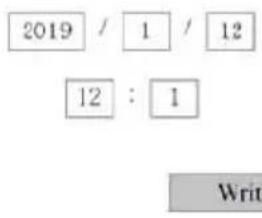
Modify to press ,Select to set parameters
Select and adjust parameters by pressing the arrows. When you're done adjusting, move the cursor to Write and press ENT to save the paragraph changes, or press ESC to exit without saving. Reading can load saved parameters.
AUTHORIZATION MANAGEMENT AND KEYBOARD LAYOUT.
Your engraver should already be authorized and ready to go. If you purchased your engraver through a rental program and have not yet received a license code, please contact Customer Service. Enter it by going to the main menu and selecting Permissions. The left interface pops up.
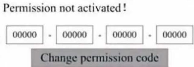
Press ENT once to select the first field, and then press ENT again up the left keyboard.
Use the arrow keys and ENT to select the right characters. If there are errors, press ESC and then ENT to re-enter the field. Use the arrow to move to a different input field and enter its contents in the same way. Once all the fields have been entered correctly, select Change Permission (C) and press ENT to leave this screen and return to the main menu.
MAINTENANCE
Use of procedures other than those specified herein may result in dangerous exposure to laser radiation. Always turn off the appliance and disconnect it from the power supply before performing any cleaning or maintenance work. Always keep the system clean, as flammable debris, the work and exhaust areas pose a fire hazard. Only trained and self-professionals are permitted to modify or disassemble this equipment.
- Clean and cool water must be supplied to the system at all times
The workbench must be cleaned and the bin emptied every day.
- The third mirror and focusing lens must be inspected daily and cleaned if needed.
- Other mirrors and exhaust systems must be inspected weekly and cleaned if needed.
- Beam alignment should be checked weekly.
- The wiring should be checked weekly for loose connections, especially for the laser tube power supply.
- The rails should be cleaned and lubricated at least twice a month.
- Air assistance must be inspected once a month and cleaned if needed.
- The entire laser machine, including other components such as the water cooling system, must be inspected once a month and cleaned if needed.
2. Water Cooling System.
- Never touch or adjust the engraver's water supply while the pump is connected to power.
- The laser tube needs to be cooled with clean distilled water to avoid overheating. Room temperature or slightly lower warm water is ideal. Laser tubes require at least 2 gallons (7.5 liters) of cooled clean distilled water or other laser-safe coolant to avoid overheating. If the water
temperature is close to 100°F (38°C), stop working until it cools down or find a way to lower its temperature without interrupting the tube's water supply. The water should also not get too cold, which could cause the glass laser tube to shatter during use. In the winter months or if using ice to cool hot water, make sure the temperature never drops below 50°F (10°C).
- More water should be added every few days to ensure that evaporation does not cause the pump to be exposed during use.
3. CLEANING
- CLEAN THE MAIN COMPARTMENT AND ENGRAVING MACHINE.
Check at least once a day for dust accumulation in the main engraver chamber. If dust is present, remove it. The exact cleaning intervals and requirements depend heavily on the material being processed and the operating time of the equipment. Clean machines ensure optimal performance, reduce service costs, and reduce the
risk of fire or injury.
Clean the viewing window with a mild detergent and a lens cloth or cotton cloth. Do not use paper towels, as they can scratch the acrylic and compromise the lid's ability to protect you from laser radiation. Clean the interior of the main cabin thoroughly to remove any debris, particles, or sediment. Paper towels and window cleaners are recommended. If necessary, clean the laser tube after it has cooled completely. Allow any cleaning liquid to dry completely before using the engraver further.
The lens has a durable coating that will not be damaged by proper careful cleaning.
You should check the lens and mirrors on the third day and clean them if there is any debris or haze on the surface. Your laser efficiency will be reduced, and heat build-up on oil or dust itself can damage the lens.
- Move the engraving table to a distance of about 4 inches (10 cm) below the lens mount.
- Move the laser head to the center of the table and place a cloth under the lens mount so that the lens will not be damaged if it accidentally falls off the mount.
- Unscrew the lens mount and rotate it to the left.
- Remove the pressurized air hose and laser rail connection.
- After placing the lens on clean lens cleaning paper, carefully turn the lens holder so that the lens and its O-ring fall onto the cleaning cloth to remove the lens from the lens mount.
- Check the O-ring and, if necessary, clean it with a cotton swab, lens cleaning paper, towel, or cloth.
- Blow air onto the surface of the lens to remove as much coarse dirt as possible.
- Inspect the lens surface and clean the lens with lens cleaning solution and lens paper or cloth if necessary.
- Hold the edge of the lens assembly with a lens cleaning tissue and use lens cleaning solution. Hold the lens at an angle and rinse both
surfaces to wash away the dirt.
- Place the lenses on a clean lens cleaning tissue and apply some lens cleaning solution to one side of the lens. Allow the liquid to be effective for about a minute, then gently wipe with lens cleaning paper dipped in lens cleaning solution. Dry this side of the lens with a clean cloth.
- Repeat the same cleaning process on the other side of the lens. Never use cleaning paper towels twice. Dust that accumulates in cleaning paper towels may scratch the surface of the lens.
- Check the lens. If it is still dirty, repeat the cleaning process until the lens is clean. Do not touch the surface of the lens after
- Carefully insert the lens into the lens mount, making sure its convex side is facing up. Place the o-ring on top of the lens.
- Carefully reassemble the lens and laser head attachment in reverse order.
CLEAN THE MIRROR.
If there is any debris or haze on the surface of the mirror, the mirror should be cleaned as well to improve performance and avoid permanent damage. The first mirror is located behind the left side of the machine, beyond the end of the Y-axis. The second mirror is on the Y-axis at the left end. The third mirror is located on top of the laser head on the X-axis. The largest accumulation of debris is on the 3rd mirror and should be checked daily with the focusing lens. The first and second mirrors can be checked daily if needed, but if they are only checked once a week, they are usually fine.
1st mirror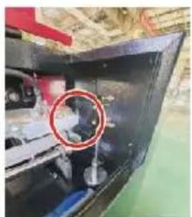
2nd mirror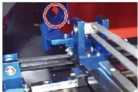
3rd mirror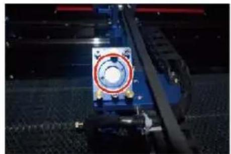
Mirrors can be cleaned in place using lens cleaning tissues or cloths. They can be removed by rotating them counterclockwise. Be careful not to touch the surface of the mirror directly. Avoid pressing too hard to remove debris and cause scratches. If the mirrors are removed for cleaning, reinstall them by rotating them clockwise into place while being careful to avoid any scratches.
4. LASER PATH ALIGNMENT.
Proper beam alignment is very important for the overall efficiency and quality of work of the machine. This machine is fully beam aligned before shipment. However, when the engraver first arrives, and approximately once a week during normal operation, the user is advised to confirm that the alignment is still at an acceptable level and that the mirror and focus lens are not moving due to the movement of the machine.
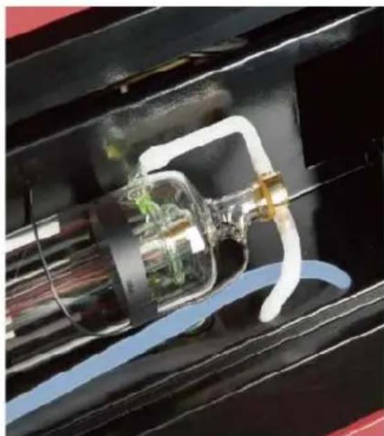
You'll need to place a piece of tape at each stage of the laser path to confirm that the platform remains properly aligned. If not, you will be unable to correct the problem. Once the supplied tapes run out, we recommend using masking tapes as it is easy to manage and use.
If beam alignment is performed carelessly, the operator may be exposed to a small amount of radiation. Follow these procedures correctly and also be careful when performing beam alignment.
Perform beam alignment at low power levels: 15% or less. Any higher percentage will cause the laser to ignite the test strip instead of marking. Make sure to set the maximum power (not the minimum) to 15%.
LASER TUBE ALIGNMENT.
To test the alignment of the laser tube with the first mirror, cut a small piece of tape and place it on the frame of the mirror.
Do not place the tape directly on the mirror. Turn on the machine at a power level of 15% or lower.
Press PULSE to manually fire the laser. You should be able to see a mark on the tape. If it doesn't notice, press PULSE again.
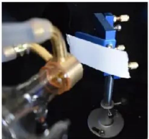
Press the pulse to activate the laser. Always make sure that the path between the laser and its target is unobstructed. Never allow foreign objects to enter between the laser and its target. When pressing the
PULSE button, be careful not to leave any part of your body in the path.
The laser mark should be close to the center of the hole. If the laser is centered on the first mirror, cut off the power of the laser and carefully adjust the laser tube in its holder. This may require loosening the bolts on its bracket. Be careful not to over-loosen the bolts and not over-tighten the bolts. Only one stand can be adjusted at a time.
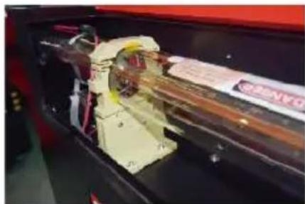
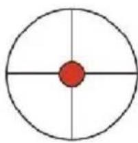
These marks are OK.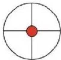
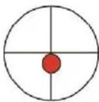
These marks require adjustment.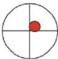
FIRST MIRROR ALIGNMENT.
After ensuring that the laser light is properly aligned between the laser and the first mirror, check the alignment between the first mirror and second mirror. First, use the directional arrows on the control panel to send the second mirror to the back of the bed along the Y axis.
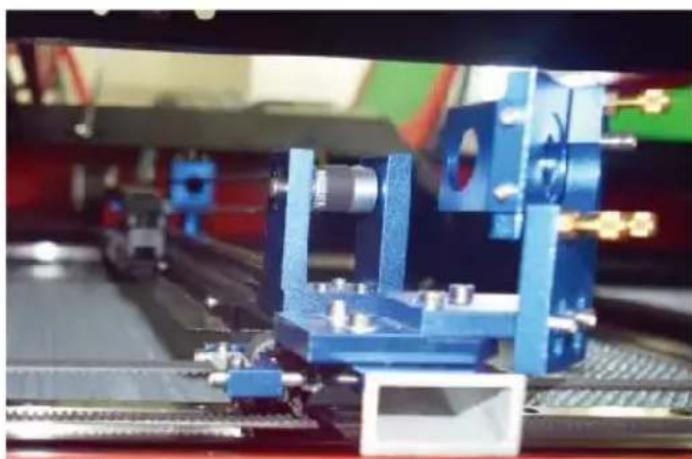
Once set, place a piece of tape on the frame of the second mirror. Do not place tape directly on the mirror. Repeat the previous step. If the laser is centered on the second mirror, the set screws of the first mirror need to be adjusted accordingly.
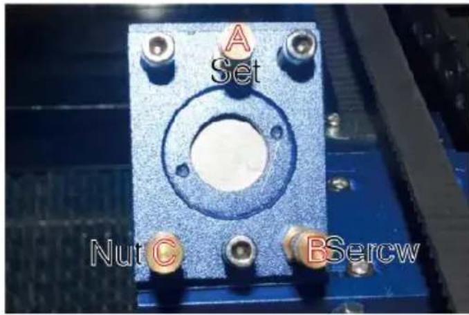
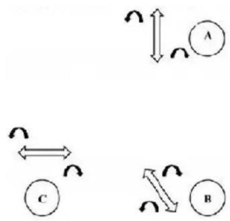
To adjust the mirror, loosen the nut on the screw and gently turn the screw clockwise or counterclockwise. Each screw adjusts a different position or angle. Keep track of the screws you are adjusting and the direction of adjustment. Do not turn the screw more than 1/4 turn at a time, and test the position of the laser after each adjustment so that you can see the effect of each adjustment. Test until the beams are properly aligned, then retighten the nuts on the screws when all adjustments have been made. Next, use the directional arrows on the control panel to send the second mirror to the front of the bed along the Y axis.
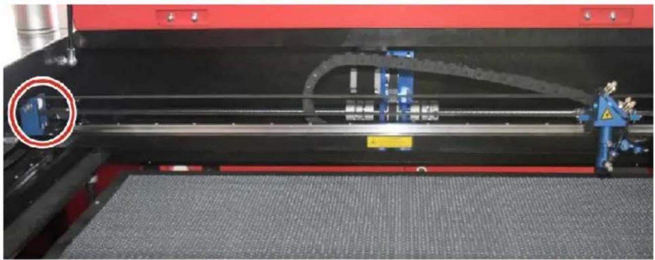
Once set, place another strip of tape on the frame of the second mirror. Do not place the tape directly on the mirror. Repeat the steps in 5.4.1 if necessary, adjust the set screws on the first mirror. Test again until the beams are properly aligned, then retighten the nuts on the screws.
SECOND MIRROR ALIGNMENT.
The laser mark should be close to the center of the hole. If the laser is centered on the first mirror, cut off the power of the laser and carefully adjust the laser tube in its holder. This may require loosening the bolts on its bracket. Be careful not to over-loosen the bolts and not over-tighten the bolts. Only one stand can be adjusted at a time.
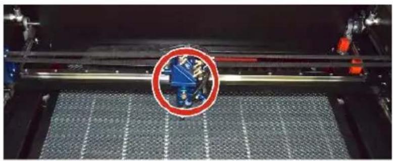
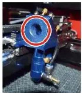
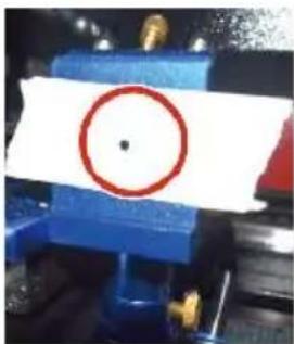
THIRD MIRROR ALIGNMENT.
After ensuring that the laser is properly aligned between the 2nd and 3rd mirrors, check the alignment between the 3rd mirror and the table. Remove the air assist hose from the laser head. Then, place a piece of paper on the bottom of the laser head and press it firmly against the nozzle; it will leave a ring mark that can help you check the accuracy. Repeat steps in 5.4.1. If the laser is not centered through the laser head, adjust the set screw of the third mirror accordingly as shown in 5.4.2. Test again until the beams are properly aligned, then retighten the nuts on the screw.
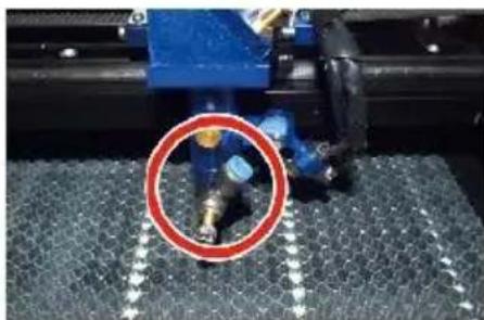
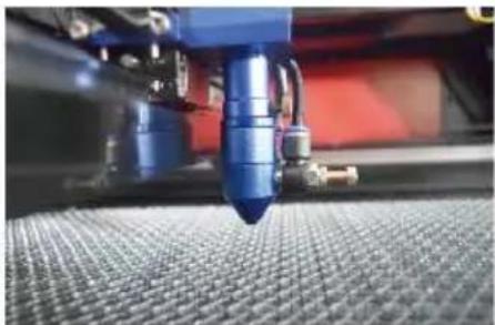
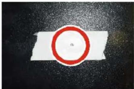
- INSTALL THE LASER TUBE.
Schematic diagram of laser tube installation:
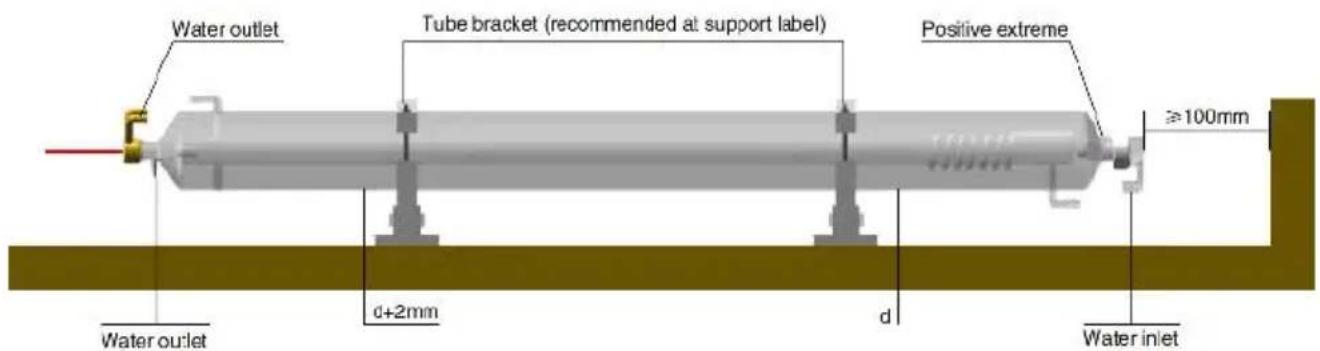
- Please install it according to the logo on the laser, and correctly connect the cathode and anode connection wires, water inlet pipe and water outlet pipe of the laser.
- Turn on the chiller and adjust the laser angle to ensure that the water flows through the full length of the laser and there is no clogging.
- Remove the optical aperture mark, and then turn on the laser power supply for optical path debugging. PROBLEMS AND TROUBLESHOOTING.
Problem 1: The laser is always output at maximum power, or the power is not adjustable.
①The laser is equipped with a power control terminal that is incorrectly connected; Please check the terminal connection carefully. ②The laser is equipped with a power failure; Please try replacing the power supply. ③Failure of the control board of the laser machine; Please contact customer service.
Problem 2: The laser does not emit light.
①The laser is equipped with a power control terminal that is incorrectly connected, or the control connection line is broken; Please check carefully whether the terminals and connecting wires are misconnected or do not turn on. ②The chiller water protection fails, and the chiller coolant is insufficient. Replace the water protector or add coolant. ③Lasers are equipped with power failures, or power supply problem. Try replacing the power cord with a power supply, or a mains power
cord.
④ Failure of the control board of the laser machine; Please contact customer service. ⑤ Laser failure; Please contact customer service.
Problem 3: Discharge ignition.
① The connection line between the laser and the laser equipped power supply is damaged or broken; Try replacing the cable. ② Laser failure; Please contact customer service.
Problem 4: Requirements for the environment.
The laser is equipped with a power supply and needs to operate in a well-ventilated environment. The workspace needs to meet local safety standards for the operation of laser equipment.
Note: Environmental Requirements.
Operating temperature: 10°C to 38°C
Storage temperature: -10°C to 35°C. Storage humidity:
20%RH to 80%RH
5. LUBRICATION INSTRUCTIONS.
For best results, clean and lubricate the rails of the engraving machine every two weeks.
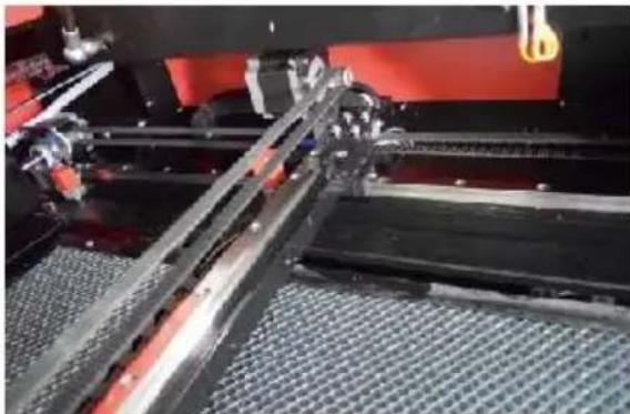
- Turn off the laser engraving machine. Gently move the laser head out of the way.
- Wipe all dust and debris off the X- and Y-axis rails with a dry cotton cloth until they are shiny and clean.
- Do the same for the Z-axis screws.
- Lubricate the rails and screws with grease. Gently move the laser head and X-axis so that the lubricant is evenly distributed along the two rails, and raise and lower the bed to evenly distribute the lubricant along the screws.
DAILY TROUBLESHOOTING TABLE
| ISSUE | CAUSE OF THE PROBLEM | SOLUTION |
| The panel indicates that he machine is protected | The door is not dosed | Close the door |
| The cover protection switch is damaged | Replace with a new one |
| The panel indicates that the machine has a defe in water ingress protectie | The water pipes are clogged ar there a no water circulation | Clean the water pipe |
| The pump doesn't come out,the pump breaks | Replace with a new one |
| Impaired water resistance | Replace with a new one |
| The panel prompts the working hyper inter face | The cutting paper size is too la | Resize the image |
| The machine anchor point is incorrect | Retargeting |
| Laser cutting is impermeable | The light path of the laser is r correct | Adjust the optical pat |
| Mirrors and lenses are dirty | Wash with alcohol |
| Does not emit lasers | Problems with laser tubes | Replace with a new one |
| Lager power issues | Replace with a new one |
| The Y-axis does not Move | The rotary switch is not turned | Tum off the rotary switch |
| Poor relay connection | Reposition the relay replace it with a new one |
| The scan panel indicate that the buffer distance is insufficient | The X-axis laser head is too far away from one aide | Reposition the X-axis laser head so that it is 50 mm away from the origin |
| The reset switch on the machine is not turned off function | The limit switch is damaged or limit line is damaged, and the sw in the e-chain@is disconnected | Replace with a new red limit switch |
ACCESSORIES LIST
- Instructions *1
- Smoke exhaust pipes *1
- Double-sided tape *1
- Clamps *1
- Screwdriver *1
- Allen key *1 SET
- Grounding wire *1
- Power cord *1
- Data cable *1
- Crystal network cable *1
- Document bag *1
- Flash drive *1
Address: Shuangchenglu 803nong11hao1602A-1609shi, Baoshanqu, Shanghai 200000 CN.
Imported to AUS: SIHAO PTY LTD, 1 ROKEVA STREET EASTWOOD NSW 2122 Australia
Imported to USA: Sanven Technology Ltd., Suite 250, 9166 Anaheim Pla Rancho Cucamonga, CA 91730

E-CrossStu GmbH
Mainzer Landstr.69, 60329 Frankfurt am Main

YH CONSULTING LIMITED.
C/O YH Consulting Limited Office 147, Centurion H, London Road, Staines-upon-Thames, Surrey, TW18 4
VEVOR
TOUGH TOOLS, HALF PRICE
Technical Support and E-Warranty Certificate www.vevor.com/support
VEVOR
INSTRUCTION MANUAL
MODEL: KH5030/KH6040/KH7050/KH906/KH1490
KH-5030/KH-6040/KH-7050/KH-906/KH-1490
We continue to be committed to provide you tools with competitive price. "Save Half", "Half Price" or any other similar expressions used by us only represent the estimate of savings you might benefit from buying certain tools with us compared to top brands and does not necessarily mean to cover all categories of tools offered. We are kindly reminded to verify carefully when you are placing an order with us actually saving half in comparison with the top major brands.
MODEL: KH5030/KH6040/KH7050/KH9060/KH1490
KH-5030/KH-6040/KH-7050/KH-906/KH-1490
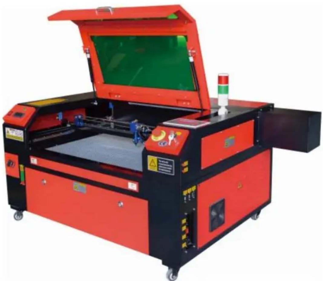
Have product questions? Need technical support? Please feel free to contact us:
Technical Support and E-Warranty Certificate www.vevor.com/support
This is the original instruction. Please read all manual instructions carefully before operating. VEVOR reserves a clear interpretation of the user manual. The appearance of the product shall be subject to the product you received. Please forgive us that we won't inform you of any technology or software updates on our product.
MAIN COMPONENTS AND DESCRIPTIONS
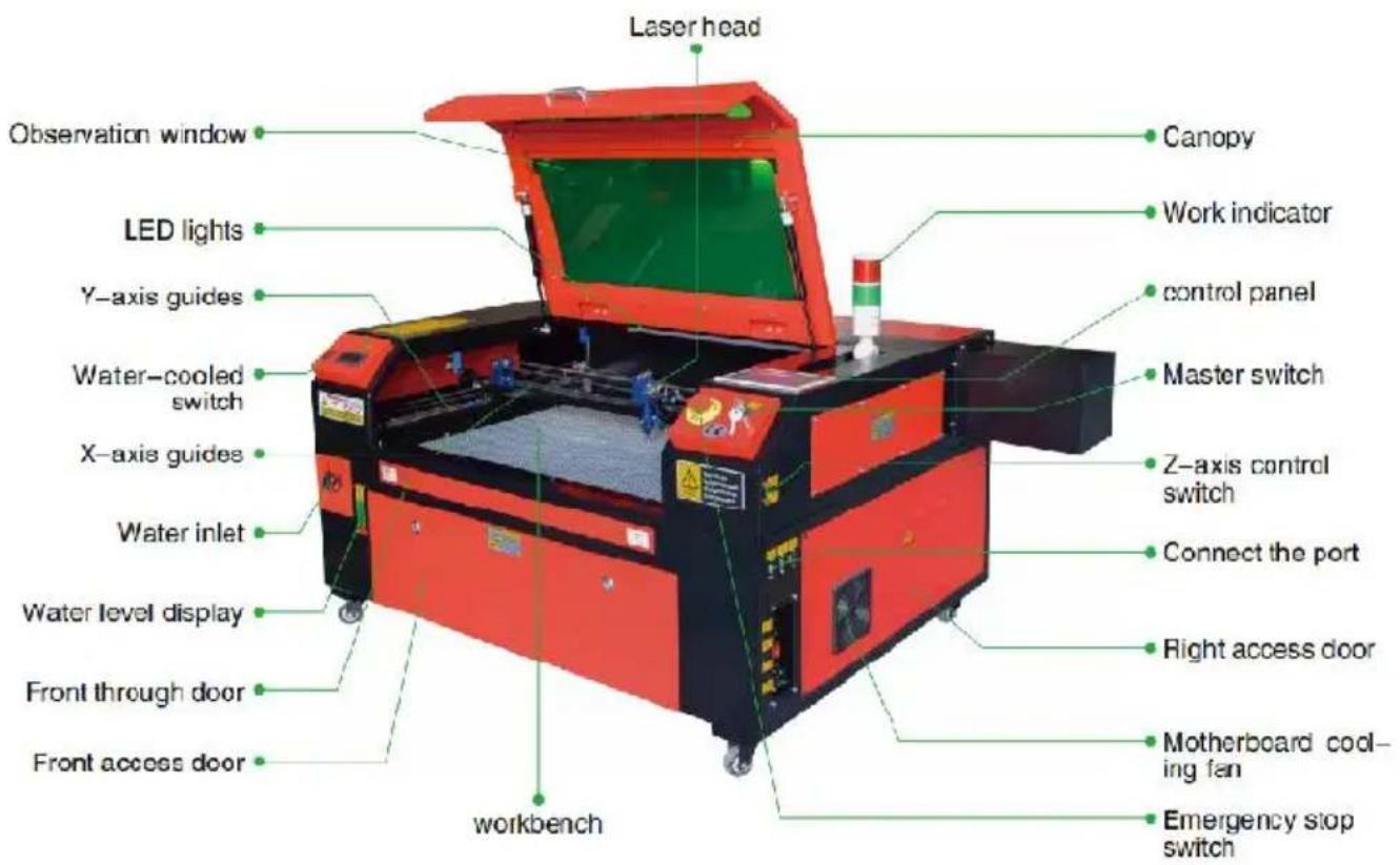
- Schematic diagram of the pierce.
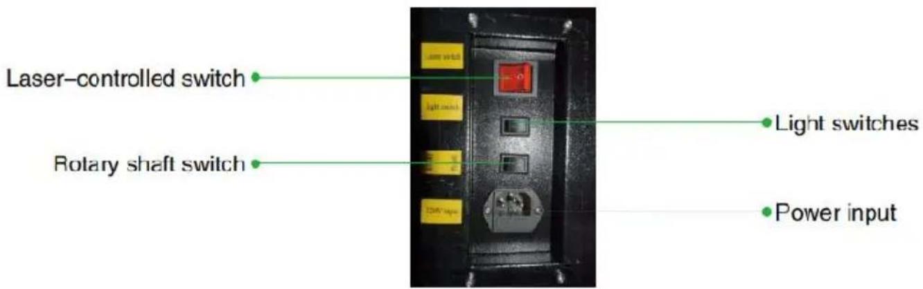
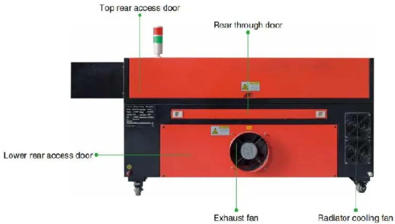
2. Description of the part.
Point Shot Button: The laser tube is pointed at the light

OK key: Used for user confirmation

Autofocus key: Automatically finds the locus point

Speed key: Sets the current machining speed value


Z-axis key: Used to move the Z-axis


U-axis key: Used to move the U-axis

StartPause key: Start work or pause/restart work

Decimal Point: Used to set parameters with decimals

Power button: Set the current maximum and minimum power values

Jog/Continuous Key: Jog motion and continuous motion switching

Toggle keys: Combine with number keys to form key combinations, or toggle special functions.

Exit key: Used to return to the previous menu, cancel parameter settings, etc.

Menu keys: user parameters, manufacturer parameters, language settings, etc.

Border Key: Performs a boundary traversal operation on the tile being processed.

File Keys: Memory file and USB flash drive file management.

D-pad: Used to move options when setting parameters in the menu.
Numeric keys 0-9: used to set parameters; the keys with characters in the upper right corner can be combined with the toggle keys.
These marks require adjustment.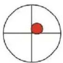
FIRST ALIGNMENT OF THE MIRROR.
Contact customer service.
DAILY TROUBLESHOOTING TABLE
C/O YH Consulting Limited Office 147, Centurion H, London Road, Staines-upon-Thames, Surrey, TW18 4
VEVOR
TOUGH TOOLS, HALF PRICE
We continue to be committed to provide you tools with competitive price. "Save Half", "Half Price" or any other similar expressions used by us only represent the estimate of savings you might benefit from buying certain tools with us compared to top brands and does not necessarily mean to cover all categories of tools offered. We are kindly reminded to verify carefully when you are placing an order with us actually saving half in comparison with the top major brands.
MODEL: KH5030/KH6040/KH7050/KH9060/KH1490
KH-5030/KH-6040/KH-7050/KH-906/KH-1490
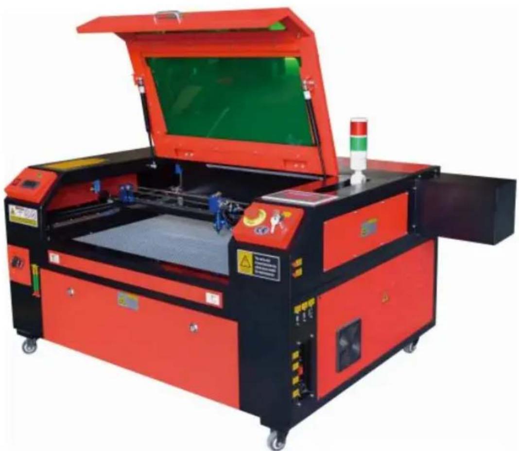
Have product questions? Need technical support? Please feel free to contact us:
Technical Support and E-Warranty Certificate www.vevor.com/support
This is the original instruction. Please read all manual instructions carefully before operating. VEVOR reserves the right to interpret the user manual. The appearance of the product shall be subject to the product you received. Please forgive us that we won't inform you if there are any technology or software updates on our product.
MAIN COMPONENTS AND DESCRIPTIONS
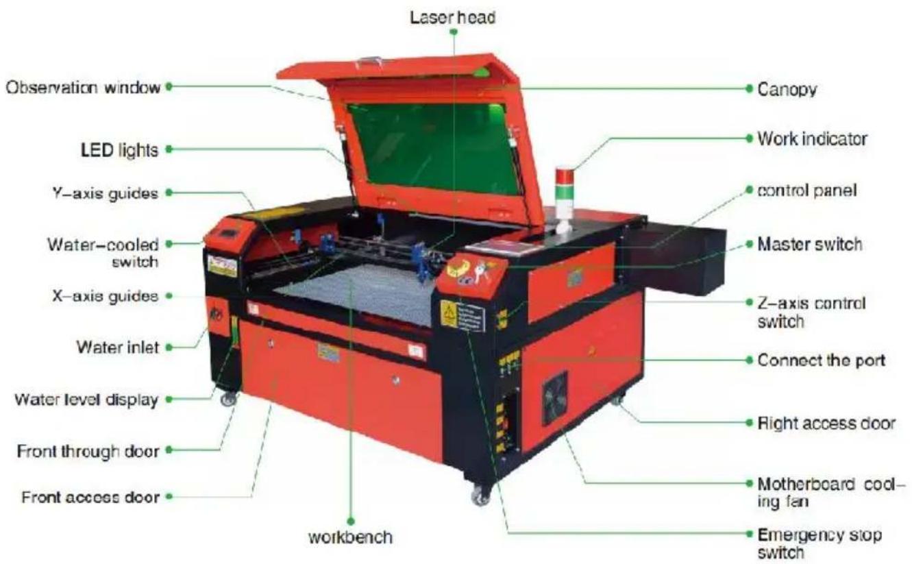
Point Shot Button: The laser tube is pointed at the light

OK key: Used for user confirmation

Autofocus key: Automatically finds the locus point

Start/Pause key: Start work or pause/restart work

Decimal Point: Used to set parameters with decimals

Power button: Set the current maximum and minimum power values

Jog/Continuous Key: Jog motion and continuous motion switching

Toggle keys: Combine with number keys to form key combinations, or toggle special functions

Exit key: Used to return to the previous menu, cancel parameter settings, etc.

Menu keys: user parameters, manufacturer parameters, language settings, etc.

Speed key: Sets the current machining speed value.

Border Key: Performs a boundary traversal operation on the file being processed.


Z-axis key: Used to move the Z-axis.

File Keys: Memory file and USB flash drive file management.


U-axis key: Used to move the U-axis.

D-pad: Used to move options when setting parameters in the menu.
Numeric keys 0-9: used to set parameters; the keys with characters in the upper right corner can be combined with the toggle keys.
Permission not activated!

Change permission code.
These marks require adjustment.
DAILY TROUBLESHOOTING TABLE
TOUGH TOOLS, HALF PRICE
We continue to be committed to providing you tools with competitive prices. "Save Half", "Half Price" or any other similar expressions used by us only represent the estimate of savings you might benefit from buying certain tools with us compared to top brands and does not necessarily mean to cover all categories of tools offered. We kindly remind you to verify carefully when placing an order with us that you are actually saving half in comparison with the top major brands.
MODEL: KH5030/KH6040/KH7050/KH9060/KH1490 KH-5030/KH-6040/KH-7050/KH-906/KH-1490
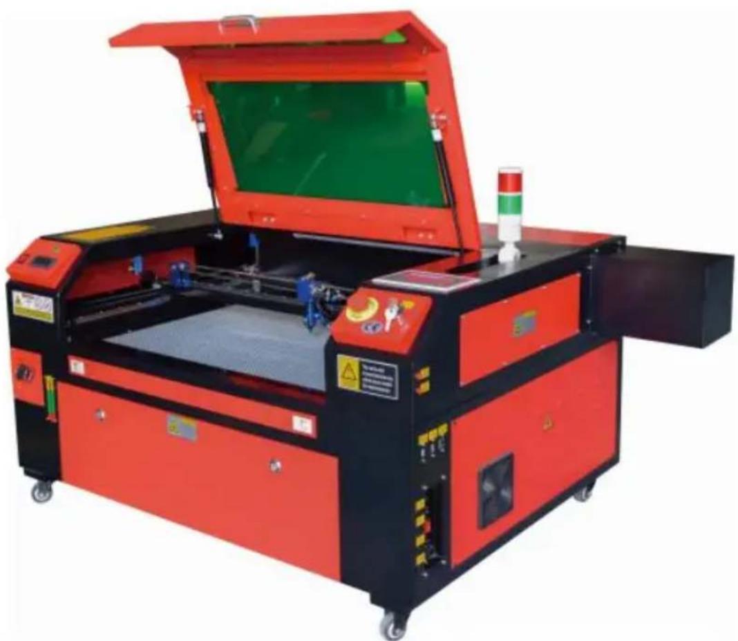
Have product questions? Need technical support? Please feel free to contact us:
Technical Support and E-Warranty Certificate www.vevor.com/support
This is the original instruction. Please read all manual instructions carefully before operating. VEVOR reserves a clear interpretation of the user manual. The appearance of the product shall be subject to the product you received. Please forgive us that we won't inform you of any technology or software updates on our product.
Point Shot Button: The laser tube is pointed at the light

OK key: Used for user confirmation

Autofocus key: Automatically finds the locus point

Speed key: Sets the current machining speed value


Z-axis key: Used to move the Z-axis


U-axis key: Used to move the U-axis

Start/Pause key: Start work or pause/restart work

Decimal Point: Used to set parameters with decimals

Power button: Set the current maximum and minimum power values

Jog/Continuous Key: Jog motion and continuous motion switching

Toggle keys: Combine with number keys to form key combinations, or toggle special functions

Exit key: Used to return to the previous menu cancel parameter settings, etc

Menu keys: user parameters, manufacturer parameters, language settings, etc

Border Key: Performs a boundary traversal operation on the tile being processed

File Keys: Memory file and USB flash drive file management

D-pad: Used to move options when setting parameters in the menu
Numeric keys 0-9: used to set parameters, the keys with characters in the upper right corner can be combined with the toggle keys
Permission not activated!


These marks require adjustment
DAILY TROUBLESHOOTING TABLE
Imported in AUS: SIHAO PTY LTD, 1 ROKEVA STREETEASTWOOD NS 2122 Australia
Imported in USA: Sanven Technology Ltd., Suite 250, 9166 Anaheim Place, Rancho Cucamonga, CA 91730
E-CrossStu GmbH
Mainzer Landstr. 69, 60329 Frankfurt am Main
YH CONSULTING LIMITED.
C/O YH Consulting Limited, Office 147, Centurion House, London Road, Staines-upon-Thames, Surrey, TW18 4AX
VEVOR
TOUGH TOOLS, HALF PRICE
We continue to be committed to providing you tools with competitive prices. "Save Half", "Half Price" or any other similar expressions used by us only represent the estimate of savings you might benefit from buying certain tools with us compared to top brands and does not necessarily mean to cover all categories of tools offered. We kindly remind you to verify carefully when placing an order with us that you are actually saving half in comparison with the top major brands.
MODEL: KH5030/KH6040/KH7050/KH9060/KH1490
KH-5030/KH-6040/KH-7050/KH-906/KH-1490
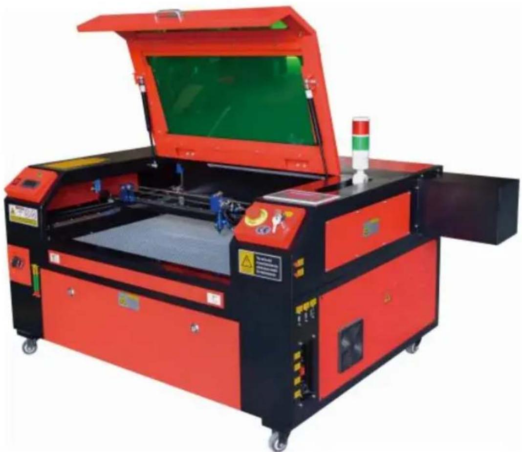
Have product questions? Need technical support? Please feel free to contact us:
Technical Support and E-Warranty Certificate www.vevor.com/support
This is the original instruction. Please read all manual instructions carefully before operating. VEVOR reserves the right to interpret the user manual. The appearance of the product shall be subject to the product you received. Please forgive us that we won't inform you of any technology or software updates on our product.
Point Shot Button: The laser tube is pointed at the light

OK key: Used for user confirmation

Autofocus key: Automatically finds the focal point

Start/Pause key: Start work or pause/restart work

Decimal Point: Used to set parameters with decimals

Power button: Set the current maximum and minimum power values

Jog/Continuous key: Jog motion and continuous motion switching

Toggle keys: Combine with number keys to form key combinations, or toggle special functions

Exit key: Used to return to the previous menu, cancel parameter settings, etc.

Menu keys: user parameters, manufacturer parameters, language settings, etc.

Speed key: Sets the current machining speed value

Border Key: Performs a boundary traversal operation on the file being processed


Z-axis key: Used to move the Z-axis

File Keys: Memory file and USB flash drive file management


U-axis key: Used to move the U-axis

D-pad: Used to move options when setting parameters in the menu
Numeric keys 0-9: used to set parameters, the keys with characters in the upper right corner can be combined with the toggle keys
Permission not activated!

Change permission code
These marks require adjustment
DAILY TROUBLESHOOTING TABLE
We continue to be committed to providing you tools with competitive prices. "Save Half", "Half Price", or any other similar expressions used by us only represent the estimate of savings you might benefit from buying certain tools with us compared to top brands and does not necessarily mean to cover all categories of tools offered. We kindly remind you to verify carefully when placing an order with us that you are actually saving half in comparison with the top major brands.
MODEL: KH5030/KH6040/KH7050/KH9060/KH1490
KH-5030/KH-6040/KH-7050/KH-906/KH-1490
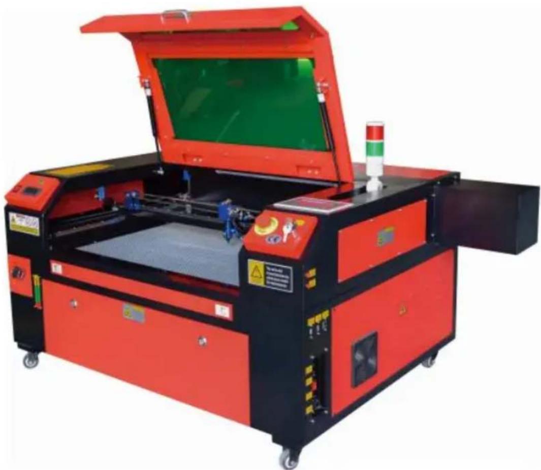
Have product questions? Need technical support? Please feel free to contact us:
Technical Support and E-Warranty Certificate www.vevor.com/support
This is the original instruction. Please read all manual instructions carefully before operating. VEVOR reserves a clear interpretation of the user manual. The appearance of the product shall be subject to the product you received. Please forgive us that we won't inform you of any technology or software updates on our product.
MAIN COMPONENTS AND DESCRIPTIONS
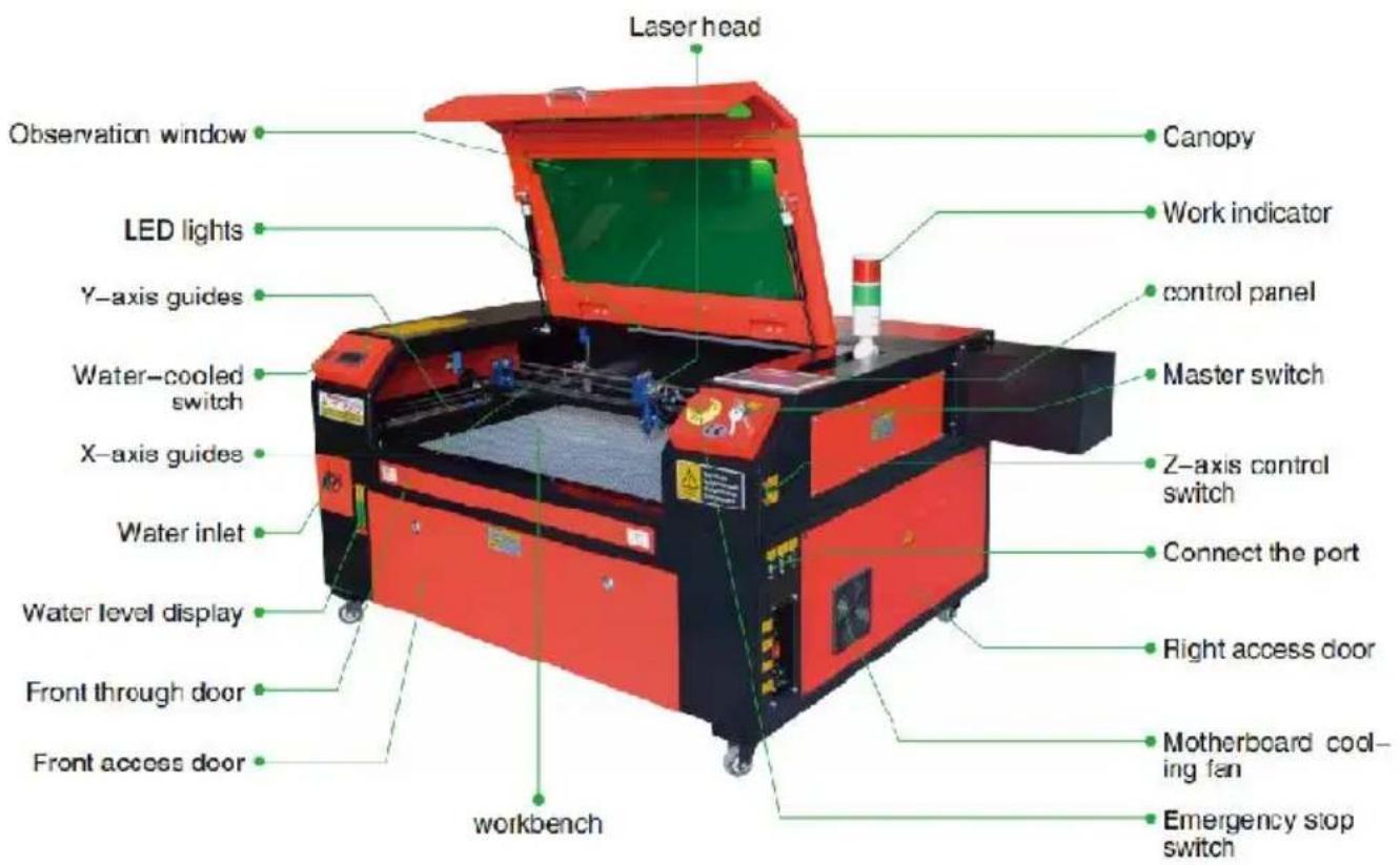
Point Shot Button: The laser tube is pointed at the light

OK key: Used for user confirmation

Autofocus key. Automatically finds the locus point

Start/Pause key: Start work or pause/resume work

Decimal Point: Used to set parameters with decimals

Power button: Set the current maximum and minimum power values

Jog/Continuous Key: Jog motion and continuous motion switching

Toggle keys: Combine with number keys to form key combinations, or toggle special functions

Exit key: Used to return to the previous menu, cancel parameter settings, etc.

Menu keys: user parameters, manufacturer parameters, language settings, etc.

Speed key: Sets the current machining speed value

Border Key: Performs a boundary traversal operation on the file being processed


Z-axis key: Used to move the Z-axis

File Keys: Memory file and USB flash drive file management


U-axis key: Used to move the U-axis

D-pad: Used to move options when setting parameters in the menu
Numeric keys 0-9: used to set parameters, the keys with characters in the upper right corner can be combined with the toggle keys
Show description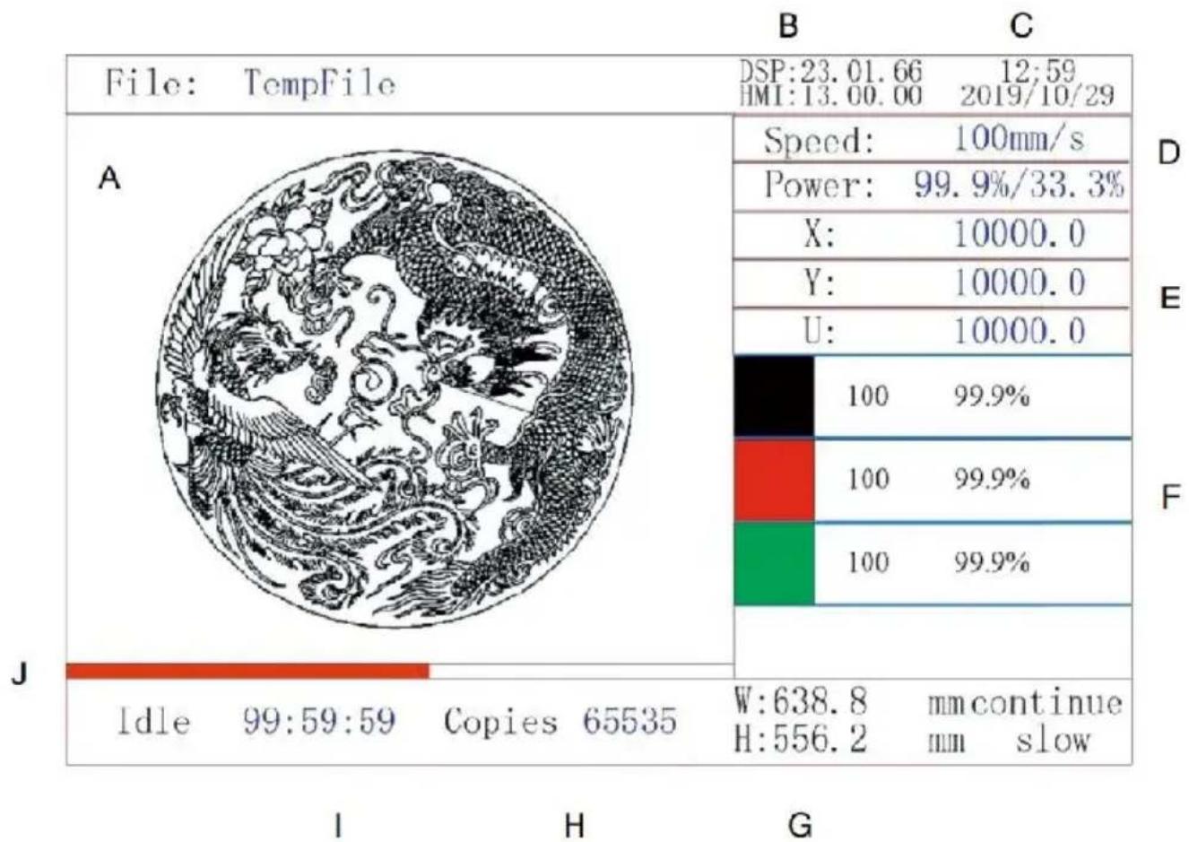
WATER INLET SHUT-OFF.
Permission not activated!

Change permission code
These marks are OK. These marks require adjustment.
FIRST MIRROR SETTING
DAILY TROUBLESHOOTING TABLE
Imported into AUS: SIHAO PTY LTD, 1 ROKEVA STREET EASTWOOD NSW 2122 Australia
Imported into USA: Sanven Technology Ltd., Suite 250, 9166 Anaheim
YH CONSULTING LIMITED. C/O YH Consulting Limited Office 147, Centurion H, London Road, Staines-upon-Thames, Surrey, TW18 2
VEVOR
TOUGH TOOLS, HALF PRICE
We continue to be committed to provide you tools with competitive price. "Save Half", "Half Price" or any other similar expressions used by us only represent the estimate of savings you might benefit from buying certain tools with us compared to top brands and does not necessarily mean to cover all categories of tools offered. Are kindly reminded to verify carefully when you are placing an order with us actually saving half in comparison with the top major brands.
MODEL: KH5030/KH6040/KH7050/KH9060/KH1490
KH-5030/KH-6040/KH-7050/KH-906/KH-1490
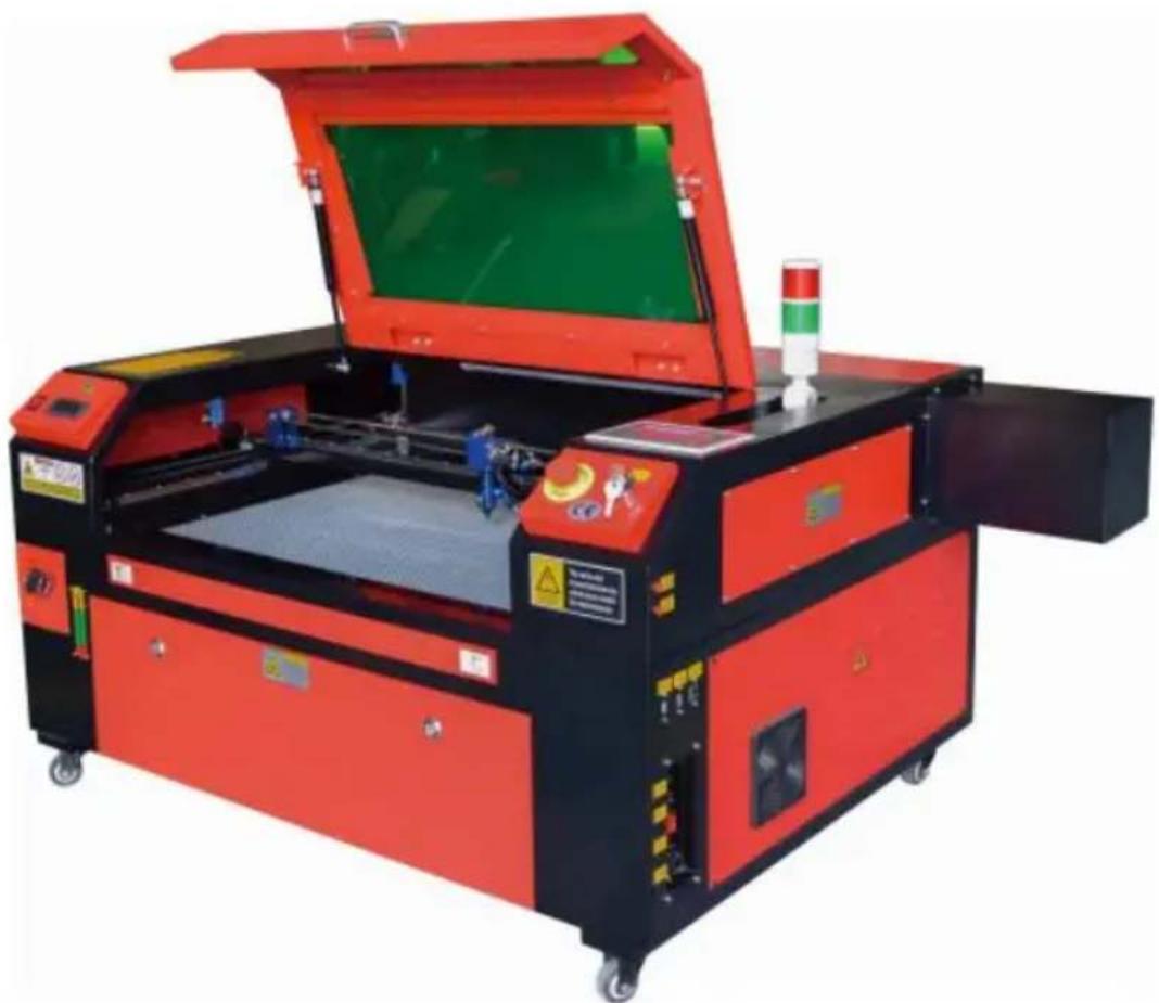
Have product questions? Need technical support? Please feel free to contact us:
Technical Support and E-Warranty Certificate www.vevor.com/support
This is the original instruction. Please read all manual instructions carefully before operating. VEVOR reserves a clear interpretation of the user manual. The appearance of the product shall be subject to the product you received. Please forgive us that we won't inform you of any technology or software updates on our product.
MAIN COMPONENTS AND DESCRIPTIONS
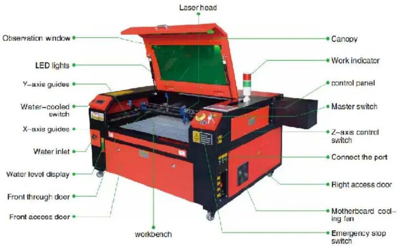
Point Shot Button: The laser tube is pointed at the light

OK key: Used for user confirmation

Autofocus key: Automatically finds the locus point

Speed key: Sets the current machining speed value


Z-axis key: Used to move the Z-axis


U-axis key: Used to move the U-axis

Start/Pause key: Start work or pause/restart work

Decimal Point: Used to set parameters with decimals

Power button: Set the current maximum and minimum power values

Jog/Continuous Key: switches between jog motion and continuous motion.

Toggle keys: combine with number keys to form key combinations, or toggle special functions.

Exit key: used to return to the previous menu, cancel parameter settings, etc.

Menu keys: user parameters, manufacturer parameters, language settings, etc.

Border Key: performs a boundary traversal operation on the tile being processed.

File Keys: memory file and USB flash drive file management.

D-pad: used to move options when setting parameters in the menu.
Numeric keys 0-9: used to set parameters; keys with characters in the upper right corner can be combined with the toggle keys.
6. WATER-COOLED INSTALLATION.
These marks are OK. These marks require adjustment.
FIRST SEAL ALIGNMENT.
DAILY TROUBLESHOOTING TABLE.
C/O YH Consulting Limited Office 147, Centurion H London Road, Staines-upon-Thames, Surrey, TW18 4
VEVOR
TOUGH TOOLS, HALF PRICE
Technical Support and E-Warranty Certificate www.vevor.com/support
VEVOR
We continue to be committed to provide you tools with competitive price. "Save Half", "Half Price" or any other similar expressions used by us only represent the estimate of savings you might benefit from buying certain tools with us compared to top brands and does not necessarily mean to cover all categories of tools offered. We are kindly reminded to verify carefully when you are placing an order with us actually saving half in comparison with the top major brands.
MODEL: KH5030/KH6040/KH7050/KH9060/KH1490
KH-5030/KH-6040/KH-7050/KH-906/KH-1490

Have product questions? Need technical support? Please feel free to contact us:
Technical Support and E-Warranty Certificate www.vevor.com/support
This is the original instruction, please read all manual instruction carefully before operating. VEVOR reserves a clear interpretation user manual. The appearance of the product shall be subject to product you received. Please forgive us that we won't inform you there are any technology or software updates on our product.
MAIN COMPONENTS AND DESCRIPTIONS
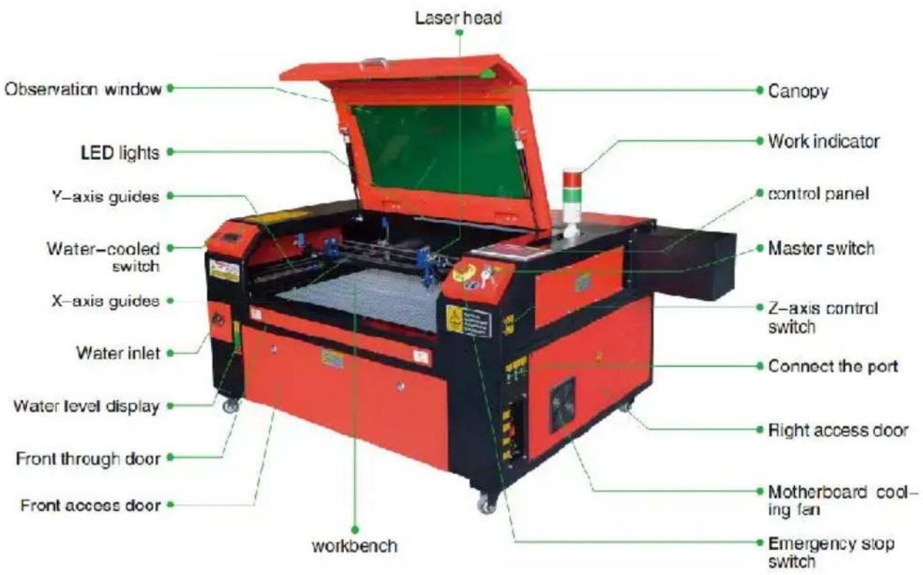
Point Shot Button: The laser tube is pointed at the light

OK key: Used for user confirmation

Autofocus key: Automatically finds the locus point

Speed key: Sets the current machining speed value


Z-axis key: Used to move the Z-axis


U-axis key: Used to move the U-axis

Start/Pause key: Start work or pause/restart work

Decimal Point: Used to set parameters with decimals

Power button: Set the current maximum and minimum power values

Jog/Continuous Key: Jog motion and continuous motion switching

Toggle keys: Combine with number keys to form key combinations, or toggle special functions

Exit key: Used to return to the previous menu, cancel parameter settings, etc.

Menu keys: user parameters, manufacturer parameters, language settings, etc.

Border Key: Performs a boundary traversal operation on the tile being processed

File Keys: Memory file and USB flash drive file management

D-pad: Used to move options when setting parameters in the menu
Numeric keys 0-9: used to set parameters, the keys with characters in the upper right corner can be combined with the toggle keys
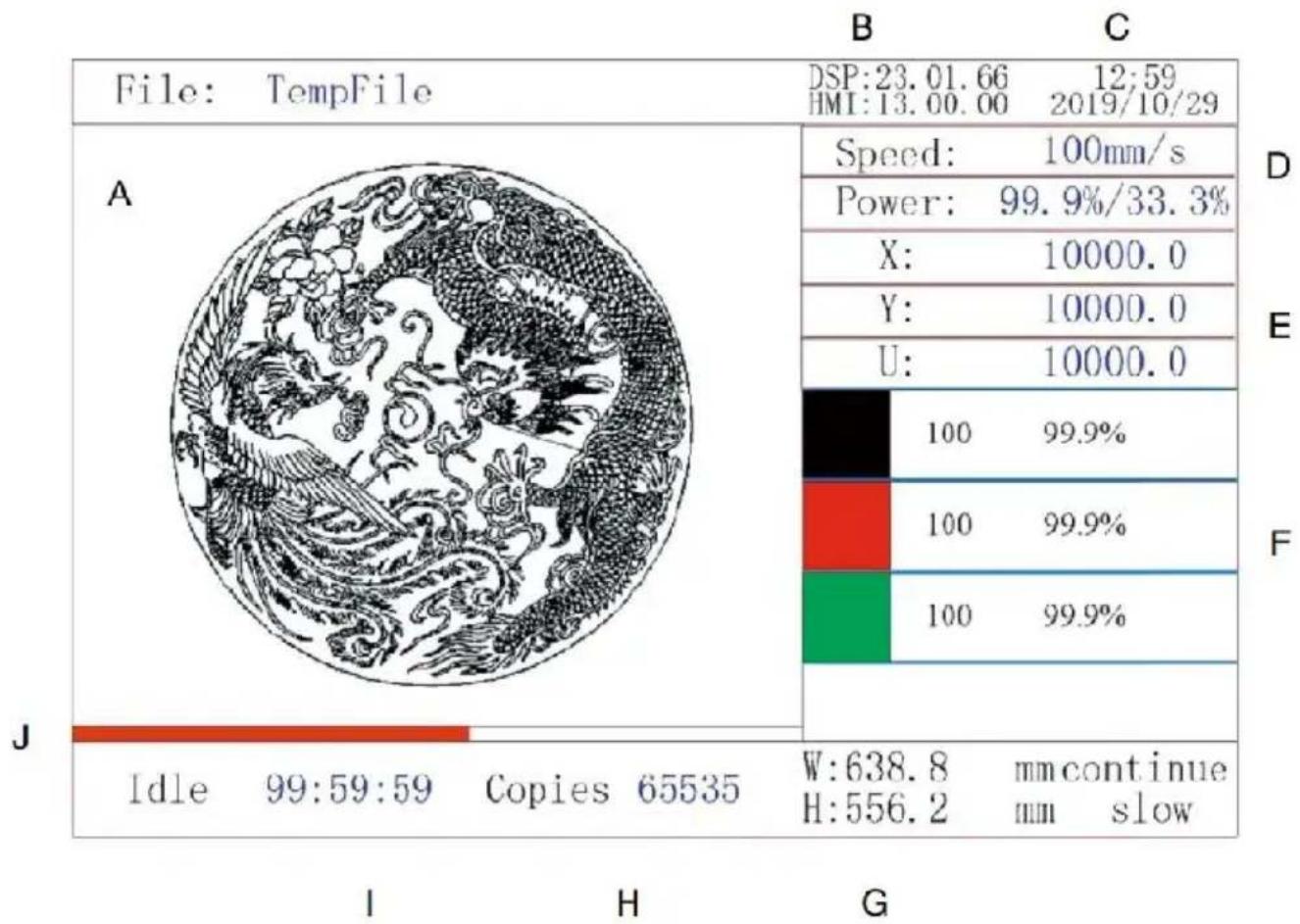
These marks require adjustment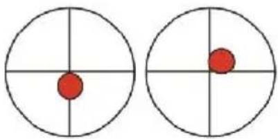
DAILY TROUBLESHOOTING TABLE