JGC30E - Fuel can Vevor - Free user manual and instructions
Find the device manual for free JGC30E Vevor in PDF.

User questions about JGC30E Vevor
0 question about this device. Answer the ones you know or ask your own.
Ask a new question about this device
Download the instructions for your Fuel can in PDF format for free! Find your manual JGC30E - Vevor and take your electronic device back in hand. On this page are published all the documents necessary for the use of your device. JGC30E by Vevor.
USER MANUAL JGC30E Vevor
Technical Support and E-Warranty Certificate www.vevor.com/support
FUEL CADDY USER MANUAL
Model:JGC30E
We continue to be committed to provide you tools with competitive price. "Save Half", "Half Price" or any other similar expressions used by us only represent of savings you might benefit from buying certain tools with us compared to top brands and doses not necessarily mean to cover all categories of tools offered are kindly reminded to verify carefully when you are placing an order with us actually saving half in comparison with the top major brands.
MODEL: JGC-30E
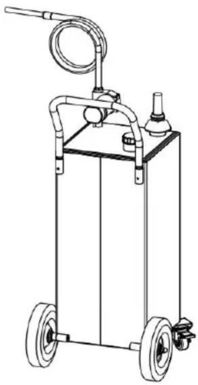
natural_image
Line drawing of a portable water heater with wheels, hose, and control unit (no text or symbols)NEED HELP? CONTACT US!
Have product questions? Need technical support? Please feel fr contact us:

CustomerService@vevor.com
This is the original instruction, please read all manual instruction carefully before operating. VEVOR reserves a clear interpretation user manual. The appearance of the product shall be subject to product you received. Please forgive us that we won't inform you there are any technology or software updates on our product.
WARNING
-
Read carefully and understand all ASSEMBLY AND OPERATION INSTRUCTIONS before operating.
-
Failure to follow the safety rules and other basic safety precautions may result in serious personal injury.
GENERAL SAFETY RULES
When using this product, basic precautions should always be followed, including the following;
- This product is not intended for use by persons (including children) with reduced physical, sensory, or mental capabilities or lack of experience and knowledge unless they have been given supervision or instruction concerning the use of the product by a person responsible for their safety.
- Do not use this product other than intended use.
- Wear proper protective equipment when installing or using this product.
- Ensure all fittings and threaded connections are tightened and leak-free before operating.
A DANGER!
Fuels are extremely flammable. Keep away from heat sparks and ope flames.
- Do not use electronics or mobile communications devices such as mobile phones when pumping flammable liquids.
- Attach ground wire and bond containers being pumped from and in Ground all containers to a known ground source to dissipate static
electricity before pumping liquids.
- Fuel vapors can explode. Harmful or fatal if swallowed. Avoid breathing in fuel vapors.
- Do not smoke near or while using the fuel caddy.
- This product is intended for fuel transfer only and is not designed transport fuel in any vehicle or trailer.
- Do not modify this product.
A WARNING! CAUTION! ATTENTION!
- Do not use this product for prop-longed fuel storage.
- Use the caddy for one fuel type only to avoid possible damage.
● Monitor flow rate and fill level to prevent overflows and spills.
● Always empty the pump and hose after using the caddy. Lift the I and turn the handle onto the opposite direction to empty all rema liquid back into the caddy. - Caution when filling the caddy through the fill tube, monitor closely prevent overflows or spills.
- This product is unsuitable for placing in a yacht, off-road vehicle, a other violent vibration places.

Never use the fuel caddy near open flames or heal sources.
SAVE THESE INSTRUCTIONS
| Model | JGC30E |
| Capacity | 30 Gallons |
| Fuel Type | Diesel,Lubricating Oil, Machine Oil |
| Pump | Input: DC12VPower: 180W |
| Max. Flow | 23.5 L/min |
| Hose | Φ19(Inside Diameter)xL250cm |
| Wheel | 2.5"(Front) ; 10"(Back) |
| Material | Steel |
| Color | Red |
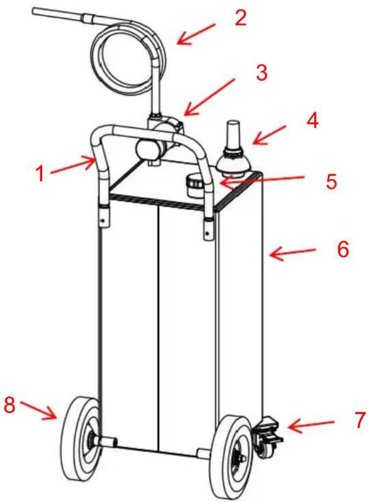
- Handle 2. Hose 3. Pump 4.Oil Dip Rod 5.Fuel Tank Cap
- Fuel Tank 7. Swivel Caster (Front) 8. Fixed Wheel (Back)
COMPONENTS
| No. | Picture | Name and Qty | No. | Picture | Name and Qty |
| 1 |  | Fuel Tank(x1) | 10 |  | Lock Nut(x1) |
| 2 |  | Handle (x1) | 11 |  | Hose Clamp(x1) |
| 3 |  | Fixed Wheel (x2) | 12 |  | Wheel shaft (x2) |
| 4 |  | Hose (x1) | 13 | [ST48] | Oil Gauge Fixing Nut (x1) |
| 5 |  | Swivel Caster (x2) | 14 |  | Oil gauge (x1) |
| 6 |  | Pump (x1) | 15 |  | Hose Fitting(x1) |
| 7 |  | Swivel Caster Film (x2) | 16 |  | Flat Gasket(x2) |
| 8 |  | Raw Tape(x1) | 17 |  | Acorn Nut M12(x2) |
| 9 |  | Grounding Wire (x1) | 18 | / | User Manual(x1) |
ASSEMBLY
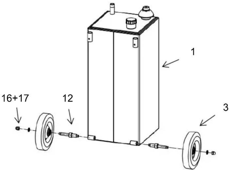
Step 1: Install the fixed wheels. Screw the wheel shafts(12) into the tank, then put the fixed wheels (3)into the wheel shafts and lock the gaskets and nuts.(16+17)
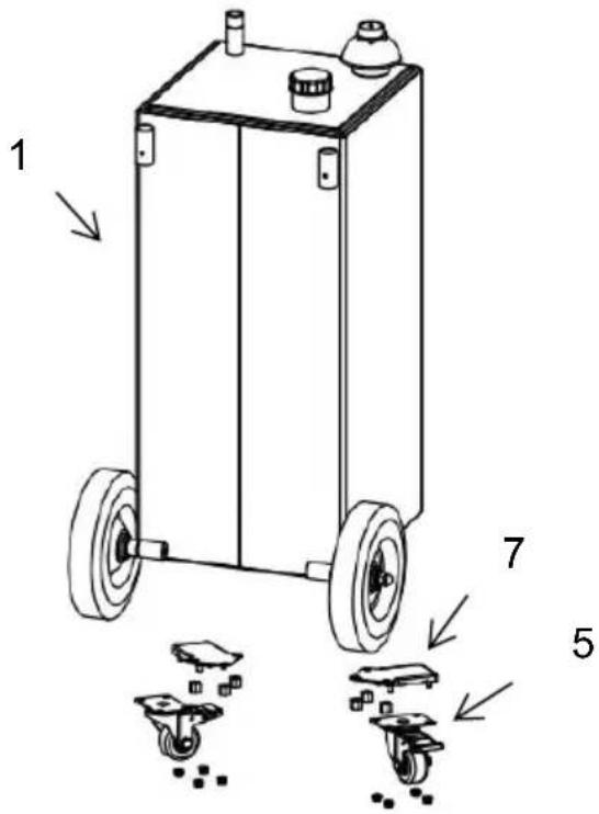
Step 2: Unscrew the nuts first, then install the swivel caster Films(7) the swivel casters(5). Screw the nuts.
Step 3: Screw the lock nut(10) into the oil outlet, Wrap not less than circles of raw material on the outlet, then screw the pump(6) on the and adjust the orientation, and last, lock the pump with the lock nut. Remove the screw on the pump and install the grounding wire(9) on pump with this screw.

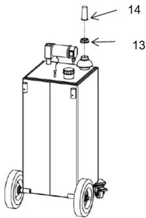
Step 4: Lock the oil gauge(14) on the pump with the oil gauge fixing nut(13), as shown.
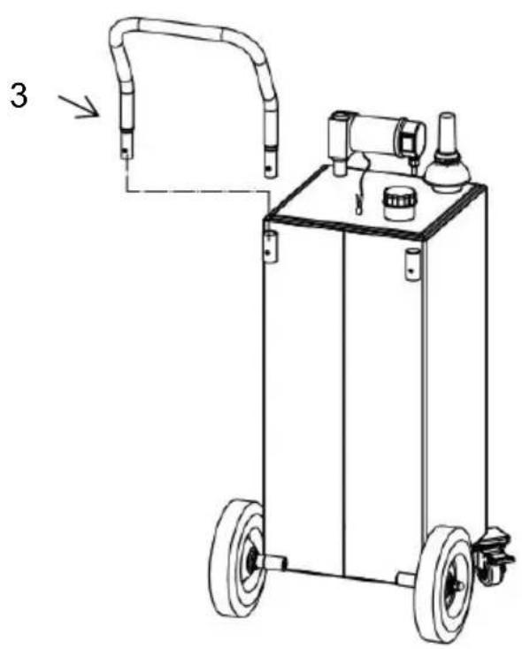
Step 5: Insert the handle(3) into the tank at the appropriate position, shown.
natural_image
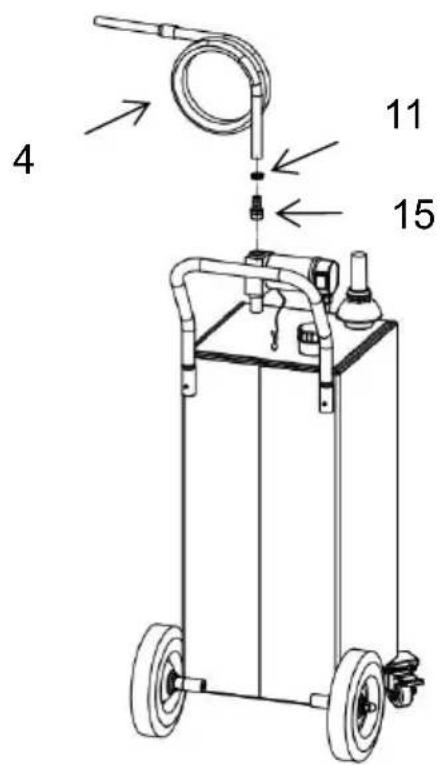
Line drawing of a portable industrial cart with wheels and a handle, no text or symbols presentStep 6: Wrap not less than 5 circles of raw material on the hose f and screw it to the pump outlet. Then attach the hose to the hose and lock it with a hose clamp(11).
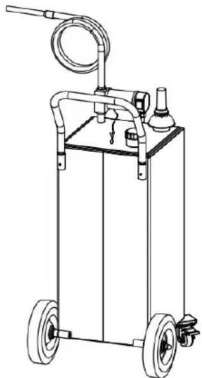
Step 7: The product is assembled and ready for use.
natural_image
Line drawing of a portable industrial cart with wheels, hoses, and a handle (no text or symbols)OPERATION
Refueling operation:
-Please choose the appropriate oil filling, do not fill with water, gasoli other corrosive solvent.
-Do not leave the oil pump empty for more than 1 minute to avoid to the oil pump
-When filling oil, please do a good job of grounding; Connect the clip grounding wire to a good earthing terminal and ensure user safety;
-Open the tank cap, and put the oil into the caddy through the oil in the first time usage, please eliminate air while noticing the measure shows.
-Please do not add the oil beyond the capacity. When the red pointed reaches the highest limit, do not add oil anymore.
-After filling the tank, tighten the cap and keep the tank upright.
Pumping operation:
-Before pumping oil, ground the grounding wire of the fuel tank.
-Ensure that the power supply is 12V DC; Connect the red line of the pump to the positive pole and the black line to the negative pole.
-Turn on the switch of the pump to pump oil.
MAINTENANCE
- Please clean the measure and filter regularly.
- Operate the machine in a horizontal position, do not incline;
- Keep away from fire.
- For different types of oil, it is recommended to clean the tank before storing another type of oil.
- If this product is not used for a long time, it is recommended to store it in a cool and dry environment
Made in China
VEVOR®
TOUGH TOOLS, HALF PRICE
TechnicalSupport and E-Warranty Certificate
www.vevor.com/support
VEVOR®
TOUGH TOOLS, HALF PRICE
natural_image
Line drawing of a portable water cart with wheels, hose, and spray bottle (no text or symbols)BESOIN D'AIDE? CONTACTEZ-NOUS!
natural_image
Line drawing of a portable water cart with attached tubing and control panel (no text or symbols)natural_image
Line drawing of a portable water cart with wheels, hose, and control unit (no text or symbols)OPÉRATION
natural_image
Line drawing of a portable water cart with wheels, hose, and spray bottle (no text or symbols)Kundenservice@vevor.com
natural_image
Line drawing of a portable industrial machine with wheels and a handle, no text or symbols presentnatural_image
Line drawing of a portable water cart with wheels, hose, and spray bottle (no text or symbols)BETRIEB
Tankvorgang:
natural_image
Line drawing of a portable water cart with wheels, hose, and spray bottle (no text or symbols)natural_image
Line drawing of a portable industrial machine with wheels and a handle, no text or symbols presentnatural_image
Line drawing of a portable water cart with wheels, hose, and spray bottle (no text or symbols)OPERAZIONE
CARRITO DE COMBUSTIBLE
MANUAL DEL USUARIO
Modelo: JGC30E
natural_image
Line drawing of a portable water cart with hoses and wheels (no text or symbols)- Mango 2. Manguera 3. Bomba 4. Varilla de medición de aceite 5. Tapa del tanque de combustible 6. Tanque de combustible 7. Rueda giratoria (delantera) 8. Rueda fija (trasera)
COMPONENTES
natural_image
Line drawing of a portable water cart with attached tubing and control panel (no text or symbols)natural_image
Line drawing of a portable industrial cart with wheels, hose, and control unit (no text or symbols)OPERACIÓN
natural_image
Line drawing of a portable water cart with hoses and wheels (no text or symbols)POTRZEBUJESZ POMOCY? SKONTAKTUJ SIĘ Z NAMI!
natural_image
Line drawing of a portable water cart with a handle and control unit, no text or symbols presentnatural_image
Line drawing of a mechanical cart with wheels, hoses, and a handle (no text or symbols)DZIAŁANIE
natural_image
Line drawing of a portable water cart with hoses and wheels (no text or symbols)HULP NODIG? NEEM CONTACT MET ONS OP!
Klantenservice@vevor.com
WAARSCHUWING! LET OP! LET OP!
- Handvat 2. Slang 3. Pomp 4. Oliepeilstok 5. Brandstoftankdop
- Brandstoftank 7. Zwenkwiel (voor) 8. Vast wiel (achter)
COMPONENTEN