
HS-551 - Air horn Vevor - Free user manual and instructions
Find the device manual for free HS-551 Vevor in PDF.
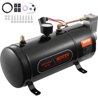


| Product Type | Air Horn for Truck |
| Model | HS-551 |
| Brand | Vevor |
| Supply Voltage | 12 V DC |
| Power | 170 W |
| Working Pressure Range | Start at 90 psi, stop at 120 psi |
| Storage Tank Capacity | 0.8 gal (approx 3 L) |
| Maximum Sound Level | 150 dB |
| Net Weight | 4.5 kg |
| Kit Contents | Compressor, air tube, Teflon tape, 4 rubber pads, safety mounting seat, fuse, M6 bolts (4), M6 nuts (4), M6 washers (4), air hose gasket |
| Main Functions | Compressed air supply for horn, automatic thermal protection, tank drain |
| Maintenance and Cleaning | Regularly drain the tank (every 5 months) to remove condensation; clean the exterior with a dry cloth |
| Safety | Overheat protection; do not touch hot compressor; wear goggles and gloves during assembly; avoid exposure to moisture |
| Spare Parts and Repairability | Replaceable fuse (20A); replaceable solenoid valve; seals and sealing tape available |
| General Information | Complies with EU directive 2012/19/EU (WEEE); do not dispose with household waste |
| Installation | Mount on a flat, cool, dry surface; use the provided M4 bolts and nuts; connect the horn to the compressor with the air tube and Teflon tape |
| Warranty | Refer to the provided warranty certificate |
Frequently Asked Questions - HS-551 Vevor
User questions about HS-551 Vevor
0 question about this device. Answer the ones you know or ask your own.
Ask a new question about this device
Download the instructions for your Air horn in PDF format for free! Find your manual HS-551 - Vevor and take your electronic device back in hand. On this page are published all the documents necessary for the use of your device. HS-551 by Vevor.
USER MANUAL HS-551 Vevor
Technical Support and E-Warranty Certificate www.vevor.com/support
TRUCK AIR HORN
MODEL: HS-660/HS-550/HS-661/HS-551
VEVOR Support Center
HS-660

HS-550

HS-661

HS-551
We continue to be committed to providing you with tools at competitive prices. "Save Half", "Half Price", or any other similar expressions used by us are only an estimate of savings you might benefit from buying certain tools with us compared to the major top brands, and do not necessarily mean to cover all categories offered by us. You are kindly reminded to verify carefully when you are placed with us if you are actually saving half in comparison with the top major brands.
MODEL: HS-660/HS-550/HS-661/HS-551
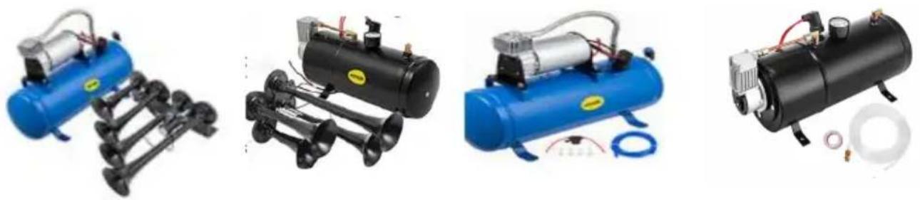
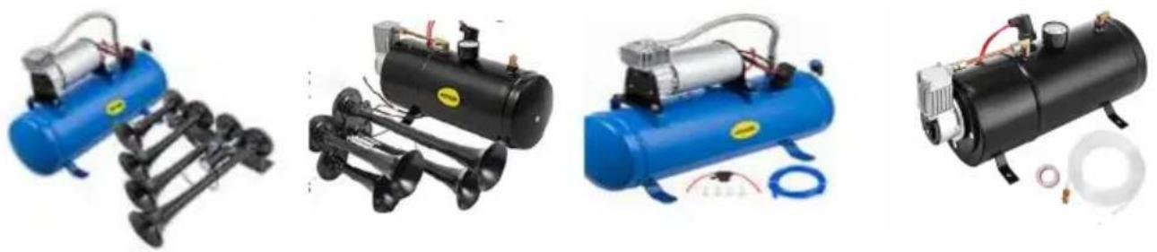
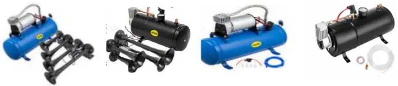
HS-660 HS-550 HS-661 HS-551
NEED HELP? CONTACT US!
Have product questions? Need technical support? Please feel free to contact us:
Technical Support and E-Warranty Certificate www.vevor.com/support
This is the original instruction. Please read all manual instructions carefully before operating. VEVOR reserves a clear interpretation of the user manual. The appearance of the product shall be subject to the product you received. Please forgive us that we won't inform you of any technology or software updates on our product.
PARAMETER LIST
| Model | HS-660 | HS-550 | HS-661 | HS-551 |
| Voltage | 12 | 12 | 12 | 12 |
| Power (w) | 190 | 170 | 190 | 170 |
| Working pressure range (psi) | ON: 90OFF: 120 | ON: 90OFF: 120 | ON: 90OFF: 120 | ON: 90OFF: 120 |
| Storage tank Capacity (gal) | 1.6 | 0.8 | 1.6 | 0.8 |
| Output sound maximum (dB) | 150 | 150 | 150 | 150 |
| Net weight (kg) | 6.1 | 5.45 | 4.65 | 4.5 |
PART LIST
| NO. | Name | HS-660 | HS-550 | HS-661 | HS-551 |
| 1 | compressor | 1 | 1 | 1 | 1 |
| 2 | horn | 2 | 1 | 0 | 0 |
| 3 | Air tube | 1 | 1 | 1 | 1 |
| 4 | Horn connection | 1 | 0 | 0 | 0 |
| 5 | Horn mount | 1 | 1 | 0 | 0 |
| 6 | Teflon tape | 1 | 1 | 1 | 1 |
| 7 | Rubber pad | 4 | 4 | 4 | 4 |
| 8 | Safety mounting seat | 1 | 1 | 1 | 1 |
| 9 | Fuse | 1 | 1 | 1 | 1 |
| 10 | M6 bolt | 12 | 8 | 4 | 4 |
| 11 | M6 nut | 12 | 8 | 4 | 4 |
| 12 | M6 washer | 12 | 4 | 4 | 4 |
| 13 | Air pipe joint | 0 | 0 | 1 | 1 |
SECURITY & WARNINGS
WARNING: Read the instructions before using this product. Failure to do so can result in serious injury. Always observe the rules of safe operation.
- The temperature of the compressor may be very high during operation or after it has stopped, so do not touch it with bare skin.
- Install the system in a level, cool, dry place. Avoid hot and humid environments and do not wet the compressor motor.
- The speaker is very loud, so keep your ears away from the speaker to prevent damage to your ears.
- This product is not a toy. Do not allow children to play with it.
ASSEMBLY PRECAUTIONS:
- Assemble only according to these instructions. Improper assembly can create hazards.
- Wear ANSI-approved safety goggles and heavy-duty work gloves during assembly.
- Keep the assembly area clean and well-lit.
- Keep bystanders out of the area during assembly.
- Do not assemble when tired or when under the influence of alcohol, drugs, or medication.
- Product capabilities apply to properly and completely assembled products only.
- Assemble on a flat, level, hard and smooth surface capable of supporting a fully loaded truck air horn.
SAVE THESE INSTRUCTIONS
OPERATION
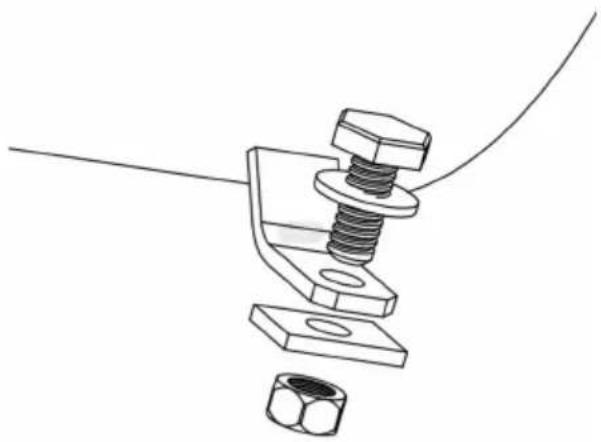
Step 1: Use a 10 mm open wrench or a 10 mm socket wrench to fix the compressor to the car using M6 four nuts, four flat washers, and rubber cushion pads. Install the bolts through the gasket, compressor support, rubber washers, car frame and nuts.
Step 2: Use a 10 mm open wrench or a 10 mm socket wrench to fix the horn support to the horn and the car using four M6 bolts, four M6 nuts, and one tripod. Install the bolts through the tripod - one end through the horn lock nut, and the other through the car lock nut.
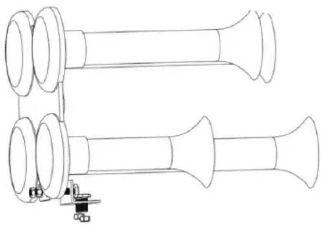
2.1 Model HS-660 Horn Assembly Step 1: Use a 10mm open wrench or a 10mm socket wrench to fix the two horns to the support using four M6 bolts, four M6 nuts, M6 gaskets, and one tripod. Install the bolts through the tripod - through the horn, through the gasket, and lock the nuts.
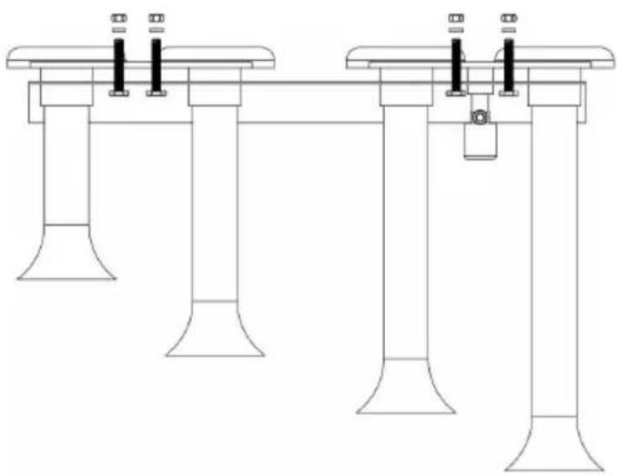
2.2 Model HS-660 Horn Assembly Step 2: Install the connectors of the two horns using the fitting hose butt.
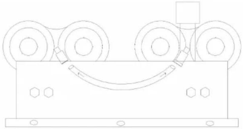
Step 3: Attach the coupling nut to both ends of the hose.
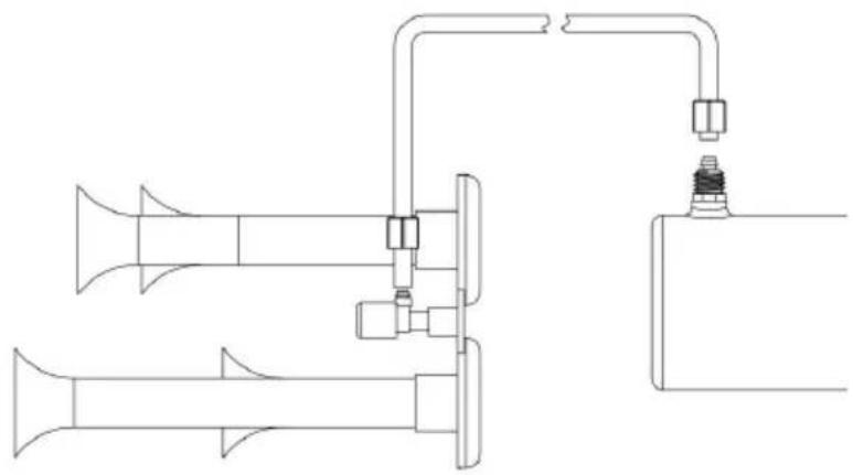
Step 4: Plug the hose into the connector (hose will be easier to install after heating).
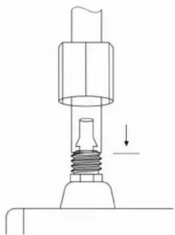
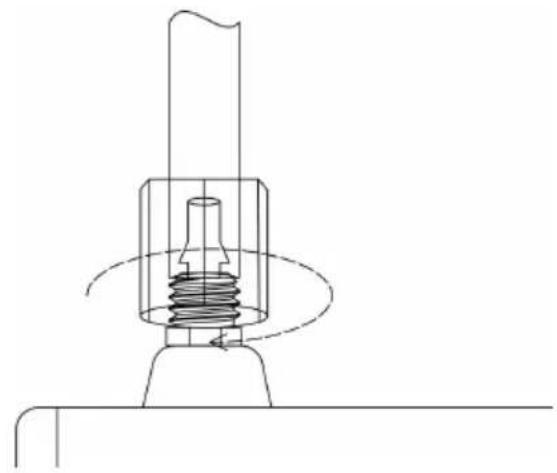
Step 5: Use a 12 mm open-end wrench to tighten the air pipe nut.
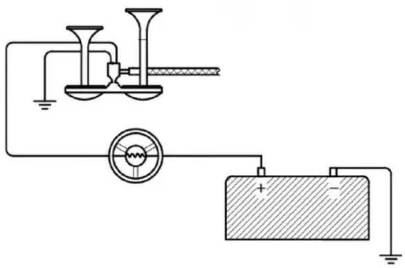
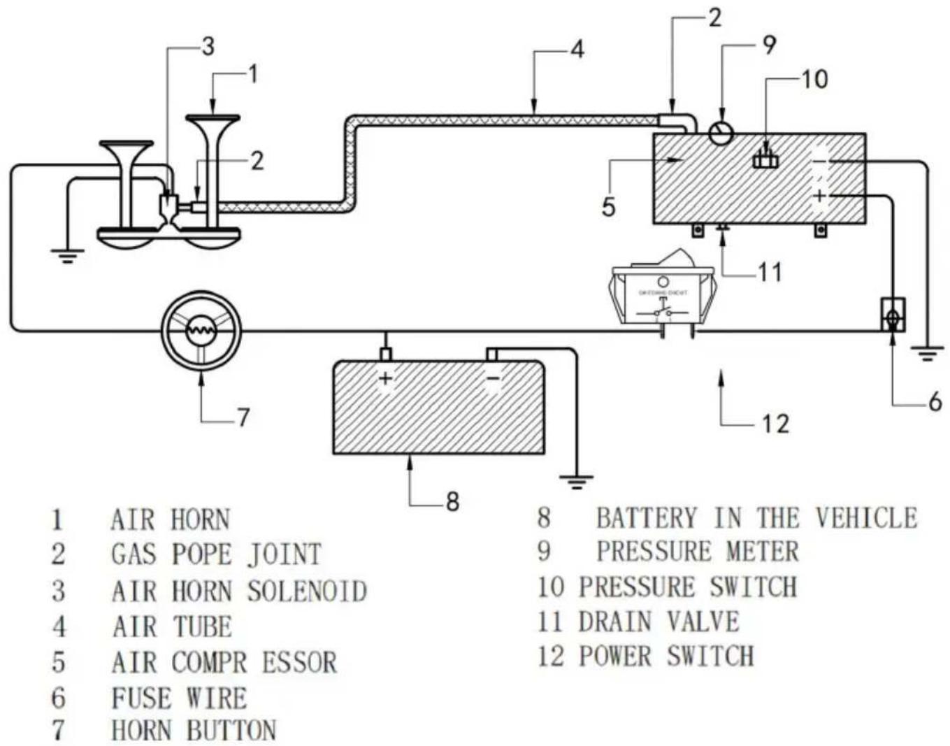
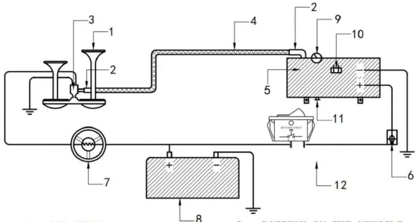
Step 6: Use 16AWG or above copper wire to connect the horn line. The horn has two power lines (regardless of positive or negative terminals), one base iron (negative terminal), and the other is connected to the positive terminal power supply after the horn switch.
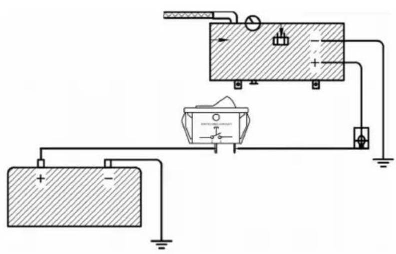
Step 7: Use copper wire 14AWG, 20A power switch, 20A fuse. Connect the compressor line. The black line of the compressor goes to iron (negative electrode), and the red line is connected to the positive electrode of the battery through the power switch.
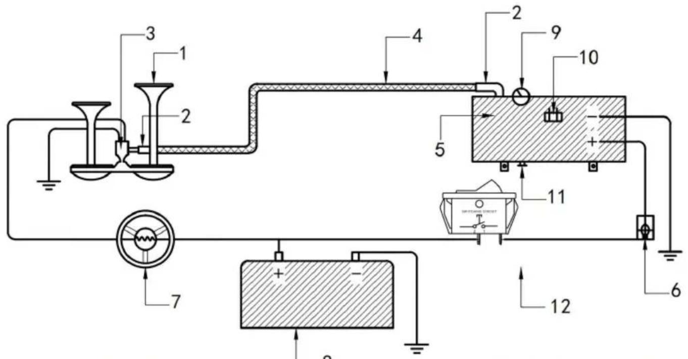
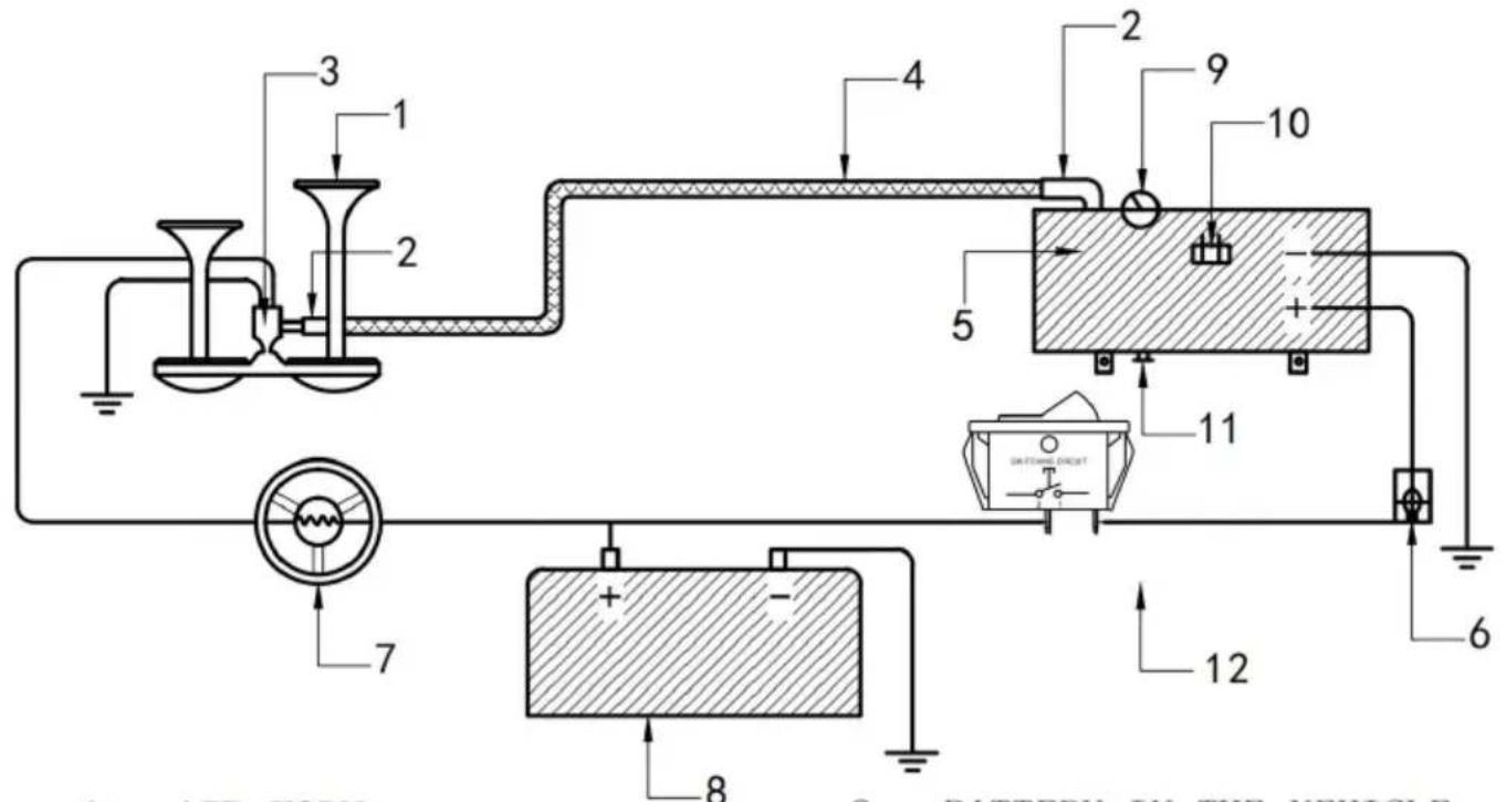
1 AIR HORN 2 GAS PIPE JOINT 3 AIR HORN SOLENOID 4 AIR TUBE 5 AIR COMPRESSOR 6 FUSE WIRE 7 HORN BUTTON
8 BATTERY IN THE VEHICLE 9 PRESSURE METER 10 PRESSURE SWITCH 11 DRAIN VALVE 12 POWER SWITCH
Installation Instructions Added the method of using the drain plug
- Regular inspection (generally every 5 months) should be adjusted according to the use of dry and wet conditions.
The container for discharging condensed gas must have an air pressure less than
Discharge water at 0.1 MPa to avoid danger.
During installation, rotate the sealing tape clockwise and wrap it tightly around the thread. After about 5-10 turns, seal and tighten the drain screw.
Troubleshooting
Automatic Thermal Overload Protection
Your air compressor is equipped with an automatic thermal overload protector. This feature is designed to protect the air compressor from overheating and causing permanent damage. The thermal overload protector will automatically cut power to your air compressor if the internal operating temperature rises above safe levels during excessive use.
If at any time during use your air compressor automatically shuts off, do not attempt to restart it. Turn off the power and allow it to cool for about 20 minutes. This will allow the thermal overload protector to reset so you can safely resume use.
| lank pressure drops when compressors) shut off | 1. Loose drain cock2. Loose connections | 1. Wrap the thread with sealing and tighten it2. Check all connections with soap and water solution and tighten |
| Compressor runs continuously and air flow lower than normal | 1. Excessive air usage2. Loose connections3. Worn piston ring inlet valve. | 1. Decrease air usage2. Check all connections with soap and water solution and tighten. Wrap the leaked joint threads with sealing tape and tighten the Leak joint Thread wrapped with sealing tape and sealed tighten3. Replacement piston or inlet va |
| Excessive moisture in discharge | 1. Excessive water in air tank2. High humidity | 1. Drain tank, tilt tank to drain. I tank more frequently2. Move compressor to area with less humidity, or use air ine filter |
| Compressor will not run | 1. No power, or power switch in OF position2. Blown fuse3. Motor overheats4. Faulty pressure switch (if hooked u to a pressure switch). | 1. Make sure compressor switch ON2. Disconnect compressor from power source, replace fuse. (Refe to Specifications section for conne fuse amperage)3. Let compressor cool off for ab 30 minutes to allow thermal overl switch to reset4. Replace pressure switch |
| Thermal overload protector cuts | 1. Lack of proper ventilation or ambient | 1. Move compressor to well ventilated area, or area with lowe ambient temperature |
| Compressor Abnormal sound excessive knocking or rattling | 1. Loose mounting bolts2. Cylinder or piston ring is worn | 1. Tighten bolts2. Replacement piston or inlet va |
| Horn does no work | 1. The power supply is not powered on2. No compressed a3. Insufficient voltage or current4. Solenoid valve failure | 1. Connect the circuit correctly at turn on the power supply2. Connect the air tube correctly ensure that the air tube is unblo3. Shorten or thicken the horn p cord until the fault disappears, ar connect the horn power cord dire to the automobile battery test4. Replace solenoid valve |

| 1 | air receiver | 9 | Piston connecting rod | 17 | High pressure copper tube | 25 | Horn tracheal joint |
| 2 | Carbon brush plate | 10 | cylinder | 18 | check valve | 26 | solenoid valve |
| 3 | Rotor gasket | 11 | radiator | 19 | Automatic pressure switch | 27 | Horn bracket and screws |
| 4 | rotor | 12 | Cylinder sealing ring | 20 | pressure gauge | 28 | hose |
| 5 | Rotor gasket | 13 | Air sheet | 21 | hose connector | 29 | drain valve |
| 6 | Motor buffer gasket | 14 | Gas seal ring | 22 | Motor power cord | ||
| 7 | motor housing | 15 | The cylinder cover | 23 | Pressure switch dust cover | ||
| 8 | Motor cover plate | 16 | Cylinder head fixing screw | 24 | horn |
CORRECT DISPOSAL
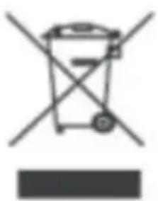
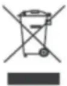
This product is subject to the provisions of European Directive 2012/19/EU. The symbol showing a wheelie bin crossed through indicates that the product requires separate refuse collection in the European Union. This applies to the product and all accessories marked with this symbol. Products marked as such may not be discarded with normal domestic waste and must be taken to a collection point for recycling electrical and electronic devices.
VEVOR®
TOUGH TOOLS, HALF PRICE
VEVOR®
TOUGH TOOLS, HALF PRICE
HS-660

HS-550

HS-661

HS-551
We continue to be committed to provide you tools with competitive price. "Save Half", "Half Price" or any other similar expressions used by us only an estimate of savings you might benefit from buying certain tools with us of the major top brands and does not necessarily mean to cover all categories offered by us. You are kindly reminded to verify carefully when you are placed with us if you are actually saving half in comparison with the top major
MODEL: HS-660/HS-550/HS-661/HS-551
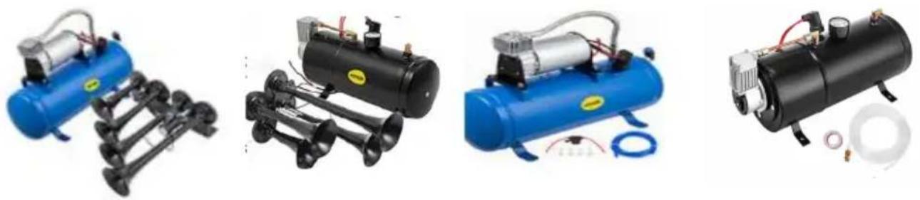
HS-660 HS-550 HS-661 HS-551
NEED HELP? CONTACT US!
Have product questions? Need technical support? Please feel free to contact us:
Technical Support and E-Warranty Certificate www.vevor.com/support
This is the original instruction, please read all manual instructions carefully before operating. VEVOR reserves a clear interpretation of user manual. The appearance of the product shall be subject to product you received. Please forgive us that we won't inform your data to where there are any technology or software updates on our product.
PARAMETER LIST
| 1 | air receiver | 9 | Piston connecting rod | 17 | High pressure copper tube | 25 | Horn tracheal joint |
| 2 | Carbon brush plate | 10 | cylinder | 18 | check valve | 26 | solenoid valve |
| 3 | Rotor gasket | 11 | radiator | 19 | Automatic pressure switch | 27 | Horn bracket and screws |
| 4 | rotor | 12 | Cylinder sealing ring | 20 | pressure gauge | 28 | hose |
| 5 | Rotor gasket | 13 | Air sheet | 21 | hose connector | 29 | drain valve |
| 6 | Motor buffer gasket | 14 | Gas seal ring | 22 | Motor power cord | ||
| 7 | motor housing | 15 | The cylinder cover | 23 | Pressure switch dust cover | ||
| 8 | Motor cover plate | 16 | Cylinder head fixing screw | 24 | horn |
CORRECT DISPOSAL
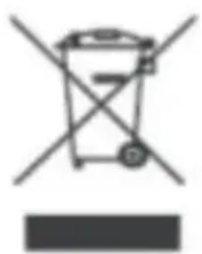
HS-660

HS-550

HS-661

HS-551
We continue to be committed to provide you with tools at competitive prices. "Save Half", "Half Price", or any other similar expressions used by us are only an estimate of the savings you might benefit from when buying certain tools from us among the major top brands, and do not necessarily mean to cover all categories offered by us. You are kindly reminded to verify carefully when you place an order with us if you are actually saving half in comparison with the top major brands.
MODEL: HS-660/HS-550/HS-661/HS-551
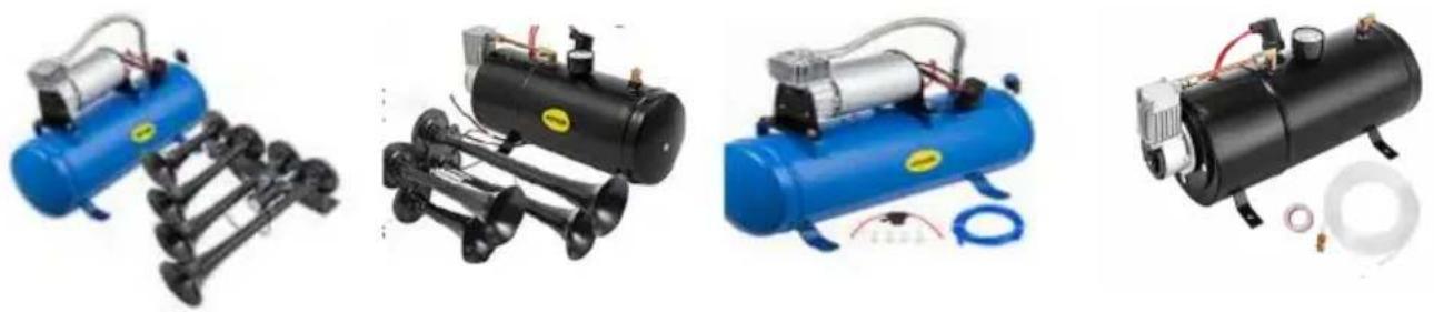
HS-660 HS-550 HS-661 HS-551
NEED HELP? CONTACT US!
Have product questions? Need technical support? Please feel free to contact us:
Technical Support and E-Warranty Certificate www.vevor.com/support
This is the original instruction. Please read all manual instructions carefully before operating. VEVOR reserves a clear interpretation of the user manual. The appearance of the product shall be subject to the product you received. Please forgive us that we won't inform you of any technology or software updates on our product.
PARAMETER LIST
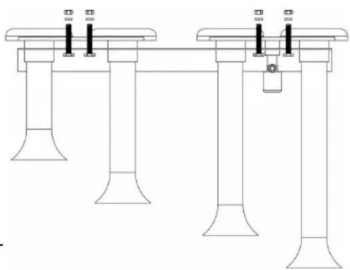
Mounting of Horns Model
Iron (negative
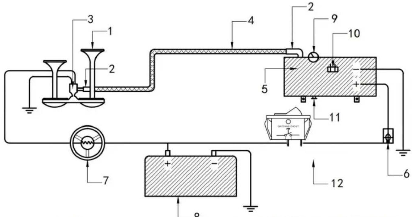
1 AIR HORN
2 GAS PIPE JOINT
3 AIR HORN SOLENOID
4 AIR TUBE
5 AIR COMPRESSOR
6 FUSE WIRE
7 HORN BUTTON
8 BATTERY IN THE VEHICLE
9 PRESSURE METER
10 PRESSURE SWITCH
11 DRAIN VALVE
12 POWER SWITCH
| 1 | air receiver | 9 | Piston connecting rod | 17 | High pressure copper tube | 25 | Horn tracheal joint |
| 2 | Carbon brush plate | 10 | cylinder | 18 | check valve | 26 | solenoid valve |
| 3 | Rotor gasket | 11 | radiator | 19 | Automatic pressure switch | 27 | Horn bracket and screws |
| 4 | rotor | 12 | Cylinder sealing ring | 20 | pressure gauge | 28 | hose |
| 5 | Rotor gasket | 13 | Air sheet | 21 | hose connector | 29 | drain valve |
| 6 | Motor buffer gasket | 14 | Gas seal ring | 22 | Motor power cord | ||
| 7 | motor housing | 15 | The cylinder cover | 23 | Pressure switch dust cover | ||
| 8 | Motor cover plate | 16 | Cylinder head fixing screw | 24 | horn |
CORRECT DISPOSAL
HS-660

HS-550

HS-661

HS-551
We continue to be committed to provide you tools with competitive prices. "Save Half", "Half Price" or any other similar expressions used by us only an estimate of savings you might benefit from buying certain tools with us of the major top brands and does not necessarily mean to cover all categories offered by us. You are kindly reminded to verify carefully when you are placed with us if you are actually saving half in comparison with the top major brands.
MODEL: HS-660/HS-550/HS-661/ HS-551
HS-660 HS-550 HS-661 HS-551
NEED HELP? CONTACT US!
Have product questions? Need technical support? Please feel free to contact us:
Technical Support and E-Warranty Certificate www.vevor.com/support
This is the original instruction. Please read all manual instructions carefully before operating. VEVOR reserves a clear interpretation of the user manual. The appearance of the product shall be subject to the product you received. Please forgive us that we won't inform you of any technology or software updates on our product.
PARAMETER LIST
| 1 | air receiver | 9 | Piston connecting rod | 17 | High pressure copper tube | 25 | Horn tracheal joint |
| 2 | Carbon brush plate | 10 | cylinder | 18 | check valve | 26 | solenoid valve |
| 3 | Rotor gasket | 11 | radiator | 19 | Automatic pressure switch | 27 | Horn bracket and screws |
| 4 | rotor | 12 | Cylinder sealing ring | 20 | pressure gauge | 28 | hose |
| 5 | Rotor gasket | 13 | Air sheet | 21 | hose connector | 29 | drain valve |
| 6 | Motor buffer gasket | 14 | Gas seal ring | 22 | Motor power cord | ||
| 7 | motor housing | 15 | The cylinder cover | 23 | Pressure switch dust cover | ||
| 8 | Motor cover plate | 16 | Cylinder head fixing screw | 24 | horn |
HS-660

HS-550

HS-661

HS-551
We continue to be committed to providing you with tools at competitive prices. "Save Half", "Half Price" or any other similar expressions used by us are only an estimate of savings you might benefit from buying certain tools with us compared to the major top brands, and does not necessarily mean to cover all categories offered by us. You are kindly reminded to verify carefully when you are placed with us if you are actually saving half in comparison with the top major brands.
MODEL: HS-660/HS-550/HS-661/HS-551
HS-660 HS-550 HS-661 HS-551
NEED HELP? CONTACT US!
Have product questions? Need technical support? Please feel free to contact us:
Technical Support and E-Warranty Certificate www.vevor.com/support
This is the original instruction. Please read all manual instructions carefully before operating. VEVOR reserves a clear interpretation of the user manual. The appearance of the product shall be subject to the product you received. Please forgive us that we won't inform you if there are any technology or software updates on our product.
PARAMETER LIST
| 1 | air receiver | 9 | Piston connecting rod | 17 | High pressure copper tube | 25 | Horn tracheal joint |
| 2 | Carbon brush plate | 10 | cylinder | 18 | check valve | 26 | solenoid valve |
| 3 | Rotor gasket | 11 | radiator | 19 | Automatic pressure switch | 27 | Horn bracket and screws |
| 4 | rotor | 12 | Cylinder sealing ring | 20 | pressure gauge | 28 | hose |
| 5 | Rotor gasket | 13 | Air sheet | 21 | hose connector | 29 | drain valve |
| 6 | Motor buffer gasket | 14 | Gas seal ring | 22 | Motor power cord | ||
| 7 | motor housing | 15 | The cylinder cover | 23 | Pressure switch dust cover | ||
| 8 | Motor cover plate | 16 | Cylinder head fixing screw | 24 | horn |
HS-660

HS-550

HS-661

HS-551
We continue to be committed to provide you with tools at competitive prices. "Save Half", "Half Price" or any other similar expressions used by us are only an estimate of savings you might benefit from buying certain tools with us compared to the major top brands, and does not necessarily mean to cover all categories offered by us. You are kindly reminded to verify carefully when you are placed with us if you are actually saving half in comparison with the top major brands.
MODEL: HS-660/HS-550/HS-661/ HS-551
HS-660 HS-550 HS-661 HS-551
NEED HELP? CONTACT US!
Have product questions? Need technical support? Please feel free to contact us:
Technical Support and E-Warranty Certificate www.vevor.com/support
This is the original instruction. Please read all manual instructions carefully before operating. VEVOR reserves a clear interpretation of the user manual. The appearance of the product shall be subject to the product you received. Please forgive us that we won't inform you if there are any technology or software updates on our product.
PARAMETER LIST
1 AIR HORN
2 GAS PIPE JOINT
3 AIR HORN SOLENOID
4 AIR TUBE
5 AIR COMPRESSOR
6 FUSE WIRE
7 HORN BUTTON
8 BATTERY IN THE VEHICLE
9 PRESSURE METER
10 PRESSURE SWITCH
11 DRAIN VALVE
12 POWER SWITCH
| 1 | air receiver | 9 | Piston connecting rod | 17 | High pressure copper tube | 25 | Horn tracheal joint |
| 2 | Carbon brush plate | 10 | cylinder | 18 | check valve | 26 | solenoid valve |
| 3 | Rotor gasket | 11 | radiator | 19 | Automatic pressure switch | 27 | Horn bracket and screws |
| 4 | rotor | 12 | Cylinder sealing ring | 20 | pressure gauge | 28 | hose |
| 5 | Rotor gasket | 13 | Air sheet | 21 | hose connector | 29 | drain valve |
| 6 | Motor buffer gasket | 14 | Gas seal ring | 22 | Motor power cord | ||
| 7 | motor housing | 15 | The cylinder cover | 23 | Pressure switch dust cover | ||
| 8 | Motor cover plate | 16 | Cylinder head fixing screw | 24 | horn |
PROPER DISPOSAL
HS-660

HS-550

HS-661

HS-551
We continue to be committed to provide you with tools at competitive prices. "Save Half", "Half Price", or any other similar expressions used by us are only an estimate of the savings you might benefit from buying certain tools from us compared to the major top brands, and do not necessarily mean to cover all categories offered by us. You are kindly reminded to verify carefully when you place an order with us if you are actually saving half in comparison with the top major brands.
MODEL: HS-660/HS-550/HS-661/HS-551
HS-660 HS-550 HS-661 HS-551
NEED HELP? CONTACT US!
Have product questions? Need technical support? Please feel free to contact us:
Technical Support and E-Warranty Certificate www.vevor.com/support
This is the original instruction. Please read all manual instructions carefully before operating. VEVOR reserves a clear interpretation of the user manual. The appearance of the product shall be subject to the product you received. Please forgive us that we won't inform you in advance if there are any technology or software updates on our product.
PARAMETER LIST
| Model | HS-660 | HS-550 | HS-661 | HS-551 |
| Spanning | 12 | 12 | 12 | 12 |
| Vermogen (w) | 190 | 170 | 190 | 170 |
| Werkdrukbereik (psi) | AAN: 90UIT: 120 | AAN: 90UIT: 120 | AAN: 90UIT: 120 | AAN : 90UIT : 120 |
| Capaciteit opslagtank (gal) | 1.6 | 0,8 | 1.6 | 0,8 |
| Maximale geluidsuitvoer (dB) | 1 5 0 | 150 | 150 | 150 |
| Nettogewicht (kg) | 6.1 | 5.45 | 4,65 | 4.5 |
PART LIST
| NEE . | Naam | HS-660 | HS-550 | HS-661 | HS-551 |
| 1 | compressor | 1 | 1 | 1 | 1 |
| 2 | hoorn | 2 | 1 | 0 | 0 |
| 3 | Luchtbuis | 1 | 1 | 1 | 1 |
| 4 | Hoornverbinding | 1 | 0 | 0 | 0 |
| 5 | Hoornmontage | 1 | 1 | 0 | 0 |
| 6 | Teflontape | 1 | 1 | 1 | 1 |
| 7 | Rubberen pad | 4 | 4 | 4 | 4 |
| 8 | Veiligheidsmontagestoel | 1 | 1 | 1 | 1 |
| 9 | Samensmelten | 1 | 1 | 1 | 1 |
| 10 | M6 bout | 12 | 8 | 4 | 4 |
| 11 | M6 moer | 12 | 8 | 4 | 4 |
| 12 | M 6 ring | 12 | 4 | 4 | 4 |
| 13 | Luchtpijpverbinding | 0 | 0 | 1 | 1 |
SECURITY & WARNINGS
| 1 | air receiver | 9 | Piston connecting rod | 17 | High pressure copper tube | 25 | Horn tracheal joint |
| 2 | Carbon brush plate | 10 | cylinder | 18 | check valve | 26 | solenoid valve |
| 3 | Rotor gasket | 11 | radiator | 19 | Automatic pressure switch | 27 | Horn bracket and screws |
| 4 | rotor | 12 | Cylinder sealing ring | 20 | pressure gauge | 28 | hose |
| 5 | Rotor gasket | 13 | Air sheet | 21 | hose connector | 29 | drain valve |
| 6 | Motor buffer gasket | 14 | Gas seal ring | 22 | Motor power cord | ||
| 7 | motor housing | 15 | The cylinder cover | 23 | Pressure switch dust cover | ||
| 8 | Motor cover plate | 16 | Cylinder head fixing screw | 24 | horn |
CORRECT DISPOSAL

HS-660

HS-550

HS-661

HS-551
We continue to be committed to provide you tools with competitive price. "Save Half", "Half Price" or any other similar expressions used by us only an estimate of savings you might benefit from buying certain tools with us of the major top brands and does not necessarily mean to cover all categories offered by us. You are kindly reminded to verify carefully when you are placed with us if you are actually saving half in comparison with the top major
MODEL: HS-660/HS-550/HS-661/ HS-551
HS-660 HS-550 HS-661 HS-551
NEED HELP? CONTACT US!
Have product questions? Need technical support? Please feel free to contact us:
Technical Support and E-Warranty Certificate www.vevor.com/support
This is the original instruction, please read all manual instructions carefully before operating. VEVOR reserves a clear interpretation of user manual. The appearance of the product shall be subject to product you received. Please forgive us that we won't inform your data on our product.
PARAMETER LIST
| Modell | HS-660 | HS-550 | HS-661 | HS-551 |
| Spänning | 12 | 12 | 12 | 12 |
| Effekt (w) | 190 | 170 | 190 | 170 |
| Arbetstryckområde (psi) | PÅ: 90 AV: 120 | PÅ: 90 AV: 120 | PÅ: 90 AV: 120 | PÅ : 90 AV : 120 |
| Lagringstankens kapacitet (gallon) | 1.6 | 0,8 | 1.6 | 0,8 |
| Maximalt ljudutgångsvärde (dB) | 1 5 0 | 150 | 150 | 150 |
| Nettovikt (kg) | 6.1 | 5,45 | 4,65 | 4,5 |
PART LIST
| NO. | Namn | HS-660 | HS-550 | HS-661 | HS-551 |
| 1 | kompressor | 1 | 1 | 1 | 1 |
| 2 | horn | 2 | 1 | 0 | 0 |
| 3 | Luftslang | 1 | 1 | 1 | 1 |
| 4 | Hornanslutning | 1 | 0 | 0 | 0 |
| 5 | Hornfäste | 1 | 1 | 0 | 0 |
| 6 | Teflontejp | 1 | 1 | 1 | 1 |
| 7 | Gummidyna | 4 | 4 | 4 | 4 |
| 8 | Säkerhetsmonteringssäte | 1 | 1 | 1 | 1 |
| 9 | Säkring | 1 | 1 | 1 | 1 |
| 10 | M 6 bult | 12 | 8 | 4 | 4 |
| 11 | M 6 mutter | 12 | 8 | 4 | 4 |
| 12 | M 6 bricka | 12 | 4 | 4 | 4 |
| 13 | Luftrörskoppling | 0 | 0 | 1 | 1 |
SECURITY & WARNINGS
1 AIR HORN 2 GAS PIPE JOINT 3 AIR HORN SOLENOID 4 AIR TUBE 5 AIR COMPRESSOR 6 FUSE WIRE 7 HORN BUTTON
8 BATTERY IN THE VEHICLE 9 PRESSURE METER 10 PRESSURE SWITCH 11 DRAIN VALVE 12 POWER SWITCH
| 1 | air receiver | 9 | Piston connecting rod | 17 | High pressure copper tube | 25 | Horn tracheal joint |
| 2 | Carbon brush plate | 10 | cylinder | 18 | check valve | 26 | solenoid valve |
| 3 | Rotor gasket | 11 | radiator | 19 | Automatic pressure switch | 27 | Horn bracket and screws |
| 4 | rotor | 12 | Cylinder sealing ring | 20 | pressure gauge | 28 | hose |
| 5 | Rotor gasket | 13 | Air sheet | 21 | hose connector | 29 | drain valve |
| 6 | Motor buffer gasket | 14 | Gas seal ring | 22 | Motor power cord | ||
| 7 | motor housing | 15 | The cylinder cover | 23 | Pressure switch dust cover | ||
| 8 | Motor cover plate | 16 | Cylinder head fixing screw | 24 | horn |

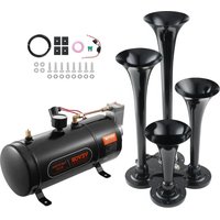
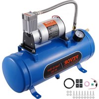
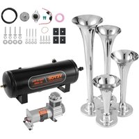
Brand : Vevor
Model : HS-551
Category : Air horn